WO2014017143A1 - モータ駆動制御装置 - Google Patents
モータ駆動制御装置 Download PDFInfo
- Publication number
- WO2014017143A1 WO2014017143A1 PCT/JP2013/063133 JP2013063133W WO2014017143A1 WO 2014017143 A1 WO2014017143 A1 WO 2014017143A1 JP 2013063133 W JP2013063133 W JP 2013063133W WO 2014017143 A1 WO2014017143 A1 WO 2014017143A1
- Authority
- WO
- WIPO (PCT)
- Prior art keywords
- motor
- fan motor
- drive
- voltage
- rotational speed
- Prior art date
- Legal status (The legal status is an assumption and is not a legal conclusion. Google has not performed a legal analysis and makes no representation as to the accuracy of the status listed.)
- Ceased
Links
Images






Classifications
-
- H—ELECTRICITY
- H02—GENERATION; CONVERSION OR DISTRIBUTION OF ELECTRIC POWER
- H02P—CONTROL OR REGULATION OF ELECTRIC MOTORS, ELECTRIC GENERATORS OR DYNAMO-ELECTRIC CONVERTERS; CONTROLLING TRANSFORMERS, REACTORS OR CHOKE COILS
- H02P6/00—Arrangements for controlling synchronous motors or other dynamo-electric motors using electronic commutation dependent on the rotor position; Electronic commutators therefor
- H02P6/20—Arrangements for starting
-
- H—ELECTRICITY
- H02—GENERATION; CONVERSION OR DISTRIBUTION OF ELECTRIC POWER
- H02P—CONTROL OR REGULATION OF ELECTRIC MOTORS, ELECTRIC GENERATORS OR DYNAMO-ELECTRIC CONVERTERS; CONTROLLING TRANSFORMERS, REACTORS OR CHOKE COILS
- H02P6/00—Arrangements for controlling synchronous motors or other dynamo-electric motors using electronic commutation dependent on the rotor position; Electronic commutators therefor
- H02P6/14—Electronic commutators
- H02P6/16—Circuit arrangements for detecting position
- H02P6/18—Circuit arrangements for detecting position without separate position detecting elements
-
- H—ELECTRICITY
- H02—GENERATION; CONVERSION OR DISTRIBUTION OF ELECTRIC POWER
- H02P—CONTROL OR REGULATION OF ELECTRIC MOTORS, ELECTRIC GENERATORS OR DYNAMO-ELECTRIC CONVERTERS; CONTROLLING TRANSFORMERS, REACTORS OR CHOKE COILS
- H02P1/00—Arrangements for starting electric motors or dynamo-electric converters
- H02P1/16—Arrangements for starting electric motors or dynamo-electric converters for starting dynamo-electric motors or dynamo-electric converters
- H02P1/46—Arrangements for starting electric motors or dynamo-electric converters for starting dynamo-electric motors or dynamo-electric converters for starting an individual synchronous motor
-
- H—ELECTRICITY
- H02—GENERATION; CONVERSION OR DISTRIBUTION OF ELECTRIC POWER
- H02P—CONTROL OR REGULATION OF ELECTRIC MOTORS, ELECTRIC GENERATORS OR DYNAMO-ELECTRIC CONVERTERS; CONTROLLING TRANSFORMERS, REACTORS OR CHOKE COILS
- H02P6/00—Arrangements for controlling synchronous motors or other dynamo-electric motors using electronic commutation dependent on the rotor position; Electronic commutators therefor
- H02P6/14—Electronic commutators
- H02P6/16—Circuit arrangements for detecting position
- H02P6/17—Circuit arrangements for detecting position and for generating speed information
-
- H—ELECTRICITY
- H02—GENERATION; CONVERSION OR DISTRIBUTION OF ELECTRIC POWER
- H02P—CONTROL OR REGULATION OF ELECTRIC MOTORS, ELECTRIC GENERATORS OR DYNAMO-ELECTRIC CONVERTERS; CONTROLLING TRANSFORMERS, REACTORS OR CHOKE COILS
- H02P6/00—Arrangements for controlling synchronous motors or other dynamo-electric motors using electronic commutation dependent on the rotor position; Electronic commutators therefor
- H02P6/14—Electronic commutators
- H02P6/16—Circuit arrangements for detecting position
- H02P6/18—Circuit arrangements for detecting position without separate position detecting elements
- H02P6/181—Circuit arrangements for detecting position without separate position detecting elements using different methods depending on the speed
Definitions
- the present invention relates to a motor drive control device, and more particularly to a motor drive control device that drives a motor having a rotor and a stator by a rotor position sensorless control system.
- a motor In an air conditioner equipped with devices such as an outdoor fan and a compressor, a motor is often used as a power source of these devices, and the motor is driven and controlled by a motor drive control device.
- a motor drive control device that drives a motor by a rotor position sensorless control method is often used.
- the position of the rotor cannot be detected in the non-control state immediately before the motor is started.
- the motor when a motor is used as a drive source for an outdoor fan, the motor also rotates when an external force is applied to the outdoor fan due to wind or the like, even though the motor is not yet driven.
- Patent Document 1 Japanese Patent Laid-Open No. 2005-137106
- the phase of the rotor is detected from the induced voltage generated in the motor when the output of the drive voltage from the inverter to the motor is stopped.
- Technology is known.
- the motor is started according to the detected phase of the rotor.
- Patent Document 1 it is required to accurately detect the phase of the rotor.
- a circuit constituting the motor drive control device Adjustment is required. Therefore, the adjustment of the motor drive control device becomes complicated.
- Patent Document 1 requires a circuit for detecting the phase of the rotor, the cost is increased accordingly.
- the motor drive control device is a device that drives a motor having a rotor and a stator by a rotor position sensorless control system.
- the motor drive control device includes a rotation speed deriving unit, an activation unit, and a changing unit.
- the rotational speed deriving unit derives the rotational speed of the motor at least in a state immediately before starting the motor.
- the start unit outputs a drive signal based on at least one of a direct current excitation method and a forced drive method to the motor to start the motor.
- the direct current excitation method is a method in which the rotor position is fixed at a predetermined position by applying direct current to the motor.
- the forced drive method is a method of accelerating the motor to a predetermined number of revolutions by performing forced energization that applies a predetermined voltage and frequency to the motor.
- the changing unit changes a drive signal based on at least one of the direct current excitation method and the forced drive method according to the rotation number of the motor derived by the rotation number deriving unit.
- the drive signal based on the DC excitation method and / or the forced drive method is changed at least according to the number of rotations of the motor in the state immediately before starting the motor. That is, the drive signal based on the direct current excitation method and / or the forced drive method, which is output to the motor to start the motor, changes according to the rotational speed of the motor.
- the motor is activated by a drive signal corresponding to the motor rotation speed at least in the state immediately before the motor activation, so that the occurrence of an overcurrent and overvoltage state can be suppressed, and the activation of the motor can be easily performed without incurring costs. Stability can be secured.
- the change unit is The voltage or current of the drive signal is changed according to the number of rotations of the motor.
- the change unit is The frequency, voltage, or current value of the drive signal is changed according to the rotation speed of the motor.
- the motor drive control device is the motor drive control device according to any one of the first to third aspects.
- the changing unit is from the start of the motor to the normal rotation state.
- the voltage or current of the drive signal is continuously changed according to the number of rotations of the motor.
- a drive signal that changes momentarily according to the number of rotations of the motor is output to the motor from when the motor starts to the normal rotation state. Therefore, the occurrence of overcurrent and overvoltage can be suppressed more reliably.
- the motor drive control device is the motor drive control device according to any one of the first to fourth aspects, wherein the changing unit is responsive to an elapsed time since the start of the motor.
- the voltage or current of the drive signal is continuously changed.
- a drive signal corresponding to the elapsed time since the start of the motor is output to the motor. Therefore, the occurrence of overcurrent and overvoltage can be suppressed more reliably.
- a motor drive control device is the motor drive control device according to any one of the first to fifth aspects, wherein the changing unit is configured such that the rotational speed of the motor immediately before starting is greater than a predetermined rotational speed.
- the voltage or current of the drive signal output to the motor in order to start the motor is made smaller than the predetermined drive voltage or predetermined drive current output to the motor when the motor starts to start without rotating.
- the motor has already been rotated immediately before starting under the influence of an external force such as wind, and the rotational speed of the motor has become a predetermined rotational speed or more.
- this motor drive control device for example, when the rotational speed of the motor immediately before starting is larger than a predetermined rotational speed, for example, the duty or amplitude of the driving voltage output to the motor to start the motor, The duty or amplitude of the predetermined drive voltage is made smaller.
- the motor drive control device starts a motor that has already been rotated at a certain number of revolutions immediately before startup, the amount of current applied to the motor and the voltage applied to the startup unit become excessive. Phenomenon, and start-up stability of the motor can be secured.
- the motor drive control device is the motor drive control device according to any one of the first to sixth aspects, wherein the changing unit is from the start of the motor to the normal rotation state. In the meantime, the voltage or current of the drive signal is increased as the number of rotations of the motor increases.
- this motor drive control device increases, for example, the duty and amplitude of the drive voltage as the motor speed increases from when the motor starts to the normal rotation state. .
- the phenomenon that the amount of current supplied to the motor and the voltage applied to the starting unit become excessive and the step-out of the motor can be suppressed, and the starting stability of the motor can be ensured.
- the motor drive control device is the motor drive control device according to either the fourth aspect or the seventh aspect, wherein the changing unit starts from the start of the motor until the normal rotation state is reached. During this period, the voltage or current of the drive signal is increased with the elapsed time after the start of startup.
- This motor drive control device increases the duty, amplitude, etc. of the drive voltage, for example, with the elapsed time after the start of the start until the motor reaches the normal rotation state after the start of the start. As a result, the phenomenon that the amount of current supplied to the motor and the voltage applied to the starting unit become excessive and the step-out of the motor can be suppressed, and the starting stability of the motor can be ensured.
- the motor drive control device With the motor drive control device according to the first aspect of the present invention, it is possible to suppress the occurrence of overcurrent and overvoltage conditions, and it is possible to easily ensure the start-up stability of the motor without incurring costs.
- the motor According to the motor drive control device of the second aspect of the present invention, the motor can be reliably started even if the DC excitation method is employed.
- the motor According to the motor drive control device of the third aspect of the present invention, the motor can be reliably started even if the forced drive method is employed.
- the motor drive control device According to the motor drive control device according to the fourth and fifth aspects of the present invention, the occurrence of overcurrent and overvoltage can be more reliably suppressed.
- the motor drive control device of the sixth aspect of the present invention it is possible to suppress the phenomenon that the amount of current supplied to the motor and the voltage applied to the starting unit become excessive, and ensure the starting stability of the motor. can do.
- the motor drive control device According to the motor drive control device according to the seventh aspect and the eighth aspect of the present invention, it is possible to suppress the phenomenon that the amount of current applied to the motor and the voltage applied to the starting unit become excessive and the motor step-out. Thus, the starting stability of the motor can be ensured.
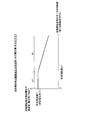
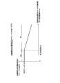
- 6 is a graph conceptually illustrating, as an example, a change with time in a frequency of a drive voltage (or a voltage value of the drive voltage) from when the fan motor starts to start normal rotation.
- the graph which shows notionally the relationship between the rotation speed of the fan motor just before start-up, and the duty of the drive voltage at the time of start-up. 6 is a graph conceptually illustrating, as an example, a change with time in duty of a drive voltage from when a fan motor starts to start to the end of DC excitation.
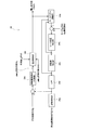
- FIG. 1 is a configuration diagram of an entire motor drive control system 100 including a brushless DC motor 51 and a motor drive control device 20 according to the present embodiment for driving the brushless DC motor 51.
- the brushless DC motor 51 is a fan motor used as a drive source of an outdoor fan 15 which is one of the devices included in the outdoor unit 10 (see FIG. 2) of the heat pump apparatus, and is driven by application of an AC voltage. It is.
- the motor drive control device 20 is mounted in the outdoor unit 10.
- the outdoor unit 10 mainly includes various devices such as a compressor 11, a water heat exchanger 12, an expansion valve 13, an evaporator 14, and an outdoor fan 15.
- the compressor 11, the water heat exchanger 12, the expansion valve 13 and the evaporator 14 are sequentially connected to constitute a refrigeration cycle.
- the compressor 11 compresses the refrigerant circulating in the refrigeration cycle.
- the water heat exchanger 12 is provided with a heat exchange water channel 16 through which water sent from a hot water storage tank unit (not shown) connected to the outdoor unit 10 passes, and water flowing through the heat exchange water channel 16 and Heat exchange can be performed with the refrigerant.
- the expansion valve 13 is an electrically controlled valve that depressurizes the refrigerant circulating in the refrigeration cycle.
- the evaporator 14 is for causing heat exchange between the refrigerant in the refrigerant cycle and the air to evaporate the refrigerant.
- the outdoor fan 15 is a propeller fan, for example, and guides air from the outside of the outdoor unit 10 to the evaporator 14 by rotation.
- the brushless DC motor 51 is a three-phase motor, and includes a stator 52 and a rotor 53.
- the stator 52 includes U-phase, V-phase, and W-phase drive coils Lu, Lv, and Lw that are star-connected. One ends of the drive coils Lu, Lv, and Lw are connected to drive coil terminals TU, TV, and TW of U-phase, V-phase, and W-phase wirings extending from the inverter 25, respectively.
- the other ends of the drive coils Lu, Lv, and Lw are connected to each other as a terminal TN. These three-phase drive coils Lu, Lv, and Lw generate an induced voltage according to the rotational speed and the position of the rotor 53 as the rotor 53 rotates.
- the rotor 53 includes a plurality of permanent magnets including N poles and S poles, and rotates about the rotation axis with respect to the stator 52.
- the rotation of the rotor 53 is output to the outdoor fan 15 via an output shaft (not shown) that is on the same axis as the rotation shaft.
- the brushless DC motor 51 is referred to as a fan motor 51.
- the motor drive control device 20 includes a rectifying unit 21, a smoothing capacitor 22, a voltage detecting unit 23, a current detecting unit 24, an inverter (corresponding to a starting unit) 25, , A gate drive circuit 26, a pre-startup rotational speed detection circuit (corresponding to a rotational speed deriving section together with a rotational speed estimation section 28c of a sensorless control circuit 28 described later) 27, and a sensorless control circuit 28 (mainly corresponding to a changing section); And a microcomputer 29.
- the gate drive circuit 26, the pre-startup rotation speed detection circuit 27, and the sensorless control circuit 28 may be packaged in one integrated circuit package (specifically, an IC or an HIC).
- Rectifier The rectifier 21 is configured in a bridge shape by four diodes D1a, D1b, D2a, D2b. Specifically, the diodes D1a and D1b and D2a and D2b are respectively connected in series. The cathode terminals of the diodes D1a and D2a are both connected to the plus side terminal of the smoothing capacitor 22 and function as the positive side output terminal of the rectifying unit 21.
- the anode terminals of the diodes D1b and D2b are connected to the minus side terminal of the smoothing capacitor 22 and function as the negative side output terminal of the rectifying unit 21.
- a connection point between the diodes D1a and D1b and a connection point between the diodes D2a and D2b are connected to the commercial power supply 91, respectively. That is, the connection point between the diodes D1a and D1b and the connection point between the diodes D2a and D2b each serve as an input to the rectifying unit 21.
- the rectifying unit 21 having such a configuration generates a DC power by rectifying the AC voltage output from the commercial power supply 91 and supplies the DC power to the smoothing capacitor 22.
- the smoothing capacitor 22 has one end connected to the positive output terminal of the rectifying unit 21 and the other end connected to the negative output terminal of the rectifying unit 21.
- the smoothing capacitor 22 smoothes the DC power supplied from the rectifying unit 21, that is, the voltage rectified by the rectifying unit 21.
- the voltage after smoothing by the smoothing capacitor 22 is referred to as “smoothed voltage Vfl”.
- the smoothed voltage Vfl is a voltage with a ripple lower than that of the voltage related to the DC power supply, and is applied to the inverter 25 connected to the subsequent stage of the smoothing capacitor 22, that is, the output side.
- condenser although an electrolytic capacitor, a ceramic capacitor, a tantalum capacitor, etc. are mentioned, in this embodiment, the case where an electrolytic capacitor is employ
- the voltage detection unit 23 is connected to the output side of the smoothing capacitor 22 and detects the voltage across the smoothing capacitor 22, that is, the value of the smoothed voltage Vfl. In particular, the voltage detection unit 23 performs a voltage detection operation after the fan motor 51 is started. Although not shown, such a voltage detector 23 is configured by, for example, connecting two resistors connected in series to each other in parallel to the smoothing capacitor 22 and dividing the smoothed voltage Vfl. The voltage value at the connection point between the two resistors is input to the sensorless control circuit 28. (2-4) Current Detection Unit The current detection unit 24 is connected between the smoothing capacitor 22 and the inverter 25 and connected to the negative output terminal side of the smoothing capacitor 22. The current detection unit 24 detects the motor current Im flowing through the fan motor 51 after the fan motor 51 is started.
- the current detection unit 24 is configured by an amplifier circuit using, for example, a shunt resistor and an operational amplifier that amplifies the voltage across the resistor.
- the motor current Im detected by the current detection unit 24 is input to the sensorless control circuit 28.
- (2-5) Inverter The inverter 25 is connected to the output side of the smoothing capacitor 22.
- the inverter 25 includes a plurality of insulated gate bipolar transistors (hereinafter simply referred to as transistors) Q3a, Q3b, Q4a, Q4b, Q5a, Q5b and a plurality of freewheeling diodes D3a, D3b, D4a, D4b, D5a and D5b are included.
- Transistors Q3a and Q3b, Q4a and Q4b, and Q5a and Q5b are connected in series with each other.
- the diodes D3a to D5b are connected in parallel to the transistors Q3a to Q5b by connecting the collector terminal of the transistor and the cathode terminal of the diode and connecting the emitter terminal of the transistor and the anode terminal of the diode. ing.
- the smoothed voltage Vf1 from the smoothing capacitor 22 is applied to the inverter 25. Then, the inverter 25 generates drive voltages SU1, SV1, and SW1 having a desired duty by turning on and off the transistors Q3a to Q5b at a timing instructed by the gate drive circuit 26.
- the drive voltages SU1, SV1, and SW1 are AC voltages for driving the fan motor 51.
- the fan motor 51 is connected to the connection points NU, NV, and NW of the transistors Q3a and Q3b, Q4a and Q4b, and Q5a and Q5b. Is output. That is, the inverter 25 supplies power to the fan motor 51.
- the inverter 25 When the fan motor 51 is activated, the inverter 25 according to the present embodiment outputs the drive voltages SU1, SV1, SW1 based on the forced drive method to the fan motor 51, and activates the motor 51.
- the forced drive method is a method of accelerating the motor to a predetermined rotational speed by forcibly energizing the fan motor 51.
- the drive method shifts from the forced drive method to the position estimation drive, that is, the rotor position sensorless control.
- the drive voltages SU1, SV1, and SW1 having a predetermined voltage value and frequency are applied to the fan motor 51 regardless of the position of the rotor 53 of the fan motor 51, and the fan motor 51 is forced. Start to start. Therefore, in the forced drive method, unlike the direct current excitation method described in the second embodiment to be described later, the operation of temporarily fixing the position of the rotor 53 is not performed before the fan motor 51 starts to be driven.
- the driving voltages SU1, SV1, and SW1 that can be driven even in such a state are output from the inverter 25 to the fan motor 51. Thereby, the fan motor 51 is forcibly started.
- the inverter 25 starts the fan motor 51 by starting with the drive voltages SU1, SV1, and SW1 in the forcible drive system having a frequency or voltage value at least according to the rotation speed of the fan motor 51 immediately before starting. . Then, after starting the fan motor 51, the inverter 25 outputs to the fan motor 51 drive voltages SU 1, SV 1, SW 1 in a forced drive system having a frequency or voltage value corresponding to the rotational state of the fan motor 51 being started. To do. That is, when the fan motor 51 is activated by the conventional forced drive method, the inverter outputs a drive voltage that is not related to the rotation speed of the fan motor 51, that is, a drive voltage having a constant frequency or voltage value.
- the fan motor 51 has a frequency or voltage value corresponding to the actual rotational state
- the rotor 53 is Drive voltages SU1, SV1, and SW1 that can forcibly start the fan motor 51 at any position are output. That is, the drive voltage SU1, SV1, SW1 at the time of start-up according to the present embodiment is the frequency or voltage value of the drive voltage output to the motor 51 when the fan motor 51 is started by the conventional forced drive method. It can be said that the voltage changes in accordance with the rotation state of the fan motor 51.
- FIG. 3 is a graph showing, as a concept, the frequency and voltage value Vstart1 of the drive voltages SU1, SV1, SW1 at the start of startup with respect to the rotational speed of the fan motor 51 immediately before the start of startup.
- the horizontal axis indicates the rotation speed of the fan motor 51 immediately before the start of activation (that is, the rotation speed detected by the pre-startup rotation speed detection circuit 27 described later.
- First rotation speed signal FG The drive voltages SU1, SV1, and SW1 output to the fan motor 51 are represented as frequencies and voltage values Vstart1. As shown in the rotational speed section A1 in FIG.
- the frequencies (or voltage values) Vstart1 of the drive voltages SU1, SV1, SW1 are The predetermined frequency F1 (or the predetermined voltage value V1) is set.
- Vstart1 is set to a frequency (or voltage value) smaller than the predetermined frequency F1 (or predetermined voltage value V1).
- the predetermined frequency F1 and the predetermined voltage value V1 are respectively the frequency and voltage value of the driving voltage output to the motor 51 when the fan motor 51 starts to start without rotating.
- the frequency (or voltage value) for the predetermined rotation speed pr1 and the frequency (or voltage value) for the rotation speed greater than or equal to the rotation speed pr1 are determined based on the characteristics of the fan motor 51, the outdoor fan 15, and the evaporator 14, etc. An appropriate value is set in advance by calculation, simulation, experiment, or the like.
- a sensorless control circuit 28 described later described later.
- a voltage command value Vpwm is generated to reduce the frequency or voltage value Vstart1 of the drive voltages SU1, SV1, SW1 output to the motor 51.
- FIG. 4 conceptually shows changes over time in the frequency and voltage values of the drive voltages SU1, SV1, and SW1 output to the fan motor 51 from immediately after the start of the fan motor 51 to the normal rotation state. It is a graph. As described above, in a state where the rotational speed is low, since the rotational speed is not correctly estimated, the rotational state during activation is estimated over time. In FIG.
- the horizontal axis represents time
- the vertical axis represents the frequency and voltage value of the drive voltages SU1, SV1, and SW1.
- the inverter 25 has a frequency or voltage value as time elapses from the start of the start of the fan motor 51 to the normal rotation state (that is, the state where the position estimation operation is possible).
- Drive voltages SU1, SV1, and SW1 that increase the voltage are output to the fan motor 51.
- the inverter 25 is forcibly driven having a frequency / voltage value corresponding to the actual rotational speed of the fan motor 51 from just before the start of the fan motor 51 to the normal rotation state.
- the drive voltages SU1, SV1, SW1 in the system are output to the fan motor 51.
- the fan motor 51 that has already been rotated by the influence of an external force such as wind or the inertial force immediately after the rotation is stopped before the start-up is compared with the case where the overcurrent state or Overvoltage and step-out conditions are less likely to occur.
- the fan motor 51 is activated by the forced drive method, and the drive voltages SU1, SV1, and SW1 at that time have frequencies and voltages in consideration of the actual rotational speed of the fan motor 51. Therefore, each value of the motor current and voltage based on the drive voltages SU1, SV1, and SW1, which is further added to the voltage induced in the motor 51, is appropriate according to the current rotational speed of the fan motor 51. Value. Therefore, overcurrent, overvoltage, and motor step-out are less likely to occur.
- the gate drive circuit 26 changes the on / off states of the transistors Q3a to Q5b of the inverter 25 based on the voltage command value Vpwm from the sensorless control circuit 28.
- the gate drive circuit 26 is configured so that the drive voltages SU1, SV1, and SW1 having the duty determined by the sensorless control circuit 28 are output from the inverter 25 to the fan motor 51, so that the gates of the transistors Q3a to Q5b are output.
- the gate control voltages Gu, Gx, Gv, Gy, Gw, and Gz to be applied to are generated.
- the generated gate control voltages Gu, Gx, Gv, Gy, Gw, Gz are applied to the gate terminals of the respective transistors Q3a to Q5b.
- the voltage command value Vpwm is a command value for determining the duty of the drive voltages SU1, SV1, and SW1, which is one of the parameters related to the drive voltages SU, SV, and SW. That is, in this embodiment, the case where the fan motor 51 is PWM-controlled is taken as an example.
- the pre-startup speed detection circuit 27 has an input connected to the W-phase drive coil terminal TW of the fan motor 51 and an output connected to the sensorless control circuit 28. . In other words, it can be said that the pre-startup rotation speed detection circuit 27 is located on the rear side of the inverter 25.
- the pre-startup rotation speed detection circuit 27 is based on the W-phase induced voltage Vwn generated in the drive coil Lw mainly when the fan motor 51 is rotating before the start-up. Is detected.
- FIG. 5 shows a case where the pre-startup rotation speed detection circuit 27 includes a filter 27a, a comparator 27b, and a calculation unit 27c.
- the filter 27a is a low-pass filter, for example, and receives the induced voltage Vwn in the rotating fan motor 51, and removes noise components and harmonic components from the induced voltage Vwn.
- the comparator 27b receives the induced voltage Vwn after passing through the filter 27a and a reference voltage Vref having a predetermined voltage value.
- the comparator 27b outputs a pulse voltage based on the induced voltage Vwn based on the magnitude of these input voltages.
- the pulse voltage is input to the calculation unit 27c, and the frequency of the voltage is calculated to calculate the rotation speed of the fan motor 51.
- the first rotation speed signal FG1 indicating the rotation speed of the fan motor 51 before starting obtained in this way is a pulse signal having a period corresponding to the rotation speed of the motor 51, or the frequency of the signal is fixed.
- the pulse signal has a duty corresponding to the rotational speed of the motor 51.
- the rotation speed signal FG1 is input to the sensorless control circuit 28.
- the rotation speed detection circuit 27 before startup is configured to simply detect the rotation speed regardless of whether the rotation direction of the fan motor 51 before startup is the forward direction or the reverse direction.
- the sensorless control circuit 28 is connected to the voltage detection unit 23, the current detection unit 24, the gate drive circuit 26, the pre-startup rotation number detection circuit 27, and the microcomputer 29.
- the sensorless control circuit 28 is a circuit that drives the fan motor 51 by a rotor position sensorless system.
- the sensorless control circuit 28 estimates the position of the rotor 53 of the fan motor 51 after startup by the rotor position sensorless method, and estimates the rotational speed of the fan motor 51 based on the estimated position of the rotor 53. To do.
- a signal indicating the number of rotations of the fan motor 51 after startup is referred to as “second rotation number signal FG2”.
- the second rotation speed signal FG2 is input to the microcomputer 29. Further, when an operation command including the rotation speed command Vfg is sent from the microcomputer 29, the sensorless control circuit 28 receives this operation command, the estimated position of the rotor 53, the estimated rotation speed, and the detection result of the voltage detector 23.
- the rotor position sensorless system means various parameters indicating the characteristics of the fan motor 51, the smoothed voltage Vfl (that is, the detection result of the voltage detection unit 23), and the motor current Im (that is, the detection result of the current detection unit 24). , And a predetermined mathematical model related to the control of the fan motor 51, etc., to perform estimation of the position of the rotor 53, estimation of the rotational speed, PI control for the rotational speed, PI control for the motor current Im, and the like.
- various parameters indicating the characteristics of the fan motor 51 include the winding resistance, inductance component, induced voltage, and number of poles of the fan motor 51 used.
- FIG. 6 simply shows an example of the configuration of the sensorless control circuit 28 that performs the rotor position sensorless control in consideration of the mathematical model.
- the sensorless control circuit 28 in FIG. 6 mainly includes a motor model calculation unit 28a, a rotor position estimation unit 28b, a rotation number estimation unit 28c (corresponding to a rotation number deriving unit together with the rotation number detection circuit 27 before startup), an LPF 28d, and a rotation number control.
- the unit 28e and the current control unit 28f are included.
- the motor model calculation unit 28a uses various parameters indicating the characteristics of the fan motor 51 as a motor model, and calculates the ideal motor current Im from the voltage command value Vpwm to the motor 51, the estimated position of the rotor 53, and the estimated rotational speed.
- the rotor position estimator 28b estimates the position of the rotor 53 at the current time using the result obtained by subtracting the ideal value and the motor current Im actually detected by the current detector 24 as an input.
- the rotation speed estimation unit 28 c estimates the current rotation speed of the fan motor 51 using the estimated position of the rotor 53.
- the estimation results in the respective estimation units 28b and 28c are used for correction processing in which the difference between the ideal value of the motor current Im and the actual motor current Im becomes “0” and correction of the motor model in the motor model calculation unit 28a. Used.
- the LPF 28d removes a noise component and a harmonic component from the estimated rotational speed.
- the rotation speed of the fan motor 51 output from the LPF 28d becomes a desired second rotation speed signal FG2 by the waveform shaping section 28g and is output to the microcomputer 29.
- the second rotational speed signal FG2 is a pulse signal having a period corresponding to the rotational speed of the fan motor 51, or a duty corresponding to the rotational speed of the motor 51, although the frequency is fixed, like the first rotational speed signal FG1. It has a pulse signal.
- the rotation speed of the fan motor 51 output from the LPF 28d is subtracted from the rotation speed command Vfg included in the operation command sent from the microcomputer 29.
- the rotation speed control unit 28e performs PI control on the rotation speed.
- a voltage command value Vpwm including the duty of the drive voltages SU1, SV1, and SW1 is generated and input to the gate drive circuit 26.
- the voltage command value Vpwm is input to the motor model calculation unit 28a, and further correction of the motor model is performed.
- a dq coordinate system in which the direction of magnetic flux created by the permanent magnet of the rotor 53 is defined as the d-axis, and the direction advanced by ⁇ / 2 is defined as the q-axis.
- the “q-axis current command value Vq” is a command value of q-axis current that contributes to the torque of the fan motor 51, and the “d-axis current command value Vd” does not contribute to the torque of the fan motor 51.
- the sensorless control circuit 28 having such a configuration estimates the position of the rotor 53 and the rotational speed of the fan motor 51 when the inverter 25 is controlled by the microcomputer 29, the gate drive circuit 26, and the like. It can be said that the voltage command value Vpwm corresponding to these estimation results is output.
- the sensorless control circuit 28 having such a configuration is based on a forced drive system so that the output operation of the drive voltages SU1, SV1, SW1 described in “(2-5) Inverter” is realized. An operation is performed to change the frequency or voltage value of the drive voltages SU1, SV1, SW1 according to at least the rotation speed immediately before the start-up in the state immediately before the start-up of the fan motor 51.
- the sensorless control circuit 28 determines the drive voltages SU1, SV1, and SW1 based on the forced drive method in accordance with the elapsed time from when the fan motor 51 is activated until it reaches the normal rotation state. Change frequency or voltage continuously. For example, as shown in FIG. 4, the sensorless control circuit 28 increases with time from the start of the start of the fan motor 51 to the normal rotation state (that is, the state where the position estimation operation is enabled). The voltage command value Vpwm is continuously generated so that the frequency or voltage value of the drive voltages SU1, SV1, SW1 also increases.
- the microcomputer 29 is mainly connected to the sensorless control circuit 28 as shown in FIG. Although not shown, the microcomputer 29 is also connected to an outdoor unit side control unit that controls each device of the outdoor unit 10 in an integrated manner. For example, the microcomputer 29 monitors the rotational speed (that is, the second rotational speed signal FG2) of the fan motor 51 after starting the start-up, or performs sensorless control on the operation command including the rotational speed command start command and the rotational speed command Vfg. Or output to the circuit 28.
- the motor drive control device 20 of the present embodiment will be described with reference to FIG.
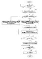
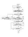
- FIG. 7 is a flowchart showing the operation performed by the motor drive control device 20.
- Steps S1 to S2 When the microcomputer 29 obtains an operation start instruction for the outdoor fan 15 from the outdoor unit side control unit of the outdoor unit 10 (Yes in S1), the pre-startup rotation speed detection circuit 27 is The number of rotations of the fan motor 51 is detected (S2). As a result, the sensorless control circuit 28 receives the first rotation speed signal FG1 indicating the rotation speed of the fan motor 51 before activation. Step S3: The sensorless control circuit 28 compares the rotational speed in step S2 with the predetermined rotational speed pr1.
- Step S4 In Step S3, when the rotational speed in Step S2 (that is, the rotational speed of the fan motor 51 before activation) is smaller than the predetermined rotational speed pr1 (No in S3), the rotational speed interval A1 in FIG. As shown, the sensorless control circuit 28 sets the frequency (or voltage value) Vstart1 of the drive voltages SU1, SV1, and SW1 for starting the fan motor 51 to the predetermined frequency F1 (or the predetermined voltage value V1).
- Step S5 In Step S3, when the rotational speed in Step S2 (that is, the rotational speed of the fan motor 51 before activation) is larger than the predetermined rotational speed pr1 (Yes in S3), the rotational speed interval B1 in FIG. As shown, the sensorless control circuit 28 sets the frequency (or voltage value) Vstart1 of the drive voltages SU1, SV1, and SW1 for starting the fan motor 51 to be smaller than the predetermined frequency F1 (or the predetermined voltage value V1). (Or voltage value).
- Step S6 The voltage command value Vpwm representing the frequency or voltage value Vstart1 set in steps S4 and S5 is input to the gate drive circuit 26, and the inverter 25 to the fan motor 51 is set in steps S4 and S5.
- Drive voltages SU1, SV1, and SW1 having different frequencies or voltage values are output.
- the drive voltages SU1, SV1, and SW1 are voltages for starting the fan motor 51 by the forced drive method, and thus the fan motor 51 starts to start.
- Step S7 As shown in FIG. 4, the sensorless control circuit 28 changes the frequency or voltage value of the drive voltages SU1, SV1, SW1 over time. Thus, drive voltage SU1, SV1, SW1 having a continuously changing frequency or voltage value is output from the inverter 25 to the fan motor 51.
- Steps S10 to S11 Until the microcomputer 29 obtains an instruction to stop driving the outdoor fan 15 (No in S10), the motor drive control device 20 continues the rotor position sensorless drive for the fan motor 51.
- the microcomputer 29 receives an instruction to stop driving the outdoor fan 15 (Yes in S10), the output of the drive voltages SU1, SV1, and SW1 to the fan motor 51 by the inverter 25 is stopped, and the fan motor 51 stops driving. (S11).
- the drive voltages SU1, SV1, and SW1 based on the forced drive method are changed at least immediately before the fan motor 51 is started.
- the drive voltages SU1, SV1, and SW1 based on the forced drive system that is output to the fan motor 51 to start the fan motor 51 change according to the rotation state of the fan motor 51.
- the fan motor 51 is started by the drive voltages SU1, SV1, and SW1 corresponding to the rotation state of the fan motor 51 at least in the state immediately before starting the motor, it is possible to suppress the occurrence of an overcurrent and an overvoltage state, thereby reducing the cost.
- the start-up stability of the fan motor 51 can be ensured without being applied.
- the fan motor 51 when the rotational speed of the fan motor 51 immediately before starting is equal to or higher than the predetermined rotational speed pr1, the fan motor 51 is started to start the fan motor 51.
- the frequency (or voltage value) Vstart1 of the drive voltages SU1, SV1, and SW1 to be output to is set smaller than the predetermined frequency F1 (or the predetermined voltage value V1).
- the frequency or voltage value of the drive voltages SU1, SV1, SW1 is increased with the increase in the rotation speed of the fan motor 51 from the start of the fan motor 51 to the normal rotation state. It will be set larger. Thereby, the phenomenon that the motor current Im flowing through the fan motor 51 and the voltage of the smoothing capacitor 22 become excessive and the step-out of the fan motor 51 can be suppressed, and the start-up stability of the fan motor 51 can be ensured. .
- the frequency or voltage value of the drive voltage is set to be larger with the elapsed time after the start of the start-up after the fan motor 51 starts to the normal rotation state.
- the phenomenon that the motor current Im flowing through the fan motor 51 and the voltage of the smoothing capacitor 22 become excessive and the step-out of the fan motor 51 can be suppressed, and the start-up stability of the fan motor 51 can be ensured.
- the fan motor 51 is activated by the so-called forced drive method has been described.
- a case will be described in which the fan motor 51 is activated using a DC excitation method at the start of activation in order to further ensure activation.
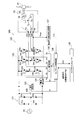
- FIG. 8 is a configuration diagram of the entire motor drive control system 200 including the motor drive control device 120 according to the present embodiment.
- the motor drive control apparatus 120 shown in FIG. 8 differs in part from the motor drive control apparatus 20 according to the first embodiment, the configuration is the same as the motor drive control apparatus 20 according to the first embodiment. It is. That is, the motor drive control device 120 includes a rectifying unit 121, a smoothing capacitor 122, a voltage detecting unit 123, a current detecting unit 124, an inverter (corresponding to a starting unit) 125, a gate driving circuit 126, and a rotation before starting.
- a number detection circuit (corresponding to the rotational speed deriving unit together with the rotational speed estimation unit 28c of the sensorless control circuit 128) 127, a sensorless control circuit 128 (mainly corresponding to the changing unit), and a microcomputer 129 are provided.
- the rectifying unit 121, the smoothing capacitor 122, the voltage detecting unit 123, the current detecting unit 124, the gate drive circuit 126, the pre-startup rotation speed detecting circuit 127, and the microcomputer 129 are each given the same name in FIG. ,
- the smoothing capacitor 22, the voltage detection unit 23, the current detection unit 24, the gate drive circuit 26, the pre-startup rotation speed detection circuit 27, and the microcomputer 29 are each given the same name in FIG. , The smoothing capacitor 22, the voltage detection unit 23, the current detection unit 24, the gate drive circuit 26, the pre-startup rotation speed detection circuit 27, and the microcomputer 29. Therefore, in the following, description of each of these functional units will be omitted, and only portions where the inverter 125 and the sensorless control circuit 128 are different from the inverter 25 and the sensorless control circuit 28 according to the first embodiment will be described.
- the inverter 125 outputs the drive voltages SU2, SV2, and SW2 based on the direct current excitation method to the fan motor 51 and fixes the motor 51 when the fan motor 51 is started. Then, the motor 51 is started by forcibly driving.
- the direct current excitation method means that the position of the rotor 53 in the motor 51 is temporarily fixed at a predetermined position by direct current application to the fan motor 51 just before starting in a predetermined energization pattern, and the rotor 53 is fixed. In this method, the driving of the fan motor 51 is started from this state.
- the inverter 125 outputs drive voltages SU2, SV2, SW2 to the fan motor 51 for direct-current excitation of the rotor 53 to move and fix the position of the rotor 53 to a predetermined position.
- drive voltages SU 2, SV 2, SW 2 for forcibly driving the rotor 53 are output from the inverter 125 to the fan motor 51. With this forced drive, the fan motor 51 can finally be started.
- the “predetermined position” is appropriately determined in advance as an arbitrary position fixed by a predetermined energization pattern, such as “210 degrees” in electrical angle, for example.
- the inverter 125 starts the fan motor 51 with the drive voltages SU2, SV2, and SW2 in the direct current excitation method having a duty or modulation rate according to the rotational speed of the fan motor 51 immediately before the start.
- the inverter 125 has a duty (or modulation rate, voltage value; the same applies hereinafter) corresponding to the rotational speed of the fan motor 51 that is being started until the fan motor 51 starts to be forcedly energized.
- Drive voltages SU 2, SV 2, SW 2 in the excitation system are output to the fan motor 51.
- the inverter when the fan motor 51 is activated by the conventional DC excitation method, the inverter outputs a driving voltage that is not related to the rotational speed of the fan motor 51, that is, a driving voltage having a constant duty.
- the drive voltages SU2, SV2, and SW2 having a duty corresponding to the actual rotational speed are output to the fan motor 51.
- the term “being activated” refers to the period from when the fan motor 51 starts to reach the normal rotation state.
- the sensorless control circuit 128 outputs the duty Vstart2 (see FIG. 9) of the drive voltages SU2, SV2, and SW2 based on the direct current excitation method that is output to the motor 51 to start the fan motor 51. It changes according to the rotation speed of the fan motor 51 just before starting. That is, the duty Vstart2 of the drive voltages SU2, SV2, SW2 at the start of the start of the fan motor 51 is defined by the actual rotational speed of the motor 51 before the fan motor 51 is actually started. As the rotation speed of the fan motor 51 immediately before the start, the detection result by the pre-startup rotation speed detection circuit 127 is used. FIG.
- FIG. 9 is a graph conceptually showing the duty Vstart2 of the drive voltages SU2, SV2 and SW2 at the start of startup with respect to the rotational speed of the fan motor 51 immediately before the startup.
- the horizontal axis represents the rotation speed of the fan motor 51 immediately before start-up (that is, the rotation speed detected by the pre-start-up rotation speed detection circuit 127. First rotation speed signal FG), and the vertical axis represents the fan motor at the start of start-up. This is expressed as the duty Vstart2 of the drive voltages SU2, SV2 and SW2 output to 51.
- the duty Vstart2 of the drive voltages SU2, SV2, and SW2 is set to the predetermined duty D2. Is set. However, as shown in the rotation speed section B2 in FIG. 9, when the rotation speed of the fan motor 51 immediately before the start of startup is larger than the predetermined rotation speed pr2, the current that flows due to the rotation of the motor is suppressed. Therefore, the duty Vstart2 of the drive voltages SU2, SV2, SW2 is set to a duty smaller than the predetermined duty D2.
- the predetermined duty D2 is a duty of a driving voltage output to the motor 51 when the fan motor 51 starts to start without rotating.
- the duty ratio with respect to the duty ratio of the predetermined rotation speed pr2 and the rotation speed of pr2 or more is set to an appropriate value in advance by desktop calculation, simulation, experiment, etc. based on the characteristics of the fan motor 51, the outdoor fan 15, and the evaporator 14. Is done.
- the sensorless control circuit 128 In order to start the fan motor 51, a voltage command value Vc having a content for reducing the duty Vstart2 of the drive voltages SU2, SV2 and SW2 output to the motor 51 is generated.
- FIG. 10 is a graph conceptually showing the change over time in the duty of the drive voltages SU2, SV2, and SW2 output to the fan motor 51 from immediately after the start of the fan motor 51 to the end of DC excitation.
- the horizontal axis represents time
- the vertical axis represents the duty of the drive voltages SU2, SV2, and SW2.
- the inverter 125 generates drive voltages SU2, SV2, and SW2 such that the duty continuously increases as time elapses from immediately after the start of the fan motor 51 to the end of DC excitation. Output to the fan motor 51.
- the fan motor 51 is forcibly energized, and the rotational speed of the fan motor 51 increases to a predetermined rotational speed. Thereafter, the control method for the fan motor 51 is shifted to rotor position sensorless control.
- the startup method using the forced drive method described in the first embodiment is employed. Therefore, the description of the control (that is, the forced drive method) performed after the end of DC excitation is omitted here.
- the inverter 125 according to this embodiment is driven in the direct current excitation method having a duty corresponding to the actual rotational speed of the fan motor 51 from just before the fan motor 51 is started to the normal rotation state.
- the voltages SU2, SV2, and SW2 are output to the fan motor 51.
- the fan motor 51 which has already been rotated by the influence of external force such as wind or inertial force immediately after the rotation is stopped before the start, is compared with the start operation by the conventional DC excitation method in which the fan motor 51 is started by a constant drive voltage.
- an overcurrent state, an overvoltage state, and a motor step-out state are less likely to occur. Therefore, the fan motor 51 can be started stably.
- the fan motor 51 has already been rotated by the influence of an external force such as wind or the inertial force immediately after the rotation is stopped, the voltage induced in the fan motor 51 is increased by this rotation. .
- the drive voltage is originally a non-rotating fan motor. Since the voltage has a duty assuming that 51 is fixed, a motor current and a voltage based on a driving voltage having a certain duty are added to the voltage already induced in the motor 51. As a result, overcurrent and overvoltage are caused.
- the fan motor 51 is activated by the direct current excitation method, and the drive voltages SU2, SV2, and SW2 at that time have a duty in consideration of the actual rotational speed of the fan motor 51. . Therefore, the motor current and voltage values based on the drive voltages SU2, SV2, and SW2 are appropriate values according to the rotational speed of the fan motor 51, and overcurrent and overvoltage are less likely to occur.
- the sensorless control circuit 128 has the same configuration as the sensorless control circuit 28 according to the first embodiment (see FIG. 6), and drives the fan motor 51 by the rotor position sensorless system. It is a circuit to make.
- the sensorless control circuit 128 estimates the position of the rotor 53 and rotates the fan motor 51 from when the fan motor 51 starts to start normal rotation and while the fan motor 51 rotates normally. The number is estimated, and a voltage command value Vc corresponding to these estimation results is output.
- the sensorless control circuit 128 is configured so that the duty of the drive voltages SU2, SV2, and SW2 increases with time from immediately after the start of the fan motor 51 to the end of DC excitation.
- the voltage command value Vc is continuously generated.
- the rotational speed of the fan motor 51 decreases with the passage of time immediately after the start of activation. Therefore, it can be said that the sensorless control circuit 128 continuously generates the voltage command value Vc as the rotational speed changes.
- Steps S21 to S22 When the microcomputer 129 obtains an operation start instruction for the outdoor fan 15 from the outdoor unit side control unit of the outdoor unit 10 (Yes in S21), the pre-startup rotation speed detection circuit 127 is The number of rotations of the fan motor 51 is detected (S22). As a result, the sensorless control circuit 128 receives the first rotational speed signal FG1 indicating the rotational speed of the fan motor 51 before activation. Step S23: The sensorless control circuit 128 compares the rotational speed in step S22 with the predetermined rotational speed pr2.
- Step S24 In Step S23, when the rotational speed of Step S22 (that is, the rotational speed of the fan motor 51 before activation, the first rotational speed signal FG1) is smaller than the predetermined rotational speed pr2 (No in S23), FIG. 9, the sensorless control circuit 128 sets the duty Vstart2 of the drive voltages SU2, SV2, and SW2 for starting the fan motor 51 to a predetermined duty D2.
- Step S25 In step S23, when the rotational speed in step S22 (that is, the rotational speed of the fan motor 51 before activation, the first rotational speed signal FG1) is larger than the predetermined rotational speed pr2 (Yes in S23), FIG. 9, the sensorless control circuit 128 sets the duty Vstart2 of the drive voltages SU2, SV2 and SW2 for starting the fan motor 51 to a value smaller than the predetermined duty D2.
- Step S26 The voltage command value Vc representing the duty set in steps S24 and S25 is input to the gate drive circuit 126, and the inverter 125 to the fan motor 51 has the duty set in steps S24 and S25.
- Drive voltages SU2, SV2 and SW2 are output.
- the drive voltages SU2, SV2, and SW2 are voltages for fixing the fan motor 51 by the direct current excitation method, and the fan motor 51 starts to start.
- Step S27 As shown in FIG. 10, the sensorless control circuit 128 continuously generates the voltage command value Vc so that the duty of the drive voltages SU2, SV2, SW2 increases with the passage of time. That is, the sensorless control circuit 128 continuously generates the voltage command value Vc as the rotational speed changes. As a result, drive voltages SU2, SV2, and SW2 with gradually increasing duty are output from the inverter 125 to the fan motor 51. Steps S28 to S29: When the DC excitation period ends (Yes in S28), the activation method shifts from the DC excitation method to the forced drive method (S29).
- a voltage command value Vc representing a predetermined frequency or voltage value is input to the gate drive circuit 126, and drive voltages SU2, SV2, SW2 having the frequency or voltage value are output from the inverter 125 to the fan motor 51. That is, the drive voltages SU2, SV2, and SW2 are voltages for starting the fan motor 51 by the forced drive method, and the fan motor 51 starts to start.
- step S28 the operation after step S27 is repeated until the DC excitation period ends (No in S28).
- Step S30 As shown in FIG. 4 according to the first embodiment, the sensorless control circuit 128 changes the frequency or voltage value of the drive voltages SU2, SV2, and SW2 based on the forced drive system as time elapses. Go. As a result, the inverter 125 outputs drive voltages SU2, SV2, and SW2 having continuously changing frequencies or voltage values to the fan motor 51. Steps S31 to S32: Eventually, when the sensorless control circuit 128 can estimate the rotation speed of the fan motor 51, that is, the position of the rotor 53 (Yes in S31), the motor drive control device 120 causes the fan motor 51 to rotate normally. It is determined that the state has been reached (S32).
- step S31 when the sensorless control circuit 128 cannot estimate the rotation speed of the fan motor 51 (No in S31), the motor drive control device 120 repeats the operations after step S30.
- Steps S33 to S34 Until the microcomputer 129 obtains an instruction to stop driving the outdoor fan 15 (No in S33), the motor drive control device 120 continues the rotor position sensorless drive for the fan motor 51.
- the microcomputer 129 receives an instruction to stop driving the outdoor fan 15 (Yes in S33)
- the output of the drive voltages SU2, SV2, and SW2 to the fan motor 51 by the inverter 125 is stopped, and the fan motor 51 stops driving.
- S34 (3) Features (3-1)
- the drive voltages SU2, SV2, and SW2 based on the DC excitation method are changed according to the rotation state of the fan motor 51 from the state immediately before the fan motor 51 is started to the end of DC excitation.
- the drive voltages SU2, SV2, and SW2 based on the forced drive method are changed according to the rotation state of the fan motor 51 from the end of the direct current excitation to the normal rotation state. That is, the drive voltages SU2, SV2, and SW2 output to the fan motor 51 for starting the fan motor 51 are not constant and change according to the rotation speed of the fan motor 51.
- the fan motor 51 is activated by the drive voltages SU2, SV2 and SW2 corresponding to the rotational speed of the fan motor 51, so that the occurrence of an overcurrent and overvoltage state can be suppressed, and the fan can be easily and cost-effective.
- the starting stability of the motor 51 can be ensured.
- the fan motor 51 has already been rotated immediately before starting due to the influence of an external force such as wind or the inertial force immediately after stopping the rotation, and the rotation speed of the motor 51 has become a predetermined rotation speed pr2 or more. There may be.
- the motor drive control device 120 starts the fan motor 51 when the rotation speed of the fan motor 51 immediately before the start is equal to or greater than a predetermined rotation speed pr2. Therefore, the duty Vstart2 of the drive voltages SU2, SV2, SW2 output to the fan motor 51 is made smaller than the predetermined duty D2 at the predetermined drive voltage.
- the motor drive control device 120 is configured so that the duty of the drive voltages SU2, SV2, and SW2 decreases with a decrease in the rotation speed of the fan motor 51 from the start of the fan motor 51 to the normal rotation state. To increase. As a result, the phenomenon that the motor current Im flowing through the fan motor 51 and the voltage of the smoothing capacitor 22 become excessive and the step-out of the fan motor 51 can be suppressed, and the starting stability of the fan motor 51 can be ensured. it can. (3-6) In particular, in the present embodiment, the frequency or voltage value of the drive voltage is set to be larger with the elapsed time after the start of the start-up after the fan motor 51 starts to the normal rotation state.
- Modification A in the first and second embodiments, as a method of grasping the rotation speed of the fan motor 51 immediately before the start-up, a method of detecting the rotation speed of the fan motor 51 at the start-up based on the W-phase induced voltage Vwn is adopted.
- the method of grasping the rotation speed of the fan motor 51 immediately before the start is not limited to the method according to the first and second embodiments, and any method can be used as long as the rotation speed of the fan motor 51 at the start can be derived. Any method may be adopted. Examples of other methods for deriving the rotational speed of the fan motor 51 at the time of startup include the following.
- Method 1 A method in which the rotational speed of the fan motor 51 is grasped using a predetermined mathematical model related to the control of the fan motor 51.
- Method 2 A method in which the rotation speed of the fan motor 51 is grasped based on the smoothed voltage Vfl detected by the voltage detection units 23 and 123.
- Method 3) A method in which the rotational speed of the fan motor 51 is grasped based on the motor current Im detected by the current detection units 24 and 124.
- the smoothed voltage Vfl is a value that directly represents the rotational speed of the fan motor 51, particularly when the power supply from the commercial power supply 91 is shut off (not shown), and accordingly, before starting.
- the smoothed voltage Vfl tends to increase as the rotational speed of the fan motor 51 increases. Therefore, the rotational speed of the fan motor 51 can be grasped based on the smoothed voltage Vf1.
- the motor current Im tends to increase as the rotational speed of the fan motor 51 before startup increases. Therefore, the rotational speed of the fan motor 51 can be grasped based on the motor current Im.
- the rotational speed of the fan motor 51 is detected by further using the induced voltage generated not only in the W phase but also in the U phase and the V phase. May be. This makes it possible to grasp the rotational speed more accurately.
- Modification B 4 and 10 show a case where the duty, frequency, and voltage value of the drive voltages SU1 to SW1 and SU2 to SW2 increase linearly with the passage of time.
- the duty, frequency, and voltage values of the drive voltages SU1 to SW1 and SU2 to SW2 may be increased not in a straight line but in a curve as time passes.
- FIGS. 1-10 show a case where the duty, frequency, and voltage value of the drive voltages SU1 to SW1 and SU2 to SW2 increase linearly with the passage of time.
- the duty, frequency, and voltage values of the drive voltages SU1 to SW1 and SU2 to SW2 may be increased not in a straight line but in a curve as time passes.
- the motor to be driven by the motor drive control device may be one that is equipped with a position detection sensor.
- the number of position detection sensors is as small as one or two, DC excitation or forced energization may be performed on the motor at startup.
- the motor drive control device uses the position detection sensor as the rotation speed detection circuits 27 and 127 before startup shown in the first and second embodiments, so that the rotation speed of the motor being started is detected by the position detection sensor. Can be easily detected. Therefore, what is necessary is just to change an output voltage or a duty according to the detected rotation speed of this position detection sensor.
- the number of rotations of the motor from when the motor is started to when the rotor position sensorless operation is performed can be acquired by the detection circuit, or the number of rotations of the motor is estimated by the passage of time since the start of the start.
- the motor drive control device can change the voltage value, duty, etc. of the drive voltage according to the rotation speed.
- FIG. 9 of the direct current excitation method shown in the second embodiment shows the duty with respect to the rotational speed of the motor immediately before the start, but during the start (specifically, during direct current excitation) as in this figure.
- the duty value for the rotational speed By determining the duty value for the rotational speed and performing control, it is possible to more reliably prevent overvoltage / overcurrent during startup.
- Modification E In the first and second embodiments, the case has been described in which the voltage values and duties of the drive voltages SU1 to SW1, SU2 to SW2 are adjusted as drive signals. However, instead of adjusting the voltage value and the duty value, the motor current may be adjusted as a drive signal. In the DC excitation method, the motor fixing force is adjusted, and in the forced drive method, the motor driving force (driving torque) is adjusted. Therefore, even if the motor current is adjusted, the same effect can be obtained. it can.
- the motor drive control device is a device for starting a motor that may rotate under the influence of an external force such as wind or an inertial force immediately after the rotation is stopped by a rotor position sensorless method.
- the motor drive control device is a so-called square reduction torque characteristic in which the motor is rotated from before starting by an external force and the load torque is proportional to the square of the motor rotational speed. It can be applied as a device for drive control of a motor having
Landscapes
- Engineering & Computer Science (AREA)
- Power Engineering (AREA)
- Control Of Motors That Do Not Use Commutators (AREA)
Abstract
Description
近年では、コスト削減の観点から、モータをロータ位置センサレス制御方式にて駆動するモータ駆動制御装置がよく用いられている。しかしながら、ロータ位置センサレス制御方式では、モータの起動直前である無制御状態においては、ロータの位置の検出が不可能である。
特に、モータが室外ファンの駆動源として用いられる場合、未だモータが駆動していないにもかかわらず室外ファンに風の影響等による外力が加わると、モータも回転してしまう。この状態でモータを起動させると、モータには、無風時のように室外ファンに外力が加わっていない状態でモータが正常に起動する場合に比して大きいモータ電流が流れてしまうか、あるいは回生動作により過電圧が発生するなどの不具合が生じる虞がある。従って、モータの起動安定性が損なわれてしまう。
更に、上記特許文献1では、ロータの位相を検出する回路が必要となるため、その分コストもかかってしまう。
そこで、本発明の課題は、コストをかけることなく簡単に、モータの起動安定性を確保することにある。
これにより、直流励磁方式が採用されても、モータは確実に起動することができる。
これにより、強制駆動方式が採用されても、モータは確実に起動することができる。
これにより、モータが起動を開始してから通常回転状態へと至るまでの間、モータの回転数に応じて刻々と変化する駆動信号がモータに出力されるようになる。従って、過電流及び過電圧の発生がより確実に抑えられる。
これにより、モータが起動を開始してからの経過時間に応じた駆動信号が、モータに出力されるようになる。従って、過電流及び過電圧の発生がより確実に抑えられる。
本発明の第2観点に係るモータ駆動制御装置によると、直流励磁方式が採用されても、モータは確実に起動することができる。
本発明の第3観点に係るモータ駆動制御装置によると、強制駆動方式が採用されても、モータは確実に起動することができる。
本発明の第4観点及び第5観点に係るモータ駆動制御装置によると、過電流及び過電圧の発生がより確実に抑えられる。
本発明の第6観点に係るモータ駆動制御装置によると、モータに通電される電流量及び起動部に印加される電圧が過剰となってしまう現象を抑えることができ、モータの起動安定性を確保することができる。
<第1実施形態>
(1)概要
図1は、ブラシレスDCモータ51と、このブラシレスDCモータ51を駆動するための本実施形態に係るモータ駆動制御装置20とを含むモータ駆動制御システム100全体の構成図である。ブラシレスDCモータ51は、ヒートポンプ装置の室外機10(図2参照)に含まれる機器の1つである室外ファン15の駆動源として用いられるファンモータであって、交流電圧の印加によって駆動する交流モータである。モータ駆動制御装置20は、該室外機10内に搭載されている。
ここで、室外機10について、図2を用いて簡単に説明する。ここではヒートポンプ装置として、ヒートポンプ式給湯器の室外機を例として説明を行なう。室外機10は、主として、圧縮機11、水熱交換器12、膨張弁13、蒸発器14及び室外ファン15等の様々な機器を有している。圧縮機11、水熱交換器12、膨張弁13及び蒸発器14は、順次接続されて冷凍サイクルを構成している。圧縮機11は、冷凍サイクル内を循環する冷媒を圧縮する。水熱交換器12には、室外機10と接続された貯湯タンクユニット(図示せず)から送られてくる水が通る熱交換水路16が設けられており、熱交換水路16中を流れる水と冷媒との間で熱交換を行うことができる。膨張弁13は、電気的に制御される電動弁であって、冷凍サイクル内を循環する冷媒を減圧する。蒸発器14は、冷媒サイクル内の冷媒と空気との間で熱交換を行わせ、冷媒を蒸発させるためのものである。室外ファン15は、例えばプロペラファンであって、回転により室外機10外部からの空気を蒸発器14に案内する。
(1-2)ブラシレスDCモータ
次に、ブラシレスDCモータ51について説明する。本実施形態に係るブラシレスDCモータ51は、3相モータであり、ステータ52と、ロータ53とを備えている。ステータ52は、スター結線されたU相、V相及びW相の駆動コイルLu,Lv,Lwを含む。各駆動コイルLu,Lv,Lwの一方端は、それぞれインバータ25から延びるU相、V相及びW相の各配線の駆動コイル端子TU,TV,TWに接続されている。各駆動コイルLu,Lv,Lwの他方端は、互いに端子TNとして接続されている。これら3相の駆動コイルLu,Lv,Lwは、ロータ53が回転することによりその回転速度とロータ53の位置に応じた誘起電圧を発生させる。
以下では、ブラシレスDCモータ51を、ファンモータ51と記載する。
(2)モータ駆動制御装置の構成
次いで、本実施形態に係るモータ駆動制御装置20の構成について説明する。本実施形態に係るモータ駆動制御装置20は、図1に示すように、整流部21と、平滑コンデンサ22と、電圧検出部23と、電流検出部24と、インバータ(起動部に相当)25と、ゲート駆動回路26と、起動前回転数検出回路(後述するセンサレス制御回路28の回転数推定部28cと共に、回転数導出部に相当)27と、センサレス制御回路28(主として変更部に相当)と、マイクロコンピュータ29とを備える。
なお、ゲート駆動回路26、起動前回転数検出回路27及びセンサレス制御回路28は、1つの集積回路パッケージ(具体的には、ICやHIC)内にパッケージングされていてもよい。
(2-1)整流部
整流部21は、4つのダイオードD1a,D1b,D2a,D2bによってブリッジ状に構成されている。具体的には、ダイオードD1aとD1b、D2aとD2bは、それぞれ互いに直列に接続されている。ダイオードD1a,D2aの各カソード端子は、共に平滑コンデンサ22のプラス側端子に接続されており、整流部21の正側出力端子として機能する。ダイオードD1b,D2bの各アノード端子同士は平滑コンデンサ22のマイナス側端子に接続されており、整流部21の負側出力端子として機能する。ダイオードD1a,D1b同士の接続点及びダイオードD2a,D2b同士の接続点は、それぞれ商用電源91に接続されている。即ち、ダイオードD1a,D1b同士の接続点、及びダイオードD2a,D2b同士の接続点は、それぞれ整流部21の入力の役割を担っている。
(2-2)平滑コンデンサ
平滑コンデンサ22は、一端が整流部21の正側出力端子に接続され、他端が整流部21の負側出力端子に接続されている。平滑コンデンサ22は、整流部21から供給された直流電源、つまりは整流部21によって整流された電圧を平滑する。以下、説明の便宜上、平滑コンデンサ22による平滑後の電圧を“平滑後電圧Vfl”という。この平滑後電圧Vflは、直流電源に係る電圧よりも更にリップルの低い電圧となっており、平滑コンデンサ22の後段、即ち出力側に接続されたインバータ25に印加される。
なお、コンデンサの種類としては、電解コンデンサやセラミックコンデンサ、タンタルコンデンサ等が挙げられるが、本実施形態においては、平滑コンデンサ22として電解コンデンサが採用される場合を例に採る。
電圧検出部23は、平滑コンデンサ22の出力側に接続されており、平滑コンデンサ22の両端電圧、即ち平滑後電圧Vflの値を検出する。特に、電圧検出部23は、ファンモータ51の起動後に電圧検出動作を行う。
このような電圧検出部23は、図示してはいないが、例えば互いに直列に接続された2つの抵抗が平滑コンデンサ22に並列接続され、平滑後電圧Vflを分圧することで構成される。2つの抵抗同士の接続点の電圧値は、センサレス制御回路28に入力される。
(2-4)電流検出部
電流検出部24は、平滑コンデンサ22及びインバータ25の間であって、かつ平滑コンデンサ22の負側出力端子側に接続されている。電流検出部24は、ファンモータ51の起動後、ファンモータ51に流れるモータ電流Imを検出する。
(2-5)インバータ
インバータ25は、平滑コンデンサ22の出力側に接続されている。インバータ25は、図1に示すように、複数の絶縁ゲート型バイポーラトランジスタ(以下、単にトランジスタという)Q3a,Q3b,Q4a,Q4b,Q5a,Q5b及び複数の還流用ダイオードD3a,D3b,D4a,D4b,D5a,D5bを含む。トランジスタQ3aとQ3b、Q4aとQ4b、Q5aとQ5bは、それぞれ互いに直列に接続されている。各ダイオードD3a~D5bは、トランジスタのコレクタ端子とダイオードのカソード端子とが接続されると共にトランジスタのエミッタ端子とダイオードのアノード端子とが接続されることで、各トランジスタQ3a~Q5bに対して並列接続されている。
本実施形態に係るインバータ25は、ファンモータ51の起動の際、強制駆動方式に基づく駆動電圧SU1,SV1,SW1をファンモータ51に出力して、該モータ51を起動させる。強制駆動方式とは、ファンモータ51に対し強制通電を行うことで、モータを所定回転数まで加速させる方式である。モータが所定回転数まで加速されてロータ53の位置が推定可能となった場合には、駆動方式は、強制駆動方式から位置推定駆動、つまりはロータ位置センサレス制御へと移行する。即ち、強制駆動方式では、ファンモータ51のロータ53の位置に関係なく、所定の電圧値及び周波数を有する駆動電圧SU1,SV1,SW1をファンモータ51に印加して、ファンモータ51を強制的に起動開始させる。従って、強制駆動方式では、後述の第2実施形態にて述べる直流励磁方式とは異なり、ファンモータ51を駆動開始させる前にロータ53の位置を一旦固定させる動作は行われず、ファンモータ51がどのような状態であっても駆動させることのできる駆動電圧SU1,SV1,SW1が、インバータ25からファンモータ51へと出力されることとなる。これにより、ファンモータ51は、強制的に起動する。
即ち、従来の強制駆動方式によるファンモータ51の起動の際、インバータは、ファンモータ51の回転数に関係のない駆動電圧、つまりは一定の周波数または電圧値を有する駆動電圧を出力していた。しかしながら、本実施形態に係るインバータ25は、強制駆動方式にてファンモータ51を起動させるにあたり、ファンモータ51へは、実際の回転状態に応じた周波数または電圧値を有しており且つロータ53がどのような位置にあっても強制的にファンモータ51を起動できるような駆動電圧SU1,SV1,SW1を出力する。即ち、本実施形態に係る起動時の駆動電圧SU1,SV1,SW1は、従来の強制駆動方式によるファンモータ51の起動にあたり、該モータ51に出力されていた駆動電圧の周波数または電圧値が、実際のファンモータ51の回転状態に応じて変化した電圧、と言うことができる。
即ち、本実施形態においては、未だ駆動していない状態のファンモータ51が、外力や回転停止直後の慣性力等の影響を受けて既にある程度回転している場合には、後述するセンサレス制御回路28にて、ファンモータ51の起動を開始させるために該モータ51に出力される駆動電圧SU1,SV1,SW1の周波数または電圧値Vstart1を小さくする内容の電圧指令値Vpwmが生成される。
図4は、ファンモータ51の起動開始直後から通常回転状態に至るまでの間に、ファンモータ51に出力される駆動電圧SU1,SV1,SW1の周波数及び電圧値の経時的変化を概念的に表すグラフである。上記のように、回転数が低い状態においては、回転数の推定は正しく行われないため、起動中の回転状態については時間の経過によって推測する。図4では、横軸を時間、縦軸を駆動電圧SU1,SV1,SW1の周波数及び電圧値として表している。図4に示すように、ファンモータ51の起動開始直後から通常回転状態(即ち、位置推定運転可能となった状態)に至るまでの間、インバータ25は、時間の経過に伴って周波数または電圧値が大きくなるような駆動電圧SU1,SV1,SW1をファンモータ51に出力する。
つまり、風等の外力や回転停止直後の慣性力の影響によってファンモータ51が既に回転してしまっていると、この回転によりファンモータ51に誘起される電圧が上昇した状態となっている。この状態で、ファンモータ51の実際の回転数に関係なく、強制駆動方式にて一定の周波数・電圧を有する駆動電圧をファンモータ51に印加してしまうと、この駆動電圧は本来無回転状態のファンモータ51を起動させることを想定した駆動電圧であるから、既に該モータ51に誘起されている電圧に、一定の周波数・電圧を有する駆動電圧が加えられてしまい、結果として、過電流や過電圧、モータの脱調が引き起こされる。しかし、本実施形態では、強制駆動方式にてファンモータ51が起動するが、その際の駆動電圧SU1,SV1,SW1はファンモータ51の実際の回転数を考慮した周波数・電圧を有するものとなっているため、該モータ51に誘起されている電圧に更に加えられる、該駆動電圧SU1,SV1,SW1に基づくモータ電流及び電圧の各値は、ファンモータ51のその時々の回転数に応じた適切な値となる。従って、過電流や過電圧、モータ脱調は、生じにくくなる。
(2-6)ゲート駆動回路
ゲート駆動回路26は、センサレス制御回路28からの電圧指令値Vpwmに基づき、インバータ25の各トランジスタQ3a~Q5bのオン及びオフの状態を変化させる。具体的には、ゲート駆動回路26は、センサレス制御回路28によって決定されたデューティを有する駆動電圧SU1,SV1,SW1がインバータ25からファンモータ51に出力されるように、各トランジスタQ3a~Q5bのゲートに印加するゲート制御電圧Gu,Gx,Gv,Gy,Gw,Gzを生成する。生成されたゲート制御電圧Gu,Gx,Gv,Gy,Gw,Gzは、それぞれのトランジスタQ3a~Q5bのゲート端子に印加される。
(2-7)起動前回転数検出回路
起動前回転数検出回路27は、入力がファンモータ51のW相の駆動コイル端子TWと接続されており、出力がセンサレス制御回路28に接続されている。即ち、起動前回転数検出回路27は、インバータ25よりも後段側に位置していると言える。起動前回転数検出回路27は、主に起動前においてファンモータ51が回転している際に、駆動コイルLwに発生するW相の誘起電圧Vwnに基づいて、起動前のファンモータ51の回転数を検出する。
なお、本実施形態においては、起動前回転数検出回路27は、起動前のファンモータ51の回転方向が順方向か逆方向かに関わらず、単に回転数を検出する構成となっている。
(2-8)センサレス制御回路
センサレス制御回路28は、電圧検出部23、電流検出部24、ゲート駆動回路26、起動前回転数検出回路27及びマイクロコンピュータ29と接続されている。センサレス制御回路28は、ファンモータ51をロータ位置センサレス方式にて駆動させる回路である。
ここで、ロータ位置センサレス方式とは、ファンモータ51の特性を示す各種パラメータ、平滑後電圧Vfl(即ち、電圧検出部23の検出結果)、モータ電流Im(即ち、電流検出部24の検出結果)、及びファンモータ51の制御に関する所定の数式モデル等を用いて、ロータ53の位置の推定、回転数の推定、回転数に対するPI制御、及びモータ電流Imに対するPI制御等を行う方式である。ファンモータ51の特性を示す各種パラメータとしては、使用されるファンモータ51の巻線抵抗、インダクタンス成分、誘起電圧、極数などが挙げられる。
モータモデル演算部28aは、ファンモータ51の特性を示す各種パラメータをモータモデルとして用いて、モータ51への電圧指令値Vpwm、推定したロータ53の位置及び推定した回転数から、モータ電流Imの理想値を演算する。ロータ位置推定部28bは、この理想値と電流検出部24によって実際に検出されたモータ電流Imとの間で減算処理された結果を入力として、現時点でのロータ53の位置を推定する。回転数推定部28cは、推定されたロータ53の位置を用いて、現時点でのファンモータ51の回転数を推定する。各推定部28b,28cにおける推定結果は、モータモデル演算部28aにおいて、モータ電流Imの理想値と実際のモータ電流Imとの差分が“0”となるような補正処理、ならびにモータモデルの補正に用いられる。LPF28dは、推定された回転数からノイズ成分及び高調波成分を除去する。LPF28dから出力されたファンモータ51の回転数は、波形成形部28gによって所望の第2回転数信号FG2となり、マイクロコンピュータ29に出力される。第2回転数信号FG2は、第1回転数信号FG1と同様、ファンモータ51の回転数に応じた周期を有するパルス信号、または周波数は固定であるが該モータ51の回転数に応じたデューティを有するパルス信号となっている。
このような構成を有するセンサレス制御回路28は、マイクロコンピュータ29及びゲート駆動回路26等によってインバータ25の制御が行われている時には、ロータ53の位置の推定及びファンモータ51の回転数の推定を行い、これらの推定結果に応じた電圧指令値Vpwmを出力すると言うことができる。
そして、このような構成を有するセンサレス制御回路28は、“(2-5)インバータ”にて説明した駆動電圧SU1,SV1,SW1の出力動作が実現されるようにするべく、強制駆動方式に基づく駆動電圧SU1,SV1,SW1の周波数または電圧値を、少なくともファンモータ51の起動直前状態時の起動直前の回転数に応じて変更する動作を行う。具体的には、センサレス制御回路28は、ファンモータ51が起動を介してしてから通常回転状態に至るまでの間、経過時間に応じて、強制駆動方式に基づく駆動電圧SU1,SV1,SW1の周波数または電圧値を連続的に変更する。例えば、センサレス制御回路28は、図4に示すように、ファンモータ51の起動開始直後から通常回転状態(即ち、位置推定運転可能となった状態)に至るまでの間、時間の経過に伴って駆動電圧SU1,SV1,SW1の周波数または電圧値も大きくなるように、電圧指令値Vpwmを連続的に生成する。
マイクロコンピュータ29は、図1に示すように、主として、センサレス制御回路28と接続されている。また、図示してはいないが、マイクロコンピュータ29は、室外機10の各機器を統括して制御する室外機側制御部とも接続されている。
例えば、マイクロコンピュータ29は、起動開始後のファンモータ51の回転数(つまり、第2回転数信号FG2)の監視を行ったり、回転数指令起動指令及び回転数指令Vfgを含む運転指令をセンサレス制御回路28に出力したりする。
(3)動作
次に、本実施形態のモータ駆動制御装置20の動作について、図7を用いて説明する。図7は、モータ駆動制御装置20が行う動作を示すフロー図である。
ステップS3:センサレス制御回路28は、ステップS2の回転数と所定回転数pr1とを比較する。
ステップS4:ステップS3において、ステップS2の回転数(即ち、起動前のファンモータ51の回転数)が所定回転数pr1よりも小さい場合には(S3のNo)、図3の回転数区間A1に示すように、センサレス制御回路28は、ファンモータ51を起動開始させるための駆動電圧SU1,SV1,SW1の周波数(または電圧値)Vstart1を所定周波数F1(または所定電圧値V1)に設定する。
ステップS6:ステップS4,S5にて設定された周波数または電圧値Vstart1を表す電圧指令値Vpwmがゲート駆動回路26へと入力され、インバータ25からファンモータ51へは、ステップS4,S5にて設定された周波数または電圧値を有する駆動電圧SU1,SV1,SW1が出力される。この駆動電圧SU1,SV1,SW1は、強制駆動方式によりファンモータ51を起動させるための電圧であって、これによりファンモータ51は起動を開始する。
ステップS8~S9:やがて、センサレス制御回路28がファンモータ51の回転数、つまりはロータ53の位置を推定できるようになると(S8のYes)、モータ駆動制御装置20は、ファンモータ51が通常回転状態に至ったと判断する(S9)。通常回転状態に至っている場合において、ファンモータ51は、ロータ位置センサレス方式にて駆動制御される。ステップS8において、センサレス制御回路28がファンモータ51の回転数を推定できない場合には(S8のNo)、モータ駆動制御装置20は、ステップS7以降の動作を繰り返す。
(4)特徴
(4-1)
本実施形態に係るモータ駆動制御装置20では、少なくともファンモータ51の起動直前状態時、強制駆動方式に基づく駆動電圧SU1,SV1,SW1が変更される。即ち、ファンモータ51を起動するためにファンモータ51に出力される強制駆動方式に基づく駆動電圧SU1,SV1,SW1は、ファンモータ51の回転状態に応じて変化する。これにより、少なくともモータ起動直前状態時のファンモータ51の回転状態に応じた駆動電圧SU1,SV1,SW1によってファンモータ51が起動するため、過電流及び過電圧状態の発生を抑えることができ、コストをかけることなく且つ簡単にファンモータ51の起動安定性を確保できる。
特に、本実施形態では、強制駆動方式に基づく駆動電圧SU1,SV1,SW1をファンモータ51に出力してファンモータ51を起動させる際、センサレス制御回路28は、ファンモータ51の起動直前の回転数に応じて駆動電圧SU1,SV1,SW1の周波数または電圧値を変更する。これにより、強制駆動方式が採用されても、ファンモータ51は確実に起動することができる。
(4-3)
また、本実施形態によると、例えば図4に示すように、ファンモータ51が起動を開始してから通常回転状態へと至るまでの間、時間の経過に応じて、言い換えればファンモータ51の回転状態に応じて、刻々と周波数または電圧値が変化する駆動電圧SU1,SV1,SW1がファンモータ51に出力されるようになる。従って、過電流及び過電圧の発生がより確実に抑えられる。
また、本実施形態によると、例えば図5に示すように、起動直前時におけるファンモータ51の回転数が所定回転数pr1以上である場合には、ファンモータ51を起動開始させるためにファンモータ51に出力する駆動電圧SU1,SV1,SW1の周波数(または電圧値)Vstart1は、所定周波数F1(または所定電圧値V1)よりも小さく設定される。これにより、モータ駆動制御装置20は、起動直前時に既に所定回転数pr1以上回転してしまっているファンモータ51を起動させた際、ファンモータ51に流れるモータ電流Imや平滑コンデンサ22の電圧が過剰となってしまう現象を抑えることができ、ファンモータ51の起動安定性を確保することができる。
(4-5)
本実施形態によると、ファンモータ51が起動を開始してから通常回転状態に至るまでの間におけるファンモータ51の回転数の増加に伴って、駆動電圧SU1,SV1,SW1の周波数または電圧値は大きく設定されていく。これにより、ファンモータ51に流れるモータ電流Imや平滑コンデンサ22の電圧が過剰となってしまう現象やファンモータ51の脱調を抑えることができ、ファンモータ51の起動安定性を確保することができる。
特に、本実施形態では、ファンモータ51が起動を開始してから通常回転状態に至るまでの間、起動開始後の経過時間に伴って、駆動電圧の周波数または電圧値が大きく設定されていく。これにより、ファンモータ51に流れるモータ電流Imや平滑コンデンサ22の電圧が過剰となってしまう現象やファンモータ51の脱調を抑えることができ、ファンモータ51の起動安定性を確保することができる。
<第2実施形態>
上記実施形態では、いわゆる強制駆動方式にて、ファンモータ51が起動する場合について説明した。ここでは、起動を更に確実にするため、起動開始時に直流励磁方式を用いてファンモータ51が起動する場合について説明する。
図8は、本実施形態に係るモータ駆動制御装置120を含むモータ駆動制御システム200全体の構成図である。図8に示すモータ駆動制御装置120は、上記第1実施形態に係るモータ駆動制御装置20と制御内容の一部が異なるものの、その構成は上記第1実施形態に係るモータ駆動制御装置20と同様である。
即ち、モータ駆動制御装置120は、整流部121と、平滑コンデンサ122と、電圧検出部123と、電流検出部124と、インバータ(起動部に相当)125と、ゲート駆動回路126と、起動前回転数検出回路(センサレス制御回路128の回転数推定部28cと共に回転数導出部に相当)127と、センサレス制御回路128(主として変更部に相当)と、マイクロコンピュータ129とを備える。
(1-1)インバータ
本実施形態に係るインバータ125は、ファンモータ51の起動の際、直流励磁方式に基づく駆動電圧SU2,SV2,SW2をファンモータ51に出力して該モータ51を固定した後、強制駆動を行なって該モータ51を起動させる。ここで、直流励磁方式とは、起動直前のファンモータ51に対して所定の通電パターンで直流通電を行うことで、該モータ51におけるロータ53の位置を所定位置に一旦固定させ、ロータ53が固定した状態からファンモータ51の駆動を開始させる方式である。これにより、インバータ125からは、ロータ53を直流励磁させてロータ53の位置を所定位置に移動させ固定させるための駆動電圧SU2,SV2,SW2が、ファンモータ51に出力される。次いで、インバータ125からは、ロータ53を強制的に駆動するための駆動電圧SU2,SV2,SW2がファンモータ51に出力される。この強制駆動により、ファンモータ51はようやく起動することができる。
特に、本実施形態に係るインバータ125は、起動直前のファンモータ51の回転数に応じたデューティもしくは変調率を有する直流励磁方式における駆動電圧SU2,SV2,SW2により、ファンモータ51を起動開始させる。そして、ファンモータ51の起動開始後、強制通電に移行するまでの間、インバータ125は、起動中のファンモータ51の回転数に応じたデューティ(もしくは変調率、電圧値。以下同様)を有する直流励磁方式における駆動電圧SU2,SV2,SW2を、ファンモータ51に出力する。
即ち、従来の直流励磁方式によるファンモータ51の起動の際、インバータは、ファンモータ51の回転数に関係のない駆動電圧、つまりは一定のデューティを有する駆動電圧を出力していた。しかしながら、本実施形態では、直流励磁方式にてファンモータ51を起動させるにあたり、ファンモータ51へは、実際の回転数に応じたデューティを有する駆動電圧SU2,SV2,SW2が出力される。
本実施形態に係るセンサレス制御回路128は、ファンモータ51を起動開始させるために該モータ51に出力される、直流励磁方式に基づく駆動電圧SU2,SV2,SW2のデューティVstart2(図9参照)を、起動直前のファンモータ51の回転数に応じて変更する。即ち、ファンモータ51の起動開始時における駆動電圧SU2,SV2,SW2のデューティVstart2は、実際にファンモータ51起動する前の該モータ51の実際の回転数によって定義される。なお、起動直前のファンモータ51の回転数としては、起動前回転数検出回路127による検出結果が用いられる。
図9は、起動直前のファンモータ51の回転数に対する起動開始時の駆動電圧SU2,SV2,SW2のデューティVstart2を、概念として示すグラフである。図9では、横軸を起動開始直前のファンモータ51の回転数(即ち、起動前回転数検出回路127により検出された回転数。第1回転数信号FG)、縦軸を起動開始時にファンモータ51に出力される駆動電圧SU2,SV2,SW2のデューティVstart2として表している。図9の回転数区間A2に示すように、起動開始直前のファンモータ51の回転数が所定回転数pr2よりも小さい場合には、駆動電圧SU2,SV2,SW2のデューティVstart2は、所定デューティD2に設定される。しかし、図9の回転数区間B2に示すように、起動開始直前のファンモータ51の回転数が所定回転数pr2よりも大きい場合には、モータの回転に起因して流れる分の電流を抑制するため、駆動電圧SU2,SV2,SW2のデューティVstart2は、所定デューティD2よりも小さいデューティに設定される。
即ち、本実施形態においては、未だ駆動していない状態のファンモータ51が、外力や回転停止直後の慣性力等の影響を受けて既にある程度回転している場合には、センサレス制御回路128は、ファンモータ51の起動を開始させるために該モータ51に出力される駆動電圧SU2,SV2,SW2のデューティVstart2を小さくする内容の電圧指令値Vcを生成する。
以上のように、本実施形態に係るインバータ125は、ファンモータ51の起動直前から通常回転状態へと至るまでの間、実際のファンモータ51の回転数に応じたデューティを有する直流励磁方式における駆動電圧SU2,SV2,SW2を、ファンモータ51に出力する。これにより、起動前から風等の外力や回転停止直後の慣性力の影響によって既に回転してしまっているファンモータ51を、一定の駆動電圧によって起動させる従来の直流励磁方式による起動動作に比して、過電流状態及び過電圧状態、モータの脱調状態が生じにくくなる。そのため、ファンモータ51は安定して起動することができる。
(1-2)センサレス制御回路
センサレス制御回路128は、上記第1実施形態に係るセンサレス制御回路28と同様の構成をしており(図6参照)、ファンモータ51をロータ位置センサレス方式にて駆動させる回路である。センサレス制御回路128は、ファンモータ51が起動を開始してから通常回転状態となるまでの間、及びファンモータ51が通常回転している間は、ロータ53の位置の推定及びファンモータ51の回転数の推定を行い、これらの推定結果に応じた電圧指令値Vcを出力する。
(2)動作
次に、本実施形態のモータ駆動制御装置120の動作について、図11~12を用いて説明する。図11~12は、モータ駆動制御装置120が行う動作を示すフロー図である。
ステップS23:センサレス制御回路128は、ステップS22の回転数と所定回転数pr2とを比較する。
ステップS24:ステップS23において、ステップS22の回転数(即ち、起動前のファンモータ51の回転数。第1回転数信号FG1)が所定回転数pr2よりも小さい場合には(S23のNo)、図9の回転数区間A2に示すように、センサレス制御回路128は、ファンモータ51を起動開始させるための駆動電圧SU2,SV2,SW2のデューティVstart2を、所定デューティD2に設定する。
ステップS26:ステップS24,S25にて設定されたデューティを表す電圧指令値Vcがゲート駆動回路126へと入力され、インバータ125からファンモータ51へは、ステップS24,S25にて設定されたデューティを有する駆動電圧SU2,SV2,SW2が出力される。この駆動電圧SU2,SV2,SW2は、直流励磁方式によりファンモータ51を固定させるための電圧であって、これによりファンモータ51は起動を開始する。
ステップS28~29:直流励磁期間が終了すると(S28のYes)、起動方式は、直流励磁方式から強制駆動方式へと移行する(S29)。所定の周波数または電圧値を表す電圧指令値Vcがゲート駆動回路126へと入力され、インバータ125からファンモータ51へは、当該周波数または電圧値を有する駆動電圧SU2,SV2,SW2が出力される。つまり、この駆動電圧SU2,SV2,SW2は、強制駆動方式によりファンモータ51を起動させるための電圧であって、これによりファンモータ51は起動を開始する。なお、ステップS28において、直流励磁期間が終了するまでは(S28のNo)、ステップS27以降の動作が繰り返される。
ステップS31~S32:やがて、センサレス制御回路128がファンモータ51の回転数、つまりはロータ53の位置を推定できるようになると(S31のYes)、モータ駆動制御装置120は、ファンモータ51が通常回転状態に至ったと判断する(S32)。通常回転状態に至っている場合において、ファンモータ51は、ロータ位置センサレス方式にて駆動制御される。ステップS31において、センサレス制御回路128がファンモータ51の回転数を推定できない場合には(S31のNo)、モータ駆動制御装置120は、ステップS30以降の動作を繰り返す。
(3)特徴
(3-1)
本実施形態に係るモータ駆動制御装置120では、ファンモータ51が起動直前状態から直流励磁終了までのファンモータ51の回転状態に応じて、直流励磁方式に基づく駆動電圧SU2,SV2,SW2が変更される。そして、直流励磁終了後から通常回転状態に至るまでの間、ファンモータ51の回転状態に応じて、強制駆動方式に基づく駆動電圧SU2,SV2,SW2が変更される。即ち、ファンモータ51を起動するためにファンモータ51に出力される駆動電圧SU2,SV2,SW2は、一定ではなく、ファンモータ51の回転数に応じて変化する。これにより、ファンモータ51の回転数に応じた駆動電圧SU2,SV2,SW2によってファンモータ51が起動するため、過電流及び過電圧状態の発生を抑えることができ、コストをかけることなく且つ簡単にファンモータ51の起動安定性を確保できる。
特に、本実施形態では、直流励磁方式に基づく駆動電圧SU2,SV2,SW2をファンモータ51に出力してファンモータ51を起動させる際、センサレス制御回路128は、ファンモータ51の起動直前の回転数に応じて駆動電圧SU2,SV2,SW2のデューティを変更する。これにより、直流励磁方式が採用されても、ファンモータ51は確実に起動することができる。
(3-3)
また、本実施形態によると、例えば図10に示すように、ファンモータ51が起動を開始してから直流励磁終了までの間、時間の経過に応じて、言い換えればファンモータ51の回転数に応じて刻々と変化するデューティを有する駆動電圧SU2,SV2,SW2が、ファンモータ51に出力される。従って、過電流及び過電圧の発生がより確実に抑えられる。
場合によっては、風等の外力や回転停止直後の慣性力の影響を受けてファンモータ51が起動直前時に既に回転しており、且つ該モータ51の回転数が所定回転数pr2以上となってしまっていることがある。しかし、本実施形態に係るモータ駆動制御装置120は、例えば図9に示すように、起動直前時におけるファンモータ51の回転数が所定回転数pr2以上である場合には、ファンモータ51を起動開始させるためにファンモータ51に出力する駆動電圧SU2,SV2,SW2のデューティVstart2を、所定駆動電圧における所定デューティD2よりも小さくする。これにより、モータ駆動制御装置120は、起動直前時に既に所定回転数pr2以上回転してしまっているファンモータ51を起動させた際、ファンモータ51に流れるモータ電流Im及び平滑コンデンサ22の電圧が過剰となってしまう現象を抑えることができ、ファンモータ51の起動安定性を確保することができる。
本実施形態に係るモータ駆動制御装置120は、ファンモータ51が起動を開始してから通常回転状態までの間におけるファンモータ51の回転数の低下に伴って、駆動電圧SU2,SV2,SW2のデューティを大きくしていく。これにより、ファンモータ51に流れるモータ電流Imや平滑コンデンサ22の電圧が過剰となってしまう現象や、ファンモータ51の脱調を抑えることができ、ファンモータ51の起動安定性を確保することができる。
(3-6)
特に、本実施形態では、ファンモータ51が起動を開始してから通常回転状態に至るまでの間、起動開始後の経過時間に伴って、駆動電圧の周波数または電圧値が大きく設定されていく。これにより、ファンモータ51に流れるモータ電流Im及び平滑コンデンサ22の電圧が過剰となってしまう現象やファンモータ51の脱調を抑えることができ、ファンモータ51の起動安定性を確保することができる。
<変形例>
以上、本発明の実施形態及びその変形例について図面に基づいて説明したが、具体的な構成は、これらの実施形態及びその変形例に限られるものではなく、発明の要旨を逸脱しない範囲で変更可能である。
上記第1及び第2実施形態では、起動直前時のファンモータ51の回転数を把握する手法として、W相の誘起電圧Vwnに基づき起動時のファンモータ51の回転数を検出する手法が採用された場合について説明した。
しかし、起動直前時のファンモータ51の回転数を把握する手法は、上記第1及び第2実施形態に係る手法に限定されず、起動時のファンモータ51の回転数を導出できる手法であればどのような手法が採用されてもよい。
起動時のファンモータ51の回転数を導出するその他の手法としては、例えば以下のようなものが挙げられる。
(手法1)ファンモータ51の制御に関する所定の数式モデルを用いて、ファンモータ51の回転数が把握される手法。
(手法2)電圧検出部23,123によって検出される平滑後電圧Vflに基づいて、ファンモータ51の回転数が把握される手法。
(手法3)電流検出部24,124によって検出されるモータ電流Imに基づいて、ファンモータ51の回転数が把握される手法。
同様に、上記手法3についても、起動前のファンモータ51の回転数が大きい程モータ電流Imは大きくなる傾向にある。そのため、モータ電流Imに基づき、ファンモータ51の回転数の把握が可能となる。
また、誘起電圧に基づき回転数を把握する手法が採用される場合には、W相のみならず、U相やV相に発生する誘起電圧をも更に用いて、ファンモータ51の回転数が検出されてもよい。これにより、より正確な回転数の把握が可能となる。
上記第1及び第2実施形態に係る図4,10では、時間の経過に応じて駆動電圧SU1~SW1,SU2~SW2のデューティ、周波数及び電圧値が直線的に大きくなる場合を表している。しかし、駆動電圧SU1~SW1,SU2~SW2のデューティ、周波数及び電圧値は、直線的ではなく、時間の経過に応じて曲線的に増加してもよい。
同様に、上記第1及び第2実施形態に係る図3,9では、起動開始直前のファンモータ51の回転数が所定回転数pr1,pr2よりも大きい場合には、駆動電圧SU1~SW1,SU2~SW2のデューティ、周波数及び電圧値Vstart1、Vstart2が、直線的に小さく変更される場合を表している(図3の回転数区間B1、図9の回転数区間B2参照)。しかし、駆動電圧SU1~SW1,SU2~SW2のデューティ、周波数及び電圧値Vstart1、Vstart2は、起動開始直前のファンモータ51の回転数に応じて曲線的に変更されてもよい。
上記第1及び第2実施形態では、本発明に係るモータ駆動制御装置20,120が、室外ファン15の駆動源であるファンモータ51を駆動制御するための装置として用いられる場合について説明した。
しかし、本発明に係るモータ駆動制御装置の用途は、室外ファン15の駆動源のみならず、室内ファン(図示せず)の駆動源であるファンモータ(図示せず)を駆動制御するための装置として用いられても良い。室内ファンの場合には、ユーザのリモコン操作により、室内ファンの駆動停止が指示された直後に再度室内ファンの起動指示がなされる場合があり、この場合におけるモータの起動安定性が本発明によって増すからである。
(4)変形例D
上記第1及び第2実施形態では、ロータ53の位置を検出する位置検出センサ(例えば、ホール素子)が搭載されていないブラシレスDCモータを、ファンモータ51として利用する場合について説明した。
また同様に、モータが起動してからロータ位置センサレス運転が行われるまでのモータの回転数を検出回路により取得できる場合や、起動が開始されてからの時間の経過によってモータの回転数を推定する場合には、モータ駆動制御装置は、その回転数に応じて駆動電圧の電圧値やデューティ等を変更させることができる。
(5)変形例E
上記第1及び第2実施形態では、駆動電圧SU1~SW1,SU2~SW2の電圧値やデューティ等を駆動信号として調整している場合について説明した。しかし、電圧値やデューティ値を調整するのではなく、モータ電流を駆動信号として調整してもよい。直流励磁方式においてはモータの固定力を調整し、強制駆動方式においてはモータの駆動力(駆動トルク)を調整しているのであるから、モータ電流を調整しても、同様の効果を得ることができる。
上記第2実施形態では、モータの起動直前から通常回転状態へと至るまでの間、モータ起動開始時には直流励磁方式が採用され、次いで第1実施形態にて説明した強制駆動方式が採用されると説明した。しかし、途中で強制駆動方式が採用されずに、直流励磁方式のみでモータが起動されてもよい。
14 蒸発器
15 室外ファン
20,120 モータ駆動制御装置
21,121 整流部
22,122 平滑コンデンサ
23,123 電圧検出部
24,124 電流検出部
25,125 インバータ
26,126 ゲート駆動回路
27,127 起動前回転数検出回路
27a フィルタ
27b コンパレータ
27c 演算部
28,128 センサレス制御回路
28a モータモデル電算部
28b ロータ位置推定部
28c 回転数推定部
28d LPF
28e 回転数制御部
28f 電流制御部
28g 波形成形部
29,129 マイクロコンピュータ
51 ファンモータ
100,200 モータ駆動制御システム
Vfg 回転数指令
Vpwm,Vc 電圧指令値
FG1 第1回転数信号
FG2 第2回転数信号
Im モータ電流
Vfl 平滑後電圧
Vstart1 起動開始時の駆動電圧の周波数及び電圧値
Vstart2 起動開始時の駆動電圧のデューティ
pr1,pr2 所定回転数
D1 所定デューティ
F1 所定周波数
V1 所定電圧値
Claims (8)
- ロータ(53)及びステータ(52)を有するモータ(51)をロータ位置センサレス制御方式にて駆動するモータ駆動制御装置(20,120)であって、
少なくとも前記モータの起動直前状態時の、前記モータの回転数を導出する回転数導出部(27,28c,127)と、
前記モータに対し直流通電を行うことで前記ロータ位置を所定位置に固定させる直流励磁方式、及び前記モータに対し所定の電圧と周波数とを印加する強制通電を行うことで前記モータを所定回転数まで加速させる強制駆動方式、のうち少なくともいずれかの方式に基づく駆動信号を、前記モータに出力して前記モータを起動させる起動部(25,125)と、
前記直流励磁方式及び前記強制駆動方式のうち少なくともいずれかの方式に基づく前記駆動信号を、前記回転数導出部が導出した前記モータの回転数に応じて変更する変更部(28,128)と、
を備える、モータ駆動制御装置(20,120)。 - 前記起動部(25,125)が前記直流励磁方式に基づく前記駆動信号を前記モータに出力して前記モータを起動させる際、
前記変更部(28、128)は、前記モータの回転数に応じて前記駆動信号の電圧もしくは電流を変更する、
請求項1に記載のモータ駆動制御装置(20,120)。 - 前記起動部(25,125)が前記強制駆動方式に基づく前記駆動信号を前記モータに出力して前記モータを起動させる際、
前記変更部(28,128)は、前記モータの回転数に応じて前記駆動信号の周波数、電圧、もしくは電流の値を変更する、
請求項1に記載のモータ駆動制御装置(20,120)。 - 前記変更部(28,128)は、前記モータが起動を開始してから通常回転状態に至るまでの間の前記モータの回転数に応じて、前記駆動信号の電圧、もしくは電流を連続的に変更する、
請求項1から3のいずれか1項に記載のモータ駆動制御装置(20,120)。 - 前記変更部(28,128)は、前記モータが起動を開始してからの経過時間に応じて、前記駆動信号の電圧もしくは電流を連続的に変更する、
請求項1から4のいずれか1項に記載のモータ駆動制御装置(20,120)。 - 前記変更部(28,128)は、起動直前の前記モータの回転数が所定回転数よりも大きい場合、前記モータを起動開始させるために前記モータに出力する前記駆動信号の電圧もしくは電流を、前記モータが無回転の状態で起動開始する場合に前記モータに出力される所定駆動電圧もしくは所定駆動電流よりも小さくする、
請求項1から5のいずれか1項に記載のモータ駆動制御装置(20,120)。 - 前記変更部(28,128)は、前記モータが起動を開始してから通常回転状態に至るまでの間、その間における前記モータの回転数が大きくなるのに伴い前記駆動信号の電圧もしくは電流を大きくする、
請求項1から6のいずれか1項に記載のモータ駆動制御装置(20,120)。 - 前記変更部(28,128)は、前記モータが起動を開始してから通常回転状態に至るまでの間、起動開始後の経過時間に伴い前記駆動信号の電圧もしくは電流を大きくする、
請求項4または7に記載のモータ駆動制御装置(20,120)。
Priority Applications (6)
| Application Number | Priority Date | Filing Date | Title |
|---|---|---|---|
| KR1020157004437A KR101678323B1 (ko) | 2012-07-25 | 2013-05-10 | 모터 구동 제어 장치 |
| BR112015001579A BR112015001579A2 (pt) | 2012-07-25 | 2013-05-10 | dispositivo de controle de acionamento de motor |
| US14/417,011 US9444377B2 (en) | 2012-07-25 | 2013-05-10 | Motor drive control device |
| AU2013294419A AU2013294419B2 (en) | 2012-07-25 | 2013-05-10 | Motor drive control device |
| EP13823361.4A EP2879288B1 (en) | 2012-07-25 | 2013-05-10 | Motor drive control device |
| CN201380039361.0A CN104488184A (zh) | 2012-07-25 | 2013-05-10 | 电动机驱动控制装置 |
Applications Claiming Priority (2)
| Application Number | Priority Date | Filing Date | Title |
|---|---|---|---|
| JP2012-164599 | 2012-07-25 | ||
| JP2012164599A JP6035942B2 (ja) | 2012-07-25 | 2012-07-25 | モータ駆動制御装置 |
Publications (1)
| Publication Number | Publication Date |
|---|---|
| WO2014017143A1 true WO2014017143A1 (ja) | 2014-01-30 |
Family
ID=49996961
Family Applications (1)
| Application Number | Title | Priority Date | Filing Date |
|---|---|---|---|
| PCT/JP2013/063133 Ceased WO2014017143A1 (ja) | 2012-07-25 | 2013-05-10 | モータ駆動制御装置 |
Country Status (8)
| Country | Link |
|---|---|
| US (1) | US9444377B2 (ja) |
| EP (1) | EP2879288B1 (ja) |
| JP (1) | JP6035942B2 (ja) |
| KR (1) | KR101678323B1 (ja) |
| CN (1) | CN104488184A (ja) |
| AU (1) | AU2013294419B2 (ja) |
| BR (1) | BR112015001579A2 (ja) |
| WO (1) | WO2014017143A1 (ja) |
Families Citing this family (22)
| Publication number | Priority date | Publication date | Assignee | Title |
|---|---|---|---|---|
| FR3013534B1 (fr) * | 2013-11-20 | 2017-04-21 | Valeo Systemes Thermiques | Alimentation d'un moteur electrique |
| JP2015211477A (ja) * | 2014-04-23 | 2015-11-24 | 株式会社ノーリツ | ファンモータ駆動装置 |
| JP6259714B2 (ja) * | 2014-05-28 | 2018-01-10 | 日立オートモティブシステムズ株式会社 | 同期電動機の制御装置およびそれを用いたドライブシステム |
| US10295236B2 (en) * | 2014-08-13 | 2019-05-21 | Trane International Inc. | Compressor heating system |
| CN104868795B (zh) * | 2015-05-28 | 2017-07-07 | 中国铁路总公司 | 铁路机车冷却风扇电机起动控制方法 |
| KR101755244B1 (ko) * | 2015-09-22 | 2017-07-10 | 주식회사 코아비스 | Bldc 모터의 구동 제어 방법 |
| JP6380319B2 (ja) * | 2015-09-29 | 2018-08-29 | 株式会社デンソー | 電動圧縮機 |
| US10782042B2 (en) * | 2016-03-17 | 2020-09-22 | Panasonic Intellectual Property Management Co., Ltd. | Ventilation control apparatus and ventilation system |
| KR101711343B1 (ko) * | 2016-07-29 | 2017-03-02 | 동의대학교 산학협력단 | 단상 계통연계형 태양광 인버터의 출력 전류 측정 방법 |
| DE102016222214A1 (de) * | 2016-11-11 | 2018-05-17 | Brose Fahrzeugteile GmbH & Co. Kommanditgesellschaft, Würzburg | Verfahren zur Bestimmung eines mehrphasigen Motorstroms und elektromotorischer Antrieb |
| KR101936476B1 (ko) * | 2016-12-14 | 2019-01-08 | 현대자동차주식회사 | 전동식 워터펌프의 bldc 모터 구동 제어 방법 |
| KR102553804B1 (ko) * | 2018-03-21 | 2023-07-12 | 한온시스템 주식회사 | 모터 및 모터의 오버슈트 감소 제어방법 |
| JP6925513B2 (ja) | 2018-04-02 | 2021-08-25 | 三菱電機株式会社 | 電動機駆動装置及び空気調和装置 |
| JP7144961B2 (ja) * | 2018-04-11 | 2022-09-30 | キヤノン株式会社 | モータ制御装置およびその制御方法 |
| CN108880346B (zh) * | 2018-08-15 | 2019-11-19 | 成都芯进电子有限公司 | 一种单相正弦波直流无刷电机转速曲线控制电路 |
| CN110208697B (zh) * | 2019-06-27 | 2021-07-13 | 深圳和而泰智能控制股份有限公司 | 一种电机状态监测电路及方法 |
| KR20210011110A (ko) * | 2019-07-22 | 2021-02-01 | 현대자동차주식회사 | 공기압축기용 센서리스 모터 제어 방법 |
| RU2758344C1 (ru) * | 2020-12-24 | 2021-10-28 | Российская Федерация, от имени которой выступает Государственная корпорация по атомной энергии "Росатом" (Госкорпорация "Росатом") | Способ уменьшения резонансных амплитуд при переходных процессах в вибрационных машинах |
| JP7497695B2 (ja) | 2021-03-16 | 2024-06-11 | 株式会社富士通ゼネラル | モータ制御装置 |
| DE102022112712A1 (de) * | 2022-05-20 | 2023-11-23 | Schaeffler Technologies AG & Co. KG | Verfahren zum Betrieb einer elektrischen Maschine, Computerprogrammprodukt, Steuereinheit, elektrische Maschine, Hybridmodul |
| US20250055393A1 (en) * | 2023-08-08 | 2025-02-13 | Garrett Transportation I Inc. | Sensorless observer based zero-speed start for fuel cell compressor |
| KR20260025579A (ko) * | 2024-08-16 | 2026-02-24 | 삼성전자주식회사 | 공기 조화기 및 이의 구동 방법 |
Citations (4)
| Publication number | Priority date | Publication date | Assignee | Title |
|---|---|---|---|---|
| JP2005137106A (ja) | 2003-10-30 | 2005-05-26 | Hitachi Home & Life Solutions Inc | 電動機の制御装置 |
| JP2006033946A (ja) * | 2004-07-13 | 2006-02-02 | Asmo Co Ltd | ブラシレスモータの制御装置および車両用ファンモータ装置並びにブラシレスモータの制御方法 |
| JP2006340422A (ja) * | 2005-05-31 | 2006-12-14 | Matsushita Electric Ind Co Ltd | Dcブラシレスモータの制御装置 |
| JP2012100533A (ja) * | 2012-02-20 | 2012-05-24 | Daikin Ind Ltd | モータ駆動制御装置 |
Family Cites Families (10)
| Publication number | Priority date | Publication date | Assignee | Title |
|---|---|---|---|---|
| MY119900A (en) * | 1995-03-14 | 2005-08-30 | Panasonic Corp | Refrigerating apparatus, and refrigerator control and brushless motor starter used in same |
| KR0158614B1 (ko) * | 1995-11-28 | 1998-12-15 | 김광호 | 모오스-스타트 회로 및 그 제어 방법 |
| JP3832257B2 (ja) * | 2001-02-26 | 2006-10-11 | 株式会社日立製作所 | 同期モータの起動制御方法と制御装置 |
| DE102008037543A1 (de) | 2007-12-28 | 2009-07-02 | DENSO CORPORARTION, Kariya-shi | Motorsteuervorrichtung, Fahrzeuglüfter-Ansteuervorrichtung und Motorsteuerverfahren |
| US7932691B2 (en) * | 2008-04-22 | 2011-04-26 | GM Global Technology Operations LLC | Permanent magnet motor start-up |
| JP5159465B2 (ja) * | 2008-06-24 | 2013-03-06 | 株式会社東芝 | モータ制御装置および半導体集積回路装置 |
| JP2011041343A (ja) | 2009-08-06 | 2011-02-24 | Toshiba Corp | モータ駆動装置及びモータ駆動方法 |
| JP5558125B2 (ja) | 2010-01-28 | 2014-07-23 | 株式会社東芝 | モータの制御装置および制御方法 |
| CN102437804A (zh) * | 2010-09-29 | 2012-05-02 | 中山大学 | 无感测无刷直流马达电流回授转速控制方法及其驱动方法 |
| JP5338930B2 (ja) * | 2012-02-20 | 2013-11-13 | ダイキン工業株式会社 | モータ駆動制御装置 |
-
2012
- 2012-07-25 JP JP2012164599A patent/JP6035942B2/ja not_active Expired - Fee Related
-
2013
- 2013-05-10 CN CN201380039361.0A patent/CN104488184A/zh active Pending
- 2013-05-10 EP EP13823361.4A patent/EP2879288B1/en not_active Not-in-force
- 2013-05-10 AU AU2013294419A patent/AU2013294419B2/en not_active Ceased
- 2013-05-10 KR KR1020157004437A patent/KR101678323B1/ko not_active Expired - Fee Related
- 2013-05-10 US US14/417,011 patent/US9444377B2/en not_active Expired - Fee Related
- 2013-05-10 WO PCT/JP2013/063133 patent/WO2014017143A1/ja not_active Ceased
- 2013-05-10 BR BR112015001579A patent/BR112015001579A2/pt not_active IP Right Cessation
Patent Citations (4)
| Publication number | Priority date | Publication date | Assignee | Title |
|---|---|---|---|---|
| JP2005137106A (ja) | 2003-10-30 | 2005-05-26 | Hitachi Home & Life Solutions Inc | 電動機の制御装置 |
| JP2006033946A (ja) * | 2004-07-13 | 2006-02-02 | Asmo Co Ltd | ブラシレスモータの制御装置および車両用ファンモータ装置並びにブラシレスモータの制御方法 |
| JP2006340422A (ja) * | 2005-05-31 | 2006-12-14 | Matsushita Electric Ind Co Ltd | Dcブラシレスモータの制御装置 |
| JP2012100533A (ja) * | 2012-02-20 | 2012-05-24 | Daikin Ind Ltd | モータ駆動制御装置 |
Non-Patent Citations (1)
| Title |
|---|
| See also references of EP2879288A4 |
Also Published As
| Publication number | Publication date |
|---|---|
| AU2013294419B2 (en) | 2015-11-26 |
| CN104488184A (zh) | 2015-04-01 |
| US20150207447A1 (en) | 2015-07-23 |
| AU2013294419A1 (en) | 2015-03-12 |
| KR20150034279A (ko) | 2015-04-02 |
| EP2879288B1 (en) | 2016-08-24 |
| JP2014027735A (ja) | 2014-02-06 |
| JP6035942B2 (ja) | 2016-11-30 |
| US9444377B2 (en) | 2016-09-13 |
| BR112015001579A2 (pt) | 2017-07-04 |
| KR101678323B1 (ko) | 2016-11-21 |
| EP2879288A4 (en) | 2015-08-19 |
| EP2879288A1 (en) | 2015-06-03 |
Similar Documents
| Publication | Publication Date | Title |
|---|---|---|
| JP6035942B2 (ja) | モータ駆動制御装置 | |
| US9590552B2 (en) | Motor drive device and electric compressor | |
| JP5539928B2 (ja) | モータ駆動装置、それを用いたファン制御装置およびヒートポンプ装置 | |
| US8159162B2 (en) | Motor control apparatus, vehicle fan drive apparatus, and motor control method | |
| JP2015128355A (ja) | モータ制御装置 | |
| JP5144337B2 (ja) | ブラシレスモータ制御装置及びブラシレスモータ | |
| WO2008010595A1 (fr) | Dispositif de commande de dispositif électrique rotatif procédé de commande de dispositif électrique rotatif, et programme de commande de dispositif électrique rotatif | |
| CN105900330B (zh) | 电机控制装置 | |
| JP6463966B2 (ja) | モータ駆動装置およびモータ駆動用モジュール並びに冷凍機器 | |
| JP5635032B2 (ja) | 同期モータの駆動装置、および、これを用いた送風装置 | |
| JP5866763B2 (ja) | モータ駆動制御装置 | |
| JP5422435B2 (ja) | ブラシレスモータの駆動装置および駆動方法 | |
| JP2012161214A5 (ja) | ||
| JP2003111469A (ja) | モータの制御方法および制御装置 | |
| JP2010226842A (ja) | ブラシレスdcモータの制御方法およびブラシレスdcモータの制御装置 | |
| JP2014007916A (ja) | モータ制御装置 | |
| JP6562881B2 (ja) | 永久磁石同期モータの定数同定装置及び定数同定方法 | |
| CN107482965B (zh) | 同步电动机的控制装置 | |
| JP2016136820A (ja) | モータ駆動装置 | |
| JP2009247134A (ja) | ロータ位置検出装置、ロータ位置検出方法、モータの制御装置、及びモータの制御方法 | |
| JP4791319B2 (ja) | インバータ装置、圧縮機駆動装置および冷凍・空調装置 | |
| JP2022041929A (ja) | モータ制御装置 | |
| JP2022101783A (ja) | 制御装置、モータシステム及び同定方法 | |
| JP2009254117A (ja) | 電動モータの制御装置 |
Legal Events
| Date | Code | Title | Description |
|---|---|---|---|
| 121 | Ep: the epo has been informed by wipo that ep was designated in this application |
Ref document number: 13823361 Country of ref document: EP Kind code of ref document: A1 |
|
| WWE | Wipo information: entry into national phase |
Ref document number: 14417011 Country of ref document: US |
|
| NENP | Non-entry into the national phase |
Ref country code: DE |
|
| REEP | Request for entry into the european phase |
Ref document number: 2013823361 Country of ref document: EP |
|
| WWE | Wipo information: entry into national phase |
Ref document number: 2013823361 Country of ref document: EP |
|
| ENP | Entry into the national phase |
Ref document number: 20157004437 Country of ref document: KR Kind code of ref document: A |
|
| ENP | Entry into the national phase |
Ref document number: 2013294419 Country of ref document: AU Date of ref document: 20130510 Kind code of ref document: A |
|
| REG | Reference to national code |
Ref country code: BR Ref legal event code: B01A Ref document number: 112015001579 Country of ref document: BR |
|
| ENP | Entry into the national phase |
Ref document number: 112015001579 Country of ref document: BR Kind code of ref document: A2 Effective date: 20150123 |