WO2014017275A1 - 自動分析装置 - Google Patents
自動分析装置 Download PDFInfo
- Publication number
- WO2014017275A1 WO2014017275A1 PCT/JP2013/068582 JP2013068582W WO2014017275A1 WO 2014017275 A1 WO2014017275 A1 WO 2014017275A1 JP 2013068582 W JP2013068582 W JP 2013068582W WO 2014017275 A1 WO2014017275 A1 WO 2014017275A1
- Authority
- WO
- WIPO (PCT)
- Prior art keywords
- sample
- cleaning
- diluted
- analysis
- automatic analyzer
- Prior art date
- Legal status (The legal status is an assumption and is not a legal conclusion. Google has not performed a legal analysis and makes no representation as to the accuracy of the status listed.)
- Ceased
Links
Images


Classifications
-
- G—PHYSICS
- G01—MEASURING; TESTING
- G01N—INVESTIGATING OR ANALYSING MATERIALS BY DETERMINING THEIR CHEMICAL OR PHYSICAL PROPERTIES
- G01N35/00—Automatic analysis not limited to methods or materials provided for in any single one of groups G01N1/00 - G01N33/00; Handling materials therefor
- G01N35/10—Devices for transferring samples or any liquids to, in, or from, the analysis apparatus, e.g. suction devices, injection devices
- G01N35/1004—Cleaning sample transfer devices
-
- G—PHYSICS
- G01—MEASURING; TESTING
- G01N—INVESTIGATING OR ANALYSING MATERIALS BY DETERMINING THEIR CHEMICAL OR PHYSICAL PROPERTIES
- G01N1/00—Sampling; Preparing specimens for investigation
- G01N1/28—Preparing specimens for investigation including physical details of (bio-)chemical methods covered elsewhere, e.g. G01N33/50, C12Q
- G01N1/38—Diluting, dispersing or mixing samples
-
- G—PHYSICS
- G01—MEASURING; TESTING
- G01N—INVESTIGATING OR ANALYSING MATERIALS BY DETERMINING THEIR CHEMICAL OR PHYSICAL PROPERTIES
- G01N35/00—Automatic analysis not limited to methods or materials provided for in any single one of groups G01N1/00 - G01N33/00; Handling materials therefor
- G01N35/10—Devices for transferring samples or any liquids to, in, or from, the analysis apparatus, e.g. suction devices, injection devices
- G01N2035/1027—General features of the devices
- G01N2035/1032—Dilution or aliquotting
Definitions
- the present invention relates to an automatic analyzer that performs qualitative and quantitative analysis of biological samples such as blood and urine.
- Japanese Patent Laid-Open No. 2000-055926 is known as a technique for performing a process of cleaning the sample nozzle separately from the normal cleaning before sorting a new sample for the purpose of reducing contamination between samples. It has been.
- the high-concentration sample in the sample container is separated by 50 times, etc.
- a low-concentration sample diluted at a high magnification is continuously collected.
- the separation of the high-concentration sample without dilution and the diluted low-concentration sample If the fractionation is continuous, the effect on the low-concentration sample cannot be ignored.
- the samples are collected from the same sample container, if the dilution factor is large, the influence on the diluted low-concentration sample cannot be ignored depending on the measurement item depending on the item to be measured. there is a possibility.
- the present invention has been made in view of the above, and provides an automatic analyzer that can effectively reduce contamination from a high concentration sample without dilution to a diluted low concentration sample between the same samples. Objective.
- the present invention provides a sample nozzle for separating a sample from a sample container containing a sample, and for separating a diluted sample by the apparatus, and the sample nozzle with a predetermined detergent.
- This is an automatic analyzer that performs a cleaning process of cleaning the sample nozzle with a predetermined detergent between a high-concentration sample sorting process and a low-concentration sample sorting process.
- an automatic analyzer that can effectively reduce contamination from a high concentration sample to a low concentration sample between the same samples.
- 1 is a diagram schematically showing an overall configuration of an automatic analyzer according to an embodiment of the present invention. It is a processing flow for planning a cleaning operation before diluting a sample. It is a block diagram of the software which performs a plan and execution of cleaning operation. It is an example of a screen which sets and changes the presence or absence of washing before diluting a sample. It is a processing flow in which a cleaning operation is planned before collecting a diluted specimen according to a dilution ratio. It is a block diagram of the software which performs a plan and execution of washing
- movement with the ratio of dilution rate. 1 is a diagram schematically showing an overall configuration of an automatic analyzer according to an embodiment of the present invention. It is a block diagram of the software which performs a plan and execution of cleaning operation. It is a block diagram of the software which performs a plan and execution of washing
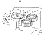
- FIG. 1 is a configuration diagram of an automatic analyzer according to an embodiment of the present invention.
- the automatic analyzer mainly includes a reagent system including a reagent dispensing pipetter 102 provided in the vicinity of each of two reagent disks 101 serving as reagent container storage units, and a sample dispensing pipettor 103 (specimen nozzle).
- a reaction system including a reaction disk 105 including a reaction vessel 104, a measurement system including a multiwavelength photometer 106 and an analog / digital (A / D) converter 107, and a control unit 112.
- an operation control system including a display input unit 114.
- the rack 115 in which the sample container 117 (sample container) is installed is transported to the sample suction position 108 by the transport unit 116.
- the sample dispensing pipetter 103 sucks a sample (also referred to as a specimen) in the sample container 117 and dispenses a predetermined amount into the reaction container 104 held on the reaction disk 105.
- the reaction container 104 into which the sample solution has been discharged and dispensed is moved to the first reagent addition position in the reaction disk 105 communicated with the thermostat 109.
- the reagent disk 101 moves so that the reagent container 110 corresponding to the current analysis item is positioned under the reagent dispensing pipetter 102 held by the lifting arm by the rotation operation.
- the predetermined first reagent sucked by the reagent dispensing pipetter 102 is added to the reaction container 104 moved to the first reagent addition position.
- the reaction vessel 104 after the addition of the first reagent is moved to the position of the stirring device 111, and the first stirring is performed by the stirring device 111.
- the luminous flux generated from the light source passes through the reaction vessel 104 in which the contents are agitated, and enters the multi-wavelength photometer 106. Then, the absorbance of the reaction liquid that is the contents of the reaction vessel 104 is detected by the multiwavelength photometer 106.
- the detected absorbance signal is supplied to a control unit (computer) 112 via an analog / digital (A / D) converter 107 and an interface, and is converted into an analysis item concentration to be measured in the sample solution.
- the display input unit 114 is a graphic user interface (GUI) that is connected to the control unit 112 and displays analysis results and operation screens. The operation can be performed by clicking a button displayed on the operation screen with a mouse or the like while the operation screen is displayed on the display input unit 114.
- GUI graphic user interface
- reaction vessel 104 After completion of the measurement, the reaction vessel 104 is moved to the position of the cleaning mechanism (not shown), and after the internal liquid is discharged at the cleaning position by the reaction vessel cleaning mechanism, it is washed with water and used for the next analysis. Is done.
- the sample dispensing pipettor 103 (specimen nozzle) collects a sample before dilution to be diluted and discharges it to the reaction vessel 104.
- the reagent dispensing pipetter 102 dispenses the diluted solution in the container set on the reagent disk 101 and discharges it to the reaction container 104 in which the sample before dilution is accommodated. Thereby, a high concentration sample is diluted and becomes a low concentration diluted sample (also referred to as a diluted specimen).
- the sample dispensing pipettor 103 separates this diluted sample and discharges it to another reaction vessel 104. Subsequent addition with a reagent, stirring, etc.
- the sample dispensing pipettor 103 has a function of dispensing the sample from the sample container 117 containing the sample and dispensing the diluted sample by the apparatus.
- the container containing the diluent may be provided in addition to the reagent disk 101.
- the cleaning process of the sample dispensing pipettor 103 will be described.
- the sample dispensing pipettor 103 is washed with a detergent, washing water or the like before sorting another sample in order to prevent contamination between different samples.
- the sample dispensing pipettor is cleaned by a cleaning mechanism (not shown).
- the control unit 112 controls each part of the apparatus such as drive control of the sample dispensing pipetter and control of the cleaning process of the sample dispensing pipetter.
- FIG. 2 shows an example of a process for planning a washing operation before collecting a diluted sample. The processing in FIG. 2 is performed for each analysis request regardless of the specimen.
- control unit 112 performs a process 201 for determining whether or not the next analysis item can be analyzed. “Analyzing is possible” means that the analysis can be carried out without any problems even if the analysis is started at the next sample collection timing, such as that there are enough consumables such as reagents used for the analysis and the reaction container can be used. It means that all the conditions are met.
- the process 202 for determining whether the next analysis item is dilution analysis is performed. As a result of the determination, if it is not a dilution analysis, it is not necessary to perform a washing operation before collecting a diluted sample, so the standard analysis assignment process 203 is performed and the planning process is terminated.
- a dilution analysis assignment process 204 is performed. Subsequently, a process 205 is performed to determine whether or not cleaning is required before collecting a diluted sample. If cleaning is required, the sample stored in the reaction container 104 is diluted at least several cycles after sample sampling from the sample container. Since it is clear that the sample is collected, the assignment process 206 for washing before the diluted sample is performed. Whether or not washing is necessary is determined by, for example, an analysis item of a diluted sample.
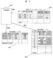
- FIG. 3 is a diagram showing an example of the software configuration of the assignment process 204 for dilution analysis, the process 205 for determining whether or not cleaning is required before collecting a diluted specimen, and the assignment process 206 for cleaning before diluted specimen preparation.
- the control unit 112 includes an analysis control program 301, an analysis parameter table 302, an analysis request table 303, and an analysis plan table 304.
- the analysis control program 301 searches the analysis request table 303 for an analysis request that has not been analyzed and has the highest priority, and determines an analysis request to be analyzed next.
- the analysis request includes dilution rate information indicating whether or not there is a request to perform dilution analysis.
- sample sorting control is assigned to a predetermined cycle of the analysis plan table 304.
- the analysis control program 301 refers to the analysis parameter table 302 and determines whether or not the analysis item to be measured next requires cleaning before diluted sample separation.
- cleaning control is assigned to a predetermined cycle of the analysis plan table 304. Note that the number of cycles between sample collection and diluted sample collection is determined for each analyzer.
- the analysis control program 301 refers to the analysis plan table 304 and executes the assigned control process for each cycle.
- the amount of detergent used may be determined based on the maximum dispensing amount of the nozzle, but in order to reduce consumption, it is determined based on the diluted sample dispensing amount of each item. Also good. Moreover, not only cleaning with detergent, but also a control for reducing the amount of water brought in by performing a drying process on the nozzle tip or the like may be performed.
- the sample fraction control is assigned to the second cycle of the analysis plan table 304, and the diluted sample fraction control is assigned to the sixth cycle.
- the analysis parameter table 302 it is understood that the analysis item of analysis ID0000002 requires cleaning with an alkaline detergent as cleaning before diluting sample collection. Thereby, the cleaning control is assigned to the fifth cycle of the analysis plan table 304. For example, if the diluted sample collection amount of the analysis item of analysis ID0000002 is 10 ⁇ L, 10 ⁇ L of alkaline detergent is consumed to clean the inside and outside of the sample nozzle.
- the analysis ID 0000002 is the same ID as the sample ID 10001, a high-concentration sample is obtained when the high-concentration sample separation process without dilution and the low-concentration sample separation process diluted by the apparatus are consecutive. It can be read from the analysis plan table that the detergent cleaning is planned between the preparative process and the low-concentration sample. Note that the term “continuous” as used herein is not limited to whether or not there is an empty cycle between the cycles, as long as the operation of actually separating the sample nozzles is continued. As shown in the example, this detergent cleaning is desirably performed in the previous cycle, which is immediately before the diluted specimen separation is performed.
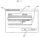
- FIG. 4 is an example of a screen for setting / changing whether or not to wash before diluted sample separation.
- the control unit 112 displays the pre-dilution pre-sorting cleaning setting screen 401.
- the pre-diluted sample pre-cleaning setting screen 401 includes a detergent setting list 402 that displays the item name and the type of detergent used before diluting the sample when performing dilution analysis on that item. Accordingly, the type of detergent used in the cleaning process can be selected for each analysis item from the detergent setting list 402.
- a detergent list 403 that displays settable detergents is displayed, and one of the detergents can be selected. In the example, only one detergent can be set, but a plurality of detergents may be selected in one item. It may also be possible to specify the number of cleanings.
- the diluted sample pre-sorting cleaning setting screen 401 includes an OK button 404, and can store detergent information by pressing the button.
- the set detergent information is reflected in the analysis parameter table 302.
- FIG. 5 is a flowchart showing an example of a process for planning a cleaning operation when the ratio between the immediately prior sample fraction and the diluted specimen fraction is greater than a certain value.
- control unit 112 performs processing 501 for determining whether or not the next analysis item can be analyzed. “Analyzing is possible” means that the analysis can be carried out without any problems even if the analysis is started at the next sample collection timing, such as that there are enough consumables such as reagents used for the analysis and the reaction container can be used. It means that all the conditions are met.
- processing 502 is performed to determine whether the next analysis item is dilution analysis. As a result of the determination, if the analysis is not a dilution analysis, it is not necessary to perform a washing operation before collecting the diluted specimen, so the standard analysis allocation process 503 is performed and the planning process is terminated. If it is a dilution analysis, a process 504 for determining whether or not cleaning is required before collecting a diluted specimen is performed. If cleaning is not necessary, a dilution analysis assignment process 505 is performed.
- the ratio of the dilution rate of the sample to be allocated is compared with the ratio of the dilution rate of the sample to be sampled immediately before that.
- the dilution ratio determination process 506 (Dilution ratio of the diluted sample fractionation process to be allocated / dilution ratio of the specimen to be fractionated immediately before) ⁇ Set value, it is determined that the cleaning process before the diluted specimen fractionation is unnecessary, and the dilution analysis allocation process 507 is performed.
- the dilution ratio determination process 506 if the ratio of the dilution ratio is equal to or higher than the set value, it is determined that contamination occurs because the concentration ratio of the diluted specimen is large, and the diluted specimen pre-sorting washing assignment 508 is performed.
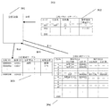
- FIG. 6 is a diagram showing an example of a software configuration for a process of planning a cleaning operation when the ratio between the immediately preceding sample sorting magnification and the diluted sample sorting magnification is greater than a certain value.
- the control unit 112 includes an analysis control program 601, an analysis parameter table 602, an analysis request table 603, and an analysis plan table 604.
- the analysis parameter table 602 includes a parameter for the cleaning dilution ratio required.
- control unit can analyze the analysis plan via the analysis control program 601. A plan is made so that a table like 604 is obtained.
- sample separation of analysis ID0000002 is assigned to cycle 2 and the diluted sample separation of analysis ID0000002 is assigned to cycle 6, if the sample separation processing of analysis ID0000003 is assigned to cycle 3, Sample collection and dilute sample collection in cycle 7 are continuous.
- the magnification ratio is 6.7 times.
- the item on the affected side is code 003, and the ratio of required dilution ratio is 5 times, which exceeds this value. Therefore, the analysis ID0000003 needs to be washed before collecting the diluted sample, so that the sample cannot be collected in cycle 3.
- analysis ID0000003 is assigned the sample collection in cycle 4, the washing in cycle 7, and the diluted sample collection in cycle 8. Since analysis ID0000002 and analysis ID0000003 are the same ID as sample ID10001, when the process of separating the diluted sample by the apparatus is continued between diluted samples of the same sample, the dilution rate of the immediately preceding sample and the immediately following sample It can be read from the analysis plan table that the detergent cleaning is planned to be performed during the fractionation process of these diluted specimens when the ratio of the dilution ratios of the specimens is a certain level or more.
- the setting value which is the detergent dilution ratio
- the ratio of the dilution factor that is the set value may be settable.
- the dilution ratio ratio determination processing 506 in FIG. 5 is YES and the pre-dilution pre-sorting cleaning assignment is not performed, it is determined that a retest is necessary from the measurement result of the diluted sample, and the retest is performed. There is a case. In the case of such re-examination, it is desirable to perform the detergent washing process before the previous sorting process without performing the dilution ratio determination process 506. This is because there was a possibility that it was judged as a re-examination because the detergent was not washed. Accordingly, in the measurement of each item, the sorting process performed immediately before the device sorts the diluted sample is stored, and if the detergent cleaning process according to FIGS. 5 and 6 is not performed, the retest is performed. It is desirable to perform detergent cleaning in which the sample nozzle is cleaned with a predetermined detergent between the sample sorting process and the previous sorting process.
- a detergent washing process is inserted in between. Desirably not. This is because a decrease in throughput due to the detergent cleaning process can be suppressed.
- the ratio of the dilution ratio of the immediately preceding specimen and the dilution ratio of the immediately following specimen is less than a certain value, it is desirable not to perform a detergent washing process between the fractionation processes of these diluted specimens. This is because a decrease in throughput due to the detergent cleaning process can be suppressed.
- the present invention can also be applied to the case where a diluted specimen is prepared in advance.
- the washing process may be performed when the magnification between the diluted specimens is a certain level or more.
- FIG. 7 is a diagram of the overall configuration of the automatic analyzer according to the second embodiment. The difference from FIG. 1 is that a plurality of sample dispensing pipettors 103 are provided. As shown in FIG. 7, a sample dispensing pipettor 103-A and a sample dispensing pipettor 103-B are provided.
- the automatic analyzer mainly includes a reagent system including two reagent disks 101 serving as reagent container storage units and a reagent dispensing pipetter 102 provided in the vicinity of each of the two reagent disks 101, and a sample.
- a sample system including a dispensing pipettor 103-A (specimen nozzle A) and a sample dispensing pipettor 103-B (specimen nozzle B), a reaction system including a reaction disk 105 including a reaction vessel 104, and a multi-wavelength luminous intensity
- the measurement system includes a total 106 and an analog / digital converter 107, and an operation control system including a control unit 112 and a display input unit 114.
- the rack 115 in which the sample container 117 (sample container) is installed is transported to the sample suction position 108 by the transport unit 116.
- the sample dispensing pipetter 103 sucks a sample (also referred to as a specimen) in the sample container 117 and dispenses a predetermined amount into the reaction container 104 held on the reaction disk 105.
- the sample dispensing pipettor 103 -B sucks the sample transferred to another sample dispensing position by the transport unit 116 and dispenses a predetermined amount into another reaction container 10 held on the reaction disk 105.
- the reagent dispensing pipettor 103-A and the sample dispensing pipettor 103-B have different times from when the sample is dispensed to the reaction vessel 10 until the reagent is dispensed to the same reaction vessel 10.
- sample dispensing B is added in the analysis plan table.
- the sample dispensing A corresponds to the sample dispensing pipettor 103 (103-A) in FIG. 1, and the sample dispensing B corresponds to the newly provided sample dispensing pipetter 103-B. Focusing on the fifth cycle, the sample dispensing pipettor 103-B can operate in the fifth cycle.
- the sample dispensing is performed using the sample dispensing pipettor 103-B so that the analysis item of the analysis ID 0000100 is measured. Control as follows. In this way, even if the sample dispensing pipettor 103-A is at the timing of detergent cleaning, the sample dispensing pipettor 103-B can sample the sample, so that one of the sample dispensing pipettors 103-A performs the detergent cleaning process. However, it is possible to suppress a decrease in the throughput of the apparatus.
- FIG. 9 an example of the software configuration is shown in FIG. 9 for the process of planning the washing operation when the magnification of the immediately preceding sample collection and the ratio of the diluted sample collection are above a certain level. Will be described. The description of the same part as in FIG. 6 is omitted. The difference is that the sample dispensing B is added in the analysis plan table. Also in this case, as in FIG. 8, if the sample is transferred to the sample dispensing position of the sample dispensing pipettor 103-B in cycle 7, the sample dispensing pipettor is used to measure the analysis item of analysis ID0000101. 103-B is used to control the sample separation.
- the sample dispensing pipettor 103-B can sample the sample, so that one of the sample dispensing pipettors 103-A performs the detergent cleaning process.
- sample dispensing pipettor 103-B also has the function of dispensing the diluted sample by the apparatus, the sample dispensed by the sample dispensing pipettor 103-A during the detergent cleaning of the sample dispensing pipettor 103-B. Sorting can be performed.
- the second sample nozzle is provided with a second sample nozzle for separating the sample from the sample container containing the sample, and the second sample nozzle performs the sample separation in the cycle in which the detergent cleaning process is performed. By doing so, it is possible to suppress a decrease in the throughput of the apparatus.
- the embodiment of the present invention has been described above. According to the present invention, it is possible to effectively reduce contamination from a high concentration sample without dilution to a diluted low concentration sample.
Landscapes
- Physics & Mathematics (AREA)
- Health & Medical Sciences (AREA)
- Life Sciences & Earth Sciences (AREA)
- Chemical & Material Sciences (AREA)
- Analytical Chemistry (AREA)
- Biochemistry (AREA)
- General Health & Medical Sciences (AREA)
- General Physics & Mathematics (AREA)
- Immunology (AREA)
- Pathology (AREA)
- Automatic Analysis And Handling Materials Therefor (AREA)
Abstract
Description
(割り付け対象の希釈検体分取処理の希釈倍率/直前で分取する検体の希釈倍率)<設定値
ならば希釈検体分取前の洗浄処理が不要と判断し、希釈分析割り付け処理507を行う。
102 試薬分注ピペッタ
103 試料分注ピペッタ
103-1 試薬分注ピペッタA
103-2 試薬分注ピペッタB
104 反応容器
105 反応ディスク
106 多波長光度計
107 アナログ/デジタル(A/D)コンバータ
108 試料吸引位置
109 恒温槽
110 試薬容器
111 攪拌装置
112 制御部
113 緊急ラック投入口
114 表示入力部
115 ラック
116 搬送部
117 試料容器
201、501 分析可能かどうかを判定する処理
202、502 希釈分析かどうかを判定する処理
203、503 標準分析の割付処理
204 希釈分析の割付処理
205、504 希釈検体分取前の洗浄要否を判定する処理
206 希釈検体分取前洗浄の割付処理
301、601 分析制御プログラム
302、602 分析パラメータテーブル
303、603 分析依頼テーブル
304、604 分析計画テーブル
401 希釈検体分取前洗浄設定画面
402 洗剤設定リスト
403 洗剤リスト
404 OKボタン
505 希釈分析割付処理
506 希釈倍率比判定処理
Claims (7)
- 検体を収容した検体容器から検体を分取するとともに、装置が希釈した検体を分取することを兼ね備えた検体ノズルと、
該検体ノズルを所定の洗剤にて洗浄する手段とを備え、
前記検体ノズルは、同一検体において、希釈を伴わない高濃度の検体の分取処理と、装置が希釈した低濃度の検体の分取処理が連続する場合において、高濃度の検体の分取処理と低濃度の検体の分取処理の間に、所定の洗剤により前記検体ノズルを洗浄する洗浄処理を行うことを特徴とする自動分析装置。 - 請求項1記載の自動分析装置において、
分析項目ごとに、前記洗浄処理で使用される洗剤の種類を少なくとも一つ以上設定可能な手段を備えたことを特徴とする自動分析装置。 - 請求項2記載の自動分析装置において、
さらに装置が希釈した検体を分取する処理が、同一検体の希釈検体間で連続する場合には、直前の検体の希釈倍率と直後の検体の希釈倍率の比が一定以上となる場合に、これらの希釈検体の分取処理の間に、洗剤により前記検体ノズルを洗浄する第2の洗浄処理を行うことを特徴とする自動分析装置。 - 請求項3記載の自動分析装置において、
前記希釈倍率の比を設定可能な手段を備えたことを特徴とする自動分析装置。 - 請求項3記載の自動分析装置において、
各項目の測定において、装置が希釈した検体を分取する直前に行われた分取処理を記憶し、前記第2の洗浄処理が行われていなければ、再検を行うための検体の分取処理と、この一つ前の分取処理との間に、所定の洗剤により前記検体ノズルを洗浄する第3の洗浄処理を行うことを特徴とする自動分析装置。 - 請求項1~5のいずれかに記載の自動分析装置において、
前記洗浄処理、前記第2の洗浄処理、前記第3の洗浄処理のいずれかの洗浄処理のうち、洗浄処理を行う条件が成立した場合でも、同一検体の分取処理が連続する場合は、洗浄処理を行わないように設定できる手段を備えたことを特徴とする自動分析装置。 - 請求項1~6のいずれかに記載の自動分析装置において、
さらに、検体を収容した検体容器から検体を分取する第2の検体ノズルを備え、前記洗浄処理を行うサイクルで、前記第2の検体ノズルは、検体の分取を行うことを特徴とする自動分析装置。
Priority Applications (4)
| Application Number | Priority Date | Filing Date | Title |
|---|---|---|---|
| EP13822477.9A EP2878956B1 (en) | 2012-07-25 | 2013-07-08 | Automated analyzer |
| CN201380038973.8A CN104508493B (zh) | 2012-07-25 | 2013-07-08 | 自动分析装置 |
| JP2014526841A JP6208127B2 (ja) | 2012-07-25 | 2013-07-08 | 自動分析装置 |
| US14/413,578 US9618526B2 (en) | 2012-07-25 | 2013-07-08 | Automated analyzer |
Applications Claiming Priority (2)
| Application Number | Priority Date | Filing Date | Title |
|---|---|---|---|
| JP2012-164300 | 2012-07-25 | ||
| JP2012164300 | 2012-07-25 |
Publications (1)
| Publication Number | Publication Date |
|---|---|
| WO2014017275A1 true WO2014017275A1 (ja) | 2014-01-30 |
Family
ID=49997091
Family Applications (1)
| Application Number | Title | Priority Date | Filing Date |
|---|---|---|---|
| PCT/JP2013/068582 Ceased WO2014017275A1 (ja) | 2012-07-25 | 2013-07-08 | 自動分析装置 |
Country Status (5)
| Country | Link |
|---|---|
| US (1) | US9618526B2 (ja) |
| EP (1) | EP2878956B1 (ja) |
| JP (1) | JP6208127B2 (ja) |
| CN (1) | CN104508493B (ja) |
| WO (1) | WO2014017275A1 (ja) |
Cited By (5)
| Publication number | Priority date | Publication date | Assignee | Title |
|---|---|---|---|---|
| CN106053772A (zh) * | 2015-04-14 | 2016-10-26 | 爱科来株式会社 | 生物体试样测定装置、生物体试样测定系统及生物体试样测定方法 |
| JP2017026480A (ja) * | 2015-07-23 | 2017-02-02 | 東芝メディカルシステムズ株式会社 | 自動分析装置 |
| US9897519B2 (en) | 2011-12-26 | 2018-02-20 | Hitachi High-Technologies Corporation | Automatic analyzer and method for washing sample-pipetting probe |
| JP2018204962A (ja) * | 2017-05-30 | 2018-12-27 | 日本電子株式会社 | 自動分析装置及びプログラム |
| JPWO2023021821A1 (ja) * | 2021-08-19 | 2023-02-23 |
Families Citing this family (8)
| Publication number | Priority date | Publication date | Assignee | Title |
|---|---|---|---|---|
| JP6208127B2 (ja) * | 2012-07-25 | 2017-10-04 | 株式会社日立ハイテクノロジーズ | 自動分析装置 |
| EP3133401A1 (de) * | 2015-08-18 | 2017-02-22 | Siemens Healthcare Diagnostics Products GmbH | Verfahren zur reinigung einer pipettiernadel in einem automatischen analysegerät |
| US10620093B2 (en) | 2015-12-23 | 2020-04-14 | Stryker Corporation | Sampling device for a medical sterilization device |
| JP2019066254A (ja) * | 2017-09-29 | 2019-04-25 | 株式会社安川電機 | 分注システム及び分注方法 |
| WO2020044781A1 (ja) * | 2018-08-28 | 2020-03-05 | 株式会社日立ハイテクノロジーズ | 自動分析装置、及びその方法 |
| CN109444443A (zh) * | 2018-10-15 | 2019-03-08 | 江苏天行健康科技有限公司 | 一种用于全自动农残检测仪的反应液搅拌清洗装置及工作方法 |
| JP6995085B2 (ja) * | 2019-05-31 | 2022-01-14 | 日本電子株式会社 | 自動分析装置及び自動分析装置の制御方法 |
| CN115524504B (zh) * | 2021-06-25 | 2025-02-18 | 深圳市帝迈生物技术有限公司 | 一种样本分析装置及其清洗方法、计算机可读存储介质 |
Citations (5)
| Publication number | Priority date | Publication date | Assignee | Title |
|---|---|---|---|---|
| JP2725917B2 (ja) * | 1991-10-04 | 1998-03-11 | アロカ株式会社 | 血液試料の分注方法 |
| JP2000055926A (ja) | 1999-03-24 | 2000-02-25 | Olympus Optical Co Ltd | 自動分析装置 |
| JP2005249585A (ja) * | 2004-03-04 | 2005-09-15 | Olympus Corp | 自動分析装置及び分析方法 |
| JP2008209339A (ja) * | 2007-02-28 | 2008-09-11 | Hitachi High-Technologies Corp | 自動分析装置 |
| JP2009288052A (ja) * | 2008-05-29 | 2009-12-10 | Toshiba Corp | 自動分析装置 |
Family Cites Families (15)
| Publication number | Priority date | Publication date | Assignee | Title |
|---|---|---|---|---|
| US4871682A (en) * | 1986-04-30 | 1989-10-03 | Baxter Travenol Laboratories, Inc. | Diluent carryover control |
| JP2834200B2 (ja) * | 1989-08-02 | 1998-12-09 | 株式会社日立製作所 | 液体試料の分析装置および分析方法 |
| US5610069A (en) * | 1992-03-27 | 1997-03-11 | Abbott Laboratories | Apparatus and method for washing clinical apparatus |
| US5314825A (en) * | 1992-07-16 | 1994-05-24 | Schiapparelli Biosystems, Inc. | Chemical analyzer |
| JP2001091523A (ja) * | 1999-09-21 | 2001-04-06 | Hitachi Ltd | 自動分析装置 |
| WO2008044312A1 (fr) * | 2006-10-13 | 2008-04-17 | Olympus Corporation | Procédé d'identification d'erreur et analyseur |
| JP5028350B2 (ja) * | 2008-07-11 | 2012-09-19 | 株式会社日立ハイテクノロジーズ | 自動分析装置 |
| JP2011106828A (ja) * | 2009-11-12 | 2011-06-02 | Hitachi High-Technologies Corp | 分注装置、自動分析装置及び分注方法 |
| JP5738526B2 (ja) * | 2009-12-04 | 2015-06-24 | 株式会社東芝 | 自動分析装置 |
| JP2011220928A (ja) * | 2010-04-13 | 2011-11-04 | Toshiba Corp | 自動分析装置 |
| JP2011257386A (ja) * | 2010-05-10 | 2011-12-22 | Toshiba Corp | 自動分析装置 |
| JP5836195B2 (ja) * | 2011-06-14 | 2015-12-24 | 日本電子株式会社 | 臨床検査用分析装置および臨床検査用分析装置における洗浄方法 |
| JP2011227092A (ja) * | 2011-07-05 | 2011-11-10 | Toshiba Corp | 自動分析装置 |
| EP2799887B1 (en) * | 2011-12-26 | 2017-08-30 | Hitachi High-Technologies Corporation | Automatic analyzer and method for washing sample-pipetting probe |
| JP6208127B2 (ja) * | 2012-07-25 | 2017-10-04 | 株式会社日立ハイテクノロジーズ | 自動分析装置 |
-
2013
- 2013-07-08 JP JP2014526841A patent/JP6208127B2/ja active Active
- 2013-07-08 EP EP13822477.9A patent/EP2878956B1/en active Active
- 2013-07-08 US US14/413,578 patent/US9618526B2/en active Active
- 2013-07-08 WO PCT/JP2013/068582 patent/WO2014017275A1/ja not_active Ceased
- 2013-07-08 CN CN201380038973.8A patent/CN104508493B/zh active Active
Patent Citations (5)
| Publication number | Priority date | Publication date | Assignee | Title |
|---|---|---|---|---|
| JP2725917B2 (ja) * | 1991-10-04 | 1998-03-11 | アロカ株式会社 | 血液試料の分注方法 |
| JP2000055926A (ja) | 1999-03-24 | 2000-02-25 | Olympus Optical Co Ltd | 自動分析装置 |
| JP2005249585A (ja) * | 2004-03-04 | 2005-09-15 | Olympus Corp | 自動分析装置及び分析方法 |
| JP2008209339A (ja) * | 2007-02-28 | 2008-09-11 | Hitachi High-Technologies Corp | 自動分析装置 |
| JP2009288052A (ja) * | 2008-05-29 | 2009-12-10 | Toshiba Corp | 自動分析装置 |
Cited By (8)
| Publication number | Priority date | Publication date | Assignee | Title |
|---|---|---|---|---|
| US9897519B2 (en) | 2011-12-26 | 2018-02-20 | Hitachi High-Technologies Corporation | Automatic analyzer and method for washing sample-pipetting probe |
| US11480504B2 (en) | 2011-12-26 | 2022-10-25 | Hitachi High-Tech Corporation | Automatic analyzer and method for washing sample-pipetting probe |
| CN106053772A (zh) * | 2015-04-14 | 2016-10-26 | 爱科来株式会社 | 生物体试样测定装置、生物体试样测定系统及生物体试样测定方法 |
| JP2017026480A (ja) * | 2015-07-23 | 2017-02-02 | 東芝メディカルシステムズ株式会社 | 自動分析装置 |
| JP2018204962A (ja) * | 2017-05-30 | 2018-12-27 | 日本電子株式会社 | 自動分析装置及びプログラム |
| JPWO2023021821A1 (ja) * | 2021-08-19 | 2023-02-23 | ||
| WO2023021821A1 (ja) * | 2021-08-19 | 2023-02-23 | 株式会社日立ハイテク | 自動分析装置および自動分析方法 |
| JP7672495B2 (ja) | 2021-08-19 | 2025-05-07 | 株式会社日立ハイテク | 自動分析装置および自動分析方法 |
Also Published As
| Publication number | Publication date |
|---|---|
| US9618526B2 (en) | 2017-04-11 |
| EP2878956A4 (en) | 2016-03-16 |
| JPWO2014017275A1 (ja) | 2016-07-07 |
| JP6208127B2 (ja) | 2017-10-04 |
| US20150153370A1 (en) | 2015-06-04 |
| CN104508493A (zh) | 2015-04-08 |
| EP2878956A1 (en) | 2015-06-03 |
| EP2878956B1 (en) | 2018-09-19 |
| CN104508493B (zh) | 2016-07-06 |
Similar Documents
| Publication | Publication Date | Title |
|---|---|---|
| JP6208127B2 (ja) | 自動分析装置 | |
| JP7399330B2 (ja) | 自動分析装置、及びその洗浄方法 | |
| JP4976870B2 (ja) | 自動分析装置及びプローブ洗浄方法 | |
| EP2034315B1 (en) | Automatic analyzer | |
| JP6585134B2 (ja) | 自動分析装置 | |
| JP6843800B2 (ja) | 自動分析装置、および自動分析方法 | |
| WO2016084462A1 (ja) | 自動分析装置 | |
| JP6198560B2 (ja) | 自動分析装置 | |
| WO2019176296A1 (ja) | 自動分析装置 | |
| JP5337600B2 (ja) | 自動分析装置及び自動分析装置の制御方法 | |
| JP5305794B2 (ja) | 自動分析装置 | |
| JP5271929B2 (ja) | 自動分析装置 | |
| JP6476003B2 (ja) | 自動分析システム | |
| JP2009281802A (ja) | 自動分析装置および検体検索システム | |
| JP4153171B2 (ja) | 生体サンプルの分析方法 | |
| JP4101466B2 (ja) | 生体サンプルの分析装置 | |
| JP5191954B2 (ja) | 臨床検査用自動分析装置 | |
| JPH07159416A (ja) | 自動化学分析装置 | |
| JP2001305145A (ja) | 自動分析装置 | |
| JP7245644B2 (ja) | 自動分析装置および自動分析方法 | |
| JP2010048827A (ja) | 自動分析装置 | |
| JP7672495B2 (ja) | 自動分析装置および自動分析方法 | |
| JP3845301B2 (ja) | 自動分析システム | |
| JP2016170075A (ja) | 自動分析装置及び自動分析方法 | |
| JP7768728B2 (ja) | 自動分析装置および方法 |
Legal Events
| Date | Code | Title | Description |
|---|---|---|---|
| 121 | Ep: the epo has been informed by wipo that ep was designated in this application |
Ref document number: 13822477 Country of ref document: EP Kind code of ref document: A1 |
|
| ENP | Entry into the national phase |
Ref document number: 2014526841 Country of ref document: JP Kind code of ref document: A |
|
| WWE | Wipo information: entry into national phase |
Ref document number: 2013822477 Country of ref document: EP |
|
| WWE | Wipo information: entry into national phase |
Ref document number: 14413578 Country of ref document: US |
|
| NENP | Non-entry into the national phase |
Ref country code: DE |