WO2014017435A1 - 送信装置、タイヤ状態監視システム、及びタイヤ組立体 - Google Patents
送信装置、タイヤ状態監視システム、及びタイヤ組立体 Download PDFInfo
- Publication number
- WO2014017435A1 WO2014017435A1 PCT/JP2013/069786 JP2013069786W WO2014017435A1 WO 2014017435 A1 WO2014017435 A1 WO 2014017435A1 JP 2013069786 W JP2013069786 W JP 2013069786W WO 2014017435 A1 WO2014017435 A1 WO 2014017435A1
- Authority
- WO
- WIPO (PCT)
- Prior art keywords
- tire
- sensor detection
- detection surface
- internal space
- vent hole
- Prior art date
- Legal status (The legal status is an assumption and is not a legal conclusion. Google has not performed a legal analysis and makes no representation as to the accuracy of the status listed.)
- Ceased
Links
Images






Classifications
-
- B—PERFORMING OPERATIONS; TRANSPORTING
- B60—VEHICLES IN GENERAL
- B60C—VEHICLE TYRES; TYRE INFLATION; TYRE CHANGING; CONNECTING VALVES TO INFLATABLE ELASTIC BODIES IN GENERAL; DEVICES OR ARRANGEMENTS RELATED TO TYRES
- B60C23/00—Devices for measuring, signalling, controlling, or distributing tyre pressure or temperature, specially adapted for mounting on vehicles; Arrangement of tyre inflating devices on vehicles, e.g. of pumps or of tanks; Tyre cooling arrangements
- B60C23/02—Signalling devices actuated by tyre pressure
-
- B—PERFORMING OPERATIONS; TRANSPORTING
- B60—VEHICLES IN GENERAL
- B60C—VEHICLE TYRES; TYRE INFLATION; TYRE CHANGING; CONNECTING VALVES TO INFLATABLE ELASTIC BODIES IN GENERAL; DEVICES OR ARRANGEMENTS RELATED TO TYRES
- B60C23/00—Devices for measuring, signalling, controlling, or distributing tyre pressure or temperature, specially adapted for mounting on vehicles; Arrangement of tyre inflating devices on vehicles, e.g. of pumps or of tanks; Tyre cooling arrangements
- B60C23/02—Signalling devices actuated by tyre pressure
- B60C23/04—Signalling devices actuated by tyre pressure mounted on the wheel or tyre
-
- B—PERFORMING OPERATIONS; TRANSPORTING
- B60—VEHICLES IN GENERAL
- B60C—VEHICLE TYRES; TYRE INFLATION; TYRE CHANGING; CONNECTING VALVES TO INFLATABLE ELASTIC BODIES IN GENERAL; DEVICES OR ARRANGEMENTS RELATED TO TYRES
- B60C23/00—Devices for measuring, signalling, controlling, or distributing tyre pressure or temperature, specially adapted for mounting on vehicles; Arrangement of tyre inflating devices on vehicles, e.g. of pumps or of tanks; Tyre cooling arrangements
- B60C23/02—Signalling devices actuated by tyre pressure
- B60C23/04—Signalling devices actuated by tyre pressure mounted on the wheel or tyre
- B60C23/0491—Constructional details of means for attaching the control device
- B60C23/0494—Valve stem attachments positioned inside the tyre chamber
Definitions
- the present invention relates to a transmission device that is provided in a tire cavity region and transmits tire information related to a tire state, a tire condition monitoring system using the transmission device, and a tire assembly.
- a puncture repair liquid that is injected into a tire cavity region sandwiched between a tire and a rim is often used. Since this puncture repair liquid is liquid, when the puncture repair liquid is injected into the tire cavity area, the puncture repair liquid is applied not only to the tire inner surface facing the tire cavity area but also to the transmitter provided in the tire cavity area. Adheres, and in some cases, solidifies and closes an opening provided in the transmission device, affecting the measurement of air pressure.
- a wheel state detection device capable of preventing a foreign substance from entering from a detection communication portion and maintaining a normal detection state
- Patent Document 1 a TPMS (Tire Pressure Monitoring System) valve of the wheel state detection device is provided with a communication portion opening / closing mechanism that opens and closes a communication hole provided in the case.
- the puncture repair liquid is restricted from entering the detection space through the communication hole.
- This communication portion opening / closing mechanism is constituted by a mechanical mechanism including a lid and a torsion coil spring, and the communication hole is automatically opened and closed by a centrifugal force acting on the wheel.
- the transmitter includes a sensor that detects, as tire information, the state of gas that fills the tire cavity region, a transmitter that wirelessly transmits the detected tire information, and a housing that includes a wall that covers the sensor and the transmitter And having.
- the housing includes an internal space defined from the tire cavity region by a wall of the housing.
- the casing is provided with a vent hole that penetrates the wall and communicates the internal space with the tire cavity region.
- the opening area of the outer opening on the surface of the casing facing the tire cavity region of the vent is 0.4 mm 2 or less, and the inner side of the vent on the surface of the casing facing the internal space The opening has a larger opening area than the outer opening.
- the communication portion opening / closing mechanism of the above-described wheel state detection device is constituted by a mechanical mechanism including a lid and a torsion coil spring, the device itself becomes complicated and costs increase.
- the transmission device of the tire information monitoring system even if the tire puncture is repaired using the puncture repair liquid, the tire information such as the tire pressure information can still be detected and transmitted appropriately, but the opening area of the outer opening portion Is 0.4 mm 2 or less, and fine and accurate processing is required.
- the present invention is a transmission device using a form different from the transmission device of the above-described tire information monitoring system, and even if a tire puncture is repaired using a puncture repair liquid, the tire still has tire pressure information and the like. It is an object of the present invention to provide a transmission device capable of appropriately detecting and transmitting information, a tire information monitoring system for determining whether there is a tire abnormality using the transmission device, and a tire assembly.
- One embodiment of the present invention is a transmission device that is provided in a tire cavity region and transmits tire information related to a tire state.
- the transmitter is A sensor having a planar sensor detection surface for sensing, as tire information, a gas state filled in a tire cavity region surrounded by a tire and a rim; A transmitter for wirelessly transmitting the detected tire information;
- a housing having an internal space in contact with the sensor detection surface of the sensor and a linearly extending air hole communicating with the internal space and the tire cavity region; .
- the inner opening of the ventilation hole facing the internal space faces a direction inclined with respect to the sensor detection surface, and is in any of the extending direction of the ventilation hole and the normal direction of the sensor detection surface. It is provided on the wall surface of the internal space extending in the orthogonal direction.
- An angle ⁇ between the extending direction of the air hole and the normal direction of the sensor detection surface is not less than 10 degrees and not more than 120 degrees.
- the tire assembly is Tires, A rim mounted on the tire; And a transmitting device that is provided in a tire cavity region between the tire and the rim and transmits tire information regarding the state of the tire.
- the transmitter is A sensor having a planar sensor detection surface for sensing, as tire information, a gas state filled in a tire cavity region surrounded by a tire and a rim; A transmitter for wirelessly transmitting the detected tire information;
- a housing having an internal space in contact with the sensor detection surface of the sensor and a linearly extending air hole communicating with the internal space and the tire cavity region; .
- the inner opening of the ventilation hole facing the internal space faces a direction inclined with respect to the sensor detection surface, and is in any of the extending direction of the ventilation hole and the normal direction of the sensor detection surface. It is provided on the wall surface of the internal space extending in the orthogonal direction.
- An angle ⁇ between the extending direction of the air hole and the normal direction of the sensor detection surface is not less than 10 degrees and not more than 120 degrees.
- the present invention is a tire condition monitoring system.
- the system includes a transmission device, a reception device, and a monitoring unit.
- the transmitter is A sensor having a planar sensor detection surface for sensing, as tire information, a gas state filled in a tire cavity region surrounded by a tire and a rim; A transmitter for wirelessly transmitting the detected tire information;
- a housing having an internal space in contact with the sensor detection surface of the sensor and a linearly extending air hole communicating with the internal space and the tire cavity region; .
- the inner opening of the vent facing the internal space faces a direction inclined with respect to the sensor detection surface, and extends in the direction in which the vent hole extends and in the normal direction of the sensor detection surface.
- the angle ⁇ between the extending direction of the vent hole and the normal direction of the sensor detection surface is provided on a wall surface of the internal space extending in a direction orthogonal to both. It is.
- the receiving device receives the tire information transmitted from the transmitter.
- the said monitoring part determines the presence or absence of abnormality of a tire based on the said tire information, and alert
- the sensor detection surface is obtained by projecting onto the inner wall surface of the internal space along the normal direction.
- the maximum height H 1 of the height in the inner wall of the interior space measured along the normal direction of the sensor detection surface as a reference the sensor higher than the maximum height H 2 of the of the height of the projection area, measured along the normal direction of the detection surface as a reference, it is preferable.
- the virtual extended portion of the vent hole is: It is preferable that it hits not the said sensor detection surface but the inner wall face which faced the said internal space of the said housing
- an outer opening portion of the ventilation hole facing the tire cavity region is formed from an outer wall surface of the housing. It is preferable that the protruding portion is provided on an inclined surface inclined with respect to the sensor detection surface.
- the internal space includes an inner wall surface of the protruding portion of the housing and the sensor detection surface.
- a space defined by the outer peripheral surface of the sensor is preferable.
- the transmitter, the transmission device of the tire assembly, and the transmission device of the system are connected to a tire valve that fills the tire with air.
- the center position of the air inlet on the tire cavity region side of the air introduced from the tire valve into the tire cavity region, the center position of the outer opening portion facing the tire cavity region of the vent hole, and the inner opening The center position of the portion is viewed in plan from a direction orthogonal to the sensor detection surface, passes through the center position of the outer opening, and from the center position of the air inlet to the center position of the outer opening.
- the center position of the inner opening is bounded by a virtual line that corresponds to the virtual plane when viewed in a plan view from a direction orthogonal to the sensor detection surface. It is preferable that the line is located on the same side as the center position of the air inlet.
- a maximum height region having a maximum height of an inner wall surface of the internal space measured with reference to the sensor detection surface Is between the inner opening of the vent hole and the sensor detection surface when the maximum height region, the vent hole and the sensor detection surface are viewed in a plan view from a direction orthogonal to the sensor detection surface. It is preferable that it is located in.
- the transmission device of the tire assembly, and the transmission device of the system a direction between a normal direction of the sensor detection surface and an outer direction in the tire radial direction of the tire is formed.
- the angle is preferably 0 to 15 degrees.
- the transmission device the tire assembly, and the tire condition monitoring system of the present invention, even if the tire puncture is repaired using the puncture repair liquid, the tire information such as the tire pressure information is still properly detected and the transmission device. Appropriate tire information can be transmitted.
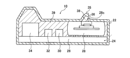
- FIG. 4 is a cross-sectional view of the transmitting device taken along the line AA shown in FIG. 3.
- It is a circuit block diagram of the transmission device shown in FIG.
- It is a circuit block diagram of the monitoring apparatus shown in FIG.
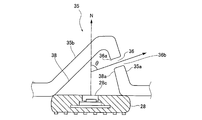
- It is the schematic diagram which expanded the periphery of the protrusion part shown in FIG.
- It is a figure explaining the state where the periphery of the protrusion part shown in FIG.
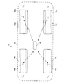
- FIG. 1 is a diagram showing an overall outline of a tire pressure monitoring system 10 which is an embodiment of a tire information monitoring system.
- a tire pressure monitoring system (hereinafter referred to as a system) 10 is mounted on a vehicle 12.
- the system 10 includes air pressure information transmitting devices (hereinafter referred to as transmitting devices) 16a, 16b, 16c, and 16d provided in tire hollow regions of the tires 14a, 14b, 14c, and 14d of the vehicle 12, and a monitoring device 18.
- transmitting devices air pressure information transmitting devices
- Each of the transmission devices 16a, 16b, 16c, and 16d detects, as tire information, information related to the pressure of air filled in a tire cavity region surrounded by the tire 14 and the rim 19 (see FIG. 2). Is transmitted to the monitoring device 18 wirelessly.
- the transmission devices 16a, 16b, 16c, and 16d are described together, the transmission devices 16a, 16b, 16c, and 16d are collectively referred to as the transmission device 16.
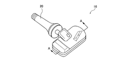
- FIG. 2 is a diagram illustrating an example of a tire assembly in which the transmission device 16 is fixed in the tire cavity region.
- FIG. 3 is a perspective view showing the entire device in which the transmission device 16 shown in FIG. 2 is integrated with the tire valve 20.
- the tire assembly includes a tire 14, a rim 19 and a transmission device 16.
- the rim 19 is attached to the tire 14.
- the transmission device 16 is provided in a tire cavity region between the tire 14 and the rim 19 and transmits tire information.
- the transmission device 16 is provided at an end portion of the tire valve 20 that extends toward the tire cavity region, and the tire valve 20 is mechanically fixed to the rim 19 as shown in FIG. It is fixed and arranged in the tire cavity region.
- the transmission device 16 includes a housing 22 that extends in the circumferential direction of the tire 14 (X direction in FIG. 2).
- the circumferential direction of the tire 14 refers to the rotation direction of the tread portion when the tread portion of the tire 14 is rotated around the tire rotation axis, that is, the rotation direction of the tire 14.
- the tire valve 20 is provided so as to extend in a direction (Y direction in FIG. 2) orthogonal to the circumferential rotation direction of the tire 14 (X direction in FIG. 2).
- the tire radial direction refers to a direction orthogonal to the X direction and the Y direction
- the outer direction in the tire radial direction refers to a direction away from the tire rotation axis.
- the transmission device 16 includes a housing 22 and a circuit 24 provided in the housing 22.
- the circuit 24 includes a substrate 26, a sensor unit 28 provided on the substrate 26, a transmitter 30, a processing unit 32, a power supply unit 34, and an antenna 40 (see FIG. 5).
- An internal space 38 is provided inside the housing 22.
- the sensor unit 28 has a sensor detection surface 28 c for detecting air pressure, and the sensor detection surface 28 c is a wall surface facing the internal space 38. Therefore, the sensor unit 28 can sense the pressure in the internal space 38.
- the casing 22 is provided with one vent hole 36 that communicates between the internal space 38 of the casing 22 and the tire cavity region so as to penetrate the wall of the casing 22.
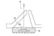
- the casing 22 is provided with a protruding portion 35 protruding from the outer wall surface on the outer wall surface, and an inner space 38 is provided inside the protruding portion 35.
- a vent hole 36 is provided on the inclined surface of the protruding portion 35 of the housing 22.
- the ventilation hole 36 is a hole that communicates the internal space 38 with the tire cavity region.
- the internal space 38 is defined by an outer peripheral surface including the inner wall surface of the protruding portion 35 of the housing 22 and the sensor detection surface 28 c of the sensor unit 28.
- the gap between the inner wall surface of the housing 22 and the circuit 24 is filled with the sealing resin 39 leaving the internal space 38. Even if a droplet of puncture repair liquid collides with the sensor detection surface 28c and adheres to the sensor detection surface 28c, the puncture repair liquid moves outward in the tire radial direction due to the centrifugal force generated by the rotation of the tire. As described above, the sensor detection surface 28c faces the outer side in the tire radial direction. In the present embodiment, the angle formed between the direction (normal direction) of the sensor detection surface 28c and the outer direction in the tire radial direction is preferably 0 degrees to 15 degrees.
- the sensor 28 is provided in the housing 22 with the angle of the normal direction of the sensor detection surface 28c with respect to the outer direction in the tire radial direction being 15 degrees as an upper limit.
- the cross-sectional area of the vent hole 36 provided in the protruding portion 35 of the housing 22 is constant along the extending direction of the vent hole 36.
- the inner opening of the ventilation hole 36 facing the internal space 38 is oriented in a direction inclined with respect to the sensor detection surface 28c, and is either in the extending direction of the ventilation hole 36 or the normal direction of the sensor detection surface 28c. It is provided on the wall surface of the internal space 38 extending in a direction orthogonal to the sheet (perpendicular to the paper surface of FIG. 4).
- the wall surface of the internal space 38 extending in a direction perpendicular to the paper surface of FIG. 4 includes a curved surface in addition to a plane extending in the direction perpendicular to the paper surface of FIG.
- the angle formed between the extending direction of the air hole 36 extending from the internal space 38 to the tire cavity region and the normal direction of the sensor detection surface 28c for sensing air of the sensor unit 28 is 10 degrees or more and 120 degrees or less. Preferably, it is 30 degrees or more and 120 degrees or less. The positional relationship among the vent hole 36, the internal space 38, and the sensor detection surface 28c will be described in detail later.
- FIG. 5 is a circuit configuration diagram of the transmission device 16.
- the sensor unit 28 includes an air pressure sensor 28a and an A / D converter 28b.
- the air pressure sensor 28a senses the air pressure in the internal space 38 in the housing 22 and outputs a pressure signal.
- the air pressure sensor 28a can sense the air pressure in the tire cavity region.
- the A / D converter 28b digitally converts the pressure signal output from the air pressure sensor 28a and outputs pressure data.
- the processing unit 32 includes a central processing unit 32a and a storage unit 32b.
- the central processing unit 32a operates based on a program stored in the semiconductor memory of the storage unit 32b.
- the pressure data sent from the sensor unit 28 is air pressure information to the monitoring device 18 via the transmitter 30 at predetermined time intervals, for example, every 5 minutes. Control to send pressure data.
- Identification information unique to the transmission device 16 is stored in the storage unit 32b in advance, and the central processing unit 32a controls to transmit the identification information together with the pressure data to the monitoring device 18.
- the storage unit 32b includes a ROM in which a program for operating the central processing unit 32a is recorded and a rewritable nonvolatile memory such as an EEPROM.
- the unique identification information of the transmission device 16 is stored in the non-rewritable area of the storage unit 32b.
- the transmitter 30 includes an oscillation circuit 30a, a modulation circuit 30b, and an amplification circuit 30c.
- the oscillation circuit 30a generates a carrier wave signal, for example, an RF signal having a frequency of 315 MHz band.
- the modulation circuit 30b modulates the carrier wave signal using the pressure data sent from the central processing unit 32a and the identification information unique to the transmission device 16 to generate a transmission signal.
- the modulation method methods such as amplitude shift keying (ASK), frequency modulation (FM), frequency shift keying (FSK), phase modulation (PM), phase shift keying (PSK) can be used.
- the amplifier circuit 30c amplifies the transmission signal generated by the modulation circuit 30b.
- the amplified transmission signal is wirelessly transmitted to the monitoring device 18 via the antenna 40.
- a secondary battery is used as the power supply unit 34 and supplies power to the sensor unit 28, the transmitter 30, and the processing unit 32.
- FIG. 6 is a circuit configuration diagram of the monitoring device 18.
- the monitoring device 18 is disposed, for example, at the position of the driver's seat of the vehicle 10 and notifies the driver of air pressure information.
- the monitoring device 18 includes an antenna 52, a reception unit 54, a reception buffer 56, a central processing unit 58, a storage unit 60, an operation unit 62, a switch 64, a display control unit 66, a display unit 68, Power supply unit 70.
- the antenna 52 is matched to the same frequency as the transmission frequency of the transmission device 16 and is connected to the reception unit 54.
- the receiving unit 54 receives a transmission signal of a predetermined frequency transmitted from the transmission device 16, performs demodulation processing, and extracts pressure data and identification information data. These data are output to the reception buffer 56.
- the reception buffer 56 temporarily stores pressure data and identification information data output from the reception unit 54.
- the stored pressure data and identification information data are output to the central processing unit 58 in accordance with instructions from the central processing unit 58.
- the central processing unit 58 is mainly composed of a CPU, and operates based on a program stored in the storage unit 60.
- the central processing unit 58 monitors the air pressures of the tires 14a to 14d for each identification information based on the received pressure data and identification information data. Specifically, the presence or absence of abnormality in the tires 14a to 14d is determined based on the pressure data, and the determination result is notified to the driver. Determining whether or not there is an abnormality in the tire means, for example, determining whether or not the tire is punctured because the air pressure becomes abnormally low or rapidly decreases in a short time.
- the central processing unit 58 outputs the determination result to the display control unit 66 and causes the display unit 68 to output the determination result via the display control unit 66. Furthermore, the central processing unit 58 performs initial settings such as a communication method with the transmission device 16 in accordance with information from the operation unit 62 and information from the switch 64. Further, based on information from the operation unit 62, a determination condition for determining whether there is a tire abnormality in the central processing unit 58 can be set.
- the storage unit 60 includes a ROM that stores a program for operating the CPU of the central processing unit 58 and a nonvolatile memory such as an EEPROM. The storage unit 60 stores a table of communication methods with the transmission device 16 at the manufacturing stage.
- the transmission device 16 and the monitoring device 18 communicate with each other using a communication method set in advance in the initial stage.
- the communication method table includes information such as a communication protocol, a transfer bit rate, and a data format corresponding to the unique identification information of each transmission device 16. Such information can be freely changed by input from the operation unit 62.
- the operation unit 62 includes an input device such as a keyboard and is used to input various information and conditions.
- the switch 64 is used to instruct the central processing unit 58 to start the initial setting.
- the display control unit 66 controls the display unit 68 to display the tire air pressure corresponding to the mounting positions of the tires 14a to 14d according to the determination result from the central processing unit 58. At that time, the display control unit 66 controls the display unit 68 to simultaneously display a determination result that the tire is in a puncture state.
- the power supply unit 70 controls the power supplied from the battery mounted on the vehicle 10 to a voltage suitable for each part of the monitoring device 18 and supplies the power through a power supply line (not shown). Thus, the transmission device 16 and the monitoring device 18 are configured.
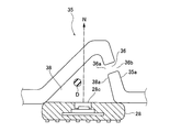
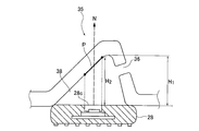
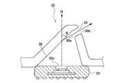
- FIG. 7 and 8 are schematic views illustrating the periphery of the protrusion 35 shown in FIG. 4 in an enlarged manner. 7 and 8, the protrusion 35 is shown larger than the sensor unit 28 in order to emphasize the protrusion 35.
- FIG. 8 illustrates a state in which the periphery of the protrusion 35 shown in FIG. 4 is enlarged and a droplet of puncture repair liquid has entered.
- the inner opening 36 a of the air hole 36 facing the internal space 38 is provided in the wall surface 38 a of the internal space 38.
- the wall surface 38a faces in a direction inclined with respect to the sensor detection surface 28c, and is orthogonal to both the extending direction of the vent hole 36 and the normal direction (N direction in FIG. 7) of the sensor detection surface 28c. It extends to. Further, the extending direction of the vent hole 36 from the internal space 38 to the tire cavity region (the direction of the arrow in FIG. 7) and the normal direction of the sensor detection surface 28c for sensing the air of the sensor unit 28 (in FIG. 7).
- the angle ⁇ (see FIG. 7) with respect to (N direction) is 10 degrees or more and 120 degrees or less.
- the ventilation hole 36 is provided on the inclined surface 35 a having a strong inclination among the inclined surfaces 35 a and 35 b of the protruding portion 35.
- the sensor detection surface 28c in FIG. 8 By using such a configuration of the vent hole 36, as shown in FIG. 8, even if the droplet D of the puncture repair liquid enters the internal space 38 through the vent hole 36, the sensor detection surface 28c in FIG.
- the droplet D hits the inner wall surface of the space 38 and collides with a place on the inner wall surface away from the sensor detection surface 28c and spreads in a film shape.
- the inner opening 36a faces in a direction inclined with respect to the sensor detection surface 28c, and extends in a direction orthogonal to both the extending direction of the vent hole 36 and the normal direction of the sensor detection surface 28c. 38, the portion of the puncture repair liquid spread in a film form on the wall surface of the internal space 38 having a sufficiently larger area than the inner opening 36a is unlikely to return to the inner opening 36a. Become. For this reason, the droplets D or the minute droplets in the internal space 38 are less likely to adhere to or around the inner opening 36a and block the vent hole 36.
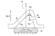
- FIG. 9 is a diagram more specifically showing the positional relationship between the vent hole 36, the internal space 38, and the sensor detection surface 28c.
- a region on the inner wall surface obtained by projecting the sensor detection surface 28c onto the inner wall surface of the inner space 38 along the normal direction N of the sensor detection surface 28c is defined as a projection region P (thick line portion in FIG. 9).
- the maximum height H 1 of the height of the inner wall surface of the internal space measured along the normal direction N with respect to the sensor detection surface 28c is along the normal direction N with reference to the sensor detection surface 28c. It is higher than the maximum height H 2 among the heights in the projection region P measured in the above.
- the droplet D is maximum as shown in FIG. Since they gather around the height H 1 and solidify at this position, the liquid droplet D is less likely to enter the air hole 36 from the inner opening 36a and solidify.
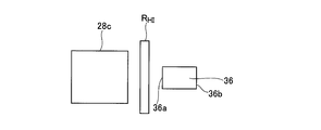
- a maximum height region R H1 having a maximum height among the heights of the inner wall surfaces of the internal space 38 measured with the sensor detection surface 28c as a reference is determined.
- the maximum height region R H1 , the vent hole 36, and the sensor detection plane 28 c are viewed in a plan view from a direction orthogonal to the sensor detection plane 28 c, the inner opening portion of the vent hole 36. It is preferably located between 36a and the sensor detection surface 28c.
- the virtual extended portion of the vent hole 36 not hit the sensor detection surface 28 c but the inner wall surface of the internal space 38.
- the droplet D that has entered the internal space 38 through the vent hole 36 often hits the inner wall surface of the internal space 38, and the droplet D does not directly adhere to the sensor detection surface 28 c from the vent hole 36 and solidify. Further, since the droplet D often hits the inner wall surface of the internal space 38, the droplet D spreads in a film shape at a location on the wall surface away from the sensor detection surface 28c.
- the puncture repair liquid spreads in a film shape on the wall surface of the internal space 38 having a sufficiently larger area than the inner opening 36 a, a part of the puncture repair liquid returns to the inner opening 36 a of the vent hole 36. Things will be less. For this reason, the droplet D enters the ventilation hole 36 from the inner opening 36a and is further solidified.
- the outer opening of the ventilation hole 36 facing the tire cavity region is inclined with respect to the sensor detection surface 28c of the protruding portion protruding from the outer wall surface of the housing 22. It is preferable to be provided on the inclined surface.
- the inclined surface includes a wall surface perpendicular to the sensor detection surface 28c.
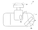
- FIG. 12 is a plan view of a more preferable example of the positional relationship between the vent hole, the internal space, and the sensor detection surface shown in FIG. 7 when viewed from the vertical direction with respect to the sensor detection surface 28c.
- the transmitter 30 is connected to a tire valve 20 that fills the tire 14 with air.
- the inner opening 36a are viewed in a plan view from a direction orthogonal to the sensor detection surface 28c.
- a virtual plane that is orthogonal to a straight line from the center position X of the air inlet 20a to the center position Y of the outer opening 36b and that passes through the center position Y of the outer opening 36b is assumed.
- the center position Z of the inner opening 36a is a boundary line of a virtual straight line ⁇ corresponding to a virtual plane when viewed in a plan view from a direction orthogonal to the sensor detection surface 28c. It is preferable that the air inlet 20a is located on the same side as the center position X.
- the virtual straight line ⁇ is a straight line passing through the center position Y of the outer opening 36b.
- the puncture repair liquid is introduced from the tire valve 20 through the air inlet 20a into the tire cavity region, so that the puncture repair liquid is vigorously punctured from the air inlet 20a of the transmitter 30 into the tire cavity region. Repair fluid is introduced.
- the air hole 36 so that the center position Z of the inner opening 36a of the air hole 36 is located on the same side as the center position X of the air introduction port 20a with the virtual straight line ⁇ as a boundary line, the air The puncture repair liquid introduced from the inlet 20a is less likely to directly adhere to the outer opening 36b of the vent hole 36 and further enter the vent hole 36.
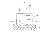
- FIGS. 13A to 13C are diagrams showing modifications 1, 2, and 3 of the present embodiment.
- the angle ⁇ between the extending direction of the vent hole 36 and the normal direction of the sensor detection surface 28c is 10 degrees or more and 120 degrees or less.
- the inner opening 36 a of the air hole 36 in contact with the internal space 38 faces the direction inclined with respect to the sensor detection surface 28 c and is orthogonal to the normal direction of the sensor detection surface 28 c and the extending direction of the air hole 36. It is provided on the wall surface 38a of the internal space extending in the direction. Therefore, it has the same effect as the above-described embodiment.
- a spherical protruding portion 35 protruding from the outer wall surface of the housing 22 is provided on the outer wall surface.
- the inner wall surface 38 of the spherical protrusion 35 is a spherical wall surface of the inner space 38, and this wall surface is at least in the direction perpendicular to the normal direction of the sensor detection surface 28 c and the extending direction of the vent hole 36. It extends. That is, the wall surface 38a of the internal space extending in the direction perpendicular to the normal direction of the sensor detection surface 28c and the extending direction of the vent hole 36 includes a spherical wall surface.
- a protruding portion 35 protruding from the outer wall surface of the housing 22 is provided on the outer wall surface.
- the protrusion 35 extends in the direction perpendicular to the paper surface of FIG. 13B.
- the maximum height H 1 among the heights on the inner wall surface of the internal space is the maximum height among the heights in the projection region P measured along the normal direction N with reference to the sensor detection surface 28c. Higher than H 2 .
- the puncture repair liquid is captured in the maximum height region R H1 as shown in FIG. I can't do it.
- the inner opening 36a of the air hole 36 in contact with the internal space 38 faces a direction inclined with respect to the sensor detection surface 28c, and is orthogonal to the normal direction of the sensor detection surface 28c and the extending direction of the air hole 36. It is provided on the wall surface 38a of the internal space extending in the direction. For this reason, as in the above-described embodiment, it is very unlikely that a part of the puncture repair liquid returns to the inner opening 36a.
- the outer opening 36b of the protrusion 35 of the housing 22 is surrounded by a protrusion 35c.
- the projection 35 c causes the outer opening 36 b to enter the outer opening 36 b. I can't get closer. For this reason, the protrusion 35c can prevent the tire puncture repair liquid from entering the vent hole 36.
- FIG. 13D is a diagram showing a fourth modification.
- the protrusion part 35 is extended in the paper surface perpendicular
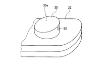
- FIG. 13E and FIG. 13F are diagrams showing a fifth modification.
- the protruding portion 35 protrudes in a cylindrical shape, but the surface 35 a at the protruding tip is inclined with respect to the outer wall surface of the housing 22.
- the inner opening 36a of the air hole 36 facing the internal space 38 is erected (inclined) in a direction perpendicular to the sensor detection surface 28c, and the extending direction of the air hole 36 and sensor detection are provided. It is provided on the wall surface of the internal space 38 that extends in a direction orthogonal to any of the normal directions N of the surface 28c (perpendicular direction in FIG. 13F).
- the surface on which the inner opening 36a of the vent hole 36 in Modification 5 is provided is a side surface curved into a cylindrical curved surface, but extends in the direction perpendicular to the paper surface of FIG. 13F.
- This curved curved surface is also included in the wall surface of the internal space 38 extending in a direction orthogonal to both the extending direction of the vent hole 36 and the normal direction N of the sensor detection surface 28c.
- the angle ⁇ between the extending direction of the vent hole 36 and the normal direction N of the sensor detection surface 28c in Modification 5 is 90 degrees. Therefore, the modification 5 also has the same effect as the embodiment shown in FIG. 7 described above.
- the transmitting device 16 was provided in the tire cavity region of the 195 / 65R15 tire 14, and puncture repair liquid was injected into the tire cavity region.
- the air pressure of the tire 14 was 200 kPa.
- the tire 14 was subjected to a traveling test at 30 km / hour using an indoor drum test. The travel of 30 minutes was defined as one travel step, the travel was stopped after each travel step, the tire air pressure was reduced by 50 kPa, and the tire air pressure was measured.
- the air pressure was acquired using the monitoring device 18.
- the correct air pressure is detected, that is, when the pressure data indicates that the pressure has decreased by 50 kPa, the air pressure is increased by 50 kPa to return to the original state, and the vehicle is run again.
- FIG. 14 is a diagram for explaining the positional relationship among the vent hole 36, the internal space 38, and the sensor detection surface 28a used in the third comparative example.
- the sensor is provided so that the normal direction of the sensor detection surface is the outer side of the tire radial direction.
Landscapes
- Engineering & Computer Science (AREA)
- Mechanical Engineering (AREA)
- Measuring Fluid Pressure (AREA)
- Arrangements For Transmission Of Measured Signals (AREA)
- Tires In General (AREA)
Description
具体的には、車輪状態検出装置のTPMS(Tire Pressure Monitoring System)バルブには、ケースに設けられた連通孔を開閉する連通部開閉機構が設けられている。パンク修理の際にそのパンク修理液が連通孔を介して検出空間に侵入するのが規制される。この連通部開閉機構は、蓋体およびねじりコイルばねを含むメカ的機構により構成され、車輪に作用する遠心力により連通孔が自動的に開閉されるようになっている。
当該送信装置は、タイヤ空洞領域に充填される気体の状態を、タイヤ情報として検出するセンサと、検出したタイヤ情報を無線により送信する送信機と、センサおよび送信機を覆う壁を備えた筐体と、を有する。筐体は、筐体の壁によりタイヤ空洞領域から画された内部空間を備える。この筐体には、壁を貫通して内部空間とタイヤ空洞領域とを連通する通気孔が設けられている。このとき、通気孔の、タイヤ空洞領域に面する筐体の表面における外側開口部の開口面積は、0.4mm2以下であり、この通気孔の、内部空間に面した筐体の表面における内側開口部は、外側開口部に比べて開口面積が広い。
一方、タイヤ情報監視システムの送信装置では、パンク修理液を用いてタイヤのパンクを修理しても、依然としてタイヤの空気圧情報等のタイヤ情報を適切に検出し送信できるが、外側開口部の開口面積は0.4mm2以下あるため、微細で正確な加工が必要である。
タイヤとリムで囲まれたタイヤ空洞領域に充填される気体の状態をタイヤ情報として感知する平面状のセンサ検出面を有するセンサと、
検出した前記タイヤ情報を無線により送信する送信機と、
前記センサと前記送信機が内部に設けられ、前記センサの前記センサ検出面に接する内部空間と、前記内部空間と前記タイヤ空洞領域を連通する直線状に延びた通気孔と、を有する筐体と、を備える。
前記内部空間に面する前記通気孔の内側開口部は、前記センサ検出面に対して傾斜した方向を向き、かつ、前記通気孔の延在方向及び前記センサ検出面の法線方向のいずれにも直交する方向に延びる前記内部空間の壁面に設けられる。
前記通気孔の前記延在方向と、前記センサ検出面の前記法線方向との間の角度θが、10度以上120度以下である。
タイヤと、
前記タイヤに装着されたリムと、
前記タイヤと前記リムの間のタイヤ空洞領域に設けられた、タイヤの状態に関するタイヤ情報を送信する送信装置と、を備える。
前記送信装置は、
タイヤとリムで囲まれたタイヤ空洞領域に充填される気体の状態をタイヤ情報として感知する平面状のセンサ検出面を有するセンサと、
検出した前記タイヤ情報を無線により送信する送信機と、
前記センサと前記送信機が内部に設けられ、前記センサの前記センサ検出面に接する内部空間と、前記内部空間と前記タイヤ空洞領域を連通する直線状に延びた通気孔と、を有する筐体と、を備える。
前記内部空間に面する前記通気孔の内側開口部は、前記センサ検出面に対して傾斜した方向を向き、かつ、前記通気孔の延在方向及び前記センサ検出面の法線方向のいずれにも直交する方向に延びる前記内部空間の壁面に設けられる。
前記通気孔の前記延在方向と、前記センサ検出面の前記法線方向との間の角度θが、10度以上120度以下である。
前記システムは、送信装置と、受信装置と、監視部と、を備える。
前記送信装置は、
タイヤとリムで囲まれたタイヤ空洞領域に充填される気体の状態をタイヤ情報として感知する平面状のセンサ検出面を有するセンサと、
検出した前記タイヤ情報を無線により送信する送信機と、
前記センサと前記送信機が内部に設けられ、前記センサの前記センサ検出面に接する内部空間と、前記内部空間と前記タイヤ空洞領域を連通する直線状に延びた通気孔と、を有する筐体と、を備える。
このとき、前記内部空間に面する前記通気孔の内側開口部は、前記センサ検出面に対して傾斜した方向を向き、かつ、前記通気孔の延在方向及び前記センサ検出面の法線方向のいずれにも直交する方向に延びる前記内部空間の壁面に設けられ、前記通気孔の前記延在方向と、前記センサ検出面の前記法線方向との間の角度θが、10度以上120度以下である。
前記受信装置は、前記送信機から送信された前記タイヤ情報を受信する。
前記監視部は、前記タイヤ情報に基づいて、タイヤの異常の有無を判定し、判定結果を報知する。
前記タイヤバルブから前記タイヤ空洞領域に導入される空気の前記タイヤ空洞領域側の空気導入口の中心位置と、前記通気孔の前記タイヤ空洞領域に面する外側開口部の中心位置と、前記内側開口部の中心位置を、前記センサ検出面に対して直交する方向から平面視して見るとともに、前記外側開口部の中心位置を通り、前記空気導入口の中心位置から前記外側開口部の中心位置に向かう直線に直交する仮想平面を想定したとき、前記内側開口部の中心位置は、前記センサ検出面に対して直交する方向から平面視して見たときの前記仮想平面に対応する仮想直線を境界線にして前記空気導入口の中心位置と同じ側に位置する、ことが好ましい。
図1は、タイヤ情報監視システムの実施形態であるタイヤ空気圧モニタリングシステム10の全体概要を示す図である。
タイヤ空気圧モニタリングシステム(以下、システムという)10は、車両12に搭載されている。システム10は、車両12の各タイヤ14a,14b,14c,14dのタイヤ空洞領域に設けられた空気圧情報送信デバイス(以下、送信デバイスという)16a,16b,16c,16dと、監視装置18と、を有する。
図2は、送信デバイス16がタイヤ空洞領域内に固定されたタイヤ組立体の一例を説明する図である。図3は、図2に示す送信デバイス16がタイヤバルブ20と一体化したデバイス全体を示す斜視図である。
タイヤ組立体は、タイヤ14とリム19と送信デバイス16を含む。リム19はタイヤ14に装着される。送信デバイス16は、後述するように、タイヤ14とリム19の間のタイヤ空洞領域に設けられ、タイヤ情報を送信する。
具体的には、送信デバイス16は、タイヤ空洞領域の側に延びるタイヤバルブ20の端部に設けられ、図2に示すように、タイヤバルブ20がリム19に機械的に固定されることにより、タイヤ空洞領域内に固定されて配置される。また、送信デバイス16は、タイヤ14の周方向(図2のX方向)に延びる筐体22を有する。ここで、タイヤ14の周方向とは、タイヤ回転軸の周りにタイヤ14のトレッド部を回転させたときのトレッド部の回転方向、すなわちタイヤ14の回転方向をいう。
また、本実施形態では、タイヤバルブ20は、タイヤ14の周方向の回転方向(図2のX方向)に直交する方向(図2のY方向)に延びるように設けられる。タイヤ径方向は、X方向及びY方向に直交する方向をいい、タイヤ径方向の外側方向は、タイヤの回転軸から離れる方向をいう。
センサユニット28は、空気圧を検出するためのセンサ検出面28cを有し、センサ検出面28cは、内部空間38に面する壁面となっている。したがって、センサユニット28は、内部空間38の圧力を感知することができる。
筐体22の突出部35に設けられた通気孔36の断面積は通気孔36の延在方向に沿って一定である。内部空間38に面する通気孔36の内側開口部は、センサ検出面28cに対して傾斜した方向に向き、かつ、通気孔36の延在方向及びセンサ検出面28cの法線方向のいずれにも直交する方向(図4の紙面に対して垂直方向)に延びる内部空間38の壁面に設けられている。ここで、図4の紙面に対して垂直方向に延びる内部空間38の壁面は、図4の紙面に対して垂直方向に延びる平面の他、曲面を含む。さらに、通気孔36の、内部空間38からタイヤ空洞領域に延びる延在方向と、センサユニット28の空気を感知するセンサ検出面28cの法線方向との間の成す角度は10度以上120度以下、好ましくは、30度以上120度以下となっている。通気孔36、内部空間38及びセンサ検出面28cとの間の位置関係については、以降で詳細に説明する。
センサユニット28は、空気圧センサ28aとA/D変換器28bを有する。空気圧センサ28aは、筐体22内の内部空間38の空気圧を感知し、圧力信号を出力する。ここで、内部空間38は、通気孔36を介してタイヤ空洞領域と連通しているため、空気圧センサ28aは、タイヤ空洞領域の空気圧を感知することができる。
A/D変換器28bは、空気圧センサ28aから出力された圧力信号をデジタル変換し、圧力データを出力する。
発振回路30aは、搬送波信号、例えば315MHz帯の周波数のRF信号を生成する。
変調回路30bは、中央処理部32aから送られた圧力データと送信デバイス16に固有の識別情報とを用いて、搬送波信号を変調して送信信号を生成する。変調方式は、振幅偏移変調(ASK)、周波数変調(FM)、周波数偏移変調(FSK)、位相変調(PM)、位相偏移変調(PSK)等の方式を用いることができる。
増幅回路30cは、変調回路30bで生成された送信信号を増幅する。増幅された送信信号は、アンテナ40を介して、監視装置18に無線で送信される。
電源部34は、例えば二次バッテリが用いられ、センサユニット28と、送信機30と、処理ユニット32と、に電力を供給する。
図6は、監視装置18の回路構成図である。
監視装置18は、例えば車両10の運転席の位置に配置され、運転者に空気圧の情報を報知する。監視装置18は、アンテナ52と、受信部54と、受信バッファ56と、中央処理部58と、記憶部60と、操作部62と、スイッチ64と、表示制御部66と、表示部68と、電源部70と、を有する。
受信部54は、送信デバイス16から送信された所定の周波数の送信信号を受信し、復調処理をして圧力データと識別情報のデータを取り出す。これらのデータは、受信バッファ56に出力される。
受信バッファ56は、受信部54から出力された圧力データと識別情報のデータを一時的に格納する。格納された圧力データと識別情報のデータは、中央処理部58からの指示にしたがって、中央処理部58に出力される。
さらに、中央処理部58は、操作部62からの情報やスイッチ64からの情報に応じて、送信デバイス16との間の通信方式等の初期設定を行う。また、操作部62からの情報により、中央処理部58においてタイヤの異常の有無の判定を行うための判定条件を設定することもできる。
記憶部60は、中央処理部58のCPUを動作するプログラムが記憶されたROMと、EEPROM等の不揮発性メモリとを有する。この記憶部60には、製造段階で、送信デバイス16との間の通信方式のテーブルが記憶されている。送信デバイス16と監視装置18は、初期段階において予め設定されている通信方式で通信する。通信方式テーブルには、送信デバイス16のそれぞれの固有の識別情報に対応して、通信プロトコル、転送ビットレート、データフォーマット等の情報が含まれている。これらの情報は、操作部62からの入力により自在に設定変更をすることができる。
表示制御部66は、中央処理部58からの判定結果に応じて、タイヤ14a~14dの装着位置に対応させてタイヤの空気圧を表示部68に表示させるように制御する。その際、表示制御部66は、タイヤがパンク状態にあるといった判定結果も、表示部68に同時に表示させるように制御する。
電源部70は、車両10に搭載されているバッテリから供給された電力を、監視装置18の各部分に適した電圧に制御して、図示されない電源ラインを通して電力を供給する。
このように、送信デバイス16と監視装置18は構成される。
図7,8は、図4に示す突出部35周辺を拡大して記した模式図である。図7,8では、突出部35を強調するために、突出部35はセンサユニット28に比べて大きく記している。図8は、図4に示す突出部35の周辺を拡大して、パンク修理液の液滴が進入した状態を説明している。
図13A~13Cは、本実施形態の変形例1,2,3を示す図である。変形例1~3は、いずれも、通気孔36の延在方向とセンサ検出面28cの法線方向との間の角度θが、10度以上120度以下である。さらに、内部空間38に接する通気孔36の内側開口部36aは、センサ検出面28cに対して傾斜した方向を向き、かつセンサ検出面28cの法線方向と通気孔36の延在方向に直交する方向に延びた内部空間の壁面38aに設けられている。したがって、上述した本実施形態と同様の効果を有する。
本実施形態の効果を調べるために、筐体22の通気孔36の形態を種々変更して、正しい空気圧の測定ができなくなるまでのタイヤの走行時間を調べた。

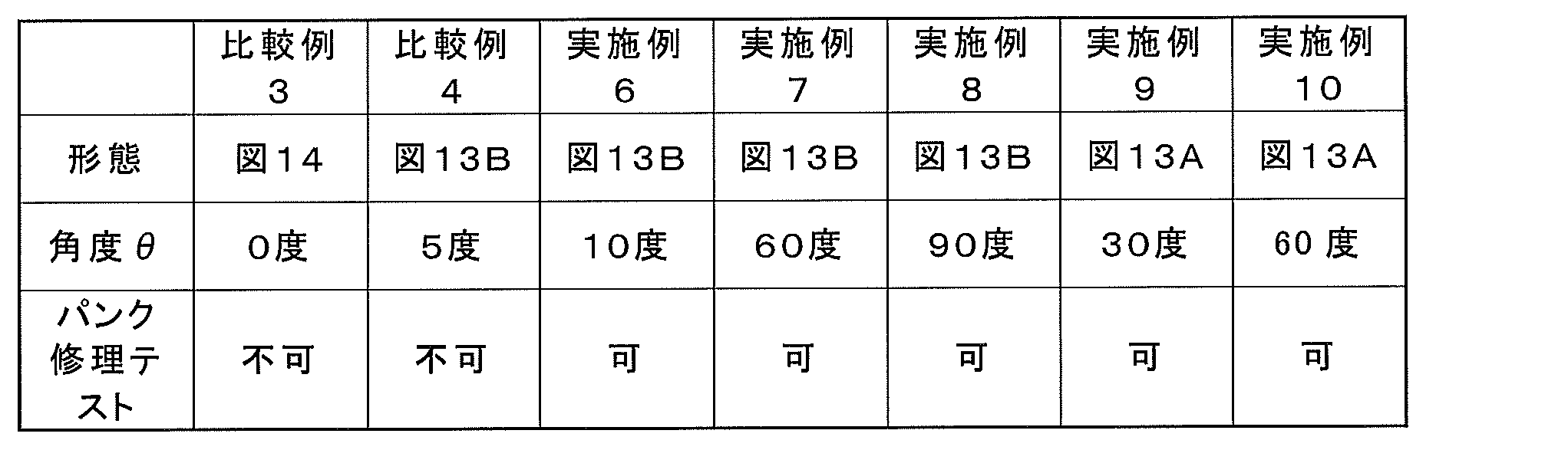
以上より、通気孔36の形態が、図7に示す形態あるいは図13Bに示す形態であっても、角度θを10度以上120度以下とすることにより、パンク修理テストが合格レベルになることがわかる。図13Aに示す形態においても、角度θを10度以上120度以下とする実施例9,10は、パンク修理テストが合格レベルになっている。
これより、本実施形態の効果は明らかである。
12 車両
14,14a,14b,14c,14d タイヤ
16,16a,16b,16c,16d 空気圧情報送信デバイス
18 監視装置
19 リム
20 タイヤバルブ
22 筐体
24 回路
26 基板
28 センサユニット
28a センサ検出面
28b A/D変換器
28c センサ検出面
30 送信機
32 処理ユニット
34 電源部
35 突出部
35a,35b 傾斜面
35c 突起
36 通気孔
36a 内側開口部
36b 外側開口部
38 内部空間
38a 壁面
40,52 アンテナ
54 受信部
56 受信バッファ
58 中央処理部
60 記憶部
62 操作部
64 スイッチ
66 表示制御部
68 表示部
70 電源部
Claims (16)
- タイヤ空洞領域に設けられ、タイヤの状態に関するタイヤ情報を送信する送信装置であって、
タイヤとリムで囲まれたタイヤ空洞領域に充填される気体の状態をタイヤ情報として感知する平面状のセンサ検出面を有するセンサと、
検出した前記タイヤ情報を無線により送信する送信機と、
前記センサと前記送信機が内部に設けられ、前記センサの前記センサ検出面に接する内部空間と、前記内部空間と前記タイヤ空洞領域を連通する直線状に延びた通気孔と、を有する筐体と、を備え、
前記内部空間に面する前記通気孔の内側開口部は、前記センサ検出面に対して傾斜した方向を向き、かつ、前記通気孔の延在方向及び前記センサ検出面の法線方向のいずれにも直交する方向に延びる前記内部空間の壁面に設けられ、
前記通気孔の前記延在方向と、前記センサ検出面の前記法線方向との間の成す角度θが、10度以上120度以下である、
ことを特徴とする送信装置。 - 前記センサ検出面を、前記法線方向に沿って前記内部空間の内壁面に投射して得られる前記内壁面上の領域を投射領域としたとき、
前記センサ検出面を基準として前記法線方向に沿って測った前記内部空間の内壁面における高さのうちの最大高さH1は、前記センサ検出面を基準として前記法線方向に沿って測った前記投射領域における高さのうちの最大高さH2に比べて高い、請求項1に記載の送信装置。 - 前記通気孔を前記内部空間に仮想的に延長したとき、仮想した前記通気孔の延長部分は、前記センサ検出面ではなく、前記筐体の前記内部空間に面した内壁面に当たる、請求項1または2に記載の送信装置。
- 前記通気孔の前記タイヤ空洞領域に面する外側開口部は、前記筐体の外壁面から突出した突出部の、前記センサ検出面に対して傾斜した傾斜面に設けられている、請求項1~3のいずれか1項に記載の送信装置。
- 前記内部空間は、前記筐体の前記突出部における内壁面と、前記センサ検出面を含む前記センサの外周面とにより区画された空間である、請求項4に記載の送信装置。
- 前記送信機は、タイヤに空気を充填するタイヤバルブに連結されて設けられ、
前記タイヤバルブから前記タイヤ空洞領域に導入される空気の前記タイヤ空洞領域側の空気導入口の中心位置と、前記通気孔の前記タイヤ空洞領域に面する外側開口部の中心位置と、前記内側開口部の中心位置を、前記センサ検出面に対して直交する方向から平面視して見るとともに、前記空気導入口の中心位置から平面視した前記外側開口部の中心位置に向かう直線に直交する仮想平面であって、平面視した前記外側開口部の中心位置を通る仮想平面を想定したとき、
前記内側開口部の中心位置は、前記センサ検出面に対して直交する方向から平面視して見たときの前記仮想平面に対応する仮想直線を境界にして前記空気導入口の中心位置と同じ側に位置する、請求項1~5のいずれか1項に記載の送信装置。 - 前記センサ検出面を基準として測った前記内部空間の内壁面の高さのうち、最大高さを有する最大高さ領域は、前記センサ検出面に直交する方向から平面視して前記最大高さ領域、前記通気孔及び前記センサ検出面を見たとき、前記通気孔の前記内側開口部と前記センサ検出面との間に位置する、請求項1~6のいずれか1項に記載の送信装置。
- タイヤ状態監視システムであって、
前記システムは、送信装置と、受信装置と、監視部と、を備え、
前記送信装置は、
タイヤとリムで囲まれたタイヤ空洞領域に充填される気体の状態をタイヤ情報として感知する平面状のセンサ検出面を有するセンサと、
検出した前記タイヤ情報を無線により送信する送信機と、
前記センサと前記送信機が内部に設けられ、前記センサの前記センサ検出面に接する内部空間と、前記内部空間と前記タイヤ空洞領域を連通する直線状に延びた通気孔と、を有する筐体と、を備え、
前記内部空間に面する前記通気孔の内側開口部は、前記センサ検出面に対して傾斜し、かつ、前記通気孔の延在方向及び前記センサ検出面の法線方向のいずれにも直交する方向に延びる前記内部空間の壁面に設けられ、
前記通気孔の前記延在方向と、前記センサ検出面の前記法線方向との間の成す角度θが、10度以上120度以下であり、
前記受信装置は、前記送信機から送信された前記タイヤ情報を受信し、
前記監視部は、前記タイヤ情報に基づいて、タイヤの異常の有無を判定し、判定結果を報知する、ことを特徴とするタイヤ状態監視システム。 - タイヤ組立体であって、
タイヤと、
前記タイヤに装着されたリムと、
前記タイヤと前記リムの間のタイヤ空洞領域に設けられた、タイヤの状態に関するタイヤ情報を送信する送信装置と、を備え、
前記送信装置は、
タイヤとリムで囲まれたタイヤ空洞領域に充填される気体の状態をタイヤ情報として感知する平面状のセンサ検出面を有するセンサと、
検出した前記タイヤ情報を無線により送信する送信機と、
前記センサと前記送信機が内部に設けられ、前記センサの前記センサ検出面に接する内部空間と、前記内部空間と前記タイヤ空洞領域を連通する直線状に延びた通気孔と、を有する筐体と、を備え、
前記内部空間に面する前記通気孔の内側開口部は、前記センサ検出面に対して傾斜した方向を向き、かつ、前記通気孔の延在方向及び前記センサ検出面の法線方向のいずれにも直交する方向に延びる前記内部空間の壁面に設けられ、
前記通気孔の前記延在方向と、前記センサ検出面の前記法線方向との間の成す角度θが、10度以上120度以下である、
ことを特徴とするタイヤ組立体。 - 前記センサ検出面の法線方向と、前記タイヤのタイヤ径方向の外側方向との間の成す角度は0度~15度である、請求項9に記載のタイヤ組立体。
- 前記センサ検出面を、前記法線方向に沿って前記内部空間の内壁面に投射して得られる前記内壁面上の領域を投射領域としたとき、
前記センサ検出面を基準として前記法線方向に沿って測った前記内部空間の内壁面における高さのうちの最大高さH1は、前記センサ検出面を基準として前記法線方向に沿って測った前記投射領域における高さのうちの最大高さH2に比べて高い、請求項9または10に記載のタイヤ組立体。 - 前記通気孔を前記内部空間に仮想的に延長したとき、仮想した前記通気孔の延長部分は、前記センサ検出面ではなく、前記筐体の前記内部空間に面した内壁面に当たる、請求項9~11のいずれか1項に記載のタイヤ組立体。
- 前記通気孔の前記タイヤ空洞領域に面する外側開口部は、前記筐体の外壁面から突出した突出部の、前記センサ検出面に対して傾斜した傾斜面に設けられている、請求項9~12のいずれか1項に記載のタイヤ組立体。
- 前記内部空間は、前記筐体の前記突出部における内壁面と、前記センサ検出面を含む前記センサの外周面とにより区画された空間である、請求項13に記載のタイヤ組立体。
- 前記送信機は、タイヤに空気を充填するタイヤバルブに連結されて設けられ、
前記タイヤバルブから前記タイヤ空洞領域に導入される空気の前記タイヤ空洞領域側の空気導入口の中心位置と、前記通気孔の前記タイヤ空洞領域に面する外側開口部の中心位置と、前記内側開口部の中心位置を、前記センサ検出面に対して直交する方向から平面視して見るとともに、前記空気導入口の中心位置から平面視した前記外側開口部の中心位置に向かう直線に直交する仮想平面であって、平面視した前記外側開口部の中心位置を通る仮想平面を想定したとき、
前記内側開口部の中心位置は、前記センサ検出面に対して直交する方向から平面視して見たときの前記仮想平面に対応する仮想直線を境界にして前記空気導入口の中心位置と同じ側に位置する、請求項9~14のいずれか1項に記載のタイヤ組立体。 - 前記センサ検出面を基準として測った前記内部空間の内壁面の高さのうち、最大高さを有する最大高さ領域は、前記センサ検出面に直交する方向から平面視して前記最大高さ領域、前記通気孔及び前記センサ検出面を見たとき、前記通気孔の前記内側開口部と前記センサ検出面との間に位置する、請求項9~15のいずれか1項に記載のタイヤ組立体。
Priority Applications (6)
| Application Number | Priority Date | Filing Date | Title |
|---|---|---|---|
| CN201380030386.4A CN104379373B (zh) | 2012-07-24 | 2013-07-22 | 发送装置、轮胎状态监视系统以及轮胎组装体 |
| KR1020147033800A KR101676860B1 (ko) | 2012-07-24 | 2013-07-22 | 송신 장치, 타이어 상태 감시 시스템, 및 타이어 조립체 |
| RU2014151479/11A RU2597330C1 (ru) | 2012-07-24 | 2013-07-22 | Передающее устройство, система мониторинга состояния шины и шина в сборе |
| EP13822389.6A EP2851215B9 (en) | 2012-07-24 | 2013-07-22 | Transmission device, tire state monitoring system, and tire assembly |
| US14/410,047 US9452646B2 (en) | 2012-07-24 | 2013-07-22 | Transmitting device, tire condition monitoring system, and tire assembly |
| JP2013553541A JP5761381B2 (ja) | 2012-07-24 | 2013-07-22 | 送信装置、タイヤ状態監視システム、及びタイヤ組立体 |
Applications Claiming Priority (2)
| Application Number | Priority Date | Filing Date | Title |
|---|---|---|---|
| JP2012-164047 | 2012-07-24 | ||
| JP2012164047 | 2012-07-24 |
Publications (1)
| Publication Number | Publication Date |
|---|---|
| WO2014017435A1 true WO2014017435A1 (ja) | 2014-01-30 |
Family
ID=49997246
Family Applications (1)
| Application Number | Title | Priority Date | Filing Date |
|---|---|---|---|
| PCT/JP2013/069786 Ceased WO2014017435A1 (ja) | 2012-07-24 | 2013-07-22 | 送信装置、タイヤ状態監視システム、及びタイヤ組立体 |
Country Status (7)
| Country | Link |
|---|---|
| US (1) | US9452646B2 (ja) |
| EP (1) | EP2851215B9 (ja) |
| JP (1) | JP5761381B2 (ja) |
| KR (1) | KR101676860B1 (ja) |
| CN (1) | CN104379373B (ja) |
| RU (1) | RU2597330C1 (ja) |
| WO (1) | WO2014017435A1 (ja) |
Families Citing this family (6)
| Publication number | Priority date | Publication date | Assignee | Title |
|---|---|---|---|---|
| US9630461B2 (en) * | 2014-06-27 | 2017-04-25 | GM Global Technology Operations LLC | Pressure system for a tire assembly of a vehicle |
| US20150375577A1 (en) * | 2014-06-27 | 2015-12-31 | GM Global Technology Operations LLC | Pressure system for a tire assembly of a vehicle |
| US9349287B1 (en) * | 2014-09-16 | 2016-05-24 | Live Traffic Data LLC | System for obtaining vehicular traffic flow data from a tire pressure monitoring system |
| FR3059176B1 (fr) * | 2016-11-21 | 2019-01-25 | Continental Automotive France | Boitier electronique d'un systeme de surveillance de parametres de pneumatiques muni d'un moyen d'alimentation electrique rechargeable |
| SE2030371A1 (sv) * | 2020-12-22 | 2022-06-23 | Wahlgren Torbjoern | Plugg för fälg |
| WO2023014239A1 (ru) * | 2021-08-04 | 2023-02-09 | Михаил Михайлович ЗАКАТОВ | Пассивный измеритель параметров воздуха в шинах и угловых скоростей колес |
Citations (6)
| Publication number | Priority date | Publication date | Assignee | Title |
|---|---|---|---|---|
| JP2004262291A (ja) * | 2003-02-28 | 2004-09-24 | Pacific Ind Co Ltd | タイヤ状態監視装置用送信機のケーシング構造 |
| JP2004330842A (ja) * | 2003-05-06 | 2004-11-25 | Yokohama Rubber Co Ltd:The | タイヤ装着用センサ装置及びセンサ装着タイヤ |
| JP2006329772A (ja) * | 2005-05-25 | 2006-12-07 | Shinko Electric Ind Co Ltd | 発電装置、及び発電装置を備えるタイヤ空気圧警報システム |
| JP2008062730A (ja) | 2006-09-06 | 2008-03-21 | Toyota Motor Corp | 車輪状態検出装置および車輪状態監視装置 |
| JP2010150941A (ja) | 2008-12-24 | 2010-07-08 | Ud Trucks Corp | 排気浄化装置 |
| JP2012011904A (ja) * | 2010-07-01 | 2012-01-19 | Yokohama Rubber Co Ltd:The | タイヤ情報を送信する送信装置およびタイヤ情報監視システム |
Family Cites Families (23)
| Publication number | Priority date | Publication date | Assignee | Title |
|---|---|---|---|---|
| SU743570A3 (ru) * | 1977-10-04 | 1980-06-25 | Гоулд Инк (Инопредприятие) | Устройство дл индикации состо ни вращающегос тела |
| DE4303583C2 (de) * | 1993-02-08 | 1996-02-22 | Alpha Beta Electronics Ag | Ventil mit einer Einrichtung zur Erzeugung eines drahtlos übermittelbaren Druckabnahme-Anzeigesignals für Fahrzeugreifen |
| JP3317905B2 (ja) * | 1998-09-07 | 2002-08-26 | 太平洋工業株式会社 | タイヤ空気圧警報装置用送信機のケーシング構造 |
| JP4166735B2 (ja) * | 2004-08-04 | 2008-10-15 | 太平洋工業株式会社 | タイヤ状態監視装置における送信機ユニット |
| JP2006062516A (ja) * | 2004-08-26 | 2006-03-09 | Pacific Ind Co Ltd | タイヤ状態監視装置,送信装置及び受信装置 |
| JP4765685B2 (ja) | 2006-03-08 | 2011-09-07 | トヨタ自動車株式会社 | 内燃機関の排気浄化システム |
| US7307687B2 (en) * | 2006-03-20 | 2007-12-11 | Asml Netherlands B.V. | Lithographic apparatus, device manufacturing method and substrate |
| US20080094196A1 (en) * | 2006-10-18 | 2008-04-24 | Ben Liao | Hidden wireless tire pressure monitor |
| JP4204612B2 (ja) * | 2006-10-30 | 2009-01-07 | 本田技研工業株式会社 | タイヤ監視システム |
| CN200988401Y (zh) * | 2006-11-29 | 2007-12-12 | 上海保隆汽车科技股份有限公司 | 一种无级可调胎压监测传感器信号盒的组合装置 |
| CN200988402Y (zh) * | 2006-12-04 | 2007-12-12 | 上海保隆汽车科技股份有限公司 | 一种有级可调胎压监测传感器信号盒的组合装置 |
| JP2009288003A (ja) * | 2008-05-28 | 2009-12-10 | Kyocera Corp | 圧力センサモジュール |
| EP2423007B1 (en) * | 2009-04-24 | 2016-09-07 | Toyota Jidosha Kabushiki Kaisha | Device for monitoring tire air pressure |
| JP4737727B2 (ja) * | 2009-06-26 | 2011-08-03 | 横浜ゴム株式会社 | タイヤ状態取得装置及びタイヤ状態監視システム |
| JP4623228B1 (ja) * | 2009-11-16 | 2011-02-02 | 横浜ゴム株式会社 | タイヤの状態に関する情報を送信する送信装置およびタイヤ状態監視システム |
| CA2772184C (en) * | 2009-11-16 | 2014-10-07 | The Yokohama Rubber Co., Ltd. | Transmission device for transmitting information about tire condition and tire condition monitoring system |
| JP4623229B1 (ja) * | 2009-11-16 | 2011-02-02 | 横浜ゴム株式会社 | タイヤの状態に関する情報を送信する送信装置およびタイヤ状態監視システム |
| FR2952856B1 (fr) * | 2009-11-20 | 2012-01-06 | Continental Automotive France | Unite electronique adaptee pour etre positionnee sur la face interne d'une bande de roulement d'un pneumatique |
| JP4623231B1 (ja) * | 2009-11-30 | 2011-02-02 | 横浜ゴム株式会社 | タイヤの状態に関する情報を送信する送信装置およびタイヤ状態監視システム |
| JP5093219B2 (ja) | 2009-12-18 | 2012-12-12 | 日産自動車株式会社 | エアクリーナ |
| JP5327237B2 (ja) * | 2011-01-18 | 2013-10-30 | 横浜ゴム株式会社 | タイヤの状態に関する情報を送信する送信装置およびタイヤ状態監視システム |
| JP5348193B2 (ja) * | 2011-07-21 | 2013-11-20 | 横浜ゴム株式会社 | タイヤ情報を送信する送信装置及びタイヤ情報監視システム |
| CN102514455B (zh) * | 2011-10-31 | 2014-02-26 | 香港应用科技研究院有限公司 | 无需装配的轮胎气压监测系统 |
-
2013
- 2013-07-22 EP EP13822389.6A patent/EP2851215B9/en not_active Not-in-force
- 2013-07-22 WO PCT/JP2013/069786 patent/WO2014017435A1/ja not_active Ceased
- 2013-07-22 CN CN201380030386.4A patent/CN104379373B/zh not_active Expired - Fee Related
- 2013-07-22 RU RU2014151479/11A patent/RU2597330C1/ru not_active IP Right Cessation
- 2013-07-22 US US14/410,047 patent/US9452646B2/en not_active Expired - Fee Related
- 2013-07-22 JP JP2013553541A patent/JP5761381B2/ja active Active
- 2013-07-22 KR KR1020147033800A patent/KR101676860B1/ko not_active Expired - Fee Related
Patent Citations (6)
| Publication number | Priority date | Publication date | Assignee | Title |
|---|---|---|---|---|
| JP2004262291A (ja) * | 2003-02-28 | 2004-09-24 | Pacific Ind Co Ltd | タイヤ状態監視装置用送信機のケーシング構造 |
| JP2004330842A (ja) * | 2003-05-06 | 2004-11-25 | Yokohama Rubber Co Ltd:The | タイヤ装着用センサ装置及びセンサ装着タイヤ |
| JP2006329772A (ja) * | 2005-05-25 | 2006-12-07 | Shinko Electric Ind Co Ltd | 発電装置、及び発電装置を備えるタイヤ空気圧警報システム |
| JP2008062730A (ja) | 2006-09-06 | 2008-03-21 | Toyota Motor Corp | 車輪状態検出装置および車輪状態監視装置 |
| JP2010150941A (ja) | 2008-12-24 | 2010-07-08 | Ud Trucks Corp | 排気浄化装置 |
| JP2012011904A (ja) * | 2010-07-01 | 2012-01-19 | Yokohama Rubber Co Ltd:The | タイヤ情報を送信する送信装置およびタイヤ情報監視システム |
Non-Patent Citations (1)
| Title |
|---|
| See also references of EP2851215A4 |
Also Published As
| Publication number | Publication date |
|---|---|
| US20150191054A1 (en) | 2015-07-09 |
| KR20150013666A (ko) | 2015-02-05 |
| JP5761381B2 (ja) | 2015-08-12 |
| EP2851215A4 (en) | 2015-11-18 |
| EP2851215A1 (en) | 2015-03-25 |
| CN104379373A (zh) | 2015-02-25 |
| EP2851215A9 (en) | 2015-06-10 |
| JPWO2014017435A1 (ja) | 2016-07-11 |
| EP2851215B9 (en) | 2017-09-20 |
| CN104379373B (zh) | 2017-10-24 |
| RU2597330C1 (ru) | 2016-09-10 |
| US9452646B2 (en) | 2016-09-27 |
| EP2851215B1 (en) | 2017-03-08 |
| KR101676860B1 (ko) | 2016-11-17 |
Similar Documents
| Publication | Publication Date | Title |
|---|---|---|
| JP5761381B2 (ja) | 送信装置、タイヤ状態監視システム、及びタイヤ組立体 | |
| US8707778B2 (en) | Transmission device for transmitting information about tire condition and tire condition monitoring system | |
| US8820154B2 (en) | Transmission device for transmitting information relating to condition of tire, tire assembly, and tire condition monitoring system | |
| JP5712989B2 (ja) | 送信装置及びタイヤ状態監視システム | |
| KR101658977B1 (ko) | 타이어 정보를 송신하는 송신 장치 및 타이어 정보 감시 시스템 | |
| JP4623228B1 (ja) | タイヤの状態に関する情報を送信する送信装置およびタイヤ状態監視システム | |
| JP5434881B2 (ja) | タイヤの状態に関する情報を送信する送信装置およびタイヤ状態監視システム | |
| JP5691275B2 (ja) | タイヤの状態に関する情報を送信する送信装置およびタイヤ状態監視システム | |
| JP2012040974A (ja) | タイヤの状態に関する情報を送信する送信装置およびタイヤ状態監視システム | |
| JP5521817B2 (ja) | タイヤ情報を送信する送信装置およびタイヤ情報監視システム | |
| JP2012218518A (ja) | タイヤ情報を送信する送信装置、タイヤ組立体およびタイヤ情報監視システム |
Legal Events
| Date | Code | Title | Description |
|---|---|---|---|
| ENP | Entry into the national phase |
Ref document number: 2013553541 Country of ref document: JP Kind code of ref document: A |
|
| 121 | Ep: the epo has been informed by wipo that ep was designated in this application |
Ref document number: 13822389 Country of ref document: EP Kind code of ref document: A1 |
|
| ENP | Entry into the national phase |
Ref document number: 20147033800 Country of ref document: KR Kind code of ref document: A |
|
| REEP | Request for entry into the european phase |
Ref document number: 2013822389 Country of ref document: EP |
|
| WWE | Wipo information: entry into national phase |
Ref document number: 2013822389 Country of ref document: EP |
|
| WWE | Wipo information: entry into national phase |
Ref document number: 14410047 Country of ref document: US |
|
| NENP | Non-entry into the national phase |
Ref country code: DE |
|
| ENP | Entry into the national phase |
Ref document number: 2014151479 Country of ref document: RU Kind code of ref document: A |