WO2014017440A1 - 無線通信方法、無線通信システム及び無線基地局 - Google Patents
無線通信方法、無線通信システム及び無線基地局 Download PDFInfo
- Publication number
- WO2014017440A1 WO2014017440A1 PCT/JP2013/069803 JP2013069803W WO2014017440A1 WO 2014017440 A1 WO2014017440 A1 WO 2014017440A1 JP 2013069803 W JP2013069803 W JP 2013069803W WO 2014017440 A1 WO2014017440 A1 WO 2014017440A1
- Authority
- WO
- WIPO (PCT)
- Prior art keywords
- extended
- resource
- ereg
- downlink control
- base station
- Prior art date
- Legal status (The legal status is an assumption and is not a legal conclusion. Google has not performed a legal analysis and makes no representation as to the accuracy of the status listed.)
- Ceased
Links
Images


Classifications
-
- H—ELECTRICITY
- H04—ELECTRIC COMMUNICATION TECHNIQUE
- H04L—TRANSMISSION OF DIGITAL INFORMATION, e.g. TELEGRAPHIC COMMUNICATION
- H04L5/00—Arrangements affording multiple use of the transmission path
- H04L5/003—Arrangements for allocating sub-channels of the transmission path
- H04L5/0048—Allocation of pilot signals, i.e. of signals known to the receiver
-
- H—ELECTRICITY
- H04—ELECTRIC COMMUNICATION TECHNIQUE
- H04J—MULTIPLEX COMMUNICATION
- H04J11/00—Orthogonal multiplex systems, e.g. using WALSH codes
-
- H—ELECTRICITY
- H04—ELECTRIC COMMUNICATION TECHNIQUE
- H04L—TRANSMISSION OF DIGITAL INFORMATION, e.g. TELEGRAPHIC COMMUNICATION
- H04L5/00—Arrangements affording multiple use of the transmission path
- H04L5/003—Arrangements for allocating sub-channels of the transmission path
- H04L5/0053—Allocation of signalling, i.e. of overhead other than pilot signals
-
- H—ELECTRICITY
- H04—ELECTRIC COMMUNICATION TECHNIQUE
- H04W—WIRELESS COMMUNICATION NETWORKS
- H04W16/00—Network planning, e.g. coverage or traffic planning tools; Network deployment, e.g. resource partitioning or cells structures
- H04W16/24—Cell structures
- H04W16/28—Cell structures using beam steering
-
- H—ELECTRICITY
- H04—ELECTRIC COMMUNICATION TECHNIQUE
- H04W—WIRELESS COMMUNICATION NETWORKS
- H04W72/00—Local resource management
- H04W72/20—Control channels or signalling for resource management
- H04W72/23—Control channels or signalling for resource management in the downlink direction of a wireless link, i.e. towards a terminal
-
- H—ELECTRICITY
- H04—ELECTRIC COMMUNICATION TECHNIQUE
- H04L—TRANSMISSION OF DIGITAL INFORMATION, e.g. TELEGRAPHIC COMMUNICATION
- H04L5/00—Arrangements affording multiple use of the transmission path
- H04L5/003—Arrangements for allocating sub-channels of the transmission path
- H04L5/0048—Allocation of pilot signals, i.e. of signals known to the receiver
- H04L5/0051—Allocation of pilot signals, i.e. of signals known to the receiver of dedicated pilots, i.e. pilots destined for a single user or terminal
Definitions
- the present invention relates to a radio communication method, a radio communication system, and a radio base station in a next generation radio communication system.
- LTE Long Term Evolution
- OFDMA Orthogonal Frequency Division Multiple Access
- SC-FDMA Single Carrier Frequency Division Multiple Access
- LTE-A LTE Advanced or LTE enhancement
- MIMO Multi Input Multi Output
- a plurality of transmission / reception antennas are prepared in a transceiver, and different transmission information sequences are transmitted simultaneously from different transmission antennas.
- LTE-A which is a successor system of LTE
- MU-MIMO multi-user MIMO
- Hetnet Heterogeneous network
- CoMP Coordinatd Multi-Point
- a method of transmitting more downlink control information by extending the radio resource area for the downlink control channel can be considered.
- how to allocate radio resources to the downlink control information that is, how to map the downlink control information to the resource area for the extended control channel is a problem. It becomes.
- the present invention has been made in view of this point, and an object of the present invention is to provide a radio communication method, a radio communication system, and a radio base station that can appropriately allocate radio resources to downlink control information in an extended downlink control channel.
- a radio communication method of the present invention is a radio communication method in a radio communication system in which a radio base station transmits downlink control information for each user terminal via an extended downlink control channel that is frequency division multiplexed with a downlink shared data channel,
- the radio base station generates the downlink control information in an extended control channel element (eCCE) unit composed of a plurality of extended resource element groups (eREGs), and a plurality of resource areas for the extended downlink control channel Mapping the downlink control information in units of extended resource element groups (eREG), wherein the extended resource element group (eREG) is composed of a plurality of resource elements (RE), and the radio base station Are different extended resource element groups (eREGs) in each resource area.
- Resource elements formed (RE) number becomes uniform, and a plurality of resource elements constituting an expanded resource element group (1eREG) (RE) is characterized by performing the mapping so as to disperse into a plurality of OFDM symbols.
- radio resources can be appropriately allocated to downlink control information in the extended downlink control channel.
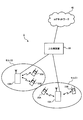
- FIG. 1 is a diagram illustrating an example of Hetnet to which MU-MIMO transmission is applied.
- the system shown in FIG. 1 has a hierarchical configuration in which a small base station (for example, RRH: Remote Radio Head, etc.) having a local coverage area is provided in the coverage area of a radio base station (for example, eNB: eNodeB).
- a radio base station for example, eNB: eNodeB
- UE User Equipment
- # 2 data for a plurality of user terminals UE # 1 and # 2 are simultaneously transmitted from a plurality of antennas of a radio base station.
- data for a plurality of user terminals UE # 3 and # 4 are simultaneously transmitted from a plurality of antennas of a plurality of small base stations.
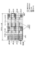
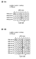
- FIG. 2 is a diagram illustrating an example of a radio frame (for example, one subframe) to which downlink MU-MIMO transmission is applied.
- radio resources for a downlink control channel (PDCCH: Physical Downlink Control Channel) from the beginning to a predetermined OFDM symbol (maximum 3 OFDM symbols) in each subframe. It is secured as a region (PDCCH region).
- PDSCH area for a downlink shared data channel (PDSCH: Physical Downlink Shared Channel) is secured in radio resources after a predetermined symbol from the top of the subframe.
- Downlink control information for user terminals UE (here, UE # 1 to # 4) is allocated to the PDCCH region.
- DCI includes data allocation information for the user terminal UE in the PDSCH region.
- the user terminal UE # 2 receives data for the user terminal UE # 2 assigned to the PDSCH region based on the DCI for the user terminal UE # 2 assigned to the PDCCH region.
- DCI allocation areas cannot be secured for all user terminals UE # 1 to # 6 in the PDCCH area.
- DCI for user terminals UE # 5 and # 6 cannot be assigned.
- the effect of improving the use efficiency of radio resources by MU-MIMO transmission may not be obtained sufficiently.
- the PDCCH allocation region is expanded from the beginning of the subframe to a control region other than a maximum of 3 OFDM symbols (the PDCCH region is expanded to an existing PDSCH region after 4 OFDM symbols). Can be considered.
- a method for extending the PDCCH region as shown in FIG. 3A, a method of time-division multiplexing PDSCH and PDCCH in the existing PDSCH region (TDM approach), as shown in FIG. 3B, PDSCH and PDCCH in the existing PDSCH region. And frequency division multiplexing (FDM approach).
- PDCCHs are arranged over the entire system band in some OFDM symbols after 4 OFDM symbols in a subframe.
- PDCCH is arranged in a part of the system band in all OFDM symbols after 4 OFDM symbols in a subframe.
- the PDCCH frequency-division multiplexed with the PDSCH by this FDM approach can be demodulated using a demodulation reference signal (DM-RS: DeModulation-Reference Signal) which is a user-specific reference signal.
- DM-RS DeModulation-Reference Signal
- enhanced PDCCH enhanced PDCCH
- This enhanced PDCCH may be called an enhanced downlink control channel, ePDCCH, E-PDCCH, FDM type PDCCH, UE-PDCCH, or the like.
- FIG. 4 is a diagram illustrating an example of a DCI mapping method in the extended PDCCH.
- FIG. 4A shows an example of local mapping
- FIG. 4B shows an example of distributed mapping.
- the extended PDCCH resource is composed of a predetermined number of resource block pairs (PRB (Physical Resource Block) pairs, hereinafter referred to as “PRB pairs”) distributed in the system band.
- PRB pairs Physical Resource Block pairs
- the PRB pair is composed of two PRBs continuous in the time direction (first half slot and second half slot), and is identified by a PRB index given in the frequency direction.
- the plurality of PRB pairs constituting the extended PDCCH resource are determined by higher layers or specifications.
- the PRB index for identifying each of the plurality of PRB pairs is notified to the user terminal UE by higher layer signaling or the like.
- 1DCI is locally mapped to a specific PRB pair constituting the extended PDCCH resource. Specifically, 1DCI is mapped within 1 PRB pair (for example, PRB pair with the best channel quality) based on the CQI fed back from the user terminal UE. In local mapping, frequency scheduling gain can be obtained by using CQI.
- PDSCH may be mapped to a PRB pair to which DCI is not mapped among a plurality of PRB pairs constituting the extended PDCCH resource.
- 1DCI is distributed and mapped to a plurality of PRB pairs constituting the extended PDCCH resource.
- 1DCI is divided into a plurality of divided units, and each divided unit is distributed and mapped to the plurality of PRB pairs (may be all PRB pairs).
- frequency diversity gain can be obtained by dispersing 1DCI in the system band.
- each DCI is divided into a plurality of divided units, and each divided unit is distributed and mapped to a plurality of PRB pairs constituting the extended PDCCH resource.
- the downlink control information (DCI) allocated to the existing PDCCH arranged from the top of the subframe to the predetermined OFDM symbol is generated in units of control channel elements (CCE).
- the CCE is composed of nine resource element groups (REG: Resource Element Group), and each REG is composed of a set of four resource elements (RE: Resource Element).
- the present inventors are considering generating downlink control information (DCI) to be assigned to the extended PDCCH in units of predetermined control channel elements so that the existing CCE can be reused (for example, blind decoding).
- DCI downlink control information
- eCCE enhanced Channel Control Element
- the extended control channel element can be composed of a plurality of resource element groups, and distributedly mapped in units of resource elements to a plurality of PRB pairs for extended PDCCH.
- a resource element group constituting an extended control channel element eCCE
- eREG enhanced Resource Element Group
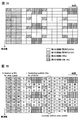
- FIG. 5 is a diagram illustrating an example of distributed mapping when an extended PDCCH is provided.
- a system band is composed of 11 physical resource blocks (PRB pairs).
- the 11 PRB pairs are assigned PRB indexes (PRB # 0 to # 10) along the frequency direction.
- the extended PDCCH is set to four PRB pairs # 1, # 4, # 8, and # 10 (see FIG. 5A).
- the extended PDCCH is mapped in units of PRBs, but is not limited to this. For example, it may be performed in units of resource block groups (RBGs) composed of a plurality of continuous PRBs (for example, two or four PRB pairs).
- RBGs resource block groups
- each PRB pair is composed of 4 eCCEs
- the total number of eCCEs is 16.
- different eCCE index numbers # 0 to # 15 are assigned to each eCCE (see FIG. 5B).
- Each eCCE is mapped to a PRB pair (see FIG. 5C) and then transmitted to the user terminal.
- each eCCE is distributed to a plurality of PRB pairs (for example, PRB pairs # 1, # 4, # 8, and # 10).
- the mapping can be performed in units of division units (eREG) (see FIG. 5C).
- FIG. 5C shows a case where eCCE with index number 0 (eCCE # 0) is mapped to eREG (eREG # 0) with index number 0 of PRB # 1 and eREG # 4 with PRB # 8. That is, the two eREGs constituting the eCCE # 0 are mapped as eREG # 0 of PRB # 1 and eREG # 4 of PRB # 8.
- an eREG which is a mapping unit of eCCE for a PRB pair, with a predetermined number of resource elements (RE).
- RE resource elements
- the number of REs that can be used as extended PDCCH is defined as a predetermined value (for example, 144), and the number of REs of the predetermined value Based on this, the number of eREG divisions (the number of eREGs included in one PRB pair) can be determined.
- the 144 corresponds to the total number of REs in one PRB pair (168) minus the number of REs in which DM-RSs are arranged (24). To do.
- FIG. 6 when one PRB pair is divided into eight eREGs (eREG # 0 to # 7), a method of providing eREG by dividing the PRB pair in a predetermined frequency / time axis direction is considered. It is done.
- the eREG when one PRB pair is divided into eight eREGs (eREG # 0 to # 7), the eREG is provided by dividing into four in the frequency axis direction and dividing into two in the time axis direction (first half slot and second half slot). Shows the case.
- 1PRB is composed of 4 eCCEs (eg, 1eCCE is 36 REs)
- 1eCCE can be composed of 2 eREGs. That is, FIG. 6 shows a case where 1 eCCE composed of two eREGs is mapped to a PRB pair in units of eREG.
- each eREG when each eREG is provided in an area partitioned in the frequency axis direction and the time axis direction in one PRB pair, REs constituting the 1 eREG are collectively arranged in a predetermined area. That is, as shown in FIG. 6, the eREGs to which the respective index numbers are attached are provided collectively in areas divided in the frequency and time axis directions.
- the number of REs that can be used for the extended PDCCH is different (non-uniform) between eREGs assigned different index numbers.
- the RE in the region where the DM-RS is arranged in one PRB pair cannot be used for the extended PDCCH.
- eREG # 3 includes 17 REs
- eREG # 5 includes 19 REs. Therefore, depending on the combination of a plurality of eREGs, the sizes may be different (non-uniform) among the plurality of eCCEs.
- each eREG is aggregated and provided in a predetermined area within one PRB pair, a large number of REs constituting the 1eREG are arranged in the same OFDM symbol.
- the total power is limited within one OFDM symbol, if the eREGs are aggregated in a predetermined area, there is a possibility that the power utilization efficiency cannot be sufficiently achieved without averaging between the eREGs.
- the present inventors have mapped a plurality of REs constituting each eREG and / or a plurality of eREGs constituting each eCCE in a resource region (PRB, RBG, etc.) where the extended PDCCH is located. It has been found that downlink control information can be appropriately allocated to the resource region for the extended PDCCH by controlling the method.
- the present inventors have found that power utilization efficiency can be improved by distributing a plurality of REs constituting 1eREG into a plurality of OFDM symbols in a resource region where the extended PDCCH is arranged. Also, at least in the existing LTE system (Rel. 8 to Rel10), a region where a control channel (existing PDCCH arranged in 1 to 3 OFDM symbols from the top of a subframe) is arranged, a reference signal (for example, CRS (Cell specific) Reference REGISTER (Signal Signal)) and RE in the area where the data channel (existing PDSCH) is located are allocated uniformly to the REs constituting the eREG of each index number.
- CRS Cell specific
- Reference REGISTER Signal
- a plurality of eREGs constituting 1 eCCE are distributed to a plurality of resource regions where extended PDCCHs are arranged, and downlink control information (DCI) is mapped so that index numbers of the plurality of eREGs constituting 1 eCCE are different from each other.
- DCI downlink control information
- EREG index assignment method With reference to FIG. 7, a method of assigning an eREG index to each RE (arrangement pattern control of a plurality of REs constituting each eREG) in a resource region where the ePDCCH is arranged will be described.
- the resource area is described by taking, as an example, a 1PRB pair in a normal cyclic prefix / normal subframe, but is not limited thereto.
- FIG. 7A shows a resource region (1PRB) in which ePDCCH is arranged.
- the resource region shown in FIG. 7 includes first to third regions that can be used for ePDCCH, and a fourth region in which DM-RSs are arranged and not used for ePDCCH.
- the first region, the second region, and the third region are each arranged in the existing LTE system (or another resource region in which ePDCCH is not arranged) in PDSCH and 1 to 3 OFDM symbols from the top of the subframe. This corresponds to an area where the existing PDCCH and the reference signal (CRS) are arranged.
- CRS reference signal
- the reference signal (CRS) is arranged in the resource area where the ePDCCH is arranged
- the first area and the second area are used for the ePDCCH and the reference signal and the existing PDCCH are arranged
- the first area is used for ePDCCH. That is, in the resource region, the first region is the region most likely to be used for eCCE mapping.
- mapping is performed so that the number of REs constituting different eREGs is uniform and a plurality of REs constituting one eREG are distributed over a plurality of OFDM symbols.
- the uniform number of REs constituting different eREGs is not necessarily limited to the case where the number of REs is the same between different eREGs, and the difference in the number of REs between eREGs is made as small as possible (preferably different eREGs). The difference in the number of REs that constitute each is set to be within 1).
- the REs in the regions (first region to third region) that can be used for ePDCCH are numbered (numbered) in order from the REs that are likely to be used for ePDCCH (see FIG. 7B).
- the regions (second region and third region) that may be used for other signals are numbered.
- FIG. 7B shows a case where the numbering is performed on the second area and then the numbering is performed on the third area, the numbering may be performed in the reverse order. Further, the numbering is not performed for the RE in the fourth area where the DM-RS is arranged.
- numbering is performed in order along the frequency axis direction (vertical direction in FIG. 7B), starting from the RE in the region having the smallest frequency and time in the first region.
- a cyclic shift may be applied to each OFDM symbol as shown in FIG. 7B so that the REs constituting each eREG are dispersed as much as possible.
- REs in the first area are numbered from 0 to 95.
- the REs in the second region are numbered from 96 to 127 along one OFDM symbol from the 3OFDM symbol side, and then the REs in the third region are numbered from 128 to 143. .
- Step 2 a modulo operation is applied to the index assigned to each RE in step 1 using the number N of eREGs provided in the PRB pair. This case corresponds to the case where the PRB pair is divided into N eREGs.
- the number N of eREGs provided in the PRB pair can be selected from 8, 12, 16, 24, or 36, for example. This is because by selecting one of these numbers, the number of REs (144) that can be used for ePDCCH can be evenly allocated to each eREG. In particular, N is preferably 8, 16, or 36.
- an index (eREG index number) of 0 to 7 is attached to an RE that can be used as ePDCCH.
- the eight eREGs with index numbers 0 to 7 are each composed of a maximum of 18 REs.
- an index (eREG index number) of 0 to 15 is attached to an RE that can be used as ePDCCH.
- the 16 eREGs with index numbers 0 to 15 are each composed of a maximum of 9 REs.
- the RE number corresponding to each RE is determined by modulo calculation, thereby distributing a plurality of REs constituting one eREG into a plurality of OFDM symbols. It becomes possible. As a result, a large number of REs of eREGs having different index numbers can be arranged in the same OFDM symbol, and the power can be equalized between the OFDM symbols. Therefore, compared with the eREG allocation shown in FIG. The utilization efficiency of can be improved.
- an index number is assigned to each region.
- REs of different eREGs can be equally arranged. As a result, even when a reference signal (CRS) and / or an existing PDCCH is arranged in a resource area allocated for ePDCCH, the sizes of the respective eREGs can be made substantially uniform.
- eCCE mapping method using eREG as an allocation unit Next, an eCCE mapping method for a plurality of resource areas will be described.
- a plurality of eREGs constituting 1 eCCE are distributed to a plurality of resource areas (here, PRB pairs) in which extended PDCCHs are arranged, and the index numbers of each eREG distributed to each resource area
- the downlink control information (DCI) is mapped so that each is different.
- DCI downlink control information
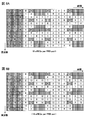
- an example of a method for mapping eCCEs in units of eREGs to a plurality of resource regions (here, PRB pairs) that can be used as ePDCCH will be described with reference to FIG.
- a case where 36 REs constituting an eCCE are defined 36 RE / 1 eCCE
- the size of the eCCE is not limited to this.
- the total number of eCCEs that can be used for downlink control information (DCI) transmitted using ePDCCH in the system band is the resource area ⁇ 4 arranged as ePDCCH.
- DCI downlink control information
- the number of eREGs constituting 1 eCCE can be obtained by “36 / (144 / N)”. That is, the value is obtained by dividing the number 36 of REs constituting 1 eCCE by the size of eREG (number of REs constituting 1 eREG). As described above, N corresponds to the number of eREGs provided in one resource region (for example, one PRB pair).
- the number of eREGs constituting one eCCE is two.
- the number of eREGs constituting one eCCE is 4.
- FIG. 9A shows four resource areas in which extended PDCCHs are arranged (here, PRB pairs # 1 to # 4), and each PRB pair and a plurality of eREGs when the number N of eREGs allocated to one PRB pair is 16.
- the relationship with (eREG index) is shown. That is, eREGs # 0 to # 15 are mapped to the PRB pairs # 1 to # 4.
- the REs constituting each of the eREGs # 0 to # 15 can be distributed and arranged in each PRB pair.
- the number of eCCEs allocated to one PRB pair is 4, the number of eREGs constituting one eCCE is 4.
- a plurality of eCCEs (here, 16 eCCEs # 0 to # 15) can be mapped to each PRB # 1 to # 4 as shown in FIG. 9B.
- mapping is performed so that a plurality of eREGs constituting one eCCE are distributed to different PRB pairs and the index numbers of the plurality of eREGs distributed to different PRB pairs are different. That is, a plurality of eREGs constituting one eCCE are mapped to different PRB pairs with different eREG index numbers attached thereto.
- a frequency diversity effect can be obtained by mapping a plurality of eREGs constituting one eCCE to different PRB pairs.
- 1 eCCE by configuring 1 eCCE with eREGs having different index numbers, it is possible to reduce non-uniform sizes between eCCEs.
- the eCCE index is mapped in order to the eREG index of a plurality of PRB pairs.
- mapping is performed so that eCCEs having consecutive index numbers are assigned to different PRB pairs. For example, as shown in FIG. 9B, eCCEs # 0 to # 3 are allocated to eREG # 0 allocated to PRB pairs # 1 to # 4. Similarly, eCCEs # 4 to # 7 are assigned to eREG # 1 assigned to PRB pairs # 1 to # 4. The same procedure is performed until a plurality of eCCEs complete a cycle. As a result, eCCEs # 0 to # 15 are assigned to eREGs # 0 to # 3 assigned to the PRB pairs # 1 to # 4.
- a cyclic shift is added and assigned in the same manner. For example, as shown in FIG. 9B, eCCEs # 0 to # 3 are allocated to eREG # 4 allocated to PRB pairs # 1 to # 4. However, in each eREG index, each eCCE is assigned in the order of PRB pairs # 2 to # 3, # 4, and # 1 (cyclic shift).
- a plurality of eCCEs can be mapped to each PRB pair in units of eREGs as shown in FIG. 9B.
- four eREGs constituting eCCE # 0 having an eCCE index number of 0 are distributed and allocated to PRBs # 1 to # 4, respectively.
- the four eREGs that make up eCCE # 0 are eREG # 0 (PRB pair # 1), eREG # 4 (PRB pair # 2), eREG # 8 (PRB pair # 3), eREG # 12 (PRB pair). # 4).
- mapping a plurality of eREGs constituting one eCCE to different PRB pairs with different eREG index numbers attached thereto it is possible to obtain a frequency diversity effect and to make the sizes of the eCCEs uniform.
- eREGs mapped to each PRB pair can be distributed and arranged in REs of a plurality of OFDM symbols in one PRB as shown in FIG. As a result, it is possible to improve the power utilization efficiency and to effectively equalize the size between eREGs and between eCCEs.
- a plurality of eREGs constituting one eCCE are mapped to different PRB pairs with different eREG index numbers.
- the total number of eCCEs (16 in FIG. 10A and 32 in FIG. 10B) is larger than the number of eREGs included in one PRB pair.
- the eCCE index is sequentially mapped to the eREG indexes of a plurality of PRB pairs, and as a result, eREGs of eCCEs having consecutive index numbers are assigned to different PRB pairs. .
- eREGs constituting eCCE # 0 and eCCE # 1 are mapped to different PRB pairs.
- two eREGs constituting eCCE # 0 are mapped to PRB pair # 1 (eREG # 0) and PRB pair # 3 (eREG # 4), and two eREGs constituting eCCE # 1 are mapped.
- eREG is mapped to PRB pair # 2 (eREG # 0) and PRB pair # 4 (eREG # 4).
- each frequency resource unit constituting the extended PDCCH set is described as being a PRB pair.
- Each frequency resource unit may be a PRB, or an RBG (Resource Block Group) composed of PRBs continuous in the frequency direction.
- FIG. 11 is an explanatory diagram of a system configuration of the wireless communication system according to the present embodiment.
- the radio communication system shown in FIG. 11 is a system including, for example, an LTE system or a successor system.
- carrier aggregation in which a plurality of fundamental frequency blocks with the system band of the LTE system as a unit is integrated is used.
- this wireless communication system may be called IMT-Advanced or 4G.
- the radio communication system 1 includes a radio base station 10 and a plurality of user terminals 20 that communicate with the radio base station 10.
- the radio base station 10 is connected to the upper station apparatus 30, and the upper station apparatus 30 is connected to the core network 40.
- the wireless base stations 10 are connected to each other by wired connection or wireless connection.
- Each user terminal 20 (20A, 20B) can communicate with the radio base station 10 in the cells C1, C2.
- the upper station device 30 includes, for example, an access gateway device, a radio network controller (RNC), a mobility management entity (MME), and the like, but is not limited thereto.
- RNC radio network controller
- MME mobility management entity
- Each user terminal 20 includes an LTE terminal and an LTE-A terminal.
- the user terminal 20 will be described as a user terminal unless otherwise specified.
- OFDMA Orthogonal Frequency Division Multiple Access
- SC-FDMA Single Carrier-Frequency Division Multiple Access
- the wireless access method is not limited to this.
- OFDMA is a multi-carrier transmission scheme that performs communication by dividing a frequency band into a plurality of narrow frequency bands (subcarriers) and mapping data to each subcarrier.
- SC-FDMA is a single carrier transmission method that reduces interference between terminals by dividing a system band into bands each consisting of one or continuous resource blocks for each terminal, and a plurality of terminals using different bands. .
- the downlink communication channel includes PDSCH (Physical Downlink Shared Channel) as a downlink data channel shared by each user terminal 20, a downlink L1 / L2 control channel (PDCCH, PCFICH, PHICH), and an extended PDCCH obtained by extending PDCCH. And have.
- PDSCH Physical Downlink Shared Channel
- PDSCH and PUSCH scheduling information and the like are transmitted by PDCCH (Physical Downlink Control Channel).
- the number of OFDM symbols used for PDCCH is transmitted by PCFICH (Physical Control Format Indicator Channel).
- the HARQ ACK / NACK for PUSCH is transmitted by PHICH (Physical Hybrid-ARQ Indicator Channel).
- the extended PDCCH is used to support a lack of PDCCH capacity using a resource region to which the PDSCH is allocated.
- the uplink communication channel has PUSCH (Physical Uplink Shared Channel) as an uplink data channel shared by each user terminal and PUCCH (Physical Uplink Control Channel) as an uplink control channel. User data and higher control information are transmitted by this PUSCH. Also, downlink radio quality information (CQI: Channel Quality Indicator), ACK / NACK, and the like are transmitted by PUCCH.
- PUSCH Physical Uplink Shared Channel
- PUCCH Physical Uplink Control Channel
- FIG. 12 is an overall configuration diagram of the radio base station 10 according to the present embodiment.
- the radio base station 10 includes a plurality of transmission / reception antennas 101 for MIMO transmission, an amplifier unit 102, a transmission / reception unit 103, a baseband signal processing unit 104, a call processing unit 105, and a transmission path interface 106. Yes.
- User data transmitted from the radio base station 10 to the user terminal 20 via the downlink is input from the higher station apparatus 30 to the baseband signal processing unit 104 via the transmission path interface 106.
- the baseband signal processing unit 104 performs PDCP layer processing, user data division / combination, RLC layer transmission processing such as RLC (Radio Link Control) retransmission control transmission processing, MAC (Medium Access Control) retransmission control, for example, HARQ transmission processing, scheduling, transmission format selection, channel coding, Inverse Fast Fourier Transform (IFFT) processing, and precoding processing are performed and transferred to each transceiver 203.
- RLC layer transmission processing such as RLC (Radio Link Control) retransmission control transmission processing, MAC (Medium Access Control) retransmission control, for example, HARQ transmission processing, scheduling, transmission format selection, channel coding, Inverse Fast Fourier Transform (IFFT) processing, and precoding processing are performed and transferred to each transceiver 203.
- RLC layer transmission processing such as RLC (Radio Link Control) retransmission control transmission processing, MAC (Medium Access Control) retransmission control, for example, HARQ transmission processing, scheduling, transmission format selection, channel coding, Inverse
- the baseband signal processing unit 104 notifies the control information for communication in the cell to the user terminal 20 through the broadcast channel.
- the information for communication in the cell includes, for example, the system bandwidth in the uplink or the downlink.
- Each transmission / reception unit 103 converts the baseband signal output by precoding from the baseband signal processing unit 104 for each antenna to a radio frequency band.
- the amplifier unit 102 amplifies the frequency-converted radio frequency signal and transmits the amplified signal using the transmission / reception antenna 101.
- radio frequency signals received by the respective transmission / reception antennas 101 are amplified by the amplifier units 102 and frequency-converted by the respective transmission / reception units 103. It is converted into a baseband signal and input to the baseband signal processing unit 104.
- the baseband signal processing unit 104 performs FFT processing, IDFT processing, error correction decoding, MAC retransmission control reception processing, RLC layer, and PDCP layer reception processing on user data included in the input baseband signal.
- the data is transferred to the higher station apparatus 30 via the transmission path interface 106.
- the call processing unit 105 performs call processing such as communication channel setting and release, status management of the radio base station 10, and radio resource management.
- FIG. 13 is an overall configuration diagram of the user terminal 20 according to the present embodiment.
- the user terminal 20 includes a plurality of transmission / reception antennas 201 for MIMO transmission, an amplifier unit 202, a transmission / reception unit (reception unit) 203, a baseband signal processing unit 204, and an application unit 205.
- radio frequency signals received by a plurality of transmission / reception antennas 201 are each amplified by an amplifier unit 202, converted in frequency by a transmission / reception unit 203, and converted into a baseband signal.
- the baseband signal is subjected to FFT processing, error correction decoding, retransmission control reception processing, and the like by the baseband signal processing unit 204.
- downlink user data is transferred to the application unit 205.
- the application unit 205 performs processing related to layers higher than the physical layer and the MAC layer. Also, broadcast information in the downlink data is also transferred to the application unit 205.
- uplink user data is input from the application unit 205 to the baseband signal processing unit 204.
- transmission processing for retransmission control H-ARQ (Hybrid ARQ)
- channel coding precoding
- DFT processing IFFT processing
- the like are performed and transferred to each transmission / reception unit 203.
- the transmission / reception unit 203 converts the baseband signal output from the baseband signal processing unit 204 into a radio frequency band.
- the amplifier unit 202 amplifies the frequency-converted radio frequency signal and transmits the amplified signal using the transmission / reception antenna 201.
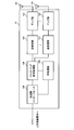
- FIG. 14 is a functional configuration diagram of the baseband signal processing unit 104 and some upper layers included in the radio base station 10 according to the present embodiment. Although FIG. 14 mainly shows a functional configuration for downlink (transmission), the radio base station 10 may include a functional configuration for uplink (reception).
- the radio base station 10 includes an upper layer control information generation unit 300, a data generation unit 301, a channel encoding unit 302, a modulation unit 303, a mapping unit 304, a downlink control information generation unit 305, common control information.
- the higher layer control information generation unit 300 generates higher layer control information for each user terminal 20.
- the upper layer control information is control information that is subjected to upper layer signaling (for example, RRC signaling), and includes, for example, extended PDCCH set allocation information (described later).
- the data generation unit 301 generates downlink user data for each user terminal 20.
- the downlink user data generated by the data generation unit 301 and the upper layer control information generated by the upper layer control information generation unit 300 are input to the channel encoding unit 302 as downlink data transmitted by the PDSCH.
- the channel coding unit 302 performs channel coding on the downlink data for each user terminal 20 according to a coding rate determined based on feedback information from each user terminal 20.
- the modulation unit 303 modulates the channel-coded downlink data according to a modulation scheme determined based on feedback information from each user terminal 20.
- the mapping unit 304 maps the modulated downlink data according to the instruction from the scheduling unit 317.
- the downlink control information generation unit 305 generates UE-specific downlink control information (DCI) for each user terminal 20.
- UE-specific downlink control information includes PDSCH allocation information (DL assignment), PUSCH allocation information (UL grant), and the like.
- the common control information generation unit 306 generates cell-specific common control information.
- the downlink control information generated by the downlink control information generation unit 305 and the common control information generated by the common control information generation unit 306 are input to the channel coding unit 307 as downlink control information transmitted on the PDCCH or the extended PDCCH.
- the Downlink control information transmitted in PDCC can be generated in units of control channel elements (CCE), and downlink control information transmitted in extended PDCCH can be generated in units of extended control channel elements (eCCE). Note that the CCE and eCCE sizes (number of REs) may be different or the same.
- the channel coding unit 307 channel-codes the input downlink control information according to the coding rate instructed from the scheduling unit 317.
- Modulation section 308 modulates the channel-coded downlink control information according to the modulation scheme instructed from scheduling section 317.
- downlink control information transmitted on the PDCCH is input from the modulation unit 308 to the control channel multiplexing unit 309 and multiplexed.
- the downlink control information multiplexed by the control channel multiplexing unit 309 is interleaved by the interleaving unit 310.
- the interleaved downlink control information is input to the IFFT unit 312 together with the measurement reference signal (CSI-RS: Channel State Information-Reference Signal, CRS: Cell specific Reference Signal, etc.) generated by the measurement reference signal generation unit 311. Is done.
- CSI-RS Channel State Information-Reference Signal
- CRS Cell specific Reference Signal, etc.
- mapping unit 313 maps the downlink control information in a predetermined allocation unit (for example, eREG unit) according to the instruction from the scheduling unit 317.
- the mapping unit 313 performs distributed mapping on the eCCE to which downlink control information is allocated for each resource region set for the extended PDCCH.
- the mapping unit 313 can also switch between distributed mapping and local mapping (Localized Mapping).
- the mapping unit 313 distributes a plurality of eREGs constituting one eCCE to a plurality of resource regions (PRB pairs or RBGs) in which extended PDCCHs are arranged, and to each resource region. Mapping is performed so that the index numbers of the eREGs differ. For example, as shown in FIG. 9, a plurality of eREGs constituting one eCCE are assigned different eREG index numbers and mapped to different PRB pairs, thereby obtaining a frequency diversity effect and the size of the eCCEs. Uniformity can be achieved.
- the mapping unit 313 can disperse and arrange eREGs mapped to each PRB pair in the REs of a plurality of OFDM symbols in one PRB. As a result, it is possible to improve the power utilization efficiency and to effectively equalize the size between eREGs and between eCCEs.
- the position (resource area) where the eREGs constituting each eCCE are mapped, the index number of the eREGs constituting each eCCE, the RE pattern corresponding to each eREG in the resource area, and the like are based on information from the scheduling unit 317. It may be set or determined in advance according to the specification.
- the mapped downlink control information includes downlink data transmitted on the PDSCH (that is, downlink data mapped by the mapping unit 304), and a demodulation reference signal (DM-RS) generated by the demodulation reference signal generation unit 314. At the same time, it is input to the weight multiplier 315.
- Weight multiplying section 315 multiplies downlink data transmitted by PDCSH, downlink control information transmitted by enhanced PDCCH, and a demodulation reference signal by a precoding weight specific to user terminal 20, and performs precoding.
- the precoded transmission data is input to the IFFT unit 312 and converted from a frequency domain signal to a time-series signal by inverse fast Fourier transform.
- a cyclic prefix (CP) functioning as a guard interval is inserted by the CP insertion unit 316 into the output signal from the IFFT unit 312 and output to the transmission / reception unit 103.
- the scheduling unit 317 schedules downlink data transmitted on the PDSCH, downlink control information transmitted on the enhanced PDCCH, and downlink control information transmitted on the PDCCH.
- the scheduling unit 317 includes CSI (Channel State Information) including instruction information from the upper station device 30 and feedback information from each user terminal 20 (for example, CQI (Channel Quality Indicator), RI (Rank Indicator), etc.). ) Etc.), radio resources are allocated.
- CSI Channel State Information
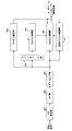
- FIG. 15 is a functional configuration diagram of the baseband signal processing unit 204 included in the user terminal 20.
- 15 mainly shows a functional configuration for downlink (reception), but the user terminal 20 may have a functional configuration for uplink (transmission).
- the user terminal 20 includes a CP removing unit 401, an FFT unit 402, a demapping unit 403, a deinterleaving unit 404, a PDCCH demodulating unit 405, a PDSCH demodulating unit 406, an extended PDCCH demodulating unit 407, a channel estimating unit, as a functional configuration for downlink. 408.
- the cyclic prefix (CP) is removed from the downlink signal received as reception data from the radio base station 10 by the CP removal unit 401.
- the downlink signal from which the CP is removed is input to the FFT unit 402.
- the FFT unit 402 performs fast Fourier transform (FFT) on the downlink signal to convert the signal in the time domain to the signal in the frequency domain, and inputs the signal to the demapping unit 403.
- the demapping unit 403 demaps the downlink signal. Note that the demapping process by the demapping unit 403 is performed based on higher layer control information input from the application unit 205.
- the downlink control information output from the demapping unit 403 is deinterleaved by the deinterleaving unit 404.
- the PDCCH demodulation unit 405 performs blind decoding, demodulation, channel decoding, and the like of downlink control information (DCI) output from the deinterleaving unit 404 based on the channel estimation result by the channel estimation unit 408. Specifically, PDCCH demodulation section 405 performs blind decoding on a search space candidate notified in advance from radio base station 10 or a predetermined search space candidate, and acquires downlink control information.
- DCI downlink control information
- the PDSCH demodulation unit 406 performs demodulation, channel decoding, and the like of the downlink data output from the demapping unit 403 based on the channel estimation result by the channel estimation unit 408. Specifically, the PDSCH demodulator 406 receives the PDSCH assigned to the terminal based on the downlink control information demodulated by the PDCCH demodulator 405 or the extended PDCCH demodulator 407 (for example, downlink scheduling information such as DL grant). Demodulate and acquire downlink data (downlink user data and higher layer control information) addressed to the terminal itself.
- the extended PDCCH demodulation unit 407 performs blind decoding, demodulation, channel decoding, and the like of the extended PDCCH demodulation unit 407 output from the demapping unit 403 based on the channel estimation result by the channel estimation unit 408.
- the channel estimation unit 408 performs channel estimation using a demodulation reference signal (DM-RS), a measurement reference signal (CRS, CSI-RS), and the like.
- Channel estimation section 408 outputs a channel estimation result based on measurement reference signals (CRS, CSI-RS) to PDCCH demodulation section 405.
- channel estimation section 408 outputs the channel estimation result based on the demodulation reference signal (DM-RS) to PDSCH demodulation section 406 and enhanced PDCCH demodulation section 407.
- a beamforming gain can be obtained for the PDSCH and the extended PDCCH by demodulation using a demodulation reference signal (DM-RS) unique to the user terminal 20.
- DM-RS demodulation reference signal
- the radio base station 10 generates downlink control information for each extended control channel element (eCCE) and is arranged for the extended downlink control channel. Downlink control information is mapped to a plurality of resource areas in units of eREG.
- the radio base station 10 distributes a plurality of eREGs constituting one eCCE in a plurality of resource areas, and performs mapping so that the index numbers of the eREGs distributed in the resource areas are different.
- the radio base station 10 arranges eREGs mapped to each PRB pair in a distributed manner in REs of a plurality of OFDM symbols in one PRB. As a result, it is possible to improve the frequency diversity effect and the power utilization efficiency, and to effectively equalize the size between eREGs and between eCCEs.
Landscapes
- Engineering & Computer Science (AREA)
- Signal Processing (AREA)
- Computer Networks & Wireless Communication (AREA)
- Mobile Radio Communication Systems (AREA)
Abstract
拡張された下り制御チャネルにおいて下り制御情報に無線リソースを適切に割り当てること。無線基地局が下り共有データチャネルと周波数分割多重される拡張下り制御チャネルを介して各ユーザ端末に対する下り制御情報を送信する無線通信システムにおける無線通信方法であって、無線基地局は、複数のeREGで構成されるeCCE単位で下り制御情報を生成する工程と、拡張下り制御チャネル用の複数のリソース領域に、下り制御情報をeREG単位でマッピングする工程とを有し、eREGは複数のREで構成されており、無線基地局は、各リソース領域において、異なる拡張リソース要素グループ(eREG)をそれぞれ構成するリソース要素(RE)数が均一となり、且つ1eREGを構成する複数のREを複数のOFDMシンボルに分散するようにマッピングを行う。
Description
本発明は、次世代無線通信システムにおける無線通信方法、無線通信システム及び無線基地局に関する。
UMTS(Universal Mobile Telecommunications System)ネットワークにおいて、更なる高速データレート、低遅延などを目的としてロングタームエボリューション(LTE:Long Term Evolution)が検討されている(非特許文献1)。LTEではマルチアクセス方式として、下り回線(下りリンク)にOFDMA(Orthogonal Frequency Division Multiple Access)をベースとした方式を用い、上り回線(上りリンク)にSC-FDMA(Single Carrier Frequency Division Multiple Access)をベースとした方式を用いている。
また、LTEからのさらなる広帯域化及び高速化を目的として、LTEの後継システム(例えば、LTEアドバンスト又はLTEエンハンスメントと呼ぶこともある(以下、「LTE-A」という))も検討されている。LTE(Rel.8)やLTE-A(Rel.9、Rel.10)においては、複数のアンテナでデータを送受信し、周波数利用効率を向上させる無線通信技術としてMIMO(Multi Input Multi Output)技術が検討されている。MIMO技術においては、送受信機に複数の送信/受信アンテナを用意し、異なる送信アンテナから同時に異なる送信情報系列を送信する。
3GPP TR 25.913"Requirements for Evolved UTRA and Evolved UTRAN"
ところで、LTEの後継システムとなるLTE-Aでは、異なる送信アンテナから同時に異なるユーザに送信情報系列を送信するマルチユーザMIMO(MU-MIMO:Multiple User MIMO)伝送が検討されている。このMU-MIMO伝送は、Hetnet(Heterogeneous network)やCoMP(Coordinated Multi-Point)伝送にも適用される。
将来のシステムでは、無線基地局に接続されるユーザ数が増加することにより、下り制御情報を伝送する下り制御チャネルの容量が不足することが想定される。このため、従来の無線リソースの割当て方法ではMU-MIMO伝送等の将来のシステムの特性を十分に発揮できないおそれがある。
このような問題を解決する決法として、下り制御チャネル用の無線リソース領域を拡張して、より多くの下り制御情報を伝送する方法が考えられる。かかる場合、拡張された下り制御チャネルにおいて、下り制御情報に対してどのように無線リソースを割り当てるか、つまり、拡張制御チャネル用のリソース領域に対してどのように下り制御情報をマッピングするかが問題となる。
本発明はかかる点に鑑みてなされたものであり、拡張された下り制御チャネルにおいて下り制御情報に無線リソースを適切に割り当て可能な無線通信方法、無線通信システム及び無線基地局を提供することを目的とする。
本発明の無線通信方法は、無線基地局が下り共有データチャネルと周波数分割多重される拡張下り制御チャネルを介して各ユーザ端末に対する下り制御情報を送信する無線通信システムにおける無線通信方法であって、前記無線基地局は、複数の拡張リソース要素グループ(eREG)で構成される拡張制御チャネル要素(eCCE)単位で前記下り制御情報を生成する工程と、前記拡張下り制御チャネル用の複数のリソース領域に、前記下り制御情報を拡張リソース要素グループ(eREG)単位でマッピングする工程と、を有し、前記拡張リソース要素グループ(eREG)は複数のリソース要素(RE)で構成されており、前記無線基地局は、前記各リソース領域において、異なる拡張リソース要素グループ(eREG)をそれぞれ構成するリソース要素(RE)数が均一となり、且つ拡張リソース要素グループ(1eREG)を構成する複数のリソース要素(RE)が複数のOFDMシンボルに分散するようにマッピングを行うことを特徴とする。
本発明によれば、拡張された下り制御チャネルにおいて下り制御情報に無線リソースを適切に割り当てることができる。
図1は、MU-MIMO伝送が適用されるHetnetの一例を示す図である。図1に示すシステムは、無線基地局(例えば、eNB:eNodeB)のカバレッジエリア内に局所的なカバレッジエリアを有する小型基地局(例えば、RRH:Remote Radio Head等)が設けられ、階層的に構成されている。このようなシステムにおける下りリンクのMU-MIMO伝送では、無線基地局の複数のアンテナから複数のユーザ端末UE(User Equipment)#1及び#2に対するデータが同時に送信される。また、複数の小型基地局の複数のアンテナから複数のユーザ端末UE#3、#4に対するデータも同時に送信される。
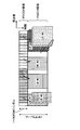
図2は、下りリンクのMU-MIMO伝送が適用される無線フレーム(例えば、1サブフレーム)の一例を示す図である。図2に示すように、MU-MIMO伝送が適用されるシステムでは、各サブフレームにおいて先頭から所定のOFDMシンボル(最大3OFDMシンボル)まで、下り制御チャネル(PDCCH:Physical Downlink Control Channel)用の無線リソース領域(PDCCH領域)として確保される。また、サブフレームの先頭から所定のシンボルより後の無線リソースに、下り共有データチャネル(PDSCH:Physical Downlink Shared Channel)用の無線リソース領域(PDSCH領域)が確保される。
PDCCH領域には、ユーザ端末UE(ここでは、UE#1~#4)に対する下り制御情報(DCI:Downlink Control Information)が割当てられる。DCIには、PDSCH領域におけるユーザ端末UEに対するデータの割り当て情報等が含まれる。例えば、図2において、ユーザ端末UE#2は、PDCCH領域に割り当てられたユーザ端末UE#2に対するDCIに基づいて、PDSCH領域に割り当てられたユーザ端末UE#2に対するデータを受信する。
また、MU-MIMO伝送においては、同一時間及び同一周波数で複数のユーザ端末UEに対するデータ送信が可能となる。このため、図2のPDSCH領域において、ユーザ端末UE#1に対するデータとユーザ端末UE#5に対するデータを同一の周波数領域に多重することが考えられる。同様に、ユーザ端末UE#4に対するデータとユーザ端末UE#6に対するデータを同一の周波数領域に多重することも考えられる。
しかしながら、図2に示すように、PDSCH領域においてユーザ端末UE#1~#6に対するデータを割り当てようとしても、PDCCH領域において全てのユーザ端末UE#1~#6に対するDCIの割り当て領域を確保できない場合がある。例えば、図2のPDCCH領域では、ユーザ端末UE#5及び#6に対するDCIを割り当てることができない。この場合、DCIを割り当てるPDCCH領域の不足によりPDSCH領域に多重されるユーザ端末UEの数が制限されるため、MU-MIMO伝送による無線リソースの利用効率の向上効果を十分に得られないおそれがある。
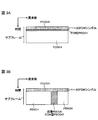
このようなPDCCH領域の不足を解決する方法として、サブフレームの先頭から最大3OFDMシンボルの制御領域以外にPDCCHの割当て領域を拡張する(4OFDMシンボル以降の既存のPDSCH領域にPDCCH領域を拡張する)ことが考えられる。PDCCH領域の拡張方法としては、図3Aに示すように、既存のPDSCH領域においてPDSCHとPDCCHとを時分割多重する方法(TDMアプローチ)、図3Bに示すように、既存のPDSCH領域においてPDSCHとPDCCHとを周波数分割多重する方法(FDMアプローチ)が考えられる。
図3Aに示すTDMアプローチでは、サブフレームの4OFDMシンボル以降の一部OFDMシンボルにおいてシステム帯域全体に渡りPDCCHが配置される。一方、図3Bに示すFDMアプローチでは、サブフレームの4OFDMシンボル以降の全OFDMシンボルにおいてシステム帯域の一部にPDCCHが配置される。このFDMアプローチによりPDSCHと周波数分割多重されるPDCCHは、ユーザ固有の参照信号である復調用参照信号(DM-RS:DeModulation-Reference Signal)を用いて復調することができる。このため、かかるPDCCHで伝送されるDCIは、PDSCHで伝送される下りデータと同様に、ビームフォーミングゲインを得ることができ、PDCCHのキャパシティの増大に有効である。今後は、このFDMアプローチが重要となると考えられる。
以下、FDMアプローチにおいてPDSCHと周波数分割多重されるPDCCHを拡張PDCCH(enhanced PDCCH)と称する。この拡張PDCCHは、拡張下り制御チャネル(enhanced physical downlink control channel)、ePDCCH、E-PDCCH、FDM型PDCCH、UE-PDCCH等と呼ばれてもよい。
以上のようなFDMアプローチの拡張PDCCHにおいて、DCIのマッピング方法として、本発明者らは局所マッピング(Localized mapping)と分散マッピング(Distributed Mapping)の適用を検討している。図4は、拡張PDCCHにおけるDCIのマッピング方法の一例を示す図である。図4Aは、局所マッピングの一例を示し、図4Bは、分散マッピングの一例を示している。
図4A及び4Bに示すように、拡張PDCCH用リソースは、システム帯域に分散された所定数のリソースブロックペア(PRB(Physical Resource Block)ペア、以下、「PRBペア」という)から構成される。PRBペアは、時間方向(前半スロット及び後半スロット)に連続する2つのPRBから構成され、周波数方向に付与されるPRBインデックスにより識別される。拡張PDCCH用リソースを構成する複数のPRBペアは、上位レイヤ、又は仕様によって定められる。当該複数のPRBペアの各々を識別するPRBインデックスは、上位レイヤシグナリング等によりユーザ端末UEに通知される。
図4Aに示すように、局所マッピングでは、1DCIが、拡張PDCCH用リソースを構成する特定のPRBペアに局所的にマッピングされる。具体的には、1DCIが、ユーザ端末UEからフィードバックされたCQIに基づいて、1PRBペア(例えば、チャネル品質が最も良いPRBペア)内にマッピングされる。局所マッピングでは、CQIを用いることにより、周波数スケジューリングゲインを得ることができる。なお、図4Aにおいて、拡張PDCCH用リソースを構成する複数のPRBペアのうち、DCIがマッピングされないPRBペアには、PDSCHがマッピングされてもよい。
図4Bに示すように、分散マッピングでは、1DCIが、拡張PDCCH用リソースを構成する複数のPRBペアに分散してマッピングされる。具体的には、1DCIが複数の分割ユニットに分割され、各分割ユニットが上記複数のPRBペア(全てのPRBペアでもよい)に分散してマッピングされる。分散マッピングでは、1DCIをシステム帯域に分散させることにより、周波数ダイバーシチゲインを得ることができる。
このように、分散マッピングでは、局所マッピングとは異なり、各DCIが複数の分割ユニットに分割され、各分割ユニットが拡張PDCCH用リソースを構成する複数のPRBペアに分散してマッピングされる。
ところで、サブフレームの先頭から所定OFDMシンボルまでに配置される既存のPDCCHに割当てられる下り制御情報(DCI)は、制御チャネル要素(CCE:Channel Control Element)単位で生成される。CCEは、9つのリソース要素グループ(REG:Resource Element Group)から構成され、各REGは、4つのリソース要素(RE:Resource Element)のセットから構成される。
本発明者らは、既存CCEをリユースできるように(例えば、ブラインドデコーディング等)、拡張PDCCHに割当てる下り制御情報(DCI)についても所定の制御チャネル要素単位で生成することを検討している。以下の説明では、拡張PDCCHに割当てる下り制御情報を構成する制御チャネル要素を拡張制御チャネル要素(eCCE:enhanced Channel Control Element)と呼ぶ。
この場合、拡張制御チャネル要素(eCCE)を、複数のリソース要素グループから構成し、拡張PDCCH用の複数PRBペアにリソース要素グループ単位で分散マッピングすることができる。なお、以下の説明では、拡張制御チャネル要素(eCCE)を構成するリソース要素グループを拡張リソース要素グループ(eREG:enhanced Resource Element Group)と呼ぶ。
図5は、拡張PDCCHを設ける場合の分散マッピングの一例を示す図である。ここでは、11個の物理リソースブロック(PRBペア)でシステム帯域が構成される場合を示している。11個のPRBペアには、周波数方向に沿ってPRBインデックス(PRB#0~#10)が付されている。また、ここでは、拡張PDCCHが4個のPRBペア#1、#4、#8、#10に設定される(図5A参照)。なお、図5Aでは、拡張PDCCHは、PRB単位でマッピングされているが、これに限られるものではない。例えば、連続する複数のPRB(例えば、2個又は4個のPRBペア)からなるリソースブロックグループ(RBG)単位で行われてもよい。
図5Aにおいて、各PRBペアが4個のeCCEで構成される場合、eCCEの総数は16個となる。この場合、各eCCEには異なるeCCEインデックス番号#0~#15が付与される(図5B参照)。そして、各eCCEはPRBペアにマッピングされた後(図5C参照)、ユーザ端末に送信される。
eCCEのマッピングにおいて、上記図4Bに示すように分散マッピングを適用する場合には、各eCCEが複数のPRBペア(例えば、PRBペア#1、#4、#8、#10)に分散するように、分割ユニット(eREG)単位でマッピングを行うことができる(図5C参照)。図5Cでは、インデックス番号0のeCCE(eCCE#0)がPRB#1のインデックス番号0のeREG(eREG#0)、PRB#8のeREG#4にマッピングされる場合を示している。つまり、eCCE#0を構成する2個のeREGが、PRB#1のeREG#0、PRB#8のeREG#4としてマッピングされる。
しかし、この場合、各PRBペアにおいてどのように複数のeREGに分割するか(インデックス番号が異なる各eREGをどのREに設定するか)、eCCEをどのように複数PRBペア内のeREGにマッピングするか、について決まっていない。
ところで、PRBペアに対するeCCEのマッピング単位となるeREGを、所定数のリソース要素(RE)で構成することが検討されている。通常サイクリックプレフィクス(normal CP)・通常サブフレーム(normal subframe)における1PRBペアでは、拡張PDCCHとして利用可能なRE数を所定値(例えば、144個)に定義し、当該所定値のRE数に基づいてeREGの分割数(1PRBペアに含まれるeREG数)を決定することができる。拡張PDCCHとして利用可能なRE数を144個と定義する場合、当該144個は1PRBペアにおけるREの総数(168個)からDM-RSが配置されるRE数(24個)を除いた数に相当する。
例えば、図6に示すように、1PRBペアを8個のeREG(eREG#0~#7)に分割する場合、1PRBペアにおいて、所定の周波数・時間軸方向に分割してeREGを設ける方法が考えられる。図6では、1PRBペアを8個のeREG(eREG#0~#7)に分割する場合に、周波数軸方向に4分割、時間軸方向に2分割(前半スロット、後半スロット)してeREGを設ける場合を示している。この場合、1PRBが4個のeCCE(例えば、1eCCEが36個のRE)で構成されると仮定すると、1eCCEは2個のeREGで構成することができる。つまり、図6では、2個のeREGで構成される1eCCEを、eREG単位でPRBペアにマッピングする場合を示している。
このように、1PRBペア内において、周波数軸方向と時間軸方向で区切られた領域に各eREGを設ける場合、1eREGを構成するREが所定領域に集約して配置される。つまり、図6に示すように、各インデックス番号が付されたeREGはそれぞれ周波数・時間軸方向に分割された領域に集約して設けられる。
この場合、異なるインデックス番号が付与されたeREG間で拡張PDCCHに使用できるRE数が異なる(不均一となる)おそれがある。これは、上述したように、1PRBペア内において、DM-RSが配置される領域のREは、拡張PDCCHに利用できないためである。例えば、図6において、1PRBペアにおいて、DM-RSが配置されるRE以外を拡張PDCCHに利用する場合、eREG#3は17個のRE、eREG#5は19個のREで構成される。そのため、複数のeREGの組合せ次第では、複数のeCCE間においてもサイズが異なる(不均一となる)おそれもある。
また、1PRBペア内において各eREGが所定領域に集約して設けられる場合、1eREGを構成するREが同じOFDMシンボルに多数配置されることとなる。1OFDMシンボル内において総電力に制限がある場合、各eREGを所定領域に集約すると各eREG間で平均化されず電力の利用効率化が十分に図れないおそれがある。
そこで、本発明者らは、拡張PDCCHが配置されるリソース領域(PRB、RBG等)において、各eREGを構成する複数のREの配置パターン、及び/又は、各eCCEを構成する複数のeREGのマッピング方法を制御することにより、拡張PDCCH用のリソース領域に下り制御情報を適切に割当てることができることを見出した。
具体的には、拡張PDCCHが配置されるリソース領域において、1eREGを構成する複数のREを複数のOFDMシンボルに分散することにより、電力の利用効率化を図ることができることを見出した。また、少なくとも既存のLTEシステム(Rel.8~Rel10)において、制御チャネル(サブフレームの先頭から1~3OFDMシンボルに配置される既存PDCCH)が配置される領域、参照信号(例えば、CRS(Cell specific Reference Signal))が配置される領域、データチャネル(既存PDSCH)が配置される領域のREに対して、各インデックス番号のeREGを構成するREをそれぞれ均一に割当てることにより、eREG間のサイズを均一化できることを見出した。
また、1eCCEを構成する複数のeREGを、拡張PDCCHが配置される複数のリソース領域にそれぞれ分散すると共に、1eCCEを構成する複数のeREGのインデックス番号がそれぞれ異なるように下り制御情報(DCI)をマッピングすることにより、周波数ダイバーシチ効果を得ると共に、eCCE間のサイズの均一化を図ることができることを見出した。以下に、本実施の形態について詳細に説明する。
(eREGインデックス割当て法)
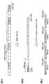
図7を参照して、ePDCCHが配置されるリソース領域において、各REに対するeREGインデックスの割当て法(各eREGを構成する複数のREの配置パターン制御)について説明する。なお、図7では、リソース領域として、通常サイクリックプレフィクス・通常サブフレームにおける1PRBペアを例に挙げて説明するがこれに限られない。
図7を参照して、ePDCCHが配置されるリソース領域において、各REに対するeREGインデックスの割当て法(各eREGを構成する複数のREの配置パターン制御)について説明する。なお、図7では、リソース領域として、通常サイクリックプレフィクス・通常サブフレームにおける1PRBペアを例に挙げて説明するがこれに限られない。
図7Aは、ePDCCHが配置されるリソース領域(1PRB)を示している。図7に示すリソース領域は、ePDCCHに利用可能な第1の領域~第3の領域と、DM-RSが配置されePDCCHに使用しない第4の領域とから構成される。第1の領域、第2の領域、第3の領域は、それぞれ既存のLTEシステム(又は、ePDCCHが配置されない他のリソース領域)で、PDSCH、サブフレームの先頭から1~3OFDMシンボルに配置される既存PDCCH、参照信号(CRS)が配置される領域に相当する。
ePDCCHが配置されるリソース領域において、参照信号(CRS)が配置される場合には、第1の領域と第2の領域をePDCCHに利用し、参照信号及び既存PDCCHが配置される場合には、第1の領域をePDCCHに利用する。つまり、リソース領域において、第1の領域がeCCEのマッピングに最も利用可能性が高い領域となる。
本実施の形態では、このようなリソース領域において、異なるeREGをそれぞれ構成するRE数が均一となり、且つ1eREGを構成する複数のREが複数のOFDMシンボルに分散するようにマッピングを行う。なお、異なるeREGをそれぞれ構成するRE数が均一とするとは、必ずしも異なるeREG間でRE数を同一とする場合に限られず、eREG間のRE数の差を出来るだけ小さくする(好ましくは、異なるeREGをそれぞれ構成するRE数の差を1以内とする)ことを指す。
例えば、第1の領域~第3の領域のREに対して、各eREGインデックス番号の割当てが均等となるように制御することにより、eREG間のサイズの均一化を図ることができる。また、各eREGインデックス番号を異なるOFDMシンボルのREに割当てることにより、各eREGを構成するREを複数のOFDMシンボルに分散することができる。以下に、各REに対応するeREGインデックス番号の割当て方法の一例について以下に説明する。
<ステップ1>
まず、ePDCCHに利用可能な領域(第1の領域~第3の領域)のREに対して、ePDCCHに利用できる可能性が高い領域のREから順に番号付け(ナンバリング)を行う(図7B参照)。例えば、第1の領域のREに対して番号付けを行った後、その他の信号に利用される可能性がある領域(第2の領域、第3の領域)に番号づけを行う。図7Bでは、第2の領域に番号付けを行った後に、第3の領域に番号付けを行う場合を示しているが、逆の順番に番号付けを行ってもよい。また、DM-RSが配置される第4の領域のREに対しては番号付けを行わない。
まず、ePDCCHに利用可能な領域(第1の領域~第3の領域)のREに対して、ePDCCHに利用できる可能性が高い領域のREから順に番号付け(ナンバリング)を行う(図7B参照)。例えば、第1の領域のREに対して番号付けを行った後、その他の信号に利用される可能性がある領域(第2の領域、第3の領域)に番号づけを行う。図7Bでは、第2の領域に番号付けを行った後に、第3の領域に番号付けを行う場合を示しているが、逆の順番に番号付けを行ってもよい。また、DM-RSが配置される第4の領域のREに対しては番号付けを行わない。
例えば、第1の領域において周波数及び時間が最も小さい領域のREを開始点として、周波数軸方向(図7Bの縦方向)に沿って順に番号付けを行う。また、各eREGを構成するREが出来るだけ分散されるように、図7Bに示すようにOFDMシンボル毎にサイクリックシフト(cyclic shift)を適用してもよい。
図7Bでは、まず、第1の領域のREに対して0~95まで番号付けを行う。続いて、第2の領域のREに対して3OFDMシンボル側から1OFDMシンボルに沿って、96~127まで番号付けを行った後、第3の領域のREに対して128~143まで番号付けを行う。
<ステップ2>
次に、ステップ1で各REに割当てたインデックスに対して、PRBペアに設けるeREGの数Nを用いてmodulo演算を適用する。この場合、PRBペアをN個のeREGに分割する場合に相当する。
次に、ステップ1で各REに割当てたインデックスに対して、PRBペアに設けるeREGの数Nを用いてmodulo演算を適用する。この場合、PRBペアをN個のeREGに分割する場合に相当する。
PRBペアに設けるeREGの数Nとしては、例えば、8、12、16、24又は36から選択することができる。これらの数のいずれかを選択することにより、各eREGに対してePDCCHに利用可能なRE数(144個)を均等に割当てることができるためである。特に、Nを8、16又は36とすることが好ましい。
N=8のmodulo演算を適用した場合を図8A、N=16のmodulo演算を適用した場合を図8Bに示す。図8Aの場合、ePDCCHとして利用可能なREに対して0~7のインデックス(eREGインデックス番号)が付される。この場合、インデックス番号0~7の8個のeREGは、それぞれ最大18個のREで構成される。また、図8Bの場合、ePDCCHとして使用可能なREに対して0~15のインデックス(eREGインデックス番号)が付される。この場合、インデックス番号0~15の16個のeREGは、それぞれ最大9個のREで構成される。
このように、ePDCCHに利用可能なREに順番にナンバリングした後に、modulo演算により各REが対応するeREGのインデックス番号を決定することにより、1eREGを構成する複数のREを複数のOFDMシンボルに分散することが可能となる。これにより、インデックス番号が異なるeREGのREを同じOFDMシンボルに多く配置して、各OFDMシンボル間で電力を均等にすることができるため、上記図6に示したeREGの割当てと比較して、電力の利用効率を向上することができる。
また、ePDCCHに利用可能な領域(第1の領域~第3の領域)のうち、ePDCCHに利用できる可能性が高い領域のREから順に番号付けを行うことにより、各領域に対して、インデックス番号が異なるeREGのREを均等に配置することができる。これにより、ePDCCH用に割当てられるリソース領域において、参照信号(CRS)及び/又は既存PDCCHが配置する場合であっても、各eREGのサイズを略均一化することが可能となる。
(eREGを割当て単位としたeCCEのマッピング法)
次に、複数のリソース領域に対するeCCEのマッピング方法について説明する。本実施の形態では、1eCCEを構成する複数のeREGを、拡張PDCCHが配置される複数のリソース領域(ここでは、PRBペア)にそれぞれ分散すると共に、各リソース領域に分散される各eREGのインデックス番号がそれぞれ異なるように下り制御情報(DCI)のマッピングを行う。以下に、図9を参照して、ePDCCHとして使用可能な複数のリソース領域(ここでは、PRBペア)に対して、eCCEをeREG単位でマッピングする方法の一例を説明する。なお、以下の説明では、eCCEを構成するREが36個(36RE/1eCCE)と定義する場合について説明するが、本実施の形態において、eCCEのサイズはこれに限られない。
次に、複数のリソース領域に対するeCCEのマッピング方法について説明する。本実施の形態では、1eCCEを構成する複数のeREGを、拡張PDCCHが配置される複数のリソース領域(ここでは、PRBペア)にそれぞれ分散すると共に、各リソース領域に分散される各eREGのインデックス番号がそれぞれ異なるように下り制御情報(DCI)のマッピングを行う。以下に、図9を参照して、ePDCCHとして使用可能な複数のリソース領域(ここでは、PRBペア)に対して、eCCEをeREG単位でマッピングする方法の一例を説明する。なお、以下の説明では、eCCEを構成するREが36個(36RE/1eCCE)と定義する場合について説明するが、本実施の形態において、eCCEのサイズはこれに限られない。
上述したように、1PRBペアにおいてePDCCHとして利用可能なREの総数が144個である場合に1eCCE=36REと仮定すると、1PRBペアに最大4eCCEを割当てることができる。この場合、システム帯域においてePDCCHを用いて送信する下り制御情報(DCI)に利用可能なeCCEの総数は、ePDCCHとして配置されるリソース領域×4となる。例えば、上記図5Aに示すように、拡張PDCCHが4個のPRBペア#1、#4、#8、#10に設定される場合には、利用できるeCCE数は16となる。
また、この場合、1eCCEを構成するeREG数は、“36/(144/N)”で求めることができる。つまり、1eCCEを構成するREの数36をeREGのサイズ(1eREGを構成するREの数)で割った値となる。なお、上述したように、Nは1リソース領域(例えば、1PRBペア)に設けるeREGの数に相当する。
例えば、1PRBペアに8個のeREGが含まれる場合(N=8)、1eCCEを構成するeREG数は2となる。また、1PRBペアに16個のeREGが含まれる場合(N=16)、1eCCEを構成するeREG数は4となる。
図9Aは、拡張PDCCHが配置されるリソース領域を4個(ここでは、PRBペア#1~#4)、1PRBペアに割当てられるeREG数Nを16とした場合の、各PRBペアと複数のeREG(eREGインデックス)との関係を示している。つまり、各PRBペア#1~#4に対して、eREG#0~#15がマッピングされる。なお、上記図8Bで示したように、各PRBペアにおいて、各eREG#0~#15を構成するREは分散して配置することができる。
また、1PRBペアに割当てられるeCCE数が4個である場合、1eCCEを構成するeREG数は4個となる。この場合、各PRB#1~#4に対して、図9Bに示すように複数のeCCE(ここでは、16個のeCCE#0~#15)をマッピングすることができる。
図9Bでは、1eCCEを構成する複数のeREGを異なるPRBペアに分散すると共に、異なるPRBペアに分散される複数のeREG同士のインデックス番号が異なるようにマッピングを行う。つまり、1eCCEを構成する複数のeREGは、それぞれ異なるeREGインデックス番号が付されて異なるPRBペアにマッピングされる。
このように、1eCCEを構成する複数のeREGを異なるPRBペアにマッピングすることにより周波数ダイバーシチ効果を得ることができる。また、1eCCEを異なるインデックス番号のeREGで構成することによりeCCE間のサイズが不均一となることを低減することができる。
具体的には、複数のPRBペアのeREGインデックスに対して順番にeCCEインデックスをマッピングする。また、この際、インデックス番号が連続するeCCEが異なるPRBペアに割当てられるようにマッピングを行う。例えば、図9Bに示すように、PRBペア#1~#4に割当てられるeREG#0に対してeCCE#0~#3を割当てる。同様に、PRBペア#1~#4に割当てられるeREG#1に対してeCCE#4~#7を割当てる。同様の手順を複数のeCCEが一巡するまで行う。これにより、PRBペア#1~#4に割当てられるeREG#0~#3に対してeCCE#0~#15が割当てられる。
続いて、複数のeCCEの割当てが一巡した後、サイクリックシフトを加えて同様に割当てを行う。例えば、図9Bに示すように、PRBペア#1~#4に割当てられるeREG#4に対してeCCE#0~#3を割当てる。但し、各eREGインデックスにおいて、各eCCEはPRBペア#2から#3、#4、#1の順に割当てを行う(サイクリックシフト)。
これにより、1eCCEを構成する複数のeREGを異なるPRBペアにマッピングすることができる。なお、サイクリックシフト量は、“PRBペア数(NPRB)/eCCE当たりのeREG数(NeREG)”で定めることができる。この場合、サイクリックシフト量は、1(=4/4)となる。
以上のマッピング法を繰り返し行うことにより、図9Bに示すように、各PRBペアに複数のeCCEをeREG単位でマッピングすることができる。例えば、eCCEインデックス番号が0のeCCE#0を構成する4個のeREGは、それぞれPRB#1~#4に分散して割当てられる。また、eCCE#0を構成する4個のeREGは、eREG#0(PRBペア#1)、eREG#4(PRBペア#2)、eREG#8(PRBペア#3)、eREG#12(PRBペア#4)となる。
このように、1eCCEを構成する複数のeREGを、それぞれ異なるeREGインデックス番号が付されて異なるPRBペアにマッピングすることにより、周波数ダイバーシチ効果を得ると共に、eCCE間のサイズの均一化を図ることができる。
また、各PRBペアにマッピングされるeREGを、上記図8に示すように、1PRB内の複数のOFDMシンボルのREに分散して配置することができる。これにより、電力の利用効率を向上すると共にeREG間及びeCCE間のサイズの均一化を効果的に図ることが可能となる。
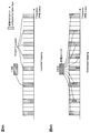
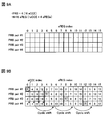
次に、拡張PDCCH用に4個のPRBペアが適用され、且つ1PRBペアが8個のeREGに分割される場合(N=8)のeCCEのマッピング方法を図10A、拡張PDCCH用に8個のPRBペアが適用され、且つ1PRBペアが8個のeREGに分割される場合(N=8)のeCCEのマッピング方法を図10Bに示す。なお、図10においても、1PBRあたりのeCCEの数を4個(例えば、1eCCE=36RE)と仮定している。
図10A、図10Bにおいても、上記図9で示したように、1eCCEを構成する複数のeREGを、それぞれ異なるeREGインデックス番号を付して異なるPRBペアにマッピングしている。なお、図10に示す場合、eCCEの総数(図10Aでは16個、図10Bでは32個)が1PRBペアに含まれるeREG数より大きくなる。この場合、上記図9で示したように、複数のPRBペアのeREGインデックスに対して順番にeCCEインデックスをマッピングすることにより、結果的にインデックス番号が連続するeCCEのeREGが異なるPRBペアに割当てられる。
例えば、eCCE#0とeCCE#1を構成するeREGをそれぞれ異なるPRBペアにマッピングする。この場合、図10Aでは、eCCE#0を構成する2個のeREGがPRBペア#1(eREG#0)とPRBペア#3(eREG#4)にマッピングされ、eCCE#1を構成する2個のeREGがPRBペア#2(eREG#0)とPRBペア#4(eREG#4)にマッピングされる。このように、インデックス番号が連続するeCCEのeREGを異なるPRBペアにマッピングすることにより、eCCEの結合レベル(アグリゲーションレベル)が高い場合であっても、周波数ダイバーシチ効果を得ることが可能となる。
なお、本実施の形態では、拡張PDCCHセットを構成する各周波数リソース単位がPRBペアであるものとして説明したが、これに限られるものではない。各周波数リソース単位は、PRBであってもよく、周波数方向に連続するPRBからなるRBG(Resource Block Group)などであってもよい。
以下、本実施の形態に係る無線通信システムについて詳細に説明する。
(無線通信システムの構成)
図11は、本実施の形態に係る無線通信システムのシステム構成の説明図である。なお、図11に示す無線通信システムは、例えば、LTEシステム或いは、その後継システムが包含されるシステムである。この無線通信システムでは、LTEシステムのシステム帯域を一単位とする複数の基本周波数ブロックを一体としたキャリアアグリゲーションが用いられている。また、この無線通信システムは、IMT-Advancedと呼ばれても良いし、4Gと呼ばれても良い。
図11は、本実施の形態に係る無線通信システムのシステム構成の説明図である。なお、図11に示す無線通信システムは、例えば、LTEシステム或いは、その後継システムが包含されるシステムである。この無線通信システムでは、LTEシステムのシステム帯域を一単位とする複数の基本周波数ブロックを一体としたキャリアアグリゲーションが用いられている。また、この無線通信システムは、IMT-Advancedと呼ばれても良いし、4Gと呼ばれても良い。
図11に示すように、無線通信システム1は、無線基地局10と、この無線基地局10と通信する複数のユーザ端末20とを含んで構成されている。無線基地局10は、上位局装置30と接続され、この上位局装置30は、コアネットワーク40と接続される。また、無線基地局10は、有線接続又は無線接続により相互に接続されている。各ユーザ端末20(20A、20B)は、セルC1、C2において無線基地局10と通信を行うことができる。なお、上位局装置30には、例えば、アクセスゲートウェイ装置、無線ネットワークコントローラ(RNC)、モビリティマネジメントエンティティ(MME)等が含まれるが、これに限定されない。
各ユーザ端末20は、LTE端末及びLTE-A端末を含むが、以下においては、特段の断りがない限りユーザ端末として説明を進める。
無線通信システム1においては、無線アクセス方式として、下りリンクについてはOFDMA(直交周波数分割多元接続)が、上りリンクについてはSC-FDMA(シングルキャリア-周波数分割多元接続)が適用されるが、上りリンクの無線アクセス方式はこれに限定されない。OFDMAは、周波数帯域を複数の狭い周波数帯域(サブキャリア)に分割し、各サブキャリアにデータをマッピングして通信を行うマルチキャリア伝送方式である。SC-FDMAは、システム帯域を端末毎に1つ又は連続したリソースブロックからなる帯域に分割し、複数の端末が互いに異なる帯域を用いることで、端末間の干渉を低減するシングルキャリア伝送方式である。
ここで、通信チャネルについて説明する。下りリンクの通信チャネルは、各ユーザ端末20で共有される下りデータチャネルとしてのPDSCH(Physical Downlink Shared Channel)と、下りL1/L2制御チャネル(PDCCH、PCFICH、PHICH)と、PDCCHを拡張した拡張PDCCHとを有する。PDSCHにより、ユーザデータ及び上位制御情報が伝送される。PDCCH(Physical Downlink Control Channel)により、PDSCHおよびPUSCHのスケジューリング情報等が伝送される。PCFICH(Physical Control Format Indicator Channel)により、PDCCHに用いるOFDMシンボル数が伝送される。PHICH(Physical Hybrid-ARQ Indicator Channel)により、PUSCHに対するHARQのACK/NACKが伝送される。
拡張PDCCHにより、PDSCH及びPUSCHのスケジューリング情報等が伝送される。拡張PDCCHは、PDSCHが割り当てられるリソース領域を用いてPDCCHの容量不足をサポートするために使用される。
上りリンクの通信チャネルは、各ユーザ端末で共有される上りデータチャネルとしてのPUSCH(Physical Uplink Shared Channel)と、上りリンクの制御チャネルであるPUCCH(Physical Uplink Control Channel)とを有する。このPUSCHにより、ユーザデータや上位制御情報が伝送される。また、PUCCHにより、下りリンクの無線品質情報(CQI:Channel Quality Indicator)、ACK/NACK等が伝送される。
図12は、本実施の形態に係る無線基地局10の全体構成図である。無線基地局10は、MIMO伝送のための複数の送受信アンテナ101と、アンプ部102と、送受信部103と、ベースバンド信号処理部104と、呼処理部105と、伝送路インターフェース106とを備えている。
下りリンクにより無線基地局10からユーザ端末20に送信されるユーザデータは、上位局装置30から伝送路インターフェース106を介してベースバンド信号処理部104に入力される。
ベースバンド信号処理部104では、PDCPレイヤの処理、ユーザデータの分割・結合、RLC(Radio Link Control)再送制御の送信処理などのRLCレイヤの送信処理、MAC(Medium Access Control)再送制御、例えば、HARQの送信処理、スケジューリング、伝送フォーマット選択、チャネル符号化、逆高速フーリエ変換(IFFT:Inverse Fast Fourier Transform)処理、プリコーディング処理が行われて各送受信部203に転送される。また、下りリンクの制御チャネルの信号に関しても、チャネル符号化や逆高速フーリエ変換等の送信処理が行われて、各送受信部103に転送される。
また、ベースバンド信号処理部104は、報知チャネルにより、ユーザ端末20に対して、当該セルにおける通信のための制御情報を通知する。当該セルにおける通信のための情報には、例えば、上りリンク又は下りリンクにおけるシステム帯域幅などが含まれる。
各送受信部103は、ベースバンド信号処理部104からアンテナ毎にプリコーディングして出力されたベースバンド信号を無線周波数帯に変換する。アンプ部102は、周波数変換された無線周波数信号を増幅して送受信アンテナ101により送信する。
一方、上りリンクによりユーザ端末20から無線基地局10に送信されるデータについては、各送受信アンテナ101で受信された無線周波数信号がそれぞれアンプ部102で増幅され、各送受信部103で周波数変換されてベースバンド信号に変換され、ベースバンド信号処理部104に入力される。
ベースバンド信号処理部104では、入力されたベースバンド信号に含まれるユーザデータに対して、FFT処理、IDFT処理、誤り訂正復号、MAC再送制御の受信処理、RLCレイヤ、PDCPレイヤの受信処理がなされ、伝送路インターフェース106を介して上位局装置30に転送される。呼処理部105は、通信チャネルの設定や解放等の呼処理や、無線基地局10の状態管理や、無線リソースの管理を行う。
図13は、本実施の形態に係るユーザ端末20の全体構成図である。ユーザ端末20は、MIMO伝送のための複数の送受信アンテナ201と、アンプ部202と、送受信部(受信部)203と、ベースバンド信号処理部204と、アプリケーション部205とを備えている。
下りリンクのデータについては、複数の送受信アンテナ201で受信された無線周波数信号がそれぞれアンプ部202で増幅され、送受信部203で周波数変換されてベースバンド信号に変換される。このベースバンド信号は、ベースバンド信号処理部204でFFT処理や、誤り訂正復号、再送制御の受信処理等がなされる。この下りリンクのデータの内、下りリンクのユーザデータは、アプリケーション部205に転送される。アプリケーション部205は、物理レイヤやMACレイヤより上位のレイヤに関する処理等を行う。また、下りリンクのデータの内、報知情報もアプリケーション部205に転送される。
一方、上りリンクのユーザデータについては、アプリケーション部205からベースバンド信号処理部204に入力される。ベースバンド信号処理部204では、再送制御(H-ARQ (Hybrid ARQ))の送信処理や、チャネル符号化、プリコーディング、DFT処理、IFFT処理等が行われて各送受信部203に転送される。送受信部203は、ベースバンド信号処理部204から出力されたベースバンド信号を無線周波数帯に変換する。その後、アンプ部202は、周波数変換された無線周波数信号を増幅して送受信アンテナ201により送信する。
図14は、本実施の形態に係る無線基地局10が有するベースバンド信号処理部104及び一部の上位レイヤの機能構成図である。なお、図14においては、下り(送信)用の機能構成を主に示しているが、無線基地局10は、上り(受信)用の機能構成を備えてもよい。
図14に示すように、無線基地局10は、上位レイヤ制御情報生成部300、データ生成部301、チャネル符号化部302、変調部303、マッピング部304、下り制御情報生成部305、共通制御情報生成部306、チャネル符号化部307、変調部308、制御チャネル多重部309、インタリーブ部310、測定用参照信号生成部311、IFFT部312、マッピング部313、復調用参照信号生成部314、ウェイト乗算部315、CP挿入部316、スケジューリング部317を具備する。
上位レイヤ制御情報生成部300は、ユーザ端末20毎に上位レイヤ制御情報を生成する。また、上位レイヤ制御情報は、上位レイヤシグナリング(例えば、RRCシグナリング)される制御情報であり、例えば、拡張PDCCHセットの割り当て情報(後述)などを含む。データ生成部301は、ユーザ端末20毎に下りユーザデータを生成する。
データ生成部301で生成された下りユーザデータと上位レイヤ制御情報生成部300で生成された上位レイヤ制御情報とは、PDSCHで伝送される下りデータとして、チャネル符号化部302に入力される。チャネル符号化部302は、各ユーザ端末20に対する下りデータを、各ユーザ端末20からのフィードバック情報に基づいて決定された符号化率に従ってチャネル符号化する。変調部303は、チャネル符号化された下りデータを各ユーザ端末20からのフィードバック情報に基づいて決定された変調方式に従って変調する。マッピング部304は、スケジューリング部317からの指示に従って、変調された下りデータをマッピングする。
下り制御情報生成部305は、ユーザ端末20毎に、UE固有(UE-specific)の下り制御情報(DCI)を生成する。UE固有の下り制御情報には、PDSCHの割り当て情報(DL assignment)、PUSCHの割り当て情報(UL grant)などが含まれる。共通制御情報生成部306は、セル共通(Cell-specific)の共通制御情報を生成する。
下り制御情報生成部305で生成された下り制御情報、共通制御情報生成部306で生成された共通制御情報は、PDCCH又は拡張PDCCHで伝送される下り制御情報として、チャネル符号化部307に入力される。PDCCで伝送される下り制御情報は、制御チャネル要素(CCE)単位で生成し、拡張PDCCHで伝送される下り制御情報は、拡張制御チャネル要素(eCCE)単位で生成することができる。なお、CCEとeCCEのサイズ(RE数)は異なっていてもよいし、同一であってもよい。
チャネル符号化部307は、入力された下り制御情報を、スケジューリング部317から指示された符号化率に従ってチャネル符号化する。変調部308は、チャネル符号化された下り制御情報をスケジューリング部317から指示された変調方式に従って変調する。
ここで、PDCCHで伝送される下り制御情報は、変調部308から制御チャネル多重部309に入力されて多重される。制御チャネル多重部309で多重された下り制御情報は、インタリーブ部310においてインタリーブされる。インタリーブされた下り制御情報は、測定用参照信号生成部311で生成された測定用参照信号(CSI-RS:Channel State Information-Reference Signal、CRS:Cell specific Reference Signalなど)とともに、IFFT部312に入力される。
一方、拡張PDCCHで伝送される下り制御情報は、変調部308からマッピング部313に入力される。マッピング部313は、スケジューリング部317からの指示に従って、下り制御情報を所定の割当て単位(例えば、eREG単位)でマッピングする。マッピング部313は、拡張PDCCH用に設定されるリソース領域に対して、下り制御情報が割当てられるeCCEをeREG単位で分散マッピング(Distributed Mapping)する。また、マッピング部313は、分散マッピングと局所マッピング(Localized Mapping)を切り替えて適用することも可能である。
例えば、マッピング部313は、分散マッピングを行う場合、1eCCEを構成する複数のeREGを、拡張PDCCHが配置される複数のリソース領域(PRBペア又はRBG)にそれぞれ分散すると共に、各リソース領域に分散される各eREGのインデックス番号がそれぞれ異なるようにマッピングを行う。例えば、上記図9で示したように、1eCCEを構成する複数のeREGについて、それぞれ異なるeREGインデックス番号を付して異なるPRBペアにマッピングすることにより、周波数ダイバーシチ効果を得ると共に、eCCE間のサイズの均一化を図ることができる。
また、マッピング部313は、上記図8に示すように、各PRBペアにマッピングされるeREGを、1PRB内の複数のOFDMシンボルのREに分散して配置することができる。これにより、電力の利用効率を向上すると共にeREG間及びeCCE間のサイズの均一化を効果的に図ることが可能となる。なお、各eCCEを構成するeREGがマッピングされる位置(リソース領域)、各eCCEを構成するeREGのインデックス番号、リソース領域において各eREGが対応するREパターン等は、スケジューリング部317からの情報に基づいて設定してもよいし、予め仕様で決定してもよい。
マッピングされた下り制御情報は、PDSCHで伝送される下りデータ(すなわち、マッピング部304でマッピングされた下りデータ)と、復調用参照信号生成部314で生成された復調用参照信号(DM-RS)とともに、ウェイト乗算部315に入力される。ウェイト乗算部315は、PDCSHで伝送される下りデータ、拡張PDCCHで伝送される下り制御情報、復調用参照信号に対して、ユーザ端末20固有のプリコーディングウェイトを乗算し、プリコーディングを行う。
プリコーディングされた送信データは、IFFT部312に入力され、逆高速フーリエ変換により周波数領域の信号から時系列の信号に変換される。IFFT部312からの出力信号には、CP挿入部316によりガードインターバルとして機能するサイクリックプリフィクス(CP)が挿入され、送受信部103に出力される。
スケジューリング部317は、PDSCHで伝送される下りデータ、拡張PDCCHで伝送される下り制御情報、PDCCHで伝送される下り制御情報のスケジューリングを行う。具体的には、スケジューリング部317は、上位局装置30からの指示情報や各ユーザ端末20からのフィードバック情報(例えば、CQI(Channel Quality Indicator)、RI(Rank Indicator)などを含むCSI(Channel State Information)など)に基づいて、無線リソースの割り当てを行う。
図15は、ユーザ端末20が有するベースバンド信号処理部204の機能構成図である。なお、図15においては、下り(受信)用の機能構成を主に示しているが、ユーザ端末20は、上り(送信)用の機能構成を備えてもよい。ユーザ端末20は、下り用の機能構成として、CP除去部401、FFT部402、デマッピング部403、デインタリーブ部404、PDCCH復調部405、PDSCH復調部406、拡張PDCCH復調部407、チャネル推定部408を具備する。
無線基地局10から受信データとして受信された下り信号は、CP除去部401でサイクリックプリフィクス(CP)が除去される。CPが除去された下り信号は、FFT部402へ入力される。FFT部402は、下り信号を高速フーリエ変換(FFT:Fast Fourier Transform)して時間領域の信号から周波数領域の信号に変換し、デマッピング部403へ入力する。デマッピング部403は、下り信号をデマッピングする。なお、デマッピング部403によるデマッピング処理は、アプリケーション部205から入力される上位レイヤ制御情報に基づいて行われる。デマッピング部403から出力された下り制御情報は、デインタリーブ部404でデインタリーブされる。
PDCCH復調部405は、チャネル推定部408によるチャネル推定結果に基づいて、デインタリーブ部404から出力された下り制御情報(DCI)のブラインド復号、復調、チャネル復号などを行う。具体的には、PDCCH復調部405は、無線基地局10から予め通知されたサーチスペース候補、または予め決められたサーチスペース候補をブラインド復号して、下り制御情報を取得する。
PDSCH復調部406は、チャネル推定部408によるチャネル推定結果に基づいて、デマッピング部403から出力された下りデータの復調、チャネル復号などを行う。具体的には、PDSCH復調部406は、PDCCH復調部405又は拡張PDCCH復調部407で復調された下り制御情報(例えば、DL grantなどの下りスケジューリング情報)に基づいて自端末に割り当てられたPDSCHを復調し、自端末宛ての下りデータ(下りユーザデータ及び上位レイヤ制御情報)を取得する。
拡張PDCCH復調部407は、チャネル推定部408によるチャネル推定結果に基づいて、デマッピング部403から出力された拡張PDCCH復調部407のブラインド復号、復調、チャネル復号などを行う。
チャネル推定部408は、復調用参照信号(DM-RS)、測定用参照信号(CRS、CSI-RS)などを用いてチャネル推定を行う。チャネル推定部408は、測定用参照信号(CRS、CSI-RS)によるチャネル推定結果をPDCCH復調部405に出力する。一方、チャネル推定部408は、復調用参照信号(DM-RS)によるチャネル推定結果をPDSCH復調部406及び拡張PDCCH復調部407に出力する。ユーザ端末20に固有の復調用参照信号(DM-RS)を用いた復調により、PDSCH及び拡張PDCCHについては、ビームフォーミングゲインを得ることができる。
以上のように、本実施の形態に係る無線通信システム1によれば、無線基地局10は、拡張制御チャネル要素(eCCE)単位で下り制御情報を生成し、拡張下り制御チャネル用に配置される複数のリソース領域に、下り制御情報をeREG単位でマッピングする。この場合、無線基地局10は、1eCCEを構成する複数のeREGを、複数のリソース領域にそれぞれ分散すると共に、各リソース領域に分散される各eREGのインデックス番号がそれぞれ異なるようにマッピングを行う。また、無線基地局10は、各PRBペアにマッピングされるeREGを、1PRB内の複数のOFDMシンボルのREに分散して配置する。これにより、周波数ダイバーシチ効果、電力の利用効率を向上すると共にeREG間及びeCCE間のサイズの均一化を効果的に図ることが可能となる。
以上、上述の実施形態を用いて本発明について詳細に説明したが、当業者にとっては、本発明が本明細書中に説明した実施形態に限定されるものではないということは明らかである。本発明は、特許請求の範囲の記載により定まる本発明の趣旨及び範囲を逸脱することなく修正及び変更態様として実施することができる。従って、本明細書の記載は、例示説明を目的とするものであり、本発明に対して何ら制限的な意味を有するものではない。
本出願は、2012年7月23日出願の特願2012-162819に基づく。この内容は、全てここに含めておく。
Claims (10)
- 無線基地局が下り共有データチャネルと周波数分割多重される拡張下り制御チャネルを介して各ユーザ端末に対する下り制御情報を送信する無線通信システムにおける無線通信方法であって、
前記無線基地局は、複数の拡張リソース要素グループ(eREG)で構成される拡張制御チャネル要素(eCCE)単位で前記下り制御情報を生成する工程と、前記拡張下り制御チャネル用の複数のリソース領域に、前記下り制御情報を拡張リソース要素グループ(eREG)単位でマッピングする工程と、を有し、
前記拡張リソース要素グループ(eREG)は複数のリソース要素(RE)で構成されており、前記無線基地局は、前記各リソース領域において、異なる拡張リソース要素グループ(eREG)をそれぞれ構成するリソース要素(RE)数が均一となり、且つ拡張リソース要素グループ(1eREG)を構成する複数のリソース要素(RE)が複数のOFDMシンボルに分散するようにマッピングを行うことを特徴とする無線通信方法。 - 拡張リソース要素グループに付されるインデックス番号と、各リソース領域に対する割当て位置が対応しており、前記無線基地局は、拡張制御チャネル要素(1eCCE)を構成する複数の拡張リソース要素グループ(eREG)に対して、異なるインデックス番号を設定すると共に異なるリソース領域に分散してマッピングすることを特徴とする請求項1に記載の無線通信方法。
- 前記無線基地局は、インデックス番号が連続する拡張制御チャネル要素(eCCE)を構成する拡張リソース要素グループ(eREG)をそれぞれ異なるリソース領域にマッピングすることを特徴とする請求項1又は請求項2に記載の無線通信方法。
- 前記無線基地局は、前記拡張リソース要素グループ(eREG)を、復調用参照信号(DM-RS)が割当てられる領域を除いた領域のリソース要素(RE)に割当て、
既存システムにおいて、下り共有データチャネルが割当てられる第1の領域、制御チャネルが割当てられるサブフレームの先頭から3OFDMシンボルまでの第2の領域、セル固有参照信号(CRS)が割当てられる第3の領域のリソース要素(RE)に対して、それぞれインデックス番号が異なる拡張リソース要素グループ(eREG)が均一に割当てられることを特徴とする請求項1又は請求項2に記載の無線通信方法。 - 前記第1の領域、前記第2の領域、前記第3の領域のリソース要素(RE)に対して連続する番号を順にナンバリングした後、ナンバリングされた番号に対し、前記リソース領域に含まれる拡張リソース要素グループ(eREG)数Nを用いたmodulo演算を適用することにより、各リソース要素(RE)に対応する拡張リソース要素グループ(eREG)のインデックス番号が決定されることを特徴とする請求項4に記載の無線通信方法。
- 前記リソース領域は、物理リソースリブロック(PRB)又はリソースブロックグループ(RBG)であることを特徴とする請求項1又は請求項2に記載の無線通信方法。
- 無線基地局が下り共有データチャネルと周波数分割多重される拡張下り制御チャネルを介して各ユーザ端末に対する下り制御情報を送信する無線通信システムであって、
前記無線基地局は、複数の拡張リソース要素グループ(eREG)で構成される拡張制御チャネル要素(eCCE)単位で前記下り制御情報を生成する生成部と、前記拡張下り制御チャネル用の複数のリソース領域に、前記下り制御情報を拡張リソース要素グループ(eREG)単位でマッピングするマッピング部と、を有し、
前記拡張リソース要素グループ(eREG)は複数のリソース要素(RE)で構成されており、前記マッピング部は、前記各リソース領域において、異なる拡張リソース要素グループ(eREG)をそれぞれ構成するリソース要素(RE)数が均一となり、且つ拡張リソース要素グループ(1eREG)を構成する複数のリソース要素(RE)が複数のOFDMシンボルに分散するようにマッピングを行うことを特徴とする無線通信システム。 - 拡張リソース要素グループに付されるインデックス番号と、各リソース領域に対する割当て位置が対応しており、前記マッピング部は、拡張制御チャネル要素(1eCCE)を構成する複数の拡張リソース要素グループ(eREG)に対して、異なるインデックス番号を設定すると共に異なるリソース領域に分散してマッピングすることを特徴とする請求項7に記載の無線通信システム。
- 下り共有データチャネルと周波数分割多重される拡張下り制御チャネルを介して各ユーザ端末に対する下り制御情報を送信する無線基地局であって、
複数の拡張リソース要素グループ(eREG)で構成される拡張制御チャネル要素(eCCE)単位で前記下り制御情報を生成する生成部と、
前記拡張下り制御チャネル用の複数のリソース領域に、前記下り制御情報を拡張リソース要素グループ(eREG)単位でマッピングするマッピング部と、を有し、
前記拡張リソース要素グループ(eREG)は複数のリソース要素(RE)で構成されており、前記マッピング部は、前記各リソース領域において、異なる拡張リソース要素グループ(eREG)をそれぞれ構成するリソース要素(RE)数が均一となり、且つ拡張リソース要素グループ(1eREG)を構成する複数のリソース要素(RE)が複数のOFDMシンボルに分散するようにマッピングを行うことを特徴とする無線基地局。 - 拡張リソース要素グループに付されるインデックス番号と、各リソース領域に対する割当て位置が対応しており、前記マッピング部は、拡張制御チャネル要素(1eCCE)を構成する複数の拡張リソース要素グループ(eREG)に対して、異なるインデックス番号を設定すると共に異なるリソース領域に分散してマッピングすることを特徴とする請求項9に記載の無線基地局。
Priority Applications (4)
| Application Number | Priority Date | Filing Date | Title |
|---|---|---|---|
| CN201380037956.2A CN104488342B (zh) | 2012-07-23 | 2013-07-22 | 无线通信方法、无线通信系统以及无线基站 |
| EP13823237.6A EP2876962B1 (en) | 2012-07-23 | 2013-07-22 | Wireless communications method, wireless communications system, and wireless base station |
| MX2015000901A MX341721B (es) | 2012-07-23 | 2013-07-22 | Metodo de radiocomunicacion, sistema de radiocomunicacion y estacion de base de radio. |
| US14/416,155 US9491749B2 (en) | 2012-07-23 | 2013-07-22 | Radio communication method, radio communication system and radio base station |
Applications Claiming Priority (2)
| Application Number | Priority Date | Filing Date | Title |
|---|---|---|---|
| JP2012162819A JP5829987B2 (ja) | 2012-07-23 | 2012-07-23 | 無線通信方法、無線通信システム及び無線基地局 |
| JP2012-162819 | 2012-07-23 |
Publications (1)
| Publication Number | Publication Date |
|---|---|
| WO2014017440A1 true WO2014017440A1 (ja) | 2014-01-30 |
Family
ID=49997251
Family Applications (1)
| Application Number | Title | Priority Date | Filing Date |
|---|---|---|---|
| PCT/JP2013/069803 Ceased WO2014017440A1 (ja) | 2012-07-23 | 2013-07-22 | 無線通信方法、無線通信システム及び無線基地局 |
Country Status (7)
| Country | Link |
|---|---|
| US (1) | US9491749B2 (ja) |
| EP (1) | EP2876962B1 (ja) |
| JP (1) | JP5829987B2 (ja) |
| CN (1) | CN104488342B (ja) |
| MX (1) | MX341721B (ja) |
| PT (1) | PT2876962T (ja) |
| WO (1) | WO2014017440A1 (ja) |
Cited By (2)
| Publication number | Priority date | Publication date | Assignee | Title |
|---|---|---|---|---|
| WO2016033962A1 (zh) * | 2014-09-05 | 2016-03-10 | 中兴通讯股份有限公司 | 一种信道复用的方法和装置 |
| WO2016163922A1 (en) * | 2015-04-10 | 2016-10-13 | Telefonaktiebolaget Lm Ericsson (Publ) | Radio access node, wireless device and methods performed therein |
Families Citing this family (32)
| Publication number | Priority date | Publication date | Assignee | Title |
|---|---|---|---|---|
| CN106656448B (zh) * | 2012-01-13 | 2020-06-26 | 华为技术有限公司 | 用于生成和传输解调参考信号的方法 |
| JP5781028B2 (ja) * | 2012-07-23 | 2015-09-16 | 株式会社Nttドコモ | 無線通信方法、無線基地局、ユーザ端末及び無線通信システム |
| WO2014019208A1 (zh) | 2012-08-02 | 2014-02-06 | 华为技术有限公司 | 传输控制信息的方法、装置及系统 |
| CN103718630A (zh) | 2012-08-02 | 2014-04-09 | 华为技术有限公司 | 增强型物理下行控制信道传输方法及设备 |
| WO2014027409A1 (ja) | 2012-08-15 | 2014-02-20 | 富士通株式会社 | 通信システム、無線基地局、無線端末および通信方法 |
| KR101562702B1 (ko) | 2012-09-14 | 2015-10-22 | 주식회사 케이티 | 송수신포인트의 제어 정보 전송 방법 및 그 송수신포인트, 단말의 제어 정보 수신 방법 및 그 단말 |
| KR101562694B1 (ko) * | 2012-09-18 | 2015-10-22 | 주식회사 케이티 | 송수신포인트의 제어 정보 전송 방법 및 그 송수신포인트, 단말의 제어 정보 수신 방법 및 그 단말 |
| WO2014046425A2 (en) | 2012-09-18 | 2014-03-27 | Kt Corporation | Transmission and reception of control information |
| JP6115840B2 (ja) | 2013-01-29 | 2017-04-19 | サン パテント トラスト | 基地局、端末、送信方法及び受信方法 |
| US10652768B2 (en) * | 2015-04-20 | 2020-05-12 | Qualcomm Incorporated | Control channel based broadcast messaging |
| CN107005375B (zh) * | 2015-07-16 | 2021-01-29 | 华为技术有限公司 | 终端到终端数据传输方法及设备 |
| US9955484B2 (en) * | 2015-08-06 | 2018-04-24 | Nokia Technologies Oy | Position information based access to a shared radio access channel |
| CN108293252B (zh) * | 2016-03-31 | 2023-08-01 | 索尼公司 | 终端装置、基站装置和通信方法 |
| RU2699831C1 (ru) * | 2016-04-21 | 2019-09-11 | Телефонактиеболагет Лм Эрикссон (Пабл) | Способы и устройства для управления идентификатором соты в gsm сети |
| CN109076044A (zh) * | 2016-05-13 | 2018-12-21 | 富士通株式会社 | 资源映射方法、装置以及通信系统 |
| MX2019005155A (es) * | 2016-11-03 | 2019-06-20 | Guangdong Oppo Mobile Telecommunications Corp Ltd | Metodo de transmision de se?ales, dispositivo de terminal y dispositivo de red. |
| EP3491770B1 (en) | 2016-11-04 | 2020-01-08 | Telefonaktiebolaget LM Ericsson (publ) | Short physical downlink control channel (spdcch) mapping design |
| KR102431635B1 (ko) | 2016-11-04 | 2022-08-12 | 삼성전자 주식회사 | 무선 셀룰라 통신 시스템에서 지연 감소를 위한 적응적 재전송 방법 및 장치 |
| WO2018098683A1 (zh) | 2016-11-30 | 2018-06-07 | 广东欧珀移动通信有限公司 | 传输信息的方法、终端设备和网络设备 |
| US11350392B2 (en) * | 2017-01-20 | 2022-05-31 | Ntt Docomo, Inc. | User terminal and radio communication method |
| KR20240159031A (ko) | 2017-02-03 | 2024-11-05 | 주식회사 윌러스표준기술연구소 | 무선 통신 시스템에서 레퍼런스 신호 및 데이터 채널의 송수신 방법, 장치, 및 시스템 |
| WO2018144641A1 (en) * | 2017-02-06 | 2018-08-09 | Intel IP Corporation | Downlink control signaling segmentation |
| JP7082969B2 (ja) * | 2017-03-17 | 2022-06-09 | パナソニック インテレクチュアル プロパティ コーポレーション オブ アメリカ | 通信装置、通信方法及び集積回路 |
| CN110324134B (zh) * | 2017-08-30 | 2021-12-10 | 中国信息通信研究院 | 一种下行控制信道的搜索空间配置方法和装置 |
| WO2019049351A1 (ja) * | 2017-09-08 | 2019-03-14 | 株式会社Nttドコモ | ユーザ端末および無線通信方法 |
| US10652069B2 (en) * | 2017-10-26 | 2020-05-12 | Qualcomm Incorporated | Resource element group mapping for a downlink control channel |
| EP3713320A4 (en) * | 2017-11-17 | 2021-06-23 | Ntt Docomo, Inc. | USER TERMINAL DEVICE AND WIRELESS COMMUNICATION PROCEDURE |
| EP3720212B1 (en) * | 2017-12-01 | 2023-10-04 | NTT DoCoMo, Inc. | User terminal and wireless communication method |
| WO2019168051A1 (ja) * | 2018-03-01 | 2019-09-06 | 株式会社Nttドコモ | ユーザ端末及び無線通信方法 |
| EP3823337B1 (en) * | 2018-07-13 | 2024-02-21 | NTT DoCoMo, Inc. | User equipment and base station |
| US11212062B2 (en) | 2018-09-28 | 2021-12-28 | Qualcomm Incorporated | Limits on quantity of downlink control information (DCI) processed |
| CN111181666B (zh) * | 2018-11-12 | 2021-03-12 | 大唐移动通信设备有限公司 | 一种时频调整方法及装置 |
Family Cites Families (3)
| Publication number | Priority date | Publication date | Assignee | Title |
|---|---|---|---|---|
| KR100956828B1 (ko) * | 2008-11-13 | 2010-05-11 | 엘지전자 주식회사 | 반(半)-지속적 스케줄링의 비활성화를 지시하는 방법 및 이를 이용한 장치 |
| JP5906532B2 (ja) | 2012-03-15 | 2016-04-20 | シャープ株式会社 | 基地局装置、端末装置、通信方法および集積回路 |
| CN104272614B (zh) * | 2012-03-28 | 2017-06-23 | Lg电子株式会社 | 在无线通信系统中分配用于下行链路控制信道的资源的方法 |
-
2012
- 2012-07-23 JP JP2012162819A patent/JP5829987B2/ja active Active
-
2013
- 2013-07-22 CN CN201380037956.2A patent/CN104488342B/zh active Active
- 2013-07-22 MX MX2015000901A patent/MX341721B/es active IP Right Grant
- 2013-07-22 WO PCT/JP2013/069803 patent/WO2014017440A1/ja not_active Ceased
- 2013-07-22 US US14/416,155 patent/US9491749B2/en active Active
- 2013-07-22 PT PT13823237T patent/PT2876962T/pt unknown
- 2013-07-22 EP EP13823237.6A patent/EP2876962B1/en active Active
Non-Patent Citations (6)
| Title |
|---|
| "DCI multiplexing by eREG", 3GPP TSG-RAN WG1 RL-122001, 25 May 2012 (2012-05-25), XP050600293 * |
| "Mapping of ePDCCH to RE", 3GPP TSG-RAN WG1 #69 RL-122000, 25 May 2012 (2012-05-25), XP050600292 * |
| "Multiplexing of ePDCCH for different users", 3GPP TSG RAN WG1 MEETING #68BIS RL-121288, 30 March 2012 (2012-03-30), XP050599578 * |
| "Views on Resource Mapping for ePDCCH", 3GPP TSG RAN WG1 MEETING #69 RL-121977, 25 May 2012 (2012-05-25), XP050601030 * |
| 3RD GENERATION PARTNERSHIP PROJECT: "Requirements for Evolved UTRA and Evolved UTRAN", 3GPP TR 25.913 |
| See also references of EP2876962A4 |
Cited By (3)
| Publication number | Priority date | Publication date | Assignee | Title |
|---|---|---|---|---|
| WO2016033962A1 (zh) * | 2014-09-05 | 2016-03-10 | 中兴通讯股份有限公司 | 一种信道复用的方法和装置 |
| CN105471561A (zh) * | 2014-09-05 | 2016-04-06 | 中兴通讯股份有限公司 | 一种信道复用的方法和装置 |
| WO2016163922A1 (en) * | 2015-04-10 | 2016-10-13 | Telefonaktiebolaget Lm Ericsson (Publ) | Radio access node, wireless device and methods performed therein |
Also Published As
| Publication number | Publication date |
|---|---|
| MX2015000901A (es) | 2015-04-10 |
| JP5829987B2 (ja) | 2015-12-09 |
| PT2876962T (pt) | 2019-03-27 |
| JP2014023108A (ja) | 2014-02-03 |
| US9491749B2 (en) | 2016-11-08 |
| US20150181573A1 (en) | 2015-06-25 |
| EP2876962B1 (en) | 2019-02-13 |
| MX341721B (es) | 2016-08-31 |
| EP2876962A4 (en) | 2016-03-16 |
| CN104488342B (zh) | 2018-09-18 |
| EP2876962A1 (en) | 2015-05-27 |
| CN104488342A (zh) | 2015-04-01 |
Similar Documents
| Publication | Publication Date | Title |
|---|---|---|
| JP5829987B2 (ja) | 無線通信方法、無線通信システム及び無線基地局 | |
| JP5809103B2 (ja) | 無線基地局、ユーザ端末、無線通信システム及び無線通信方法 | |
| JP5771177B2 (ja) | 無線基地局、ユーザ端末、無線通信システム及び無線通信方法 | |
| JP6219018B2 (ja) | 無線基地局装置、ユーザ端末、無線通信システム及び無線通信方法 | |
| JP5554799B2 (ja) | 無線基地局装置、ユーザ端末、無線通信システム及び無線通信方法 | |
| JP5726819B2 (ja) | 復号方法、無線基地局、ユーザ端末及び無線通信システム | |
| JP5487229B2 (ja) | 無線基地局装置、ユーザ端末、無線通信システム及び無線通信方法 | |
| JP6105693B2 (ja) | 無線通信方法、無線通信システム及び無線基地局 | |
| JP5898874B2 (ja) | ユーザ端末、無線基地局装置、無線通信システム及び無線通信方法 | |
| JP6068860B2 (ja) | 無線通信方法、無線基地局、ユーザ端末及び無線通信システム | |
| JP5793131B2 (ja) | 無線基地局、ユーザ端末、無線通信システム及び無線通信方法 | |
| JP6106725B2 (ja) | 無線基地局、ユーザ端末、無線通信システム及び無線通信方法 |
Legal Events
| Date | Code | Title | Description |
|---|---|---|---|
| 121 | Ep: the epo has been informed by wipo that ep was designated in this application |
Ref document number: 13823237 Country of ref document: EP Kind code of ref document: A1 |
|
| WWE | Wipo information: entry into national phase |
Ref document number: MX/A/2015/000901 Country of ref document: MX |
|
| WWE | Wipo information: entry into national phase |
Ref document number: 14416155 Country of ref document: US |
|
| NENP | Non-entry into the national phase |
Ref country code: DE |
|
| WWE | Wipo information: entry into national phase |
Ref document number: 2013823237 Country of ref document: EP |