WO2014017589A1 - 方向性電磁鋼板の製造方法 - Google Patents
方向性電磁鋼板の製造方法 Download PDFInfo
- Publication number
- WO2014017589A1 WO2014017589A1 PCT/JP2013/070185 JP2013070185W WO2014017589A1 WO 2014017589 A1 WO2014017589 A1 WO 2014017589A1 JP 2013070185 W JP2013070185 W JP 2013070185W WO 2014017589 A1 WO2014017589 A1 WO 2014017589A1
- Authority
- WO
- WIPO (PCT)
- Prior art keywords
- mass
- annealing
- steel sheet
- hot
- temperature
- Prior art date
- Legal status (The legal status is an assumption and is not a legal conclusion. Google has not performed a legal analysis and makes no representation as to the accuracy of the status listed.)
- Ceased
Links
Images


Classifications
-
- C—CHEMISTRY; METALLURGY
- C21—METALLURGY OF IRON
- C21D—MODIFYING THE PHYSICAL STRUCTURE OF FERROUS METALS; GENERAL DEVICES FOR HEAT TREATMENT OF FERROUS OR NON-FERROUS METALS OR ALLOYS; MAKING METAL MALLEABLE, e.g. BY DECARBURISATION OR TEMPERING
- C21D6/00—Heat treatment of ferrous alloys
- C21D6/004—Heat treatment of ferrous alloys containing Cr and Ni
-
- C—CHEMISTRY; METALLURGY
- C21—METALLURGY OF IRON
- C21D—MODIFYING THE PHYSICAL STRUCTURE OF FERROUS METALS; GENERAL DEVICES FOR HEAT TREATMENT OF FERROUS OR NON-FERROUS METALS OR ALLOYS; MAKING METAL MALLEABLE, e.g. BY DECARBURISATION OR TEMPERING
- C21D6/00—Heat treatment of ferrous alloys
- C21D6/005—Heat treatment of ferrous alloys containing Mn
-
- C—CHEMISTRY; METALLURGY
- C21—METALLURGY OF IRON
- C21D—MODIFYING THE PHYSICAL STRUCTURE OF FERROUS METALS; GENERAL DEVICES FOR HEAT TREATMENT OF FERROUS OR NON-FERROUS METALS OR ALLOYS; MAKING METAL MALLEABLE, e.g. BY DECARBURISATION OR TEMPERING
- C21D6/00—Heat treatment of ferrous alloys
- C21D6/008—Heat treatment of ferrous alloys containing Si
-
- C—CHEMISTRY; METALLURGY
- C21—METALLURGY OF IRON
- C21D—MODIFYING THE PHYSICAL STRUCTURE OF FERROUS METALS; GENERAL DEVICES FOR HEAT TREATMENT OF FERROUS OR NON-FERROUS METALS OR ALLOYS; MAKING METAL MALLEABLE, e.g. BY DECARBURISATION OR TEMPERING
- C21D8/00—Modifying the physical properties of ferrous metals or ferrous alloys by deformation combined with, or followed by, heat treatment
- C21D8/12—Modifying the physical properties of ferrous metals or ferrous alloys by deformation combined with, or followed by, heat treatment during manufacturing of articles with special electromagnetic properties
-
- C—CHEMISTRY; METALLURGY
- C21—METALLURGY OF IRON
- C21D—MODIFYING THE PHYSICAL STRUCTURE OF FERROUS METALS; GENERAL DEVICES FOR HEAT TREATMENT OF FERROUS OR NON-FERROUS METALS OR ALLOYS; MAKING METAL MALLEABLE, e.g. BY DECARBURISATION OR TEMPERING
- C21D8/00—Modifying the physical properties of ferrous metals or ferrous alloys by deformation combined with, or followed by, heat treatment
- C21D8/12—Modifying the physical properties of ferrous metals or ferrous alloys by deformation combined with, or followed by, heat treatment during manufacturing of articles with special electromagnetic properties
- C21D8/1216—Modifying the physical properties of ferrous metals or ferrous alloys by deformation combined with, or followed by, heat treatment during manufacturing of articles with special electromagnetic properties characterised by the working steps
- C21D8/1222—Hot rolling
-
- C—CHEMISTRY; METALLURGY
- C21—METALLURGY OF IRON
- C21D—MODIFYING THE PHYSICAL STRUCTURE OF FERROUS METALS; GENERAL DEVICES FOR HEAT TREATMENT OF FERROUS OR NON-FERROUS METALS OR ALLOYS; MAKING METAL MALLEABLE, e.g. BY DECARBURISATION OR TEMPERING
- C21D8/00—Modifying the physical properties of ferrous metals or ferrous alloys by deformation combined with, or followed by, heat treatment
- C21D8/12—Modifying the physical properties of ferrous metals or ferrous alloys by deformation combined with, or followed by, heat treatment during manufacturing of articles with special electromagnetic properties
- C21D8/1216—Modifying the physical properties of ferrous metals or ferrous alloys by deformation combined with, or followed by, heat treatment during manufacturing of articles with special electromagnetic properties characterised by the working steps
- C21D8/1233—Cold rolling
-
- C—CHEMISTRY; METALLURGY
- C21—METALLURGY OF IRON
- C21D—MODIFYING THE PHYSICAL STRUCTURE OF FERROUS METALS; GENERAL DEVICES FOR HEAT TREATMENT OF FERROUS OR NON-FERROUS METALS OR ALLOYS; MAKING METAL MALLEABLE, e.g. BY DECARBURISATION OR TEMPERING
- C21D8/00—Modifying the physical properties of ferrous metals or ferrous alloys by deformation combined with, or followed by, heat treatment
- C21D8/12—Modifying the physical properties of ferrous metals or ferrous alloys by deformation combined with, or followed by, heat treatment during manufacturing of articles with special electromagnetic properties
- C21D8/1244—Modifying the physical properties of ferrous metals or ferrous alloys by deformation combined with, or followed by, heat treatment during manufacturing of articles with special electromagnetic properties characterised by the heat treatment
- C21D8/1255—Modifying the physical properties of ferrous metals or ferrous alloys by deformation combined with, or followed by, heat treatment during manufacturing of articles with special electromagnetic properties characterised by the heat treatment with diffusion of elements, e.g. decarburising, nitriding
-
- C—CHEMISTRY; METALLURGY
- C21—METALLURGY OF IRON
- C21D—MODIFYING THE PHYSICAL STRUCTURE OF FERROUS METALS; GENERAL DEVICES FOR HEAT TREATMENT OF FERROUS OR NON-FERROUS METALS OR ALLOYS; MAKING METAL MALLEABLE, e.g. BY DECARBURISATION OR TEMPERING
- C21D8/00—Modifying the physical properties of ferrous metals or ferrous alloys by deformation combined with, or followed by, heat treatment
- C21D8/12—Modifying the physical properties of ferrous metals or ferrous alloys by deformation combined with, or followed by, heat treatment during manufacturing of articles with special electromagnetic properties
- C21D8/1244—Modifying the physical properties of ferrous metals or ferrous alloys by deformation combined with, or followed by, heat treatment during manufacturing of articles with special electromagnetic properties characterised by the heat treatment
- C21D8/1261—Modifying the physical properties of ferrous metals or ferrous alloys by deformation combined with, or followed by, heat treatment during manufacturing of articles with special electromagnetic properties characterised by the heat treatment following hot rolling
-
- C—CHEMISTRY; METALLURGY
- C21—METALLURGY OF IRON
- C21D—MODIFYING THE PHYSICAL STRUCTURE OF FERROUS METALS; GENERAL DEVICES FOR HEAT TREATMENT OF FERROUS OR NON-FERROUS METALS OR ALLOYS; MAKING METAL MALLEABLE, e.g. BY DECARBURISATION OR TEMPERING
- C21D8/00—Modifying the physical properties of ferrous metals or ferrous alloys by deformation combined with, or followed by, heat treatment
- C21D8/12—Modifying the physical properties of ferrous metals or ferrous alloys by deformation combined with, or followed by, heat treatment during manufacturing of articles with special electromagnetic properties
- C21D8/1244—Modifying the physical properties of ferrous metals or ferrous alloys by deformation combined with, or followed by, heat treatment during manufacturing of articles with special electromagnetic properties characterised by the heat treatment
- C21D8/1266—Modifying the physical properties of ferrous metals or ferrous alloys by deformation combined with, or followed by, heat treatment during manufacturing of articles with special electromagnetic properties characterised by the heat treatment between cold rolling steps
-
- C—CHEMISTRY; METALLURGY
- C21—METALLURGY OF IRON
- C21D—MODIFYING THE PHYSICAL STRUCTURE OF FERROUS METALS; GENERAL DEVICES FOR HEAT TREATMENT OF FERROUS OR NON-FERROUS METALS OR ALLOYS; MAKING METAL MALLEABLE, e.g. BY DECARBURISATION OR TEMPERING
- C21D8/00—Modifying the physical properties of ferrous metals or ferrous alloys by deformation combined with, or followed by, heat treatment
- C21D8/12—Modifying the physical properties of ferrous metals or ferrous alloys by deformation combined with, or followed by, heat treatment during manufacturing of articles with special electromagnetic properties
- C21D8/1244—Modifying the physical properties of ferrous metals or ferrous alloys by deformation combined with, or followed by, heat treatment during manufacturing of articles with special electromagnetic properties characterised by the heat treatment
- C21D8/1272—Final recrystallisation annealing
-
- C—CHEMISTRY; METALLURGY
- C21—METALLURGY OF IRON
- C21D—MODIFYING THE PHYSICAL STRUCTURE OF FERROUS METALS; GENERAL DEVICES FOR HEAT TREATMENT OF FERROUS OR NON-FERROUS METALS OR ALLOYS; MAKING METAL MALLEABLE, e.g. BY DECARBURISATION OR TEMPERING
- C21D8/00—Modifying the physical properties of ferrous metals or ferrous alloys by deformation combined with, or followed by, heat treatment
- C21D8/12—Modifying the physical properties of ferrous metals or ferrous alloys by deformation combined with, or followed by, heat treatment during manufacturing of articles with special electromagnetic properties
- C21D8/1277—Modifying the physical properties of ferrous metals or ferrous alloys by deformation combined with, or followed by, heat treatment during manufacturing of articles with special electromagnetic properties involving a particular surface treatment
- C21D8/1283—Application of a separating or insulating coating
-
- C—CHEMISTRY; METALLURGY
- C21—METALLURGY OF IRON
- C21D—MODIFYING THE PHYSICAL STRUCTURE OF FERROUS METALS; GENERAL DEVICES FOR HEAT TREATMENT OF FERROUS OR NON-FERROUS METALS OR ALLOYS; MAKING METAL MALLEABLE, e.g. BY DECARBURISATION OR TEMPERING
- C21D9/00—Heat treatment, e.g. annealing, hardening, quenching or tempering, adapted for particular articles; Furnaces therefor
- C21D9/46—Heat treatment, e.g. annealing, hardening, quenching or tempering, adapted for particular articles; Furnaces therefor for sheet metals
-
- C—CHEMISTRY; METALLURGY
- C22—METALLURGY; FERROUS OR NON-FERROUS ALLOYS; TREATMENT OF ALLOYS OR NON-FERROUS METALS
- C22C—ALLOYS
- C22C38/00—Ferrous alloys, e.g. steel alloys
-
- C—CHEMISTRY; METALLURGY
- C22—METALLURGY; FERROUS OR NON-FERROUS ALLOYS; TREATMENT OF ALLOYS OR NON-FERROUS METALS
- C22C—ALLOYS
- C22C38/00—Ferrous alloys, e.g. steel alloys
- C22C38/001—Ferrous alloys, e.g. steel alloys containing N
-
- C—CHEMISTRY; METALLURGY
- C22—METALLURGY; FERROUS OR NON-FERROUS ALLOYS; TREATMENT OF ALLOYS OR NON-FERROUS METALS
- C22C—ALLOYS
- C22C38/00—Ferrous alloys, e.g. steel alloys
- C22C38/002—Ferrous alloys, e.g. steel alloys containing In, Mg, or other elements not provided for in one single group C22C38/001 - C22C38/60
-
- C—CHEMISTRY; METALLURGY
- C22—METALLURGY; FERROUS OR NON-FERROUS ALLOYS; TREATMENT OF ALLOYS OR NON-FERROUS METALS
- C22C—ALLOYS
- C22C38/00—Ferrous alloys, e.g. steel alloys
- C22C38/008—Ferrous alloys, e.g. steel alloys containing tin
-
- C—CHEMISTRY; METALLURGY
- C22—METALLURGY; FERROUS OR NON-FERROUS ALLOYS; TREATMENT OF ALLOYS OR NON-FERROUS METALS
- C22C—ALLOYS
- C22C38/00—Ferrous alloys, e.g. steel alloys
- C22C38/02—Ferrous alloys, e.g. steel alloys containing silicon
-
- C—CHEMISTRY; METALLURGY
- C22—METALLURGY; FERROUS OR NON-FERROUS ALLOYS; TREATMENT OF ALLOYS OR NON-FERROUS METALS
- C22C—ALLOYS
- C22C38/00—Ferrous alloys, e.g. steel alloys
- C22C38/04—Ferrous alloys, e.g. steel alloys containing manganese
-
- C—CHEMISTRY; METALLURGY
- C22—METALLURGY; FERROUS OR NON-FERROUS ALLOYS; TREATMENT OF ALLOYS OR NON-FERROUS METALS
- C22C—ALLOYS
- C22C38/00—Ferrous alloys, e.g. steel alloys
- C22C38/06—Ferrous alloys, e.g. steel alloys containing aluminium
-
- C—CHEMISTRY; METALLURGY
- C22—METALLURGY; FERROUS OR NON-FERROUS ALLOYS; TREATMENT OF ALLOYS OR NON-FERROUS METALS
- C22C—ALLOYS
- C22C38/00—Ferrous alloys, e.g. steel alloys
- C22C38/12—Ferrous alloys, e.g. steel alloys containing tungsten, tantalum, molybdenum, vanadium, or niobium
-
- C—CHEMISTRY; METALLURGY
- C22—METALLURGY; FERROUS OR NON-FERROUS ALLOYS; TREATMENT OF ALLOYS OR NON-FERROUS METALS
- C22C—ALLOYS
- C22C38/00—Ferrous alloys, e.g. steel alloys
- C22C38/16—Ferrous alloys, e.g. steel alloys containing copper
-
- C—CHEMISTRY; METALLURGY
- C22—METALLURGY; FERROUS OR NON-FERROUS ALLOYS; TREATMENT OF ALLOYS OR NON-FERROUS METALS
- C22C—ALLOYS
- C22C38/00—Ferrous alloys, e.g. steel alloys
- C22C38/18—Ferrous alloys, e.g. steel alloys containing chromium
- C22C38/34—Ferrous alloys, e.g. steel alloys containing chromium with more than 1.5% by weight of silicon
-
- C—CHEMISTRY; METALLURGY
- C22—METALLURGY; FERROUS OR NON-FERROUS ALLOYS; TREATMENT OF ALLOYS OR NON-FERROUS METALS
- C22C—ALLOYS
- C22C38/00—Ferrous alloys, e.g. steel alloys
- C22C38/18—Ferrous alloys, e.g. steel alloys containing chromium
- C22C38/40—Ferrous alloys, e.g. steel alloys containing chromium with nickel
-
- C—CHEMISTRY; METALLURGY
- C22—METALLURGY; FERROUS OR NON-FERROUS ALLOYS; TREATMENT OF ALLOYS OR NON-FERROUS METALS
- C22C—ALLOYS
- C22C38/00—Ferrous alloys, e.g. steel alloys
- C22C38/60—Ferrous alloys, e.g. steel alloys containing lead, selenium, tellurium, or antimony, or more than 0.04% by weight of sulfur
-
- H—ELECTRICITY
- H01—ELECTRIC ELEMENTS
- H01F—MAGNETS; INDUCTANCES; TRANSFORMERS; SELECTION OF MATERIALS FOR THEIR MAGNETIC PROPERTIES
- H01F1/00—Magnets or magnetic bodies characterised by the magnetic materials therefor; Selection of materials for their magnetic properties
- H01F1/01—Magnets or magnetic bodies characterised by the magnetic materials therefor; Selection of materials for their magnetic properties of inorganic materials
- H01F1/03—Magnets or magnetic bodies characterised by the magnetic materials therefor; Selection of materials for their magnetic properties of inorganic materials characterised by their coercivity
- H01F1/12—Magnets or magnetic bodies characterised by the magnetic materials therefor; Selection of materials for their magnetic properties of inorganic materials characterised by their coercivity of soft-magnetic materials
- H01F1/14—Magnets or magnetic bodies characterised by the magnetic materials therefor; Selection of materials for their magnetic properties of inorganic materials characterised by their coercivity of soft-magnetic materials metals or alloys
- H01F1/147—Alloys characterised by their composition
- H01F1/14766—Fe-Si based alloys
- H01F1/14775—Fe-Si based alloys in the form of sheets
-
- H—ELECTRICITY
- H01—ELECTRIC ELEMENTS
- H01F—MAGNETS; INDUCTANCES; TRANSFORMERS; SELECTION OF MATERIALS FOR THEIR MAGNETIC PROPERTIES
- H01F1/00—Magnets or magnetic bodies characterised by the magnetic materials therefor; Selection of materials for their magnetic properties
- H01F1/01—Magnets or magnetic bodies characterised by the magnetic materials therefor; Selection of materials for their magnetic properties of inorganic materials
- H01F1/03—Magnets or magnetic bodies characterised by the magnetic materials therefor; Selection of materials for their magnetic properties of inorganic materials characterised by their coercivity
- H01F1/12—Magnets or magnetic bodies characterised by the magnetic materials therefor; Selection of materials for their magnetic properties of inorganic materials characterised by their coercivity of soft-magnetic materials
- H01F1/14—Magnets or magnetic bodies characterised by the magnetic materials therefor; Selection of materials for their magnetic properties of inorganic materials characterised by their coercivity of soft-magnetic materials metals or alloys
- H01F1/16—Magnets or magnetic bodies characterised by the magnetic materials therefor; Selection of materials for their magnetic properties of inorganic materials characterised by their coercivity of soft-magnetic materials metals or alloys in the form of sheets
-
- C—CHEMISTRY; METALLURGY
- C21—METALLURGY OF IRON
- C21D—MODIFYING THE PHYSICAL STRUCTURE OF FERROUS METALS; GENERAL DEVICES FOR HEAT TREATMENT OF FERROUS OR NON-FERROUS METALS OR ALLOYS; MAKING METAL MALLEABLE, e.g. BY DECARBURISATION OR TEMPERING
- C21D2201/00—Treatment for obtaining particular effects
- C21D2201/05—Grain orientation
-
- Y—GENERAL TAGGING OF NEW TECHNOLOGICAL DEVELOPMENTS; GENERAL TAGGING OF CROSS-SECTIONAL TECHNOLOGIES SPANNING OVER SEVERAL SECTIONS OF THE IPC; TECHNICAL SUBJECTS COVERED BY FORMER USPC CROSS-REFERENCE ART COLLECTIONS [XRACs] AND DIGESTS
- Y02—TECHNOLOGIES OR APPLICATIONS FOR MITIGATION OR ADAPTATION AGAINST CLIMATE CHANGE
- Y02W—CLIMATE CHANGE MITIGATION TECHNOLOGIES RELATED TO WASTEWATER TREATMENT OR WASTE MANAGEMENT
- Y02W30/00—Technologies for solid waste management
- Y02W30/50—Reuse, recycling or recovery technologies
Definitions
- the present invention relates to a method for producing a grain-oriented electrical steel sheet, and more specifically to a method for producing a grain-oriented electrical steel sheet with low iron loss and small variation.
- Electrical steel sheets are soft magnetic materials that are widely used as iron cores for transformers and motors.
- grain oriented electrical steel sheets are highly integrated in the ⁇ 110 ⁇ ⁇ 001> orientation, in which the crystal orientation is called the Goss orientation, Because of its excellent magnetic properties, it is mainly used for iron cores of large transformers.
- iron loss can be reduced by increasing the Si content, reducing the thickness, improving the orientation of the crystal orientation, imparting tension to the steel sheet, smoothing the steel sheet surface, and secondary recrystallization. It is known that finer structure is effective.
- the primary recrystallized texture can be obtained by rapid heating at the time of decarburization annealing or by performing a heat treatment for rapid heating immediately before decarburization annealing.
- a method for improvement has been proposed.
- Patent Document 1 when decarburizing and annealing a cold-rolled sheet rolled to the final sheet thickness, in a non-oxidizing atmosphere with a P H20 / P H2 of 0.2 or less, a temperature of 100 ° C./s or more and 700 ° C.
- a technique for obtaining a grain-oriented electrical steel sheet with low iron loss by rapid heating to the above temperature is disclosed.
- Patent Document 2 discloses that the oxygen concentration in the atmosphere is set to 500 ppm or less, and is rapidly heated to 800 to 950 ° C. at a heating rate of 100 ° C./s or more, and subsequently 775 to 840 ° C. lower than the temperature in the rapid heating.
- a technique for obtaining a grain-oriented electrical steel sheet having a low iron loss by holding at a temperature of 815 to 875 ° C. is further disclosed.
- Patent Document 3 discloses that the film characteristics and the film characteristics are obtained by heating a temperature range of 600 ° C. or higher to 800 ° C. or higher at a rate of temperature increase of 95 ° C./s or more, and appropriately controlling the atmosphere in this temperature range.
- a technique for obtaining an electrical steel sheet having excellent magnetic properties is disclosed.
- the amount of N as AlN in the hot-rolled sheet is limited to 25 ppm or less, and heating at a heating rate of 80 ° C./s to 700 ° C. or more during decarburization annealing reduces low iron loss.
- a technique for obtaining a grain-oriented electrical steel sheet is disclosed.
- the present invention has been made in view of the above-described problems of the prior art, and its purpose is to optimize the temperature rising pattern during decarburization annealing, thereby reducing iron loss and iron compared to the prior art.
- the object is to propose a method of manufacturing grain-oriented electrical steel sheets with small variations in loss values.
- the present invention contains C: 0.002 to 0.10 mass%, Si: 2.0 to 8.0 mass%, Mn: 0.005 to 1.0 mass%, and Al: 0.010 to 0.050 mass% and N: 0.003 to 0.020 mass%, or Al: 0.010 to 0.050 mass%, N: 0.003 to 0.020 mass%, Se: 0.003 to 0 0.030 mass% and / or S: 0.002 to 0.03 mass%, and the steel material consisting of Fe and unavoidable impurities in the balance is hot-rolled into a hot-rolled sheet, and then subjected to hot-rolled sheet annealing Alternatively, without cold treatment, cold-rolled to the final sheet thickness by cold rolling at least once with intermediate or intermediate annealing, and after decarburization annealing that also serves as primary recrystallization annealing, annealing separation on the steel sheet surface Apply the agent, In the method for producing a grain-oriented electrical steel sheet comprising a series of top annealing steps
- the present invention contains C: 0.002 to 0.10 mass%, Si: 2.0 to 8.0 mass%, Mn: 0.005 to 1.0 mass%, and Se: 0.003 to
- the 200-700 ° C section of the decarburization annealing is rapidly performed at 50 ° C / s or more.
- heating between 250-600 ° C
- the present invention contains C: 0.002 to 0.10 mass%, Si: 2.0 to 8.0 mass%, Mn: 0.005 to 1.0 mass%, and Al: 0.01 mass%. Less than, N: less than 0.0050 mass%, Se: less than 0.0030 mass% and S: less than 0.0050 mass%, the steel material consisting of Fe and inevitable impurities as the balance is hot-rolled and hot rolled Decarburization that also serves as the primary recrystallization annealing by cold rolling at the final plate thickness by cold rolling at least once with or without hot-rolled sheet annealing, with or without hot-rolled sheet annealing
- the section of 200 to 700 ° C. of the decarburization annealing is set to 50 ° C./s or more.
- Ni 0.010 to 1.50 mass%, Cr: 0.01 to 0.50 mass%, Cu: 0.01 to 0.50 mass%, P : 0.005 to 0.50 mass%, Sb: 0.005 to 0.50 mass%, Sn; 0.005 to 0.50 mass%, Bi: 0.005 to 0.50 mass%, Mo: 0.005 to 0 100 mass%, B: 0.0002 to 0.0025 mass%, Te: 0.0005 to 0.0100 mass%, Nb: 0.0010 to 0.0100 mass%, V: 0.001 to 0.010 mass%, and Ta: It contains one or more selected from 0.001 to 0.010 mass%. It is.
- the present invention it is possible to provide a grain-oriented electrical steel sheet having a low iron loss and a small variation in iron loss value by maintaining for a predetermined time in a temperature range where recovery occurs during rapid heating in decarburization annealing. .
- decarburization annealing was performed in a wet atmosphere of 50 vol% H 2 -50 vol% N 2 which also served as primary recrystallization annealing at 840 ° C. for 80 seconds.
- the heating rate between 200 and 700 ° C. in the temperature increasing process up to 840 ° C. is set to 100 ° C./s, and further maintained at 450 ° C. during the temperature rising for 0 to 30 seconds.
- the temperature increase rate of 100 ° C./s is the average temperature increase rate at t 1 and t 3 excluding the holding time t 2 from the time to reach from 200 ° C. to 700 ° C.
- an annealing separator mainly composed of MgO was applied to the steel sheet surface, dried, and then subjected to finish annealing including secondary recrystallization annealing and purification treatment at 1200 ° C. for 7 hours in a hydrogen atmosphere.
- Experiment 2 The cold rolled sheet having a final thickness of 0.27 mm obtained in Experiment 1 was subjected to decarburization annealing at 840 ° C. for 80 seconds in a wet atmosphere of 50 vol% H 2 -50 vol% N 2 .
- the temperature increase rate in the decarburization annealing was set to 100 ° C./s, and a treatment for holding for 2 seconds was performed once at an arbitrary temperature in the temperature range of 200 to 700 ° C. during the temperature increase process.
- an annealing separator mainly composed of MgO was applied to the steel sheet surface, dried, and then subjected to finish annealing including secondary recrystallization annealing and purification treatment at 1200 ° C. for 7 hours in a hydrogen atmosphere.
- the ⁇ 111> // ND orientation with high strain energy recovers preferentially. Therefore, the driving force that causes recrystallization of ⁇ 111> // ND orientation generated from the rolled structure of ⁇ 111> // ND orientation selectively decreases, and as a result, other orientations cause recrystallization.
- the relative ⁇ 111> // ND orientation after recrystallization is further reduced.
- the retention time exceeds 10 seconds, recovery occurs over a wide range, so that the recovery structure remains as it is, and the structure is different from the primary recrystallization structure. As a result, it is considered that the secondary recrystallization is greatly adversely affected and the iron loss characteristic is lowered.
- the magnetic properties are improved by holding for a short time at a temperature at which recovery during heating is performed.
- the heating rate (10 to 20 ° C./s) using a conventional radiant tube or the like is used. It is considered that the heating rate is higher than that of (2), specifically, the temperature rising rate is 50 ° C./s or more. Therefore, in the present invention, the rate of temperature rise in the temperature range of 200 to 700 ° C. for decarburization annealing is defined as 50 ° C./s or more.
- C 0.002 to 0.10 mass% If C is less than 0.002 mass%, the grain boundary strengthening effect due to C is lost, and defects such as cracks in the slab are produced. On the other hand, when it exceeds 0.10 mass%, it becomes difficult to reduce to 0.005 mass% or less in which demagnetization annealing does not cause magnetic aging. Therefore, C is preferably in the range of 0.002 to 0.10 mass%. More preferably, it is in the range of 0.010 to 0.080 mass%.
- Si 2.0 to 8.0 mass%
- Si is an element necessary for increasing the specific resistance of steel and reducing iron loss. If the effect is less than 2.0 mass%, it is not sufficient. On the other hand, if it exceeds 8.0 mass%, the workability is lowered and it is difficult to roll and manufacture. Therefore, Si is preferably in the range of 2.0 to 8.0 mass%. More preferably, it is in the range of 2.5 to 4.5 mass%.
- Mn 0.005 to 1.0 mass%
- Mn is an element necessary for improving the hot workability of steel. If the effect is less than 0.005 mass%, it is not sufficient. On the other hand, if it exceeds 1.0 mass%, the magnetic flux density of the product plate is lowered. Therefore, Mn is preferably in the range of 0.005 to 1.0 mass%. More preferably, it is in the range of 0.02 to 0.20 mass%.
- the inhibitor effect is not sufficiently obtained.
- the addition amount exceeds the upper limit value, the inhibitor component remains undissolved during slab heating, resulting in a decrease in magnetic properties.
- AlN and MnS / MnSe inhibitors may be used in combination.
- the balance other than the above components in the grain-oriented electrical steel sheet of the present invention is Fe and inevitable impurities.
- Ni 0.001 to 0.015 mass%
- Sb 0.005 to 0.50 mass%
- Sn 0.005 to 0.50 mass%
- Bi 0.005 to 0 .50 mass%
- Mo 0.005 to 0.100 mass%
- B 0.0002 to 0.0025 mass%
- Te 0.0005 to 0.010 mass%
- Nb 0.0010 to 0.010 mass%
- V One or more selected from 0.001 to 0.010 mass% and Ta: 0.001 to 0.010 mass% may be added as appropriate.
- a steel material may be produced by a conventionally known ingot-bundling rolling method or continuous casting method after melting the steel having the above-described component composition by a conventional refining process, or directly.
- a thin slab having a thickness of 100 mm or less may be manufactured by a casting method. The slab is heated to about 1400 ° C. according to a conventional method, for example, when it contains an inhibitor component, and when it does not contain an inhibitor component, it is heated to a temperature of 1250 ° C. or lower and then hot rolled. Provide. In addition, when not containing an inhibitor component, you may hot-roll immediately after casting, without heating. In the case of a thin slab, hot rolling may be performed, or hot rolling may be omitted and the subsequent process may be performed as it is.
- the hot-rolled sheet obtained by hot rolling may be subjected to hot-rolled sheet annealing as necessary.
- the annealing temperature of the hot-rolled sheet annealing is preferably in the range of 800 to 1150 ° C. in order to obtain good magnetic properties. If it is less than 800 degreeC, the band structure formed by hot rolling will remain, it will become difficult to obtain the primary recrystallized structure of a sized particle, and the development of secondary recrystallization will be inhibited. On the other hand, when the temperature exceeds 1150 ° C., the grain size after the hot-rolled sheet annealing is excessively coarsened, so that it becomes difficult to obtain a primary recrystallized structure of sized particles.
- the hot-rolled sheet after hot-rolling or after hot-rolled sheet annealing is subjected to one or more cold rollings or two or more cold-rolling sandwiching the intermediate annealing to form a cold-rolled sheet having a final thickness.
- the annealing temperature of the intermediate annealing is preferably in the range of 900 to 1200 ° C. When the temperature is lower than 900 ° C., the recrystallized grains after the intermediate annealing tend to be finer, and the Gos nuclei in the primary recrystallized structure tend to decrease, thereby decreasing the magnetic characteristics of the product plate.
- the cold rolling (final cold rolling) to obtain the final sheet thickness is performed by increasing the steel plate temperature during cold rolling to 100 ° C. to 300 ° C., or during the cold rolling at 100 to 300 ° C. It is effective to improve the primary recrystallization texture and improve the magnetic properties by performing the aging treatment once or plural times at the temperature.
- the cold-rolled sheet with the final thickness is then subjected to decarburization annealing that also serves as primary recrystallization annealing.
- the annealing temperature is preferably in the range of 800 to 900 ° C. from the viewpoint of decarburization, and the atmosphere is preferably a wet atmosphere.
- the primary recrystallization annealing may be performed separately from the decarburization annealing.
- the section of 200 to 700 ° C. is rapidly heated at 50 ° C./s or more, and 1 at any temperature between 250 to 600 ° C. It is necessary to perform a holding process for ⁇ 10 seconds.
- the rate of temperature increase (50 ° C./s or more) in the section of 200 to 700 ° C. is the rate of temperature increase in the time excluding the holding time, as described above. Further, the holding between 250 ° C. and 600 ° C.
- the above temperature may be performed at any temperature within the above temperature range, but the above temperature does not necessarily have to be constant, and if it is a low temperature increase of 10 ° C./s or less, Since the same effect as holding can be obtained, a low temperature increase of 10 ° C./s or less may be employed.
- the steel sheet subjected to decarburization annealing is then emphasized iron loss characteristics, and when forming a forsterite film, an annealing separator mainly composed of MgO is applied to the steel sheet surface, dried, and then subjected to finish annealing.
- the secondary recrystallized structure highly accumulated in the Goss orientation is developed and a forsterite film is formed.
- separation agent is effective when not forming a forsterite film to perform electrostatic application
- a heat resistant inorganic material sheet (silica, alumina, mica) may be used in place of the annealing separator.
- the annealing temperature for finish annealing is to perform secondary recrystallization at 800 ° C. or higher for expression, and to complete secondary recrystallization at 800 ° C. or higher. It is preferable to hold at a temperature of 20 hours or more.
- the annealing temperature is preferably in the range of 850 to 950 ° C, and finish annealing is completed only by holding for several hours in this temperature range. It is also possible to do.
- the steel sheet is then subjected to water washing, brushing, pickling, etc. to remove the unreacted annealing separator adhering to the steel sheet surface, and then flattening annealing to correct the shape.
- This is effective in reducing the loss.
- finish annealing is generally performed in a coil state, so that the coil has wrinkles, which may cause deterioration in characteristics when measuring iron loss.
- it is effective to form an insulating film on the steel plate surface before or after the above-described flattening annealing, and in particular, in order to reduce iron loss,
- As the insulating coating it is preferable to apply a tension applying coating capable of applying tension to the steel sheet.
- a method of applying a tension film via a binder or a method of depositing an inorganic substance on the surface of a steel sheet by physical vapor deposition or chemical vapor deposition is used, and the film adhesion is excellent and the iron is remarkably increased. It is preferable because an insulating film having a large loss reducing effect can be formed.
- a magnetic domain fragmentation treatment it is preferable to perform a magnetic domain fragmentation treatment.
- a processing method as in general practice, a groove is formed in the final product plate, or thermal strain or impact strain is introduced linearly or in a dot shape by laser irradiation, electron beam irradiation, or plasma irradiation.
- a method of forming a groove by etching the steel plate surface in an intermediate process, such as a steel plate cold-rolled to the final plate thickness can be used.
- a steel slab is manufactured by a continuous casting method, heated to a temperature of 1420 ° C., and then hot-rolled to form a hot-rolled sheet having a thickness of 2.4 mm and subjected to hot-rolled sheet annealing at 1000 ° C. for 50 seconds.
- the intermediate sheet thickness was set to 1.8 mm by primary cold rolling, subjected to intermediate annealing at 1100 ° C. for 20 seconds, and then subjected to secondary cold rolling to finish a cold rolled sheet having a final sheet thickness of 0.27 mm.
- decarburization annealing was performed at 840 ° C. for 100 seconds in a wet atmosphere of 50 vol% H 2 -50 vol% N 2 .
- the temperature increase rate between 200 to 700 ° C. during the temperature increase process up to 850 ° C. is changed as shown in Table 1, and the temperature and time shown in Table 1 are maintained during the temperature increase. did.
- an annealing separator mainly composed of MgO was applied to the surface of the steel sheet, dried, and then subjected to finish annealing accompanied by a purification treatment at 1200 ° C. for 10 hours.
- the atmosphere of the finish annealing was H 2 when maintaining at 1200 ° C. for the purification treatment, and N 2 when raising and lowering the temperature.
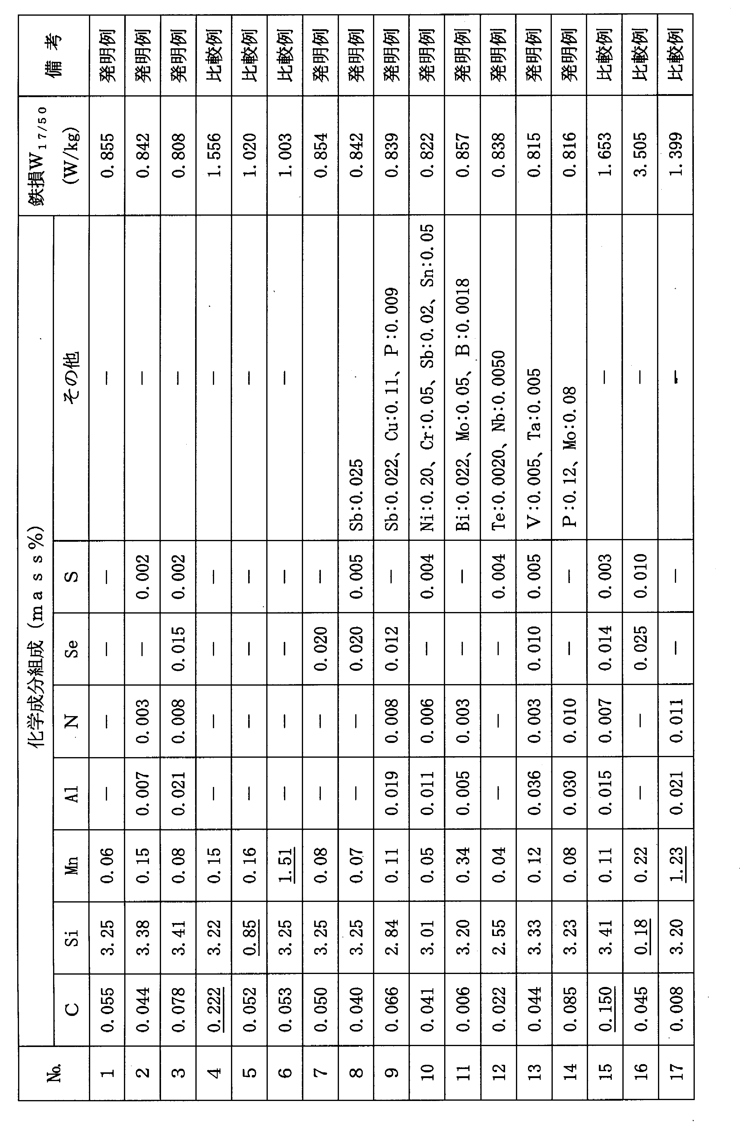
- a steel slab having the component composition shown in Table 2 and the balance being Fe and inevitable impurities is manufactured by a continuous casting method, heated to a temperature of 1380 ° C., and then hot-rolled to a thickness of 2.0 mm.
- a hot-rolled sheet was subjected to hot-rolled sheet annealing at 1030 ° C. for 10 seconds, and then cold-rolled to finish a cold-rolled sheet having a final sheet thickness of 0.23 mm. Thereafter, decarburization annealing was performed in a wet atmosphere of 50 vol% H 2 -50 vol% N 2 which also served as primary recrystallization annealing at 840 ° C. for 60 seconds. At this time, the temperature increase rate between 200 and 700 ° C.
- the technology of the present invention can also be applied to texture control of steel plates for automobiles.
Landscapes
- Chemical & Material Sciences (AREA)
- Engineering & Computer Science (AREA)
- Organic Chemistry (AREA)
- Materials Engineering (AREA)
- Mechanical Engineering (AREA)
- Metallurgy (AREA)
- Physics & Mathematics (AREA)
- Thermal Sciences (AREA)
- Crystallography & Structural Chemistry (AREA)
- Electromagnetism (AREA)
- Manufacturing & Machinery (AREA)
- Power Engineering (AREA)
- Dispersion Chemistry (AREA)
- Manufacturing Of Steel Electrode Plates (AREA)
- Soft Magnetic Materials (AREA)
Description
である。
<実験1>
C:0.065mass%、Si:3.44mass%、Mn:0.08mass%を含有する鋼を溶製し、連続鋳造法で鋼スラブとした後、1410℃に加熱し、熱間圧延して板厚2.4mmの熱延板とし、1050℃×60秒の熱延板焼鈍を施した後、一次冷間圧延して中間板厚の1.8mmとし、1120℃×80秒の中間焼鈍を施した後、200℃で温間圧延で最終板厚0.27mmの冷延板とした。
次いで、50vol%H2-50vol%N2の湿潤雰囲気下で840℃×80秒の一次再結晶焼鈍を兼ねた脱炭焼鈍を施した。なお、上記脱炭焼鈍は、840℃までの昇温過程における200~700℃間の昇温速度を100℃/sとし、さらにその昇温途中の450℃の温度で0~30秒間保定する処理を施した。ここで、上記100℃/sの昇温速度は、図1に示したように、200℃から700℃まで到達する時間から保定時間t2を除いたt1およびt3における平均昇温速度((700-200)/(t1+t3))のことをいう(以降、同様)。その後、MgOを主体とする焼鈍分離剤を鋼板表面に塗布し、乾燥した後、二次再結晶焼鈍と水素雰囲気下で1200℃×7時間の純化処理を含む仕上焼鈍を施した。
実験1で得られた最終板厚0.27mmの冷延板に、50vol%H2-50vol%N2の湿潤雰囲気下で、840℃×80秒の脱炭焼鈍を施した。なお、上記脱炭焼鈍における昇温速度は100℃/sとし、その昇温過程の200~700℃の温度範囲の任意の温度で1回、2秒間保定する処理を施した。その後、MgOを主体とする焼鈍分離剤を鋼板表面に塗布し、乾燥した後、二次再結晶焼鈍と水素雰囲気下で1200℃×7時間の純化処理を含む仕上焼鈍を施した。
急速加熱処理は、前述したように、再結晶集合組織における<111>//ND方位の発達を抑制する効果がある。一般的に、<111>//ND方位には、再結晶前の冷間圧延時に多くの歪が導入されるため、他の方位と比較して蓄積される歪エネルギーが高い状態にある。そのため、通常の昇温速度で加熱する脱炭焼鈍では、蓄積された歪エネルギーが高い<111>//ND方位の圧延組織から優先的に再結晶を起こす。再結晶によって、<111>//ND方位の圧延組織からは、<111>//ND方位粒が出現するため、<111>//ND方位が主方位となる。しかし、急速加熱を行うと、再結晶によって放出できるエネルギーよりも多くの熱エネルギーが付与されることから、比較的蓄積された歪エネルギーの低い方位でも再結晶が起こるようになるので、相対的に再結晶後の<111>//ND方位が減少する。これが、従来技術の急速加熱を行う理由である。
C:0.002~0.10mass%
Cは、0.002mass%に満たないと、Cによる粒界強化効果が失われ、スラブに割れが生じるなど、製造に支障を来たす欠陥を生ずるようになる。一方、0.10mass%を超えると、脱炭焼鈍で、磁気時効の起こらない0.005mass%以下に低減することが困難となる。よって、Cは0.002~0.10mass%の範囲とするのが好ましい。より好ましくは0.010~0.080mass%の範囲である。
Siは、鋼の比抵抗を高め、鉄損を低減すのに必要な元素である。上記効果は、2.0mass%未満では十分ではなく、一方、8.0mass%を超えると、加工性が低下し、圧延して製造すること困難となる。よって、Siは2.0~8.0mass%の範囲とするのが好ましい。より好ましくは2.5~4.5mass%の範囲である。
Mnは、鋼の熱間加工性を改善するために必要な元素である。上記効果は、0.005mass%未満では十分ではなく、一方、1.0mass%を超えると、製品板の磁束密度が低下するようになる。よって、Mnは0.005~1.0mass%の範囲とするのが好ましい。より好ましくは0.02~0.20mass%の範囲である。
まず、二次再結晶を生じさせるためにインヒビターを利用する場合で、例えば、AlN系インヒビターを利用するときには、AlおよびNを、それぞれAl:0.010~0.050mass%、N:0.003~0.020mass%の範囲で含有させるのが好ましい。また、MnS・MnSe系インヒビターを利用する場合には、前述した量のMnと、S:0.002~0.030mass%およびSe:0.003~0.030mass%のうちの1種または2種を含有させることが好ましい。それぞれ添加量が、上記下限値より少ないと、インヒビター効果が十分に得られず、一方、上限値を超えると、インヒビター成分がスラブ加熱時に未固溶で残存し、磁気特性の低下をもたらす。なお、AlN系とMnS・MnSe系のインヒビターは併用して用いてもよい。
前述した成分組成を有する鋼を常法の精錬プロセスで溶製した後、従来公知の造塊-分塊圧延法または連続鋳造法で鋼素材(スラブ)を製造してもよいし、あるいは、直接鋳造法で100mm以下の厚さの薄鋳片を製造してもよい。上記スラブは、常法に従い、例えば、インヒビター成分を含有する場合には、1400℃程度まで加熱し、一方、インヒビター成分を含まない場合は、1250℃以下の温度に加熱した後、熱間圧延に供する。なお、インヒビター成分を含有しない場合には、鋳造後、加熱することなく直ちに熱間圧延してもよい。また、薄鋳片の場合には、熱間圧延してもよいし、熱間圧延を省略してそのまま以後の工程に進めてもよい。
また、最終板厚とする冷間圧延(最終冷間圧延)は、冷間圧延時の鋼板温度を100℃~300℃に上昇させて行うことや、冷間圧延の途中で100~300℃の温度で時効処理を1回または複数回施すことが、一次再結晶集合組織を改善し、磁気特性を向上させるのに有効である。
ここで、上記200~700℃の区間における昇温速度(50℃/s以上)は、前述したように、保定する時間を除いた時間における昇温速度である。
また、250~600℃間での保定は、上記温度範囲のいずれかの温度で行えばよいが、上記温度は必ずしも一定でなくてもよく、10℃/s以下の低速昇温であれば、保定と同様の効果を得ることができるので、10℃/s以下の低速昇温としてもよい。
その後、50vol%H2-50vol%N2の湿潤雰囲気下で、840℃×100秒の脱炭焼鈍を施した。この際、850℃までの昇温過程における200~700℃間の昇温速度を表1に記載のごとく変化させるとともに、その昇温途中において、表1記載の温度および時間に保定する処理を施した。
次いで、MgOを主体とした焼鈍分離剤を鋼板表面に塗布、乾燥した後、さらに1200℃×10時間の純化処理を伴う仕上焼鈍を施した。仕上焼鈍の雰囲気は、純化処理する1200℃保定時はH2、昇温時および降温時はN2とした。

次いで、MgOを主体とした焼鈍分離剤を鋼板表面に塗布、乾燥した後、さらに1220℃×4時間の純化処理を伴う仕上焼鈍を施した。仕上焼鈍の雰囲気は、純化処理する1220℃保定時はH2、昇温時および降温時はArとした。
Claims (4)
- C:0.002~0.10mass%、Si:2.0~8.0mass%、Mn:0.005~1.0mass%を含有し、かつ、Al:0.010~0.050mass%およびN:0.003~0.020mass%を含有し、あるいは、Al:0.010~0.050mass%、N:0.003~0.020mass%、Se:0.003~0.030mass%および/またはS:0.002~0.03mass%を含有し、残部がFeおよび不可避的不純物からなる鋼素材を熱間圧延して熱延板とし、熱延板焼鈍を施した後もしくは施すことなく、1回または中間焼鈍を挟む2回以上の冷間圧延して最終板厚の冷延板とし、一次再結晶焼鈍を兼ねた脱炭焼鈍を施した後、鋼板表面に焼鈍分離剤を塗布し、仕上焼鈍する一連の工程からなる方向性電磁鋼板の製造方法において、
前記脱炭焼鈍の200~700℃の区間を50℃/s以上で急速加熱する際、250~600℃間のいずれかの温度で1~10秒間保定することを特徴とする方向性電磁鋼板の製造方法。 - C:0.002~0.10mass%、Si:2.0~8.0mass%、Mn:0.005~1.0mass%を含有し、かつ、Se:0.003~0.030mass%およびS:0.002~0.03mass%のうちから選ばれる1種または2種を含有し、残部がFeおよび不可避的不純物からなる鋼素材を熱間圧延して熱延板とし、熱延板焼鈍を施した後もしくは施すことなく、1回または中間焼鈍を挟む2回以上の冷間圧延して最終板厚の冷延板とし、一次再結晶焼鈍を兼ねた脱炭焼鈍を施した後、鋼板表面に焼鈍分離剤を塗布し、仕上焼鈍する一連の工程からなる方向性電磁鋼板の製造方法において、
前記脱炭焼鈍の200~700℃の区間を50℃/s以上で急速加熱する際、250~600℃間のいずれかの温度で1~10秒間保定することを特徴とする方向性電磁鋼板の製造方法。 - C:0.002~0.10mass%、Si:2.0~8.0mass%、Mn:0.005~1.0mass%を含有し、かつ、Al:0.01mass%未満、N:0.0050mass%未満、Se:0.0030mass%未満およびS:0.0050mass%未満に低減してなり、残部がFeおよび不可避的不純物からなる鋼素材を熱間圧延して熱延板とし、熱延板焼鈍を施した後もしくは施すことなく、1回または中間焼鈍を挟む2回以上の冷間圧延して最終板厚の冷延板とし、一次再結晶焼鈍を兼ねた脱炭焼鈍を施した後、鋼板表面に焼鈍分離剤を塗布し、仕上焼鈍する一連の工程からなる方向性電磁鋼板の製造方法において、
前記脱炭焼鈍の200~700℃の区間を50℃/s以上で急速加熱する際、250~600℃間のいずれかの温度で1~10秒間保定することを特徴とする方向性電磁鋼板の製造方法。 - 前記鋼素材は、前記成分組成に加えてさらに、Ni:0.010~1.50mass%、Cr:0.01~0.50mass%、Cu:0.01~0.50mass%、P:0.005~0.50mass%、Sb:0.005~0.50mass%、Sn;0.005~0.50mass%、Bi:0.005~0.50mass%、Mo:0.005~0.100mass%、B:0.0002~0.0025mass%、Te:0.0005~0.0100mass%、Nb:0.0010~0.0100mass%、V:0.001~0.010mass%およびTa:0.001~0.010mass%のうちから選ばれる1種または2種以上を含有することを特徴とする請求項1~3のいずれか1項に記載の方向性電磁鋼板の製造方法。
Priority Applications (7)
| Application Number | Priority Date | Filing Date | Title |
|---|---|---|---|
| CN201380038008.0A CN104471085A (zh) | 2012-07-26 | 2013-07-25 | 取向性电磁钢板的制造方法 |
| US14/415,089 US9617616B2 (en) | 2012-07-26 | 2013-07-25 | Method for producing grain-oriented electrical steel sheet |
| IN613DEN2015 IN2015DN00613A (ja) | 2012-07-26 | 2013-07-25 | |
| KR1020147035233A KR101558292B1 (ko) | 2012-07-26 | 2013-07-25 | 방향성 전자 강판의 제조 방법 |
| RU2015104182/02A RU2595190C1 (ru) | 2012-07-26 | 2013-07-25 | Способ изготовления листа электротехнической текстурированной стали |
| EP13822382.1A EP2878687B1 (en) | 2012-07-26 | 2013-07-25 | Method for producing grain-oriented electrical steel sheet |
| US15/208,720 US9738949B2 (en) | 2012-07-26 | 2016-07-13 | Method for producing grain-oriented electrical steel sheet |
Applications Claiming Priority (2)
| Application Number | Priority Date | Filing Date | Title |
|---|---|---|---|
| JP2012-165516 | 2012-07-26 | ||
| JP2012165516A JP5672273B2 (ja) | 2012-07-26 | 2012-07-26 | 方向性電磁鋼板の製造方法 |
Related Child Applications (2)
| Application Number | Title | Priority Date | Filing Date |
|---|---|---|---|
| US14/415,089 A-371-Of-International US9617616B2 (en) | 2012-07-26 | 2013-07-25 | Method for producing grain-oriented electrical steel sheet |
| US15/208,720 Division US9738949B2 (en) | 2012-07-26 | 2016-07-13 | Method for producing grain-oriented electrical steel sheet |
Publications (1)
| Publication Number | Publication Date |
|---|---|
| WO2014017589A1 true WO2014017589A1 (ja) | 2014-01-30 |
Family
ID=49997398
Family Applications (1)
| Application Number | Title | Priority Date | Filing Date |
|---|---|---|---|
| PCT/JP2013/070185 Ceased WO2014017589A1 (ja) | 2012-07-26 | 2013-07-25 | 方向性電磁鋼板の製造方法 |
Country Status (8)
| Country | Link |
|---|---|
| US (2) | US9617616B2 (ja) |
| EP (1) | EP2878687B1 (ja) |
| JP (1) | JP5672273B2 (ja) |
| KR (1) | KR101558292B1 (ja) |
| CN (3) | CN104471085A (ja) |
| IN (1) | IN2015DN00613A (ja) |
| RU (1) | RU2595190C1 (ja) |
| WO (1) | WO2014017589A1 (ja) |
Cited By (6)
| Publication number | Priority date | Publication date | Assignee | Title |
|---|---|---|---|---|
| WO2014126089A1 (ja) * | 2013-02-14 | 2014-08-21 | Jfeスチール株式会社 | 方向性電磁鋼板の製造方法 |
| WO2014132930A1 (ja) * | 2013-02-28 | 2014-09-04 | Jfeスチール株式会社 | 方向性電磁鋼板の製造方法 |
| JP2015183189A (ja) * | 2014-03-20 | 2015-10-22 | Jfeスチール株式会社 | 方向性電磁鋼板とその製造方法 |
| JP2015193921A (ja) * | 2014-03-17 | 2015-11-05 | Jfeスチール株式会社 | 鉄損特性に優れる方向性電磁鋼板の製造方法 |
| CN106414780A (zh) * | 2014-05-12 | 2017-02-15 | 杰富意钢铁株式会社 | 取向性电磁钢板的制造方法 |
| EP3214188A4 (en) * | 2014-10-30 | 2017-09-06 | JFE Steel Corporation | Production method for oriented grain-electromagnetic steel sheet |
Families Citing this family (34)
| Publication number | Priority date | Publication date | Assignee | Title |
|---|---|---|---|---|
| JP5716870B2 (ja) | 2012-07-26 | 2015-05-13 | Jfeスチール株式会社 | 方向性電磁鋼板の製造方法 |
| JP5672273B2 (ja) | 2012-07-26 | 2015-02-18 | Jfeスチール株式会社 | 方向性電磁鋼板の製造方法 |
| KR101707539B1 (ko) | 2012-07-26 | 2017-02-16 | 제이에프이 스틸 가부시키가이샤 | 방향성 전자 강판의 제조 방법 |
| JP6137490B2 (ja) * | 2014-03-28 | 2017-05-31 | Jfeスチール株式会社 | 一次再結晶集合組織の予測方法および方向性電磁鋼板の製造方法 |
| JP6143010B2 (ja) * | 2014-04-04 | 2017-06-07 | Jfeスチール株式会社 | 鉄損特性に優れる方向性電磁鋼板の製造方法 |
| CN104372238B (zh) * | 2014-09-28 | 2016-05-11 | 东北大学 | 一种取向高硅钢的制备方法 |
| CN104294155B (zh) * | 2014-09-28 | 2016-05-11 | 东北大学 | 一种超低碳取向硅钢及其制备方法 |
| US20170298467A1 (en) * | 2014-10-06 | 2017-10-19 | Jfe Steel Corporation | Low iron loss grain oriented electrical steel sheet and method for manufacturing the same |
| JP6354957B2 (ja) | 2015-07-08 | 2018-07-11 | Jfeスチール株式会社 | 方向性電磁鋼板とその製造方法 |
| JP6572855B2 (ja) * | 2016-09-21 | 2019-09-11 | Jfeスチール株式会社 | 方向性電磁鋼板およびその製造方法 |
| JP6631725B2 (ja) * | 2016-11-01 | 2020-01-15 | Jfeスチール株式会社 | 方向性電磁鋼板の製造方法 |
| KR102295735B1 (ko) * | 2017-02-20 | 2021-08-30 | 제이에프이 스틸 가부시키가이샤 | 방향성 전기 강판의 제조 방법 |
| RU2661967C1 (ru) * | 2017-04-10 | 2018-07-23 | Публичное Акционерное Общество "Новолипецкий металлургический комбинат" | Способ производства электротехнической анизотропной стали с высокими характеристиками адгезии и коэффициента сопротивления электроизоляционного покрытия |
| US11145446B2 (en) | 2017-07-13 | 2021-10-12 | Nippon Steel Corporation | Grain-oriented electrical steel sheet |
| US11459633B2 (en) * | 2017-12-28 | 2022-10-04 | Jfe Steel Corporation | Low-iron-loss grain-oriented electrical steel sheet and production method for same |
| JP7063032B2 (ja) * | 2018-03-20 | 2022-05-09 | 日本製鉄株式会社 | 方向性電磁鋼板の製造方法 |
| BR112020018664B1 (pt) * | 2018-03-22 | 2024-04-30 | Nippon Steel Corporation | Chapa de aço elétrica com grão orientado e método para produzir a chapa de aço elétrica com grão orientado |
| EP3854892B1 (en) | 2018-09-27 | 2024-06-05 | JFE Steel Corporation | Grain-oriented electrical steel sheet and method for producing same |
| RU2769149C1 (ru) | 2018-09-28 | 2022-03-28 | ДжФЕ СТИЛ КОРПОРЕЙШН | Способ изготовления листа из текстурированной электротехнической стали и стан холодной прокатки |
| KR102142511B1 (ko) * | 2018-11-30 | 2020-08-07 | 주식회사 포스코 | 방향성 전기강판 및 그의 제조방법 |
| JP6888603B2 (ja) * | 2018-11-30 | 2021-06-16 | Jfeスチール株式会社 | 方向性電磁鋼板の製造方法 |
| KR102583079B1 (ko) * | 2019-01-16 | 2023-10-04 | 닛폰세이테츠 가부시키가이샤 | 방향성 전자 강판의 제조 방법 |
| KR102579761B1 (ko) | 2019-01-16 | 2023-09-19 | 닛폰세이테츠 가부시키가이샤 | 방향성 전자 강판의 제조 방법 |
| PL3913100T3 (pl) | 2019-01-16 | 2024-01-29 | Nippon Steel Corporation | Blacha cienka ze stali elektrotechnicznej o ziarnach zorientowanych |
| CN111485166A (zh) * | 2019-01-29 | 2020-08-04 | 宝山钢铁股份有限公司 | 一种冷轧耐低温酸露点腐蚀钢及其制造方法 |
| JP7006851B1 (ja) * | 2020-05-19 | 2022-02-10 | Jfeスチール株式会社 | 方向性電磁鋼板およびその製造方法 |
| EP4174194A4 (en) * | 2020-06-24 | 2024-07-03 | Nippon Steel Corporation | METHOD FOR PRODUCING A GRAIN-ORIENTED ELECTRICAL STEEL SHEET |
| JP7107454B1 (ja) * | 2020-09-01 | 2022-07-27 | Jfeスチール株式会社 | 方向性電磁鋼板の製造方法 |
| CN112159935B (zh) * | 2020-09-30 | 2021-11-09 | 武汉钢铁有限公司 | 一种具有低噪声特性的高磁感取向硅钢及生产方法 |
| JP7392848B2 (ja) * | 2021-02-04 | 2023-12-06 | Jfeスチール株式会社 | 方向性電磁鋼板の製造方法およびそれに用いる焼鈍分離剤 |
| US20240150875A1 (en) * | 2021-03-31 | 2024-05-09 | Jfe Steel Corporation | Method for producing grain-oriented electrical steel sheet |
| CN117355622A (zh) * | 2021-05-28 | 2024-01-05 | 杰富意钢铁株式会社 | 取向性电磁钢板的制造方法 |
| CN117545862A (zh) * | 2021-06-30 | 2024-02-09 | 杰富意钢铁株式会社 | 取向性电磁钢板的制造方法及取向性电磁钢板制造用轧制设备 |
| CN118127288B (zh) * | 2024-01-30 | 2026-04-07 | 武汉钢铁有限公司 | 快速加热常化制备低温高磁感取向硅钢的方法 |
Citations (7)
| Publication number | Priority date | Publication date | Assignee | Title |
|---|---|---|---|---|
| JPS63105926A (ja) * | 1986-10-23 | 1988-05-11 | Kawasaki Steel Corp | 一方向性けい素鋼板の製造方法 |
| JPH0762436A (ja) | 1993-08-24 | 1995-03-07 | Nippon Steel Corp | 極めて低い鉄損をもつ一方向性電磁鋼板の製造方法 |
| JPH10130729A (ja) | 1996-10-31 | 1998-05-19 | Nippon Steel Corp | 極めて低い鉄損をもつ一方向性電磁鋼板の製造方法 |
| JPH10298653A (ja) | 1997-04-25 | 1998-11-10 | Nippon Steel Corp | 極めて低い鉄損をもつ一方向性電磁鋼板の製造方法 |
| JP2003027194A (ja) | 2001-07-12 | 2003-01-29 | Nippon Steel Corp | 皮膜特性と磁気特性に優れた方向性電磁鋼板およびその製造方法 |
| JP2008001983A (ja) * | 2006-05-24 | 2008-01-10 | Nippon Steel Corp | 磁束密度の高い方向性電磁鋼板の製造方法 |
| JP2013047383A (ja) * | 2011-07-28 | 2013-03-07 | Jfe Steel Corp | 極薄方向性電磁鋼板の製造方法 |
Family Cites Families (18)
| Publication number | Priority date | Publication date | Assignee | Title |
|---|---|---|---|---|
| US4975127A (en) * | 1987-05-11 | 1990-12-04 | Kawasaki Steel Corp. | Method of producing grain oriented silicon steel sheets having magnetic properties |
| US4898626A (en) | 1988-03-25 | 1990-02-06 | Armco Advanced Materials Corporation | Ultra-rapid heat treatment of grain oriented electrical steel |
| JP2983129B2 (ja) | 1993-08-24 | 1999-11-29 | 新日本製鐵株式会社 | 極めて低い鉄損をもつ一方向性電磁鋼板の製造方法 |
| JPH07312306A (ja) | 1994-05-18 | 1995-11-28 | Rohm Co Ltd | チップ抵抗器における端子電極膜の塗布装置 |
| JP3011609B2 (ja) | 1994-05-18 | 2000-02-21 | 新日本製鐵株式会社 | 磁気特性の優れたグラス被膜の少ない一方向性電磁鋼板の製造方法 |
| KR100293141B1 (ko) * | 1997-04-16 | 2001-06-15 | 아사무라 타카싯 | 피막특성과 자기특성이 우수한 일방향성 전자강판과 그 제조방법및그제조방법에사용되는탈탄소둔설비 |
| JP3537339B2 (ja) | 1999-01-14 | 2004-06-14 | 新日本製鐵株式会社 | 皮膜特性と磁気特性に優れた方向性電磁鋼板及びその製造方法 |
| JP2000256810A (ja) * | 1999-03-11 | 2000-09-19 | Kawasaki Steel Corp | 低磁場高周波での磁気特性及び打ち抜き加工性に優れる方向性けい素鋼板及びその製造方法 |
| JP4823719B2 (ja) * | 2006-03-07 | 2011-11-24 | 新日本製鐵株式会社 | 磁気特性が極めて優れた方向性電磁鋼板の製造方法 |
| BRPI0712010B1 (pt) | 2006-05-24 | 2014-10-29 | Nippon Steel & Sumitomo Metal Corp | Métodos de produção de uma chapa de aço elétrico com grãos orientados |
| JP2008001979A (ja) | 2006-05-24 | 2008-01-10 | Nippon Steel Corp | 方向性電磁鋼板の製造方法とその製造方法に用いる脱炭焼鈍炉 |
| KR101165430B1 (ko) * | 2006-11-22 | 2012-07-12 | 신닛뽄세이테쯔 카부시키카이샤 | 피막 밀착성이 우수한 일방향성 전자 강판 및 그 제조법 |
| JP4833906B2 (ja) * | 2007-04-20 | 2011-12-07 | 新日本製鐵株式会社 | 誘導加熱設備 |
| WO2010047414A1 (ja) * | 2008-10-22 | 2010-04-29 | Jfeスチール株式会社 | 方向性電磁鋼板の製造方法 |
| JP2010163634A (ja) | 2009-01-13 | 2010-07-29 | Chugai Ro Co Ltd | ストリップ材処理装置 |
| JP5991484B2 (ja) | 2011-12-06 | 2016-09-14 | Jfeスチール株式会社 | 低鉄損方向性電磁鋼板の製造方法 |
| JP5672273B2 (ja) | 2012-07-26 | 2015-02-18 | Jfeスチール株式会社 | 方向性電磁鋼板の製造方法 |
| KR101707539B1 (ko) | 2012-07-26 | 2017-02-16 | 제이에프이 스틸 가부시키가이샤 | 방향성 전자 강판의 제조 방법 |
-
2012
- 2012-07-26 JP JP2012165516A patent/JP5672273B2/ja active Active
-
2013
- 2013-07-25 KR KR1020147035233A patent/KR101558292B1/ko active Active
- 2013-07-25 US US14/415,089 patent/US9617616B2/en active Active
- 2013-07-25 CN CN201380038008.0A patent/CN104471085A/zh active Pending
- 2013-07-25 CN CN201810218151.2A patent/CN108359896A/zh active Pending
- 2013-07-25 IN IN613DEN2015 patent/IN2015DN00613A/en unknown
- 2013-07-25 EP EP13822382.1A patent/EP2878687B1/en active Active
- 2013-07-25 WO PCT/JP2013/070185 patent/WO2014017589A1/ja not_active Ceased
- 2013-07-25 RU RU2015104182/02A patent/RU2595190C1/ru active
- 2013-07-25 CN CN201810219246.6A patent/CN108486342A/zh active Pending
-
2016
- 2016-07-13 US US15/208,720 patent/US9738949B2/en active Active
Patent Citations (7)
| Publication number | Priority date | Publication date | Assignee | Title |
|---|---|---|---|---|
| JPS63105926A (ja) * | 1986-10-23 | 1988-05-11 | Kawasaki Steel Corp | 一方向性けい素鋼板の製造方法 |
| JPH0762436A (ja) | 1993-08-24 | 1995-03-07 | Nippon Steel Corp | 極めて低い鉄損をもつ一方向性電磁鋼板の製造方法 |
| JPH10130729A (ja) | 1996-10-31 | 1998-05-19 | Nippon Steel Corp | 極めて低い鉄損をもつ一方向性電磁鋼板の製造方法 |
| JPH10298653A (ja) | 1997-04-25 | 1998-11-10 | Nippon Steel Corp | 極めて低い鉄損をもつ一方向性電磁鋼板の製造方法 |
| JP2003027194A (ja) | 2001-07-12 | 2003-01-29 | Nippon Steel Corp | 皮膜特性と磁気特性に優れた方向性電磁鋼板およびその製造方法 |
| JP2008001983A (ja) * | 2006-05-24 | 2008-01-10 | Nippon Steel Corp | 磁束密度の高い方向性電磁鋼板の製造方法 |
| JP2013047383A (ja) * | 2011-07-28 | 2013-03-07 | Jfe Steel Corp | 極薄方向性電磁鋼板の製造方法 |
Cited By (11)
| Publication number | Priority date | Publication date | Assignee | Title |
|---|---|---|---|---|
| WO2014126089A1 (ja) * | 2013-02-14 | 2014-08-21 | Jfeスチール株式会社 | 方向性電磁鋼板の製造方法 |
| US10192662B2 (en) | 2013-02-14 | 2019-01-29 | Jfe Steel Corporation | Method for producing grain-oriented electrical steel sheet |
| WO2014132930A1 (ja) * | 2013-02-28 | 2014-09-04 | Jfeスチール株式会社 | 方向性電磁鋼板の製造方法 |
| JP5737483B2 (ja) * | 2013-02-28 | 2015-06-17 | Jfeスチール株式会社 | 方向性電磁鋼板の製造方法 |
| US10134514B2 (en) | 2013-02-28 | 2018-11-20 | Jfe Steel Corporation | Method for producing grain-oriented electrical steel sheet |
| JP2015193921A (ja) * | 2014-03-17 | 2015-11-05 | Jfeスチール株式会社 | 鉄損特性に優れる方向性電磁鋼板の製造方法 |
| JP2015183189A (ja) * | 2014-03-20 | 2015-10-22 | Jfeスチール株式会社 | 方向性電磁鋼板とその製造方法 |
| CN106414780A (zh) * | 2014-05-12 | 2017-02-15 | 杰富意钢铁株式会社 | 取向性电磁钢板的制造方法 |
| EP3144400A4 (en) * | 2014-05-12 | 2017-05-17 | JFE Steel Corporation | Method for producing oriented electromagnetic steel sheet |
| US10294543B2 (en) | 2014-05-12 | 2019-05-21 | Jfe Steel Corporation | Method for producing grain-oriented electrical steel sheet |
| EP3214188A4 (en) * | 2014-10-30 | 2017-09-06 | JFE Steel Corporation | Production method for oriented grain-electromagnetic steel sheet |
Also Published As
| Publication number | Publication date |
|---|---|
| EP2878687A4 (en) | 2016-03-16 |
| RU2595190C1 (ru) | 2016-08-20 |
| US9738949B2 (en) | 2017-08-22 |
| US9617616B2 (en) | 2017-04-11 |
| KR20150010786A (ko) | 2015-01-28 |
| EP2878687B1 (en) | 2017-12-13 |
| US20150187473A1 (en) | 2015-07-02 |
| CN108359896A (zh) | 2018-08-03 |
| JP5672273B2 (ja) | 2015-02-18 |
| CN108486342A (zh) | 2018-09-04 |
| JP2014025106A (ja) | 2014-02-06 |
| IN2015DN00613A (ja) | 2015-06-26 |
| EP2878687A1 (en) | 2015-06-03 |
| KR101558292B1 (ko) | 2015-10-07 |
| CN104471085A (zh) | 2015-03-25 |
| US20160319390A1 (en) | 2016-11-03 |
Similar Documents
| Publication | Publication Date | Title |
|---|---|---|
| JP5672273B2 (ja) | 方向性電磁鋼板の製造方法 | |
| JP5737483B2 (ja) | 方向性電磁鋼板の製造方法 | |
| JP5854233B2 (ja) | 方向性電磁鋼板の製造方法 | |
| JP6119959B2 (ja) | 方向性電磁鋼板の製造方法 | |
| WO2016067636A1 (ja) | 方向性電磁鋼板の製造方法 | |
| JP5871137B2 (ja) | 方向性電磁鋼板 | |
| JP6004183B2 (ja) | 方向性電磁鋼板の製造方法 | |
| JP5839204B2 (ja) | 方向性電磁鋼板の製造方法 | |
| JP6206633B2 (ja) | 方向性電磁鋼板の製造方法 | |
| JP5888525B2 (ja) | 方向性電磁鋼板の製造方法 | |
| JP5754115B2 (ja) | 方向性電磁鋼板およびその製造方法 | |
| JP5854236B2 (ja) | 方向性電磁鋼板の製造方法 | |
| JP5846390B2 (ja) | 方向性電磁鋼板の製造方法 | |
| JP6143010B2 (ja) | 鉄損特性に優れる方向性電磁鋼板の製造方法 | |
| JP5310510B2 (ja) | 方向性電磁鋼板の製造方法 | |
| JP6544344B2 (ja) | 方向性電磁鋼板の製造方法 | |
| JP2016084540A (ja) | 方向性電磁鋼板の製造方法 |
Legal Events
| Date | Code | Title | Description |
|---|---|---|---|
| 121 | Ep: the epo has been informed by wipo that ep was designated in this application |
Ref document number: 13822382 Country of ref document: EP Kind code of ref document: A1 |
|
| ENP | Entry into the national phase |
Ref document number: 20147035233 Country of ref document: KR Kind code of ref document: A |
|
| WWE | Wipo information: entry into national phase |
Ref document number: 14415089 Country of ref document: US |
|
| WWE | Wipo information: entry into national phase |
Ref document number: 2013822382 Country of ref document: EP |
|
| NENP | Non-entry into the national phase |
Ref country code: DE |
|
| ENP | Entry into the national phase |
Ref document number: 2015104182 Country of ref document: RU Kind code of ref document: A |