WO2014019283A1 - 传输控制信息的方法、装置及系统 - Google Patents
传输控制信息的方法、装置及系统 Download PDFInfo
- Publication number
- WO2014019283A1 WO2014019283A1 PCT/CN2012/082147 CN2012082147W WO2014019283A1 WO 2014019283 A1 WO2014019283 A1 WO 2014019283A1 CN 2012082147 W CN2012082147 W CN 2012082147W WO 2014019283 A1 WO2014019283 A1 WO 2014019283A1
- Authority
- WO
- WIPO (PCT)
- Prior art keywords
- enhanced
- resource
- resource unit
- resource block
- unit
- Prior art date
- Legal status (The legal status is an assumption and is not a legal conclusion. Google has not performed a legal analysis and makes no representation as to the accuracy of the status listed.)
- Ceased
Links
Classifications
-
- H—ELECTRICITY
- H04—ELECTRIC COMMUNICATION TECHNIQUE
- H04L—TRANSMISSION OF DIGITAL INFORMATION, e.g. TELEGRAPHIC COMMUNICATION
- H04L1/00—Arrangements for detecting or preventing errors in the information received
- H04L1/004—Arrangements for detecting or preventing errors in the information received by using forward error control
- H04L1/0056—Systems characterized by the type of code used
- H04L1/0071—Use of interleaving
-
- H—ELECTRICITY
- H04—ELECTRIC COMMUNICATION TECHNIQUE
- H04L—TRANSMISSION OF DIGITAL INFORMATION, e.g. TELEGRAPHIC COMMUNICATION
- H04L5/00—Arrangements affording multiple use of the transmission path
- H04L5/003—Arrangements for allocating sub-channels of the transmission path
-
- H—ELECTRICITY
- H04—ELECTRIC COMMUNICATION TECHNIQUE
- H04L—TRANSMISSION OF DIGITAL INFORMATION, e.g. TELEGRAPHIC COMMUNICATION
- H04L5/00—Arrangements affording multiple use of the transmission path
- H04L5/0001—Arrangements for dividing the transmission path
- H04L5/0003—Two-dimensional division
- H04L5/0005—Time-frequency
- H04L5/0007—Time-frequency the frequencies being orthogonal, e.g. OFDM(A) or DMT
-
- H—ELECTRICITY
- H04—ELECTRIC COMMUNICATION TECHNIQUE
- H04L—TRANSMISSION OF DIGITAL INFORMATION, e.g. TELEGRAPHIC COMMUNICATION
- H04L27/00—Modulated-carrier systems
- H04L27/26—Systems using multi-frequency codes
- H04L27/2601—Multicarrier modulation systems
-
- H04L27/2611—
-
- H—ELECTRICITY
- H04—ELECTRIC COMMUNICATION TECHNIQUE
- H04L—TRANSMISSION OF DIGITAL INFORMATION, e.g. TELEGRAPHIC COMMUNICATION
- H04L5/00—Arrangements affording multiple use of the transmission path
- H04L5/003—Arrangements for allocating sub-channels of the transmission path
- H04L5/0044—Allocation of payload; Allocation of data channels, e.g. PDSCH or PUSCH
- H04L5/0046—Determination of the number of bits transmitted on different sub-channels
-
- H—ELECTRICITY
- H04—ELECTRIC COMMUNICATION TECHNIQUE
- H04L—TRANSMISSION OF DIGITAL INFORMATION, e.g. TELEGRAPHIC COMMUNICATION
- H04L5/00—Arrangements affording multiple use of the transmission path
- H04L5/003—Arrangements for allocating sub-channels of the transmission path
- H04L5/0048—Allocation of pilot signals, i.e. of signals known to the receiver
-
- H—ELECTRICITY
- H04—ELECTRIC COMMUNICATION TECHNIQUE
- H04L—TRANSMISSION OF DIGITAL INFORMATION, e.g. TELEGRAPHIC COMMUNICATION
- H04L5/00—Arrangements affording multiple use of the transmission path
- H04L5/003—Arrangements for allocating sub-channels of the transmission path
- H04L5/0053—Allocation of signalling, i.e. of overhead other than pilot signals
-
- H—ELECTRICITY
- H04—ELECTRIC COMMUNICATION TECHNIQUE
- H04W—WIRELESS COMMUNICATION NETWORKS
- H04W72/00—Local resource management
- H04W72/20—Control channels or signalling for resource management
- H04W72/23—Control channels or signalling for resource management in the downlink direction of a wireless link, i.e. towards a terminal
Definitions
- the present invention relates to the field of wireless communication technologies, and in particular, to a method, device, and system for transmitting control information.
- 0FDMA Frequency Division Multiplexing Access
- LTE/LTE-A Long Term Evolution/High Speed Packet Access
- a major feature of the technology is that an RB (resource block) can be composed of multiple REs (resource units), and each RE constituting an RB can bear different information, for example: as shown in FIG.
- REs in one RB may be allocated as follows: information in the PDCCH channel, and reference signals (CRS) at the cell level, reference signals at the user level, channel state information reference signals (CSI-RS), and the like.
- the reference signal can be mapped to the RE of the black portion of the RB shown in FIG.
- the RE of the white portion of the RB shown in FIG. 1a bears information of a control channel such as a PDSCH or an ePDCCH, such as control information such as DCI.
- control information transmitted by the ePDCCH is mapped to a series of RBs by using the eREG as a basic resource unit, and the information processed by the base station and the like in the wireless communication system is presented by the eCCE.
- an eCCE is composed of multiple eREGs, and the group Multiple eREGs into one eCCE are from multiple RBs in this series of RBs.
- the unlabeled part is the corresponding RE of the eREG in the RB.
- eREG 0 is composed of the RE numbered 0 in the unlabeled part.
- the number of REs corresponding to eREG 0-7 is 16, 12, 15, 14, 12, 13, 12, 14, that is, the size of each eREG is different.
- the size of the largest eREG is 16 REs
- the size of the smallest eREG is 12 REs, which differs by 4 REs.
- an eCCE is composed of a plurality of eREGs corresponding to the plurality of RBs.
- eREG 0 in RB0 and eREG 0 in RBI form an eCCE
- eREG 1 in RB0 and eREG 1 in RB1 form another eCCE
- multiple eCCEs can be obtained in the end, such as the eight eCCEs numbered eCCE a0_a7.
- the two eREGs of the composed eCCE may have poor channel frequency diversity during transmission, and the frequency diversity is poor. Resulting in the loss of processing information of the terminal device, for example: the error rate or the block error rate of the control information sent by the base station received by the terminal device is high, thereby reducing the 'li energy of the communication system, for example: when information loss is found Next, the base station needs to resend the information to further communicate the performance of the system.
- Embodiments of the present invention provide a method, apparatus, and system for transmitting control information, which enable Before transmitting the control information, the base station interleaves the eREG or groups the RBs, and configures the eCEs of the same e CCE into the non-adjacent RBs, thereby reducing the problem of poor channel frequency diversity and reducing the terminal.
- the probability of loss of information of the device improves the performance of the communication system.
- an embodiment of the present invention provides a method for transmitting control information, including: determining an enhanced resource unit group eREG number in a resource block RB, and determining an enhanced resource unit according to the enhanced resource unit group number in the resource block RB. The location of the corresponding resource unit;
- Corresponding control information is transmitted at a location of the corresponding control unit of the control channel unit.
- the interleaving the enhanced resource unit group includes:
- the number of rows or columns of the interleaver being the number of enhanced resource unit groups or multiples of the number of resource blocks included in the acquired resource block
- the number of rows or columns of the interleaver is one of presets 4, 8, 1, 2, 16 or 32. According to the interleaver, the enhanced resource unit group numbers in the resource blocks are interleaved.
- an embodiment of the present invention provides a method for transmitting control information, including: Determining an enhanced resource unit group e REG in the resource block RB;
- the grouping the resource blocks includes:
- the physical resource block number N corresponding to the even time slot and the odd time slot and the physical resource block number M corresponding to the even time slot and the odd time slot are divided into the same group.
- an embodiment of the present invention provides a method for transmitting control information, including: determining an enhanced resource unit group eREG number in a resource block RB, and determining an enhanced resource according to the enhanced resource unit group number in the resource block RB.
- the unit group corresponds to the location of the resource unit;
- the embodiment of the present invention provides a method for transmitting control information, including: determining an enhanced resource unit group eREG number in a resource block RB, and determining an enhanced resource unit group corresponding according to the enhanced resource unit group number. The location of the resource unit;
- the enhanced control channel unit corresponds to the control information transmitted by the location of the resource unit.
- an embodiment of the present invention provides a base station device, including:
- a first configuration module configured to determine an enhanced resource unit group eREG number in the resource block RB, and determine, according to the enhanced resource unit group number in the resource block R B, an enhanced resource unit group corresponding resource unit location;
- An interleaving module configured to interleave the enhanced resource unit group number, and determine an enhanced control channel unit e C C E according to the at least two enhanced resource unit groups after the interleaving;
- a first mapping module determining, according to the location of the enhanced control channel unit and the enhanced resource unit group corresponding to the resource unit, a location of the corresponding resource unit corresponding to the enhanced control channel unit;
- a first transmission module configured to transmit corresponding control information at a location of the resource unit corresponding to the control channel unit.
- an embodiment of the present invention provides a base station device, including: a second configuration module, configured to determine an enhanced resource unit group eREG in the resource block RB;
- a resource block grouping module configured to group the resource blocks
- a second mapping module configured to map control information to the enhanced resource unit group in the resource block after the grouping
- the second transmission module is configured to transmit the mapped control information.
- an embodiment of the present invention provides a terminal device, including:
- a first location determining module configured to determine an enhanced resource unit group eREG number in the resource block RB, and determine, according to the enhanced resource unit group number in the resource block R B, a location of the enhanced resource unit group corresponding to the resource unit;
- a first determining module an interleaver for determining the enhanced resource unit group number, determining, according to the interleaver, at least two enhanced resource unit groups corresponding to the enhanced control channel unit; according to the enhanced control
- the channel unit and the enhanced resource unit group correspond to the location of the resource unit, and determine the location of the corresponding resource unit corresponding to the enhanced control channel unit;
- a first receiving module configured to receive control information that is sent by the base station at a location of the corresponding resource unit of the enhanced control channel unit;
- an embodiment of the present invention provides a terminal device, including:
- a second determining module configured to determine an enhanced resource unit group eREG number in the resource block RB, and determine, according to the enhanced resource unit group number, a location of the corresponding resource unit group corresponding to the resource unit; a third determining module, configured to acquire a grouping situation of the resource block by the base station, where the second mapping module is configured to: according to the grouping of the resource block by the base station and the location of the resource element corresponding to the enhanced resource unit group, And determining, by the second receiving module, the control information that is sent by the base station in the location of the corresponding resource unit of the enhanced control channel unit in the resource block group.
- the method, device, and system for transmitting control information provided by the embodiment of the present invention enable the base station to interleave the eREG or group the RBs before transmitting the control information, and configure the eREGs of the same e CCE to be non-adjacent.
- the problem of poor channel frequency diversity is mitigated, thereby reducing the probability of loss of information of the terminal device and improving the performance of the communication system.
- FIG. 1 is a schematic structural diagram of a resource block in the prior art
- FIG. 2a is a flowchart of a method for transmitting control information according to Embodiment 1 of the present invention
- FIG. 2b is a flowchart provided by Embodiment 1 of the present invention
- FIG. 2 is a schematic structural diagram of another resource block according to Embodiment 1 of the present invention
- FIG. 3 a is a flowchart of a method for transmitting control information according to Embodiment 2 of the present invention
- FIG. 3b is a flowchart of another method for transmitting control information according to Embodiment 2 of the present invention
- FIG. 3 is a flowchart of still another method for transmitting control information according to Embodiment 2 of the present invention
- FIG. 4 is a flowchart of a method for transmitting control information according to Embodiment 3 of the present invention
- FIG. 4 b is another flowchart provided by Embodiment 3 of the present invention
- FIG. 4 is a flowchart of still another method for transmitting control information according to Embodiment 3 of the present invention
- FIG. 5 is still another transmission control information according to Embodiment 4 of the present invention
- FIG. 6 is a flowchart of a method for transmitting a control message according to Embodiment 5 of the present invention
- FIG. 8 is a flowchart of a method for transmitting control information according to Embodiment 7 of the present invention
- FIG. 8 is a flowchart of another method for transmitting control information according to Embodiment 7 of the present invention
- FIG. 9 is a flowchart of a method for transmitting a control message according to Embodiment 8 of the present invention
- Inventive Example 9 provides a pass
- FIG. 1 is a schematic structural diagram of a base station device according to Embodiment 10 of the present invention
- FIG. 10 is a schematic structural diagram of a base station device according to Embodiment 10 of the present invention
- FIG. 1 is a schematic structural diagram of a base station device according to Embodiment 11 of the present invention
- FIG. 1 2 a 2 is a schematic structural diagram of another base station device according to Embodiment 11 of the present invention
- FIG. 1 2 a 3 is a schematic structural diagram of still another base station device according to Embodiment 11 of the present invention
- 4 is a schematic structural diagram of still another base station device according to Embodiment 1 of the present invention
- FIG. 1 2b is a schematic partial structural diagram of a base station device according to Embodiment 11 of the present invention
- FIG. 12 is a partial structural diagram of another base station device according to Embodiment 11 of the present invention
- FIG. 12 is a partial schematic structural diagram of another base station device according to Embodiment 11 of the present invention
- FIG. 13 is a schematic structural diagram of a base station device according to Embodiment 12 of the present invention
- FIG. 13B is a schematic structural diagram of a base station device according to Embodiment 12 of the present invention
- FIG. 15 is a schematic structural diagram of a terminal device according to Embodiment 14 of the present invention.
- Embodiment 1 The embodiment of the present invention provides a method for transmitting control information, as shown in FIG.
- the enhanced resource unit group in the resource block corresponds to the specific representation of the location of the resource unit
- Figure 2b shows an example of the time priority of a resource unit.
- a total of 16 REs are defined.
- OFDM Orthogonal Frequency Division Multiplexing
- subcarrier order thereby obtaining RE0-15, and dividing 'J corresponding to FIG. 2b.
- the position of 0-15 after the PDCCH (Physical Downlink Control Channel) and the RE (black and white RE) mapped by the reference signal are dropped.
- the position of the user-level reference signal has been removed at the time of numbering.
- RE0-15 the number of REs corresponding to each is 6, 5, 5, 8, 7, 6, 7, 8, 8, 6, 8, 8, 7, 6, 8.
- Figure 2c shows an example of subcarrier priority for RE.
- RE0-11 is obtained, which respectively corresponds to the RE (black and gray RE) mapped in the PDCCH and the reference signal in FIG. 2c. The location of -11. At the same time, the position of the user-level reference signal has been removed at the time of numbering.
- the resource block in the embodiment of the present invention includes a virtual resource block or a physical resource block.
- the resource block includes a resource block in one slot or a resource block in one subframe, and the resource block in one subframe is also referred to as a resource block pair.
- the eREG number in the embodiment of the present invention includes the local number of the eREG in one resource block or the unified coding of the eREG in multiple resource blocks.
- the form of the eREG number including the representation in integer form or the subcarrier and OFDM symbol position of an RE in the eREG.
- the base station may interleave the enhanced resource unit group number, and the interleaved enhanced resource unit group is reconfigured into each resource block, and the interleaved at least two enhanced resource unit groups are enhanced.
- Control channel unit wherein the enhanced resource unit group constituting the enhanced control channel unit may be an enhanced resource unit group in a non-adjacent resource block.
- each RB There are 8 eREGs in each RB, a total of 4 RBs are allocated for ePDCCH distributed transmission, and each two eREGs constitute an eCCE.
- the eREG number in the RB is 0-7, and the RB number is 0-3.
- 0-7 in RB0 and 0-7 in RB1 are respectively combined, that is, 0 in RB0 is combined with 0 in RB1, RB0 1 in combination with 1 in RB1 to obtain eCCEO-7;
- 0-7 in RB2 and 0-7 in RB3 are respectively combined to obtain eCCE8-15.
- the enhanced resource unit group number in the resource block is interleaved
- the e REG number is 0-31 according to the RB sequence number sequence
- the number of columns of the interleaver is 8 times of 8, that is, 16, for example, between columns.
- the replacement pattern is: ⁇ 0, 8, 4, 12, 2, 10, 6, 14, 1, 9, 5, 13, 3, 11, 7, 15 >, the number of rows is 2.
- the eREG number is first written to the interleaver in rows, then inter-column permutation, and then read first by column.
- the resulting eREG number sequence is: 0, 16, 8, 24, 4, 20, 12, 28, 2, 18, 10, 26, 6, 22, 14, 30, 1 , 17, 9, 25, 5, 21 , 13, 29 , 3, 19, 11, 27, 7, 23, 15, 31; two eREGs are combined into one eCCE in order, namely (0, 16), (8, 24), (4, 20), (12, 28), ( 2, 18 ) , ( 10, 26 ) , ( 6, 22 ) , ( 14, 30 ) , ( 1, 17 ) , ( 9, 25 ) , ( 5, 21 ) , ( 13, 29 ) , ( 3, 19 ) , ( 11, 27 ) , ( 7, 23 ) , ( 15, 31 ), ie: eREGO in RB0 is combined with eREGO in RB2 to form eCCEO; eREGO in RBI is combined with eREGO in RB3 to form eCCEl; In this way, the eREG7 in the RB1 and the eREG7 in the RB3 are combined to form the
- the base station may determine, by means of the prior art, the location of the enhanced control channel unit and the enhanced resource unit group corresponding resource unit in the manner described in S201-S203, and determine the corresponding resource unit of the enhanced control channel unit. position.
- the base station may transmit the control information processed by the manner described in S201-S204 to a terminal device in the communication network, such as a terminal device, a gateway, or the like, by using prior art means.
- the method for transmitting control information enables the base station to interleave the eREGs before the transmission of the control information, and configure the eREGs of the same eCCE to be non-adjacent RBs.
- the problem of poor channel frequency diversity is mitigated, thereby reducing the probability of loss of information of the terminal device and improving the performance of the communication system.
- the embodiment of the present invention provides a method for transmitting control information, as shown in FIG. 3a, including: This embodiment mainly provides a specific implementation manner in which a base station reduces size differences between enhanced control channel units.
- S301 may include a method flow of S3011 to S3012.
- the base station can obtain each resource block number from the memory by using prior art means.
- the resource block number in the embodiment of the present invention may be the number of the resource block in the system bandwidth, or the number in the set of transmission resource blocks of the Enhanced Physical Downlink Control Channel (ePDCCH). And then the number within the set of ePDCCH distributed transmission resource blocks.
- ePDCCH Enhanced Physical Downlink Control Channel
- the base station can acquire the number of all templates stored in the memory and the numbers of the respective templates.
- the predefined template stored in the memory may be a predefined template in the existing 3GPP protocol, and the base station may extract at least one template from the predefined template in the memory as a preset template.
- A is a preset positive integer
- M is the number of predefined templates
- RB « k is a resource block numbered /3 ⁇ 4.
- eREG is an enhanced resource unit group numbered ⁇ in RB « k .
- 530123 Obtain a preset template according to the template identifier.
- the base station can extract a predefined template numbered 0 in the memory from the memory as a preset template in the subsequent step.
- a pre-defined template in the memory of the pre-existing base station And being extracted by the base station as a preset template, the base station can obtain the location of the corresponding resource unit of the template, for example: In FIG. 2b, the location of the template corresponding resource unit is a white part.
- 530125 Determine, according to the preset location of the template corresponding to the resource unit, a location of the resource element corresponding to the resource element group in the resource block.
- the enhanced resource unit group needs to occupy the corresponding resource unit in the resource block, so the base station needs to determine the location of the resource unit corresponding to the enhanced resource unit group in the resource block, for example:
- eREG 0- 15 respectively occupy the resource elements of the corresponding labels in Figure 2b, and the number of occupied resource units is: 6, 5, 5, 8, 7, 6, 7, 8, 8, 6, 8, 8, 7, 5 , 6, 8.
- 530128 Determine, according to the subcarrier offset value, the preset template, and the enhanced resource unit group number in the resource block, the location of the resource element group corresponding to the resource unit in the resource block.
- the left side is the location of the corresponding resource unit in the RB0 of the resource unit of the eREGO.
- the subcarrier offset value obtained by the base station is 1, the location of the corresponding resource unit of the eREGO in the right RB1 can be obtained.
- the right picture is on the subcarrier with one subcarrier relative to the left picture. Cyclic shift, that is, the resource elements occupied by eREGO are all shifted upward by one cell (the end of the transplant at the fixed cell). It should be noted that, for different resource block numbers, subcarrier cyclic shifts of different sizes may be corresponding, for example: eREGO may be shifted upward by two squares relative to RB0 in RB2.
- the location of the resource unit occupied by eREGO to eREG 15 in each resource block is determined as above.
- the specific implementation manner in which the base station maps the control information corresponding to the enhanced control channel unit to the enhanced resource unit group that constitutes the enhanced control channel unit may be various, for example:
- the base station may first number the eREGs in the RBs according to the order of the RBs, and obtain the number of the eREGs in the RB set, which is called the second number of the eREG, and is recorded as (0 ⁇ ? ⁇ N'M_1).
- NM g mN + n k .
- e CCE e CCE
- V 0 ⁇ ⁇ ⁇ -1
- the second number of the included eREG set is ⁇ vO, vO + l, ... ( V + l) 'O-1 ⁇ , according to the user ePDCCH
- the aggregation level and the number of the eCCE are mapped to the corresponding eCCE for transmission.
- the M is the number of predefined templates
- N is the total number of RBs
- RB « k is the resource block numbered /3 ⁇ 4.
- eREG is an enhanced resource unit group numbered m in RB « k .
- the number of REs corresponding to the largest eCCE is 30, the smallest is 25, and the difference of the maximum RE is 5, whereas the size of the eCCE in the prior art is 32, 24, 30, 28 respectively. , 24, 26, 24, 28.
- the largest eREG size is 32 resource units, and the smallest eREG size is 24 resource units, with the largest RE difference being 8.
- the base station In the actual operation of the communication system, in order to compensate for the difference in size between different eCCEs, the base station needs to perform more complicated compensation and power allocation control according to the size of the eCCE, which increases the complexity of implementation. For example, when the same size control information is transmitted on the ePDCCH channel, the performance changes greatly due to the change of the mapped eCCE. For example, 32-bit control information, using QPSK modulation, the coding rate mapped to eCCE aO is 0.5; the coding rate mapped to eCCE al is 0.66; the performance of control information mapped to eCCE al may be poor.
- the method for transmitting control information provided by this embodiment can reduce the size difference between different enhanced control channel units, and reduce the complexity of compensation and power allocation control when the base station processes the enhanced control channel unit.
- the complexity problem improves the working efficiency of the base station, thereby improving the performance of the communication system.
- An embodiment of the present invention provides a method for transmitting control information, including:
- This embodiment mainly provides a specific implementation manner in which another base station reduces the size difference between the enhanced control channel units.
- S401. Determine an eREG number in the resource block RB.
- S401 may include a method flow of S4011 to S4012.
- the base station can obtain the cell identity from the prior art.
- S40124 Acquire, according to the preset template, a location of the preset template corresponding resource unit. 540125. Determine, according to the preset location of the corresponding resource unit, the location of the resource element corresponding to the resource unit group in the resource block corresponding to the cell identifier.
- S40122 to S40124 may be the same as the specific implementation manners of S30122 to S30124 in Embodiment 2, and details are not described herein again.
- k. Ffiel nceU m 0 dM
- M is the number of predefined templates
- trou is the cell identifier.
- the cell identifier includes a physical cell identifier or a virtual cell identifier.
- 540128 Determine, according to the subcarrier offset value, the preset template, and the enhanced resource unit group number in the resource block, the location of the resource unit corresponding to the enhanced resource unit group in the resource block corresponding to the cell identifier. .
- the specific implementation of the S40128 may be the same as the specific implementation of the S30128 in the second embodiment, and details are not described herein again.
- the method for transmitting control information provided by this embodiment can reduce the size difference between different enhanced control channel units, and reduce the complexity of compensation and power allocation control when the base station processes the enhanced control channel unit.
- the complexity problem improves the working efficiency of the base station, thereby improving the performance of the communication system.
- the embodiment of the present invention provides a method for transmitting control information, as shown in FIG. 5, which includes: This embodiment mainly provides a specific implementation manner in which a base station interleaves an enhanced resource unit group number.
- S 502 may include a method flow of S 5021 to S 5024.
- S5021 Obtain an enhanced resource unit number or a preset value included in a resource block.
- the acquired by the base station is the number of enhanced resource units for ePDCCH distributed transmission included in one resource block, or the enhanced resource unit included in one resource block for ePDCCH distributed transmission.
- the number and number of virtual enhanced resource units E.g: The number of enhanced resource units for ePDCCH distributed transmission included in one resource block is 16, the number of virtual enhanced resource units is 1, and the total number is 17.
- the former is used for ePDCCH distributed transmission, and the latter is padded behind the former, and does not need to perform ePDCCH distributed transmission, but only occupies the interleaved position when interleaving, changes the effect of interleaving, and deletes the latter after interleaving.
- the number of rows or columns of the interleaver is the number of enhanced resource unit groups included in one resource block or a multiple of the number or 4 or 8 or 12 or 16 or 32.
- the interleaver determined by the base station may include the following features:
- Inter-row or inter-column displacement pattern is ⁇ 0, 2, 1, 3 > or ⁇ 0, 4, 2, 6, 1, 5, 3, 7 > or ⁇ 0, 8, 4, 2, 10, 6, 1 , 9, 5, 3, 11, 7 > or ⁇ 0, 8, 4, 12, 2, 10, 6, 14, 1, 9, 5, 13, 3, 11, 7, 15 > or ⁇ 1, 17 , 9, 25, 5, 21, 13, 29, 3, 19, 11, 27, 7, 23, 15, 31, 0, 16, 8, 24, 4, 20, 12, 28, 2, 18, 10 , 26, 6, 22, 14, 30 >
- the base station interleaves the enhanced resource unit group numbers in the resource blocks according to the interleaver.
- S503. Determine an enhanced control channel unit eCCE according to the at least two enhanced resource element groups after interleaving.
- the base station may use the sequence of the enhanced resource unit groups after the interleaving.
- the enhanced resource unit group is redistributed in the resource block, and according to the sequence after the interleaving, the group of the enhanced resource unit group is obtained, and one group is an enhanced control channel unit eCCE. Thereby, the enhanced resource unit group constituting the enhanced control channel unit is replaced with the non-adjacent resource block.
- the method for transmitting control information enables the base station to interleave the eREG before transmitting the control information, and configure the eREGs of the same eCCE to be in non-adjacent RBs, thereby reducing the channel frequency diversity is poor.
- the problem thereby reducing the probability of loss of information of the terminal device, and improving the performance of the communication system.
- the embodiment of the present invention provides a method for transmitting control information, as shown in FIG. 6, which includes: This embodiment mainly provides another base station to interleave an enhanced resource unit group number. Specific implementation.
- S602 The interleaving of the enhanced resource unit group numbers according to a preset rule.
- S 602 may include a method flow of S 6021 to S 6023.
- 56021 Obtain an enhanced resource unit number, an enhanced resource unit number included in one resource block, and a resource block number of the enhanced resource unit that constitutes one control channel unit.
- the enhanced resource unit groups are distributed in the respective resource blocks according to a certain order.
- the base station may use the enhanced resource unit according to the sequence of the enhanced resource unit groups after the interleaving.
- the groups are redistributed in the resource blocks to obtain groups of enhanced resource unit groups, each group being an enhanced control channel unit.
- the enhanced resource unit group constituting the enhanced control channel unit is replaced with the non-adjacent resource block.
- S 604. Determine, according to the location of the enhanced control channel unit and the enhanced resource unit group corresponding resource unit, the location of the corresponding resource unit corresponding to the enhanced control channel unit.
- the method for transmitting control information enables the base station to interleave the eREG before transmitting the control information, and configure the eREGs of the same eCCE to be in non-adjacent RBs, thereby reducing the channel frequency diversity is poor.
- the problem thereby reducing the probability of loss of information of the terminal device, and improving the performance of the communication system.
- An embodiment of the present invention provides a method for transmitting control information. As shown in FIG. 7, the method includes: S 701. Determine an enhanced resource unit group e RE G in a resource block RB.
- the base station may directly group the resource blocks such that the resource blocks in which the enhanced resource units constituting the enhanced control channel unit are located are not adjacent.
- the eREGOs that make up the eCCE O are in RB0, RBI, and RB2, respectively, and the order of the original RBs in the system is: RBO-RB RB2- RB 3- RB4- RB5, then the base station can re-receive RB0, RB1, and RB2.
- the RBs are arranged in the order of RB0 - RB 3 - RB RB4 - RB2 - RB5 , so that RB0, RB1, and RB2 are not adjacent.
- an optional specific implementation manner includes:
- the enhanced control channel unit numbered k eCCE Determining, by the enhanced control channel unit numbered k eCCE , the number of the enhanced resource unit group in the resource block numbered n RB , where the m eREG includes:
- m eREG (k eCCE +n RB )modM .
- P ffset is the second offset value of the enhanced resource unit group in the resource block
- 0 is the enhanced resource unit group in the resource block.
- An offset value, ⁇ is an enhanced control channel element weighting factor.
- 0 ⁇ or 2 is a predefined positive integer value or a positive integer value configured by the higher layer control signaling.
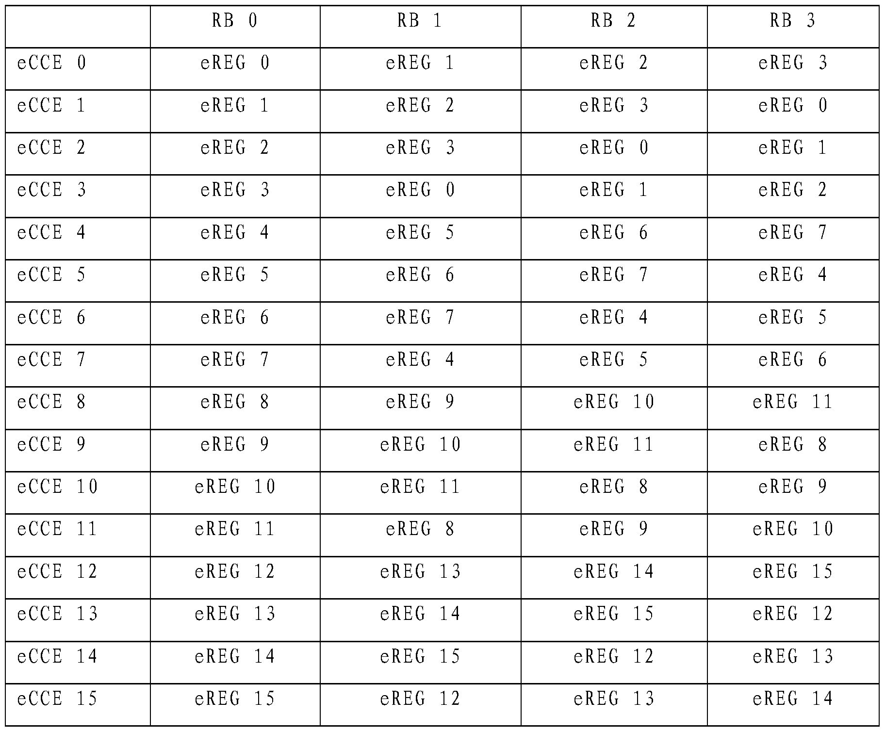
- k eCCE is Q- ⁇ , ⁇ is 3, m e brain is 0-15, M is 16, 0 is 0 or 8; such an eCCE contains 8 eREGs, that is, there are two eREGs in each resource block.
- Table 7 According to the above method, the results obtained according to other formulas and parameter values are not described.
- the use of the formula form in this embodiment is equivalent to the eREG in the resource block after the packet representing the eCCE in the form of a table.
- the method for transmitting control information enables the base station to group the RBs before transmitting the control information, and configure the eREGs that form the same eCCE into the non-adjacent RBs, thereby reducing the channel frequency diversity is poor.
- the problem thereby reducing the probability of loss of information of the terminal device, and improving the performance of the communication system.
- the embodiment of the present invention provides a method for transmitting control information, as shown in FIG. 8a, including:
- the embodiment mainly provides a specific implementation manner in which a base station groups resource blocks.
- Table 3 shows the distributed virtual resource blocks (Virtual resource blocks of Distributed type, DVRB) An example of allocation.
- the DVRB 0 is composed of a PRB0 (Physical Resource Block) of an even slot and a PRB18 of an odd slot.
- PRB0 Physical Resource Block
- DVRB2 is composed of PRB18 of even time slots and PRB0 of odd time slots. It can be seen that DVRB0 and DVRB2 are a pair of paired DVRBs, which together occupy PRB0 and PRB18 of one subframe.
- the S802 may include a method flow of S8021 to S8023.
- the physical resource block number N corresponding to the even time slot and the odd time slot and the physical resource block number M corresponding to the even time slot and the odd time slot are divided into the same group.
- the base station may allocate a DVRB set for the ePDCCH distributed transmission, and at least two DVRBs, which are used to support ePDCCH distributed transmission, or ePDCCH distributed transmission and ePDCCH centralized transmission.
- the set of DVRBs supporting ePDCCH distributed transmission includes N DVRBs, where N is an even Number.
- a DVRB contains M e REGs, numbered ⁇ (0 ⁇ m ⁇ M-1), and at least two e REGs are in different DVRBs.
- the resources of the ePDCCH distributed transmission are allocated by the DVRB.
- the DVRB number of the even time slot is also used in the odd time slot, that is, the allocated DVRB number corresponds to one PRB number in one subframe, and one eCCE includes at least one pair of matched DVRBs. At least two eREGs in the corresponding DVRB. As shown in Table 4, one eCCE includes at least one eVRG of DVRBs 0 and 2, respectively, or one eCCE contains at least one eVRG of DVRBs 1 and 3, respectively. For example:
- the number of the DVRB to which the eREGO is included in the eCCE 0 is: DVRB 0 and DVRB 2, that is, the number of the PRBs in which the eREGOs that make up the eCCE 0 are 0 and 18.
- PRB 0 and PRB 18 are not adjacent and are separated by 17 PRBs.
- the base station can group the PRBs in the same manner, so that the PRBs in each group are not adjacent, and the interval is 17.
- the resource blocks in which the enhanced resource elements implementing the enhanced control channel elements are located are not adjacent, such that the enhanced resource elements constituting the enhanced control channel elements have greater frequency diversity.
- the S802 may include a method flow of S8024 to S8025.
- S8024 Acquire high layer signaling in the base station, and configure at least two resource blocks according to the high layer signaling.
- the base station may obtain the high layer signaling, and configure at least two sets of non-contiguous resource blocks according to the high layer signaling, so that the resource blocks in which the enhanced resource unit that constitutes the enhanced control channel unit is located are not adjacent, thereby The enhanced resource elements that make up the enhanced control channel elements have greater frequency diversity.
- the resource allocation is performed by the ePDCCH distributed transmission resource configuration field in the RRC ConnectionReconfiguration signaling by the radio resource control 'J connection'.
- the resource allocation is performed by the ePDCCH distributed transmission resource configuration field in the RRC ConnectionReconfiguration signaling by the radio resource control 'J connection'.
- Table 5 four groups of resource blocks are configured. Group resource blocks correspond to two non-adjacent physical resource blocks
- S8025 Group the at least two groups of resource blocks into one group.
- the method for transmitting control information provided in this embodiment enables the base station to group the RBs before transmitting the control information, and configure the eREGs that form the same e CCE into the non-adjacent RBs, thereby reducing channel frequency diversity.
- the problem of poorness reduces the probability of loss of information of the terminal device and improves the performance of the communication system.
- the embodiment of the present invention provides a method for transmitting control information, as shown in FIG. 9, which includes: This embodiment mainly provides a specific implementation manner in which a terminal device groups resource blocks.
- the terminal device UE determines the enhanced resource unit group eREG number in the resource block RB, and determines the specific processing manner of the location of the resource unit corresponding to the enhanced resource unit group according to the enhanced resource unit group number.
- the specific embodiments described in the embodiments are not described herein again.
- the interleaver of the determined enhanced resource unit group number according to the interleaver, determining at least two enhanced resource unit groups corresponding to the enhanced control channel unit.
- the specific processing manner of the interleaver determined by the terminal device may refer to the specific implementation manner described in the foregoing embodiments, and details are not described herein again.
- the location of the element determines the location of the corresponding resource unit corresponding to the enhanced control channel unit.
- the terminal device determines, according to the interleaver, an enhanced resource unit group that constitutes at least two of the enhanced control channel units, and then determines the enhanced control channel unit according to the location of the resource unit corresponding to the enhanced control channel unit and the enhanced resource unit group.
- the manner of the location of the corresponding resource unit is different. For the specific processing manner, reference may be made to the specific implementation manner described in the foregoing embodiments, and details are not described herein again.
- the terminal device can mitigate the problem of poor channel frequency diversity when processing the control information sent by the base station. Therefore, the probability of loss of the information received by the terminal device is reduced, and the performance of the communication system is improved.
- the embodiment of the present invention provides a method for transmitting control information, as shown in FIG. 10, which includes: This embodiment mainly provides another implementation manner in which a terminal device groups resource blocks.
- the terminal device UE determines the enhanced resource unit group eREG in the resource block RB.
- the terminal device UE determines the enhanced resource unit group eREG in the resource block RB.
- the terminal device determines, according to the grouping of the resource block by the base station and the location of the resource element corresponding to the resource element group, the manner in which the location of the resource unit corresponding to the enhanced control channel unit in the resource block group is different, and the specific processing manner
- the specific embodiments described in the foregoing embodiments may be referred to, and details are not described herein again.
- the embodiment of the present invention provides a method for transmitting control information, as shown in FIG. 11, including: a first configuration module 1 1 1 for determining an enhanced resource unit group eREG number in a resource block RB, Determining, according to the enhanced resource unit group number in the resource block RB, an enhanced resource unit group corresponding resource unit location;
- the interleaving module 112 is configured to interleave the enhanced resource unit group number, and determine the enhanced control channel unit eCCE according to the at least two enhanced resource unit groups after the interleaving.
- the first mapping module 113 determines the location of the corresponding resource unit corresponding to the enhanced control channel unit according to the location of the enhanced control channel unit and the enhanced resource unit group corresponding resource unit.
- the first transmission module 114 is configured to transmit corresponding control information at a location of the resource unit corresponding to the control channel unit.
- the apparatus for transmitting control information provided by the embodiment can interleave the eREG before the transmission of the control information by using the interleaving module, and configure the eREGs of the same eCCE to be contiguous RBs, thereby reducing channel frequency diversity.
- the problem of poorness reduces the probability of loss of information of the terminal device and improves the performance of the communication system.
- An embodiment of the present invention provides a base station device, including:
- the first configuration module 121 is configured to determine an enhanced resource unit group eREG number in the resource block RB, and determine an enhanced resource unit group corresponding resource unit location according to the enhanced resource unit group number in the resource block R B.
- the first configuration module 121 includes: a first identification sub-module 1211, configured to determine a resource block number.
- the first locating sub-module 1212 is configured to determine, according to the resource block number and the enhanced resource unit group number, a location of the resource element group corresponding resource unit in the resource block.
- the first positioning submodule 1212 includes:
- RB « k is a resource block numbered 3 ⁇ 4 .
- eREG is an enhanced resource unit group numbered in RB « k .
- the first template extraction unit 12122 is configured to acquire a preset template according to the template identifier.
- the first template analyzing unit 12123 is configured to acquire, according to the preset template, a location of the preset template corresponding resource unit.
- the first configuration unit 12124 is configured to determine, according to the preset location of the template corresponding resource unit, a location of the resource element group corresponding to the resource unit in the resource block.
- the first positioning sub-module 1212 includes: a first analyzing unit 12125, configured to determine a subcarrier offset value according to the resource block number.
- the first offset unit 12126 is configured to determine, according to the subcarrier offset value, the preset template, and the enhanced resource unit group number in the resource block, the location of the resource element group corresponding resource unit in the resource block.
- the first configuration module 121 includes: a second identification sub-module 1213, configured to determine a cell identifier.
- the second locating sub-module 1214 is configured to determine, according to the cell identifier and the enhanced resource unit group number in the resource block, a location of an enhanced resource unit group corresponding to the resource unit in the resource block corresponding to the cell identifier.
- the second positioning submodule 1214 includes:
- RB « k is a resource block numbered 3 ⁇ 4 .
- eREG is an enhanced resource unit group numbered in RB « k .
- the second template extraction unit 12142 is configured to obtain a preset template according to the template identifier.
- the second template analyzing unit 12143 is configured to acquire, according to the preset template, a location of the preset template corresponding resource unit.
- the second configuration unit 12144 is configured to determine, according to the preset location of the template corresponding resource unit, a location of the resource element group corresponding resource unit in the resource block corresponding to the cell identifier.
- the second positioning sub-module 1214 includes: a second analyzing unit 12145, configured to determine a subcarrier offset value according to the cell identifier.
- the second offset unit 12146 is configured to determine, according to the subcarrier offset value and the preset template, a location of the resource unit corresponding to the enhanced resource unit group in the resource block corresponding to the cell identifier.
- the interleaving module 122 is configured to interleave the enhanced resource unit group number, and form the interleaved at least two enhanced resource unit groups into the enhanced control channel unit eCCE.
- the interleaving module 122 includes:
- the first statistic sub-module 1221 is configured to obtain the number of enhanced resource units or preset values included in one resource block.
- the first statistic sub-module 1221 is further configured to:
- the interleaving pre-processing sub-module 1222 is configured to determine an interleaver.
- the number of rows or columns of the interleaver is the number of enhanced resource unit groups included in one resource block or a multiple of the number; or the number of rows or columns of the interleaver is preset 4, 8, One of 12, 16 or 32.
- interleaving pre-processing sub-module 1222 is further configured to:
- the interleaving sub-module 1223 is configured to interleave the enhanced resource element group numbers in the resource block according to the interleaver to obtain an enhanced resource unit group after interleaving.
- the first grouping sub-module 1224 is configured to obtain, according to the sequence of the enhanced resource unit groups after the interleaving, the grouping of the enhanced resource unit groups, where each group is an eCCE.
- the interleaving module 122 includes: a first number extraction sub-module 1225, configured to obtain an enhanced resource unit number, and an enhanced resource included in a resource block. The number of units and the resource block number of the enhanced resource unit that constitutes one control channel element.
- the first re-numbering sub-module 1226 is configured to re-number each of the enhanced resource units that are to be formed into the enhanced resource unit of the same control channel unit according to a preset rule.
- the second grouping sub-module 1227 is configured to group the enhanced resource unit groups according to the new numbering sequence of the enhanced resource unit group, and each group is an eCCE
- the first mapping module 123 determines, according to the location of the enhanced control channel unit and the enhanced resource unit group corresponding resource unit, the location of the corresponding resource unit corresponding to the enhanced control channel unit.
- the first transmission module 124 is configured to transmit corresponding control information at a location of the resource unit corresponding to the control channel unit.
- the apparatus for transmitting control information can interleave the eREG through the interleaving module, so that the eREGs that form the same eCCE are configured into the non-adjacent RBs, thereby alleviating the problem of poor channel frequency diversity. Therefore, the probability of loss of information of the terminal device is reduced, and the performance of the communication system is improved; on the other hand, the difference between the different enhanced control channel units can be reduced by the first configuration module, and the base station processing enhancement is mitigated.
- the complexity of the compensation and the control of the power allocation increase the complexity of the implementation, and the working efficiency of the base station is improved, thereby further improving the performance of the communication system.
- An embodiment of the present invention provides a base station device, including:
- the second configuration module 131 is configured to determine an enhanced resource unit group eREG in the resource block RB.
- the resource block grouping module 132 is configured to group the resource blocks.
- the resource block grouping module 132 includes:
- the second number extraction sub-module 1321 is configured to determine the number of the virtual resource block DVRB.
- the number analysis sub-module 1322 is configured to determine an even time slot according to the number of the virtual resource block. Corresponding physical resource block number N and physical resource block number M corresponding to the odd time slot.
- the third grouping submodule 1323 is configured to divide the physical resource block number N corresponding to the even time slot and the odd time slot and the physical resource block number M corresponding to the even time slot and the odd time slot into the same group.
- the resource block grouping module 132 includes:
- the high-level signaling acquisition sub-module 1324 is configured to acquire high-level signaling in the base station, and configure at least two resource blocks according to the high-layer signaling.
- the fourth grouping sub-module 1325 is configured to group the at least two groups of resource blocks into one group.
- the second mapping module 133 is configured to map the control information to the enhanced resource unit group in the resource block after the grouping.
- the second transmission module 134 is configured to transmit the mapped control information.
- the apparatus for transmitting control information provided in this embodiment can group the RBs by the resource block grouping module before the transmission of the control information, and configure the eREGs that constitute the same eCCE into the non-adjacent RBs, thereby reducing the channel frequency.
- the problem of poor diversity reduces the probability of loss of information of the terminal device and improves the performance of the communication system.
- An embodiment of the present invention provides a terminal device, as shown in FIG. 14, including:
- the first location determining module 141 is configured to determine an enhanced resource unit group eREG in the resource block RB And determining, according to the enhanced resource unit group number in the resource block RB, the location of the resource element corresponding to the enhanced resource unit group;
- the terminal device UE determines the enhanced resource unit group eREG number in the resource block RB, and determines the location of the resource unit corresponding to the enhanced resource unit group according to the enhanced resource unit group number.
- the manner of processing refer to the specific implementation manners described in the foregoing embodiments, and details are not described herein again.
- a first determining module 1 4 2 an interleaver for determining the enhanced resource unit group number, according to the interleaver, determining at least two enhanced resource unit groups corresponding to the enhanced control channel unit; according to the enhanced control channel unit And the location of the resource unit corresponding to the enhanced resource unit group, determining the location of the corresponding resource unit corresponding to the enhanced control channel unit;
- the specific processing manner of the interleaver determined by the terminal device may refer to the specific implementation manner described in the foregoing embodiments, and details are not described herein again.
- the terminal device determines, according to the interleaver, an enhanced resource unit group that constitutes at least two of the enhanced control channel units, and then determines the enhanced control channel unit according to the location of the resource unit corresponding to the enhanced control channel unit and the enhanced resource unit group.
- the manner of the location of the corresponding resource unit is different. For the specific processing manner, reference may be made to the specific implementation manner described in the foregoing embodiments, and details are not described herein again.
- the first receiving module 1 4 3 is configured to receive control information that is sent by the base station at a location of the corresponding resource unit of the enhanced control channel unit;
- the apparatus for transmitting control information provided by the foregoing embodiment reduces the problem that the channel frequency diversity is poor, because the eREGs that form the same e CCE are configured in the non-adjacent RBs, thereby reducing the reception time of the terminal device.
- the probability of loss of information increases the performance of the communication system.
- An embodiment of the present invention provides a terminal device, as shown in FIG.
- a second determining module 1 5 1 configured to determine an enhanced resource unit group eREG number in the resource block RB, and determine, according to the enhanced resource unit group number, a location of the corresponding resource unit group corresponding to the resource unit;
- the terminal device UE determines the enhanced resource unit group eREG number in the resource block RB, and determines the location of the resource unit corresponding to the enhanced resource unit group according to the enhanced resource unit group number.
- the manner of processing refer to the specific implementation manners described in the foregoing embodiments, and details are not described herein again.
- the third determining module 1 2 2 is configured to acquire a grouping situation of the resource block by the base station; and the manner in which the terminal device acquires the grouping situation of the resource block by the base station is different, and the specific processing is performed.
- the second mapping module 1 5 3 is configured to determine, according to the grouping of the resource block by the base station and the location of the resource element group corresponding to the resource unit, the location of the corresponding resource unit of the enhanced control channel unit in the resource block group;
- the terminal device determines, according to the grouping of the resource block by the base station and the location of the resource element corresponding to the resource element group, the manner in which the location of the resource unit corresponding to the enhanced control channel unit in the resource block group is different, and the specific processing manner
- the specific embodiments described in the foregoing embodiments may be referred to, and details are not described herein again.
- the second receiving module 154 is configured to receive, by the base station, control information that is sent by the location of the enhanced control channel unit corresponding to the resource unit in the resource block group.
- the apparatus for transmitting control information provided by the embodiment reduces the problem of poor channel frequency diversity due to the eREG configuration of the same eCCE to the non-adjacent RBs, thereby reducing the probability of information loss when the terminal device receives the information. , improve the performance of the communication system.
- Example 15
- An embodiment of the present invention provides a method for transmitting control information. As shown in FIG. 7, the method includes: S 701. Determine an enhanced resource unit group e RE G in a resource block RB.
- S702 group the resource blocks.
- the base station may directly group the resource blocks, so that the resource blocks in which the enhanced resource units that constitute the enhanced control channel unit are located are not adjacent.
- the eREGOs that make up the eCCE O are in RB0, RBI, and RB2, respectively, and the order of the original RBs in the system is: RBO-RB RB2- RB 3- RB4- RB5, then the base station can re-receive RB0, RB1, and RB2.
- the RBs are arranged in the order of RB0 - RB 3 - RB RB4 - RB2 - RB5 , thereby implementing RB0, RB1.
- RB2 is not adjacent.
- S 703 Map control information to the enhanced resource unit group in the resource block after the grouping.
- an optional specific implementation includes:
- the enhanced control channel unit numbered k eCCE Determining, by the enhanced control channel unit numbered k eCCE , the number of the enhanced resource unit group in the resource block numbered n RB , where the m eREG includes:
- m eREG (k eCCE + n RB ) modM .
- M is a value determined by the first parameter value, where the first parameter value includes an enhanced number of resource element groups included in the enhanced control channel unit, or a quantity included in the grouped resource block The number of resource blocks, or the number of enhanced resource unit groups contained in the resource block.
- ⁇ is the second offset value of the enhanced resource unit group in the resource block
- O is the first offset value of the enhanced resource unit group in the resource block
- ⁇ is the enhanced control channel unit weighting factor.
- P ffset or 0 ⁇ or 2 is a predefined positive integer value or a positive integer value configured by higher layer control signaling, for example, Any positive integer between the predefined 0-M.
- n RB is ⁇ brain is 0-15
- M is 4, 0.
- Is 0, that is, one eCCE contains 4 eREGs.
- ⁇ brain ( ⁇ +3 ⁇ 4 + 0.) "1 0 (1 + ⁇ /)
- the eREG in the grouped resource block corresponding to the eCCE in Table 8 below can be obtained.
- the formula in the present embodiment is equivalent to the eREG in the resource block after the grouping of the eCCE in the form of a table.
- the control information is mapped to the enhanced resource unit group in the resource block after the packet corresponding to one or more different enhanced control channel units.
- the method for transmitting control information enables the base station to group the RBs before transmitting the control information, and configure the eREGs that form the same eCCE into the non-adjacent RBs, thereby reducing the channel frequency diversity is poor.
- the problem thereby reducing the probability of loss of information of the terminal device, and improving the performance of the communication system.
- the storage medium may be a magnetic disk, an optical disk, a read-only memory (ROM), or a random access memory (RAM).
- ROM read-only memory
- RAM random access memory
Landscapes
- Engineering & Computer Science (AREA)
- Signal Processing (AREA)
- Computer Networks & Wireless Communication (AREA)
- Mobile Radio Communication Systems (AREA)
Abstract
Description


Claims
Priority Applications (9)
| Application Number | Priority Date | Filing Date | Title |
|---|---|---|---|
| KR1020157005240A KR101720598B1 (ko) | 2012-08-02 | 2012-09-27 | 제어 정보 송신 방법, 장치, 및 시스템 |
| CN201280001932.7A CN103270715B (zh) | 2012-08-02 | 2012-09-27 | 传输控制信息的方法、装置及系统 |
| EP12882433.1A EP2871796B1 (en) | 2012-08-02 | 2012-09-27 | Method, apparatus and system for transmitting control information |
| CA2880651A CA2880651C (en) | 2012-08-02 | 2012-09-27 | Method, apparatus, and system for transmitting control information |
| US14/611,783 US9654263B2 (en) | 2012-08-02 | 2015-02-02 | Method, apparatus, and system for transmitting control information |
| ZA2015/00924A ZA201500924B (en) | 2012-08-02 | 2015-02-09 | Method,apparatus and system for transmotting control information |
| US15/486,138 US10264570B2 (en) | 2012-08-02 | 2017-04-12 | Method, apparatus, and system for transmitting control information |
| US16/256,273 US10785762B2 (en) | 2012-08-02 | 2019-01-24 | Method, apparatus, and system for transmitting control information |
| US16/256,317 US10764883B2 (en) | 2012-08-02 | 2019-01-24 | Method, apparatus, and system for transmitting control information |
Applications Claiming Priority (4)
| Application Number | Priority Date | Filing Date | Title |
|---|---|---|---|
| CNPCT/CN2012/079607 | 2012-08-02 | ||
| PCT/CN2012/079607 WO2014019208A1 (zh) | 2012-08-02 | 2012-08-02 | 传输控制信息的方法、装置及系统 |
| PCT/CN2012/081510 WO2014019276A1 (zh) | 2012-08-02 | 2012-09-17 | 传输控制信息的方法、装置及系统 |
| CNPCT/CN2012/081510 | 2012-09-17 |
Related Child Applications (1)
| Application Number | Title | Priority Date | Filing Date |
|---|---|---|---|
| US14/611,783 Continuation US9654263B2 (en) | 2012-08-02 | 2015-02-02 | Method, apparatus, and system for transmitting control information |
Publications (1)
| Publication Number | Publication Date |
|---|---|
| WO2014019283A1 true WO2014019283A1 (zh) | 2014-02-06 |
Family
ID=50027130
Family Applications (3)
| Application Number | Title | Priority Date | Filing Date |
|---|---|---|---|
| PCT/CN2012/079607 Ceased WO2014019208A1 (zh) | 2012-08-02 | 2012-08-02 | 传输控制信息的方法、装置及系统 |
| PCT/CN2012/081510 Ceased WO2014019276A1 (zh) | 2012-08-02 | 2012-09-17 | 传输控制信息的方法、装置及系统 |
| PCT/CN2012/082147 Ceased WO2014019283A1 (zh) | 2012-08-02 | 2012-09-27 | 传输控制信息的方法、装置及系统 |
Family Applications Before (2)
| Application Number | Title | Priority Date | Filing Date |
|---|---|---|---|
| PCT/CN2012/079607 Ceased WO2014019208A1 (zh) | 2012-08-02 | 2012-08-02 | 传输控制信息的方法、装置及系统 |
| PCT/CN2012/081510 Ceased WO2014019276A1 (zh) | 2012-08-02 | 2012-09-17 | 传输控制信息的方法、装置及系统 |
Country Status (7)
| Country | Link |
|---|---|
| US (4) | US9654263B2 (zh) |
| EP (1) | EP2871796B1 (zh) |
| KR (1) | KR101720598B1 (zh) |
| CN (2) | CN107181711A (zh) |
| CA (1) | CA2880651C (zh) |
| WO (3) | WO2014019208A1 (zh) |
| ZA (1) | ZA201500924B (zh) |
Families Citing this family (9)
| Publication number | Priority date | Publication date | Assignee | Title |
|---|---|---|---|---|
| CN105281878A (zh) * | 2014-07-25 | 2016-01-27 | 中兴通讯股份有限公司 | 一种资源单元映射方法及装置 |
| CN106921478A (zh) * | 2015-12-28 | 2017-07-04 | 夏普株式会社 | 窄带物联网物理下行信道的复用方法、基站和用户设备 |
| WO2017132955A1 (zh) | 2016-02-04 | 2017-08-10 | 华为技术有限公司 | 控制信息传输方法及基站与终端 |
| CN108282308B (zh) * | 2017-01-06 | 2022-10-14 | 中兴通讯股份有限公司 | 参考信号的处理方法及装置、设备 |
| CN110383746B (zh) * | 2017-04-28 | 2022-03-01 | Lg 电子株式会社 | 接收下行链路控制信道的方法和装置 |
| CN108809572B (zh) * | 2017-05-04 | 2023-12-01 | 华为技术有限公司 | 通信方法和通信装置 |
| CN108809581B (zh) | 2017-05-05 | 2021-12-21 | 华为技术有限公司 | 一种传输资源分配方法、数据发送方法及装置 |
| CN115567974A (zh) * | 2017-08-11 | 2023-01-03 | 华为技术有限公司 | 一种信息的发送方法及设备 |
| WO2019054691A1 (en) * | 2017-09-15 | 2019-03-21 | Samsung Electronics Co., Ltd. | METHOD AND APPARATUS FOR TRANSMITTING CONTROL INFORMATION IN A WIRELESS COMMUNICATION SYSTEM |
Citations (2)
| Publication number | Priority date | Publication date | Assignee | Title |
|---|---|---|---|---|
| CN101702644A (zh) * | 2009-11-02 | 2010-05-05 | 中兴通讯股份有限公司 | 一种物理混合重传指示信道的传输方法和装置 |
| CN102420685A (zh) * | 2011-11-07 | 2012-04-18 | 电信科学技术研究院 | 一种传输控制信息的方法及装置 |
Family Cites Families (27)
| Publication number | Priority date | Publication date | Assignee | Title |
|---|---|---|---|---|
| KR101500729B1 (ko) | 2007-09-24 | 2015-03-09 | 엘지전자 주식회사 | 무선통신 시스템에서 자원할당 방법 |
| CN101159470B (zh) | 2007-11-02 | 2012-09-05 | 中兴通讯股份有限公司 | 下行控制信令指示信道到物理资源的映射方法 |
| CN101212416B (zh) | 2007-12-25 | 2011-11-30 | 中兴通讯股份有限公司 | 一种物理信道的映射方法 |
| KR100913099B1 (ko) * | 2008-01-07 | 2009-08-21 | 엘지전자 주식회사 | 분산형 가상자원블록 스케쥴링 방법 |
| CN101252422B (zh) * | 2008-03-20 | 2013-06-05 | 中兴通讯股份有限公司 | 物理混合重传指示信道的分配方法 |
| CN101594215B (zh) | 2008-05-26 | 2013-08-07 | 中兴通讯股份有限公司 | 控制信道单元数量确定方法及装置、控制信道管理方法 |
| CN101895988B (zh) * | 2009-05-22 | 2013-06-05 | 中兴通讯股份有限公司 | 一种控制信道资源的分配方法及装置 |
| US8583128B2 (en) | 2009-07-13 | 2013-11-12 | Intel Mobile Communications GmbH | Apparatus and method for mapping physical control channels |
| CN102082600A (zh) * | 2009-12-01 | 2011-06-01 | 中兴通讯股份有限公司 | 中继链路下行控制信息配置方法及传输基站、中继站与方法 |
| WO2011132946A2 (ko) * | 2010-04-22 | 2011-10-27 | 엘지전자 주식회사 | 무선 통신 시스템에서 기지국과 릴레이 노드 간의 신호 송수신 방법 및 이를 위한 장치 |
| WO2011137383A1 (en) | 2010-04-30 | 2011-11-03 | Interdigital Patent Holdings, Inc. | Downlink control in heterogeneous networks |
| KR101868622B1 (ko) | 2010-06-17 | 2018-06-18 | 엘지전자 주식회사 | R-pdcch 전송 및 수신 방법과 그 장치 |
| US8548514B2 (en) * | 2010-08-11 | 2013-10-01 | Lg-Ericsson Co., Ltd. | Method for resource element group downsizing of R-PDCCH and mobile telecommunication system for the same |
| CN102395206B (zh) | 2011-11-08 | 2015-07-15 | 电信科学技术研究院 | 下行控制信息的传输方法和设备 |
| CN102611524B (zh) | 2011-12-19 | 2015-02-04 | 电信科学技术研究院 | 一种传输信息的方法、系统及设备 |
| CN102573094B (zh) | 2012-01-17 | 2015-04-08 | 电信科学技术研究院 | 一种传输dci的方法及装置 |
| US9179456B2 (en) * | 2012-02-07 | 2015-11-03 | Samsung Electronics Co., Ltd. | Methods and apparatus for downlink control channels transmissions in wireless communications systems |
| WO2013141801A1 (en) * | 2012-03-19 | 2013-09-26 | Telefonaktiebolaget L M Ericsson (Publ) | Aggregation of resources in enhanced control channels |
| US9497756B2 (en) * | 2012-03-25 | 2016-11-15 | Comcast Cable Communications, Llc | Base station radio resource management |
| CN102612094A (zh) | 2012-04-01 | 2012-07-25 | 华为技术有限公司 | 一种控制信令资源单元确定方法、基站及用户设备 |
| KR102098055B1 (ko) | 2012-04-30 | 2020-04-07 | 삼성전자 주식회사 | 무선 통신 시스템의 제어 채널 송수신 방법 및 장치 |
| US20130301562A1 (en) * | 2012-05-09 | 2013-11-14 | Mediatek, Inc. | Methods for Resource Multiplexing of Distributed and Localized transmission in Enhanced Physical Downlink Control Channel |
| KR20150035500A (ko) | 2012-06-25 | 2015-04-06 | 엘지전자 주식회사 | 무선 통신 시스템에서 향상된 제어 채널을 송신하는 방법 및 이를 위한 장치 |
| JP5829987B2 (ja) | 2012-07-23 | 2015-12-09 | 株式会社Nttドコモ | 無線通信方法、無線通信システム及び無線基地局 |
| WO2014017822A2 (ko) * | 2012-07-24 | 2014-01-30 | 엘지전자 주식회사 | 무선 통신 시스템에서 제어 정보를 전송하는 방법 및 이를 위한 장치 |
| WO2014019181A1 (zh) | 2012-08-01 | 2014-02-06 | 华为技术有限公司 | 一种控制信道传输方法及装置 |
| WO2014019202A1 (zh) | 2012-08-02 | 2014-02-06 | 华为技术有限公司 | 增强型物理下行控制信道传输方法及设备 |
-
2012
- 2012-08-02 WO PCT/CN2012/079607 patent/WO2014019208A1/zh not_active Ceased
- 2012-09-17 WO PCT/CN2012/081510 patent/WO2014019276A1/zh not_active Ceased
- 2012-09-27 WO PCT/CN2012/082147 patent/WO2014019283A1/zh not_active Ceased
- 2012-09-27 CA CA2880651A patent/CA2880651C/en active Active
- 2012-09-27 CN CN201710258292.2A patent/CN107181711A/zh active Pending
- 2012-09-27 EP EP12882433.1A patent/EP2871796B1/en active Active
- 2012-09-27 KR KR1020157005240A patent/KR101720598B1/ko active Active
- 2012-09-27 CN CN201280001932.7A patent/CN103270715B/zh active Active
-
2015
- 2015-02-02 US US14/611,783 patent/US9654263B2/en active Active
- 2015-02-09 ZA ZA2015/00924A patent/ZA201500924B/en unknown
-
2017
- 2017-04-12 US US15/486,138 patent/US10264570B2/en active Active
-
2019
- 2019-01-24 US US16/256,273 patent/US10785762B2/en active Active
- 2019-01-24 US US16/256,317 patent/US10764883B2/en active Active
Patent Citations (2)
| Publication number | Priority date | Publication date | Assignee | Title |
|---|---|---|---|---|
| CN101702644A (zh) * | 2009-11-02 | 2010-05-05 | 中兴通讯股份有限公司 | 一种物理混合重传指示信道的传输方法和装置 |
| CN102420685A (zh) * | 2011-11-07 | 2012-04-18 | 电信科学技术研究院 | 一种传输控制信息的方法及装置 |
Non-Patent Citations (2)
| Title |
|---|
| See also references of EP2871796A4 * |
| TEXAS INSTRUMENTS: "Need for Multiplexing Localized and Distributed ePDCCHs in one PRB", 3GPP TSG RAN WG1 #69, R1-122743, 21 May 2012 (2012-05-21) - 25 May 2012 (2012-05-25), XP050600926 * |
Also Published As
| Publication number | Publication date |
|---|---|
| KR20150039813A (ko) | 2015-04-13 |
| EP2871796A1 (en) | 2015-05-13 |
| US10764883B2 (en) | 2020-09-01 |
| US20190174467A1 (en) | 2019-06-06 |
| US9654263B2 (en) | 2017-05-16 |
| WO2014019276A1 (zh) | 2014-02-06 |
| CN107181711A (zh) | 2017-09-19 |
| CN103270715B (zh) | 2017-04-26 |
| CN103270715A (zh) | 2013-08-28 |
| WO2014019208A1 (zh) | 2014-02-06 |
| EP2871796B1 (en) | 2021-06-02 |
| US20190159184A1 (en) | 2019-05-23 |
| ZA201500924B (en) | 2021-09-29 |
| US10264570B2 (en) | 2019-04-16 |
| US10785762B2 (en) | 2020-09-22 |
| CA2880651A1 (en) | 2014-02-06 |
| KR101720598B1 (ko) | 2017-04-10 |
| US20150146669A1 (en) | 2015-05-28 |
| CA2880651C (en) | 2019-05-14 |
| US20170223682A1 (en) | 2017-08-03 |
| EP2871796A4 (en) | 2015-07-08 |
Similar Documents
| Publication | Publication Date | Title |
|---|---|---|
| CN106059738B (zh) | 在增强型物理下行控制信道上传输信息的方法及设备 | |
| WO2014019283A1 (zh) | 传输控制信息的方法、装置及系统 | |
| US10425933B2 (en) | System and method for resource management in a communications system | |
| JP6746779B2 (ja) | 無線通信システムにおいて信号を送信又は受信する方法及びそのための装置 | |
| US10623156B2 (en) | Methods for transmitting and receiving control channel, base station, and user equipment | |
| RU2490823C2 (ru) | Способы и системы для выделения csi-rs-ресурсов в системах по усовершенствованному стандарту lte | |
| WO2013139211A1 (zh) | ePDCCH资源确定方法及装置 | |
| TW201824908A (zh) | 傳輸信息的方法、網絡設備和終端設備 | |
| EP3089418B1 (en) | Method and apparatus for mapping between enhanced downlink control channel resource and antenna port | |
| WO2016197472A1 (zh) | 一种增强型物理下行控制信道处理方法、装置及存储介质 | |
| WO2017101632A1 (zh) | 信号处理方法及装置 | |
| CN104041161B (zh) | 控制信道的传输、接收方法、基站和用户设备 | |
| CN103684701A (zh) | 配置ePDCCH的空间分集的方法和设备 | |
| WO2013170687A1 (zh) | 无线通信系统中的通信方法和设备 | |
| CN103916349B (zh) | 增强公共搜索空间的解调参考符号的配置方法和装置 | |
| WO2017028071A1 (zh) | 下行控制信息的接收、发送方法及装置 | |
| CN103891343B (zh) | 增强的物理下行控制信道ePDCCH的发送方法、基站和终端 |
Legal Events
| Date | Code | Title | Description |
|---|---|---|---|
| 121 | Ep: the epo has been informed by wipo that ep was designated in this application |
Ref document number: 12882433 Country of ref document: EP Kind code of ref document: A1 |
|
| ENP | Entry into the national phase |
Ref document number: 2880651 Country of ref document: CA |
|
| NENP | Non-entry into the national phase |
Ref country code: DE |
|
| WWE | Wipo information: entry into national phase |
Ref document number: 2012882433 Country of ref document: EP |
|
| ENP | Entry into the national phase |
Ref document number: 20157005240 Country of ref document: KR Kind code of ref document: A |