WO2014020649A1 - 直動装置 - Google Patents
直動装置 Download PDFInfo
- Publication number
- WO2014020649A1 WO2014020649A1 PCT/JP2012/004898 JP2012004898W WO2014020649A1 WO 2014020649 A1 WO2014020649 A1 WO 2014020649A1 JP 2012004898 W JP2012004898 W JP 2012004898W WO 2014020649 A1 WO2014020649 A1 WO 2014020649A1
- Authority
- WO
- WIPO (PCT)
- Prior art keywords
- rolling element
- rolling
- seal
- linear motion
- grease
- Prior art date
- Legal status (The legal status is an assumption and is not a legal conclusion. Google has not performed a legal analysis and makes no representation as to the accuracy of the status listed.)
- Ceased
Links
Images


Classifications
-
- F—MECHANICAL ENGINEERING; LIGHTING; HEATING; WEAPONS; BLASTING
- F16—ENGINEERING ELEMENTS AND UNITS; GENERAL MEASURES FOR PRODUCING AND MAINTAINING EFFECTIVE FUNCTIONING OF MACHINES OR INSTALLATIONS; THERMAL INSULATION IN GENERAL
- F16H—GEARING
- F16H25/00—Gearings comprising primarily only cams, cam-followers and screw-and-nut mechanisms
- F16H25/18—Gearings comprising primarily only cams, cam-followers and screw-and-nut mechanisms for conveying or interconverting oscillating or reciprocating motions
- F16H25/20—Screw mechanisms
- F16H25/22—Screw mechanisms with balls, rollers, or similar members between the co-operating parts; Elements essential to the use of such members
- F16H25/2204—Screw mechanisms with balls, rollers, or similar members between the co-operating parts; Elements essential to the use of such members with balls
-
- F—MECHANICAL ENGINEERING; LIGHTING; HEATING; WEAPONS; BLASTING
- F16—ENGINEERING ELEMENTS AND UNITS; GENERAL MEASURES FOR PRODUCING AND MAINTAINING EFFECTIVE FUNCTIONING OF MACHINES OR INSTALLATIONS; THERMAL INSULATION IN GENERAL
- F16H—GEARING
- F16H25/00—Gearings comprising primarily only cams, cam-followers and screw-and-nut mechanisms
- F16H25/18—Gearings comprising primarily only cams, cam-followers and screw-and-nut mechanisms for conveying or interconverting oscillating or reciprocating motions
- F16H25/20—Screw mechanisms
- F16H25/22—Screw mechanisms with balls, rollers, or similar members between the co-operating parts; Elements essential to the use of such members
-
- F—MECHANICAL ENGINEERING; LIGHTING; HEATING; WEAPONS; BLASTING
- F16—ENGINEERING ELEMENTS AND UNITS; GENERAL MEASURES FOR PRODUCING AND MAINTAINING EFFECTIVE FUNCTIONING OF MACHINES OR INSTALLATIONS; THERMAL INSULATION IN GENERAL
- F16H—GEARING
- F16H25/00—Gearings comprising primarily only cams, cam-followers and screw-and-nut mechanisms
- F16H25/18—Gearings comprising primarily only cams, cam-followers and screw-and-nut mechanisms for conveying or interconverting oscillating or reciprocating motions
- F16H25/20—Screw mechanisms
- F16H25/24—Elements essential to such mechanisms, e.g. screws, nuts
- F16H25/2418—Screw seals, wipers, scrapers or the like
-
- F—MECHANICAL ENGINEERING; LIGHTING; HEATING; WEAPONS; BLASTING
- F16—ENGINEERING ELEMENTS AND UNITS; GENERAL MEASURES FOR PRODUCING AND MAINTAINING EFFECTIVE FUNCTIONING OF MACHINES OR INSTALLATIONS; THERMAL INSULATION IN GENERAL
- F16H—GEARING
- F16H57/00—General details of gearing
- F16H57/04—Features relating to lubrication or cooling or heating
- F16H57/048—Type of gearings to be lubricated, cooled or heated
- F16H57/0497—Screw mechanisms
-
- F—MECHANICAL ENGINEERING; LIGHTING; HEATING; WEAPONS; BLASTING
- F16—ENGINEERING ELEMENTS AND UNITS; GENERAL MEASURES FOR PRODUCING AND MAINTAINING EFFECTIVE FUNCTIONING OF MACHINES OR INSTALLATIONS; THERMAL INSULATION IN GENERAL
- F16C—SHAFTS; FLEXIBLE SHAFTS; ELEMENTS OR CRANKSHAFT MECHANISMS; ROTARY BODIES OTHER THAN GEARING ELEMENTS; BEARINGS
- F16C29/00—Bearings for parts moving only linearly
- F16C29/08—Arrangements for covering or protecting the ways
- F16C29/084—Arrangements for covering or protecting the ways fixed to the carriage or bearing body movable along the guide rail or track
Definitions
- the present invention relates to a linear motion device such as a ball screw, a ball spline, or a linear guide used in a clean environment such as a semiconductor manufacturing device or a liquid crystal display panel manufacturing device.
- a linear motion device such as a ball screw, a ball spline, or a linear guide used in a clean environment such as a semiconductor manufacturing device or a liquid crystal display panel manufacturing device.
- This linear motion device such as a ball screw or linear guide has a raceway member having a rolling element rolling part on the outer peripheral surface and a loaded rolling element rolling part facing the rolling element rolling part on the inner peripheral surface.
- a plurality of rolling elements movably loaded in a rolling element rolling path formed by a moving member that is movable relative to the member, and a rolling element rolling part and a load rolling element rolling part;
- a rolling element circuit that forms an endless rolling element passage by communicating the starting point and the end point of the rolling element rolling path.
- the ball screw is a screw shaft
- the moving member is a nut
- the rolling element is a ball.
- the ball screw includes a screw shaft having a spiral ball rolling groove (rolling element rolling portion) on the outer peripheral surface, and a load ball rolling groove facing the ball rolling groove (rolling member rolling portion) of the screw shaft ( A spiral ball formed by a nut having an inner circumferential surface (loaded rolling element rolling part), a ball rolling groove (rolling element rolling part), and a loaded ball rolling groove (loaded rolling element rolling part). And a plurality of balls loaded in a rolling path (rolling element rolling path) so as to roll freely.
- the ball screw is provided with a ball circulation path (rolling element circulation path) that forms an endless ball path (rolling element passage) by communicating the starting point and the end point of the ball rolling path.
- the oil in the grease applied between the ball rolling path and the rolling elements is scattered as fine particles.
- the scattered fine particles cause defects in products such as wafers and liquid crystal panels.
- cleanliness, vacuum grease (fluid lubricant), solid lubricant, etc. are used when cleanliness is required, such as in semiconductor manufacturing equipment and liquid crystal panel manufacturing equipment. This suppresses the amount of fine particles (oil) generated from the lubricant in the ball and the ball contact portion.
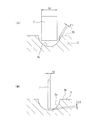
- the linear guide 101 shown in FIG. 7 has a rolling element circuit including a raceway member 102 having a rolling element rolling part 102a and a loaded rolling element rolling part (not shown) facing the rolling element rolling part 102a.
- the moving member 103 that is movable relative to the track member 102, a plurality of rolling elements (not shown) arranged in the rolling element circulation path, and the moving member 103 are in contact with the track member 102.
- the clearance seals 104 and 105 that close the gap between the track member 102 and the moving member 103 are provided.
- the clearance seal 104 is attached to the end portion of the moving member 103 in the axial direction by an attaching screw 106.
- the gap seal 104 attached to the axial end of the moving member 103 includes a plurality of thin plate-like first and second plates 107 and 108 that are alternately stacked, and the first and second plates 107 and 108. And a presser plate 109 to which is attached.
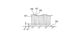
- the first and second plates 107 and 213 constituting the clearance seal 104 move along the guide rail track member 102 while maintaining a slight gap without contacting the track member 102. Describing this gap, as shown in FIG. 8, the gap ⁇ between the second plate 218 and the track member 102 is larger than the gap ⁇ between the first plate 107 and the track member 102 and has an uneven shape.
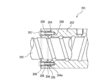
- the outer seal disposed on the outermost side of the nut 203 in the axial direction is the non-contact seal 206 and the grease pool spaces 208 and 209 are provided.
- the grease pool space is provided using the outer seal as a contact seal.
- dust generation due to wear of the contact seal is reduced.
- the outer seal is a non-contact seal and no grease reservoir space is provided, dust generation due to the scattering of grease is reduced, and the lubrication performance is also improved.
- the linear guide 101 shown in FIG. 7 and the ball screw 201 shown in FIG. 9 have the following problems. That is, in the case of the linear guide 101 shown in FIG. 7, the gap ⁇ between the first plate 107 and the track member 102 shown in FIG. Is set to 0.25 mm or less at the position closest to the track member 102. The smaller the gap ⁇ , the greater the resistance when gas flows through the passage. Therefore, it is desirable to set the target value of the gap ⁇ to about 0.05 to 0.06 mm or less. Yes.
- the gap amount of 0.25 mm is very large. Further, it is desirable to set the target value of the clearance ⁇ to about 0.05 to 0.06 mm or less, but when the clearance between the seal unit and the raceway member is actually set to 0.05 mm or less. Depending on the attachment of the seal member (especially in the case of a ball screw), there is a high possibility that the seal member contacts the track member. When the seal member comes into contact with the raceway member, there is a problem in that fine particles are generated. Therefore, in consideration of processing tolerances of moving members and seal members, the gap between the seal member and the raceway member is actually 0.05 mm or more, and fine particles considered in the semiconductor field may leak to the outside. There is sex.
- the present invention has been made in view of the above-described problems, and the object thereof is to manufacture a semiconductor that can suppress as much as possible the amount of fine particles generated between the rolling element rolling path and the rolling element leaking out of the apparatus.
- An object of the present invention is to provide a linear motion device suitable for a clean environment such as a device or a liquid crystal display panel manufacturing device.
- a linear motion device includes a raceway member extending in the axial direction and having a rolling element rolling part on an outer peripheral surface, and a load rolling element facing the rolling element rolling part.
- a plurality of rolling elements that are slidably loaded therein, a rolling element circulation path that forms an endless rolling element path by communicating a starting point and an end point of the rolling element rolling path, and an axial direction of the moving member
- each of the pair of seal members is orthogonal to the axial direction of the track member while being attached to the moving member. 0.025 to 0.1 relative to the track member when cut along the direction. Is formed into a shape having a gap mm range, it is characterized in that the worked penetration 175 or more 250 or less grease between the rolling element rolling path and the rolling element.
- each of the pair of seal members along the axial direction of the track member is 0.1 mm or more and less than 1.2 mm.
- the material of each of the pair of seal members may be a resin material or a metal material.
- each of the pair of seal members is configured by a plurality of seal bodies, and the plurality of seal bodies are formed along the axial direction of the moving member. You may arrange
- each of the pair of seal members is attached to the moving member, and when the track member is cut along a direction orthogonal to the axial direction of the track member, In contrast, grease having a blending degree of 175 to 250 is applied between the rolling element rolling path and the rolling element, so that the gap is in the range of 0.025 to 0.15 mm.
- a hard grease layer is formed between the race member and the seal member. For this reason, the gap between the seal member and the raceway member is extremely small as compared with the case where the seal member alone provides a gap with respect to the raceway member, and fine particles generated between the rolling element rolling path and the rolling element are reduced.
- the inside of the moving member can be sealed, and the amount of fine particles generated between the rolling element rolling path and the rolling element can be suppressed as much as possible. For this reason, it can be set as the linear motion apparatus suitable for clean environments, such as a semiconductor manufacturing apparatus and a liquid crystal display panel manufacturing apparatus.
- the amount of fine particles leaking out of the apparatus is decreased until the gap between the seal member and the raceway member reaches 0 to 0.025 mm, and the gap is reduced to 0. From 025 mm to 0.15 mm, the amount of fine particles leaking out of the apparatus is almost unchanged, and when the gap is larger than 0.15 mm, the amount of fine particles leaking out of the apparatus is almost proportional to the increase of the gap amount. The amount increases.
- the linear motion device when the thickness of each of the pair of seal members along the axial direction of the track member is 0.1 mm or more and less than 1.2 mm, the linear motion device is a ball screw, and the track
- the member is a screw shaft
- the gap between the seal member and the groove bottom of the screw shaft can be maintained at an appropriate size, and the sealing member can be easily processed to ensure an appropriate rigidity and the sealing performance is stable.
- the thickness of each seal member is greater than 1.2 mm, the gap between the seal member and the groove bottom of the screw shaft is greater than 0.15 mm.
- the thickness of each seal member is less than 0.1 mm, it becomes difficult to process the seal member and its rigidity is lowered, and the sealing performance is not stable.
- each of the pair of seal members is a resin material or a metal material
- mechanical strength, heat resistance, wear resistance, chemical resistance, machinability and cost are considered.
- a resin material or a metal material may be appropriately selected.
- each of the pair of seal members is constituted by a plurality of seal bodies, and the plurality of seal bodies are formed along the axial direction of the movable member. If it arrange
- FIG. 2 is a cross-sectional view taken along line 2-2 in FIG. 1 (cut along a direction orthogonal to the axial direction of the track member). It is the figure which represented typically the clearance gap vicinity between a sealing member and a track member. It is a graph which shows the relationship between the gap
- the difference in the gap amount between the seal member and the raceway member due to the difference in the thickness of the seal member is shown, (A) is a schematic diagram when the seal member is thick, and (B) is a schematic diagram when the seal member is thin. is there.
- the attachment method of a sealing member is shown, (A) is sectional drawing when attaching a sealing member to a moving member with a retaining ring, (B) is sectional drawing when attaching a sealing member to a moving member with a set screw. It is a disassembled perspective view which shows the linear guide used in the vacuum environment of a prior art example. It is a figure which shows the state of the clearance gap between the sealing member and track member in the linear guide shown in FIG. It is sectional drawing which shows the ball screw which can be used in the clean environment of a prior art example.
- FIG. 1 is a cross-sectional view taken along the axial direction of a raceway member showing an embodiment of a linear motion device according to the present invention.
- FIG. 2 is a cross-sectional view taken along line 2-2 in FIG. 1 (cut along a direction orthogonal to the axial direction of the track member).
- FIG. 3 is a diagram schematically showing the vicinity of the gap between the seal member and the raceway member.
- a linear motion device 1 shown in FIG. 1 is a ball screw suitable for a clean environment such as a semiconductor manufacturing device or a liquid crystal display panel manufacturing device, and includes a raceway member (screw shaft) 2, a moving member (nut) 3, and a plurality of A rolling element (ball) 4 is provided.
- the track member 2 has a cylindrical shape extending in the axial direction along the central axis CL, and a rolling element rolling part (rolling element rolling groove) 2a having a predetermined lead is formed on the outer peripheral surface 2b thereof. It is preferable not to provide relief at the groove bottom of the rolling element rolling part (rolling element rolling groove) 2a.
- the moving member 3 has a substantially cylindrical shape, and the inner diameter thereof is larger than the outer diameter of the track member 2, and is externally fitted to the moving member 2 with a predetermined gap.
- the inner circumferential surface of the moving member 3 has a lead equal to the rolling element rolling part 2a of the raceway member 2, and is a loaded rolling element rolling part (loaded rolling element rolling groove) facing the rolling element rolling part 2a. 3a is formed.
- a rolling element rolling path 5 having a substantially circular cross section is formed by the rolling element rolling part 2 a of the track member 2 and the loaded rolling element rolling part 3 a of the moving member 3.
- a plurality of rolling elements 4 are arranged in the rolling element rolling path 5 so as to be capable of rolling.
- the moving member 3 is provided with a grease supply hole 3b for supplying grease to the rolling element rolling path 5.
- the linear motion device 1 has a rolling element circulation path 6 that forms an endless rolling element path by communicating the starting point and the end point of the rolling element rolling path 5.
- This rolling element circulation path 6 is formed inside the moving member 3 and is connected to a circular path 6a having a circular cross section extending linearly along the axial direction and a scooping member 6b provided at one end of the circulation path 6a in the axial direction.
- the passage 6c is formed, and the passage 6c is formed in a scooping member 6b provided at the other axial end of the circulation path 6a.
- a passage 6c formed in a scooping member 6b provided at one end of the circulation path 6a in the axial direction is connected to a starting point of the rolling element rolling path 5 and formed in a scooping member 6b provided at the other end in the axial direction of the circulation path 6a.
- the made passage 6 c is connected to the end point of the rolling element rolling path 5.
- a pair of seal members 7 are attached to both ends of the moving member 3 in the axial direction, and the pair of seal members 7 suppress dust generation from the inside of the moving member 3.
- fine particles (particles) of the linear motion device 1 are generated when the lubricant (grease or oil) is wound up between the rolling element 4 and the rolling element rolling path 5 by friction when the rolling element 4 revolves.
- How to seal the fine particles in the moving member 3 in the moving member 3 is indispensable for improving the cleanliness. In particular, it is important in a linear motion apparatus used in a clean environment such as a semiconductor manufacturing apparatus and a liquid crystal display panel manufacturing apparatus.
- each seal member 7 is composed of one seal body, and is attached to the moving member 3 as shown in FIG. 2 along a direction orthogonal to the axial direction of the track member 2.
- the track member 2 is formed in a shape having a gap ⁇ in the range of 0.025 to 0.15 mm. That is, each seal member 7 is formed in an annular shape, and has a through hole 7a through which the track member 2 penetrates. The through hole 7a is in a state where the seal member 7 is attached to the moving member 3,
- the track member 2 When cut along a direction perpendicular to the axial direction of the track member 2, the track member 2 has a shape having a gap ⁇ in the range of 0.025 to 0.15 mm.
- the gap ⁇ is either one of the raceway member 2 (in the case of FIG. It means the geometrically minimum distance to the corner.
- the gap ⁇ between the seal member 7 and the track member 2 is 0.025 mm or more, the seal member 7 does not come into contact with the track member 2 and fine particles are not generated from the seal member 7 itself.
- the gap ⁇ between the seal member 7 and the track member 2 is smaller than 0.025 mm, the possibility of the seal member 7 coming into contact with the track member 2 is high in consideration of processing accuracy and assembly accuracy of the seal member 7 and the like. When the seal member 7 comes into contact with the track member 2, fine particles may be generated thereby.
- grease having a blending degree of 175 to 250 is applied between the rolling element rolling path 5 and the rolling element 4.
- a clean grease or a vacuum grease is preferably used.
- a hard grease layer (seal film) G is formed between the raceway member 2 and the seal member 7 as shown in FIG. As a result, the gap between the seal member 7 and the raceway member 2 is reduced by the amount of the grease layer G as shown in FIG. , ⁇ .
- the fine particles generated between the rolling element rolling path 5 and the rolling element 4 can be sealed in the moving member 3, and the fine particles generated between the rolling element rolling path 5 and the rolling element 4 leak out of the apparatus.
- the amount can be suppressed as much as possible. For this reason, it can be set as the linear motion apparatus 1 suitable for clean environments, such as a semiconductor manufacturing apparatus and a liquid crystal display panel manufacturing apparatus.
- FIG. 4 is a graph showing the relationship between the amount of clearance between the seal member and the track member and the amount of fine particles leaking out of the apparatus.
- FIG. 4 shows a case where the gap amount is set to 0 mm, 0.025 mm, 0.050 mm, 0.10 mm, 0.15 mm, 0.20 mm, 0.30 mm, and 0.50 mm using grease having a blending degree of 280.
- the gap amount is set to 0 mm, 0.025 mm, 0.050 mm, 0.10 mm, 0.15 mm, 0.20 mm, 0.30 mm, 0.50 mm using a grease having a blending degree of 250.
- the relationship between the gap amount and the amount of fine particles leaking out of the apparatus is shown.
- the grease with a blending consistency of 280 has a larger amount of fine particles leaking out of the apparatus than the grease with a blending consistency of 250, and increasing the gap amount increases the amount of fine particles in proportion. Yes.
- the amount of fine particles leaking out of the apparatus decreases until the gap amount reaches 0 to 0.025 mm, and the gap reaches a state of 0.025 mm to 0.15 mm.
- the amount of fine particles leaking out of the apparatus is almost unchanged, and when the gap is larger than 0.15 mm, it leaks out of the apparatus almost in proportion to the increase in the gap amount, as in the case of grease having a blending consistency of 280.
- each of the seal members 7 is 0.025 to 0.15 mm with respect to the track member 2 when the seal member 7 is cut with a cut surface perpendicular to the axial direction of the track member 2 while being attached to the moving member 3. It was formed in a shape having a gap ⁇ in the range.
- FIG. 5 shows the difference in the gap amount between the seal member and the raceway member due to the difference in the thickness of the seal member, (A) is a schematic diagram when the seal member is thick, and (B) is when the seal member is thin FIG.
- the rolling element rolling part (rolling element rolling groove) 2a of the raceway member 2 has a shape connected by two circular arcs having a curvature. Two arcs are connected.
- the thickness t of the seal member 7 is set to 0.1 mm or more and less than 1.2 mm.
- the linear motion device 1 is a ball screw and the raceway member 2 is a screw shaft
- the gap between the seal member and the groove bottom of the screw shaft can be maintained at an appropriate size, and the seal member is processed. Is easy and secures moderate rigidity, and the sealing performance is stable.
- the thickness t of each seal member 7 is greater than 1.2 mm, the gap between the seal member and the groove bottom of the screw shaft will be greater than 0.15 mm.
- the thickness t of each seal member 7 is smaller than 0.1 mm, it becomes difficult to process the seal member and its rigidity is lowered, and the sealing performance is not stable.
- each seal member 7 is a resin material or a metal material such as polyacetal which is excellent in mechanical strength, heat resistance, wear resistance, chemical resistance, machinability and cost.
- the material of each seal member 7 is preferably a material excellent in non-water absorption and dimensional stability.
- FIG. 6A and 6B show a method for attaching the seal member, wherein FIG. 6A is a cross-sectional view when the seal member is attached to the moving member by a retaining ring, and FIG. 6B is a cross-sectional view when the seal member is attached to the moving member by a set screw. is there.
- the pair of seal members 7 are attached to both ends of the moving member 3 in the axial direction, and each seal member 7 is attached to the end of the moving member 3 in the axial direction.
- it is fixed by a retaining ring 8 or fixed by a plurality of set screws 9 as shown in FIG. 6 (B).
- the linear motion device 1 may be applied not only to a ball screw but also to a linear guide or a ball spline.
- the track member is a guide rail
- the moving member is a slider.
- the raceway member is a cylindrical raceway member
- the moving member is a ball spline nut.
- each of the pair of seal members 7 is configured by a single seal body
- the present invention is not limited thereto, and each of the pair of seal members 7 is configured by a plurality of seal bodies.
- the plurality of seal bodies may be arranged along the axial direction of the moving member 2 at a pitch with an interval equal to or greater than the thickness of each seal body. In this case, the amount of fine particles generated between the rolling element rolling path 5 and the rolling element 4 can be further suppressed.
Landscapes
- Engineering & Computer Science (AREA)
- General Engineering & Computer Science (AREA)
- Mechanical Engineering (AREA)
- Transmission Devices (AREA)
- Bearings For Parts Moving Linearly (AREA)
- Lubricants (AREA)
Description
図7に示すリニアガイド101は、転動体転走部102aを有する軌道部材102と、転動体転走部102aに対向する負荷転動体転走部(図示せず)を含む転動体循環路を有し、軌道部材102に対して相対的に移動可能な移動部材103と、転動体循環路に配列される複数の転動体(図示せず)と、移動部材103に設けられ、軌道部材102に接触することなく、軌道部材102と移動部材103との間の隙間を塞ぐすきまシール104,105とを備えている。すきまシール104は、取付ねじ106により移動部材103の軸方向端部に取り付けられる。
図9に示すボールねじ201において、ナット203の凹部204内に、軸方向内側から順に、環状のスペーサ205、非接触シール206、環状のスペーサ205、非接触シール206を配置し、これらをボルト207で凹部204の端面204aに固定する。これにより、隣り合う非接触シール206とスペーサ205とねじ軸202で囲まれた空間208と、内側の非接触シール206とスペーサ205と凹部204の端面204aとで囲まれた空間209とが生じ、これら空間208,209がグリース溜まり空間となるものである。
即ち、図7に示すリニアガイド101の場合、すきまシール104を移動部材103に取り付けた状態で、図8に示す第1のプレート107と軌道部材102との間の隙間αは、第1プレート107が軌道部材102に最も接近した位置で0.25mm以下に設定される、とされている。そして、隙間αは小さければ小さいほど、通路に気体が流れるときの抵抗が大きくなるので、隙間αの目標値を0.05~0.06mm程度あるいはそれ以下に設定するのが望ましい、とされている。
従って、本発明は上述の問題点に鑑みてなされたものであり、その目的は、転動体転走路と転動体との間で発生した微粒子が装置外に漏れ出る量を極力抑制できる、半導体製造装置や液晶表示パネル製造装置等のクリーン環境に好適な直動装置を提供することにある。
更に、この直動装置において、前記1対のシール部材の各々の材質が、樹脂材料又は金属材料であるとよい。
加えて、この直動装置において、前記1対シール部材の各々が、複数枚のシール体で構成され、該複数枚のシール体が、前記移動部材の軸方向に沿って前記各シール体の厚さ以上の間隔をあけたピッチで配置されてもよい。
また、この直動装置において、前記1対のシール部材の各々が、複数枚のシール体で構成され、該複数枚のシール体が、前記移動部材の軸方向に沿って前記各シール体の厚さ以上の間隔をあけたピッチで配置されると、転動体転走路と転動体との間で発生した微粒子が装置外に漏れ出る量をより抑制することができる。
軌道部材2は、中心軸CLに沿って軸方向に延びる円筒形状で、その外周面2bに、所定のリードを有する転動体転走部(転動体転走溝)2aが形成されている。転動体転走部(転動体転走溝)2aの溝底には、逃げを設けないことが好ましい。
このように、シール部材7と軌道部材2との間の隙間δが0.025mm以上なので、シール部材7が軌道部材2に接触せず、シール部材7自身からの微粒子は発生しない。シール部材7と軌道部材2との間の隙間δが0.025mmよりも小さいと、シール部材7等の加工精度や組立精度を考慮すると、シール部材7が軌道部材2に接触する可能性が高く、シール部材7が軌道部材2に接触すると、それによって微粒子が発生してしまうおそれがある。
図4には、混和ちょう度280のグリースを用いて当該隙間量を0mm、0.025mm、0.050mm、0.10mm、0.15mm、0.20mm、0.30mm、0.50mmにした場合と、混和ちょう度250のグリースを用いて当該隙間量を0mm、0.025mm、0.050mm、0.10mm、0.15mm、0.20mm、0.30mm、0.50mmにした場合の、当該隙間量と装置外に漏れ出る微粒子の量との関係が示されている。
図6(A)及び図6(B)に示すように、1対のシール部材7は、移動部材3の軸方向両端部に取り付けられ、各シール部材7は移動部材3の軸方向端部に、図6(A)に示すように、止輪8で固定されるか、あるいは図6(B)に示すように、複数の止めねじ9により固定される。
例えば、直動装置1としては、ボールねじのみならず、リニアガイドやボールスプライン等に適用してもよい。リニアガイドに適用した場合には、軌道部材は案内レール、移動部材はスライダである。また、ボールスプラインに適用した場合には、軌道部材は円筒形状の軌道部材が用いられ、移動部材にはボールスプラインナットが用いられる。
2 軌道部材
2a 転動体転走部
2b 軌道部材の外周面
3 移動部材
3a 負荷転動体転走部
3b 給脂穴
4 転動体
5 転動体転走路
6 転動体循環路
6a 循環路
6b すく上げ部材
6c通路
7 シール部材
7a 貫通孔
8 止輪
9 止めねじ
δ 隙間
t シール部材の厚さ
G グリース層
Claims (4)
- 軸方向に延び、転動体転走部を外周面に有する軌道部材と、前記転動体転走部に対向する負荷転動体転走部を内周面に有し、前記軌道部材に対して相対的に移動可能な移動部材と、前記転動体転走部と前記負荷転動体転走部とにより形成される転動体転走路内に転動自在に装填された複数の転動体と、前記転動体転走路の始点と終点とを連通させて無端状の転動体通路を形成する転動体循環路と、前記移動部材の軸方向両端に取り付けられた1対のシール部材とを備えた直動装置において、
前記1対のシール部材の各々は、前記移動部材に取り付けられた状態で、前記軌道部材の軸方向に対して直交する方向に沿って切断した際に、前記軌道部材に対して0.025~0.15mmの範囲の隙間を有する形状に形成され、前記転動体転走路と前記転動体との間に混和ちょう度175以上250以下のグリースを塗布したことを特徴とする直動装置。 - 前記軌道部材の軸方向に沿う前記1対のシール部材の各々の厚さが、0.1mm以上1.2mm未満であることを特徴とする請求項1記載の直動装置。
- 前記1対のシール部材の各々の材質が、樹脂材料又は金属材料であることを特徴とする請求項1又は2記載の直動装置。
- 前記1対シール部材の各々が、複数枚のシール体で構成され、該複数枚のシール体が、前記移動部材の軸方向に沿って前記各シール体の厚さ以上の間隔をあけたピッチで配置されることを特徴とする請求項1乃至3のうちいずれか一項に記載の直動装置。
Priority Applications (8)
| Application Number | Priority Date | Filing Date | Title |
|---|---|---|---|
| DE12747876.6T DE12747876T1 (de) | 2012-08-01 | 2012-05-01 | Vorrichtung für Lineare Bewegung |
| CN201280000747.6A CN103703279A (zh) | 2012-08-01 | 2012-08-01 | 直动装置 |
| KR1020127022010A KR101386304B1 (ko) | 2012-08-01 | 2012-08-01 | 직동장치 |
| JP2012538126A JPWO2014020649A1 (ja) | 2012-08-01 | 2012-08-01 | 直動装置 |
| EP12747876.6A EP2853775A4 (en) | 2012-08-01 | 2012-08-01 | LINEAR MOTION DEVICE |
| US13/581,200 US9261178B2 (en) | 2011-06-07 | 2012-08-01 | Linear device |
| PCT/JP2012/004898 WO2014020649A1 (ja) | 2012-08-01 | 2012-08-01 | 直動装置 |
| TW101130110A TWI470157B (zh) | 2012-08-01 | 2012-08-20 | Linear motion device |
Applications Claiming Priority (1)
| Application Number | Priority Date | Filing Date | Title |
|---|---|---|---|
| PCT/JP2012/004898 WO2014020649A1 (ja) | 2012-08-01 | 2012-08-01 | 直動装置 |
Publications (1)
| Publication Number | Publication Date |
|---|---|
| WO2014020649A1 true WO2014020649A1 (ja) | 2014-02-06 |
Family
ID=50027382
Family Applications (1)
| Application Number | Title | Priority Date | Filing Date |
|---|---|---|---|
| PCT/JP2012/004898 Ceased WO2014020649A1 (ja) | 2011-06-07 | 2012-08-01 | 直動装置 |
Country Status (7)
| Country | Link |
|---|---|
| EP (1) | EP2853775A4 (ja) |
| JP (1) | JPWO2014020649A1 (ja) |
| KR (1) | KR101386304B1 (ja) |
| CN (1) | CN103703279A (ja) |
| DE (1) | DE12747876T1 (ja) |
| TW (1) | TWI470157B (ja) |
| WO (1) | WO2014020649A1 (ja) |
Cited By (1)
| Publication number | Priority date | Publication date | Assignee | Title |
|---|---|---|---|---|
| CN109737025A (zh) * | 2019-02-25 | 2019-05-10 | 金职液压动力(金华)有限公司 | 一种摩擦和滚动复合作用的柱塞泵变量斜盘座 |
Families Citing this family (5)
| Publication number | Priority date | Publication date | Assignee | Title |
|---|---|---|---|---|
| CN104052188A (zh) * | 2014-07-02 | 2014-09-17 | 上海翱锐控制系统有限公司 | 精密电动缸 |
| JP6668652B2 (ja) * | 2015-09-18 | 2020-03-18 | 日本精工株式会社 | 直動案内装置、直動案内装置用エンドキャップ |
| JP2018134697A (ja) * | 2017-02-21 | 2018-08-30 | セイコーエプソン株式会社 | ロボット |
| CN107289083A (zh) * | 2017-07-01 | 2017-10-24 | 苏州健雄职业技术学院 | 一种快速移动螺母副 |
| CN110170877A (zh) * | 2019-05-24 | 2019-08-27 | 黄石百斯特智能科技股份有限公司 | 一种具有高强度的中空滚珠丝杠 |
Citations (6)
| Publication number | Priority date | Publication date | Assignee | Title |
|---|---|---|---|---|
| JP2003343686A (ja) * | 2002-05-28 | 2003-12-03 | Nsk Ltd | 直動装置 |
| JP2006112517A (ja) * | 2004-10-14 | 2006-04-27 | Nsk Ltd | ボールねじ |
| WO2006054439A1 (ja) | 2004-11-22 | 2006-05-26 | Thk Co., Ltd. | 真空環境用運動案内装置 |
| JP2010169114A (ja) | 2009-01-20 | 2010-08-05 | Nsk Ltd | ボールねじ |
| JP2011190928A (ja) * | 2010-02-18 | 2011-09-29 | Nsk Ltd | ボールねじ |
| JP2011247404A (ja) * | 2010-04-26 | 2011-12-08 | Nsk Ltd | ボールねじ |
Family Cites Families (8)
| Publication number | Priority date | Publication date | Assignee | Title |
|---|---|---|---|---|
| JP4482168B2 (ja) * | 1998-11-30 | 2010-06-16 | 株式会社ツバキ・ナカシマ | ボールねじのシール装置 |
| EP1369608A3 (en) * | 2002-05-23 | 2005-06-01 | Nsk Ltd | Linear guide apparatus |
| JP2005007576A (ja) | 2003-06-16 | 2005-01-13 | Canon Inc | 印刷装置 |
| JP2007107590A (ja) | 2005-10-12 | 2007-04-26 | Nsk Ltd | ボールねじ用シール部材およびボールねじ |
| TW200734562A (en) * | 2006-03-03 | 2007-09-16 | Nak Sealing Technologies Corp | Sealing apparatus |
| JP5146293B2 (ja) * | 2008-12-09 | 2013-02-20 | 日本精工株式会社 | 直動装置 |
| CN102165221B (zh) * | 2009-12-17 | 2014-03-05 | 日本精工株式会社 | 滚珠丝杠 |
| CN201621243U (zh) * | 2010-02-05 | 2010-11-03 | 启东润泽机床附件有限公司 | 双返向器滚珠循环丝杠副 |
-
2012
- 2012-05-01 DE DE12747876.6T patent/DE12747876T1/de active Pending
- 2012-08-01 EP EP12747876.6A patent/EP2853775A4/en not_active Withdrawn
- 2012-08-01 WO PCT/JP2012/004898 patent/WO2014020649A1/ja not_active Ceased
- 2012-08-01 CN CN201280000747.6A patent/CN103703279A/zh active Pending
- 2012-08-01 KR KR1020127022010A patent/KR101386304B1/ko not_active Expired - Fee Related
- 2012-08-01 JP JP2012538126A patent/JPWO2014020649A1/ja active Pending
- 2012-08-20 TW TW101130110A patent/TWI470157B/zh not_active IP Right Cessation
Patent Citations (6)
| Publication number | Priority date | Publication date | Assignee | Title |
|---|---|---|---|---|
| JP2003343686A (ja) * | 2002-05-28 | 2003-12-03 | Nsk Ltd | 直動装置 |
| JP2006112517A (ja) * | 2004-10-14 | 2006-04-27 | Nsk Ltd | ボールねじ |
| WO2006054439A1 (ja) | 2004-11-22 | 2006-05-26 | Thk Co., Ltd. | 真空環境用運動案内装置 |
| JP2010169114A (ja) | 2009-01-20 | 2010-08-05 | Nsk Ltd | ボールねじ |
| JP2011190928A (ja) * | 2010-02-18 | 2011-09-29 | Nsk Ltd | ボールねじ |
| JP2011247404A (ja) * | 2010-04-26 | 2011-12-08 | Nsk Ltd | ボールねじ |
Non-Patent Citations (1)
| Title |
|---|
| See also references of EP2853775A4 * |
Cited By (1)
| Publication number | Priority date | Publication date | Assignee | Title |
|---|---|---|---|---|
| CN109737025A (zh) * | 2019-02-25 | 2019-05-10 | 金职液压动力(金华)有限公司 | 一种摩擦和滚动复合作用的柱塞泵变量斜盘座 |
Also Published As
| Publication number | Publication date |
|---|---|
| JPWO2014020649A1 (ja) | 2016-07-11 |
| CN103703279A (zh) | 2014-04-02 |
| TW201407064A (zh) | 2014-02-16 |
| EP2853775A1 (en) | 2015-04-01 |
| TWI470157B (zh) | 2015-01-21 |
| KR101386304B1 (ko) | 2014-04-17 |
| EP2853775A4 (en) | 2016-11-23 |
| KR20140026995A (ko) | 2014-03-06 |
| DE12747876T1 (de) | 2015-06-03 |
Similar Documents
| Publication | Publication Date | Title |
|---|---|---|
| WO2014020649A1 (ja) | 直動装置 | |
| EP3508763A1 (en) | Sliding component | |
| CN103261742B (zh) | 密封构件及使用该密封构件的直线运动引导装置 | |
| US9261178B2 (en) | Linear device | |
| WO2015093591A1 (ja) | 転がり軸受及びその製造方法 | |
| JP2014088886A (ja) | 直動装置 | |
| JP5786356B2 (ja) | 直動案内装置 | |
| JP2012255457A (ja) | 直動装置 | |
| JP2014001818A (ja) | ボールねじ、直動案内装置 | |
| Okabe et al. | Development of a vacuum-compatible hydrodynamic spindle using an ionic liquid as a lubricant | |
| JP2004270792A (ja) | 多点接触玉軸受 | |
| JP2008169998A (ja) | 組合せ玉軸受及び複列玉軸受 | |
| JP5891674B2 (ja) | 直動装置 | |
| CN205154900U (zh) | 滚轮式在四个象限互锁游隙的滑轨装置 | |
| CN100529448C (zh) | 薄壁轴承 | |
| WO2018225720A1 (ja) | 転がり軸受用保持器および転がり軸受 | |
| CA2871157C (en) | A mechanism for adjusting the rotation direction and speed of an inner ring and an outer ring of a rotary bearing | |
| US20090007710A1 (en) | Ball screw | |
| JP2017106520A (ja) | 軸受装置及び回転支持装置 | |
| JP2019105295A (ja) | 転がり案内装置および転がり案内装置に用いられる樹脂部材 | |
| CN121273770A (zh) | 耐高速高温的集成式磁力密封轴承结构 | |
| TW202219398A (zh) | 交叉滾子軸承 | |
| JP2007327630A (ja) | 直動装置 | |
| WO2024090536A1 (ja) | ボールねじ | |
| Miyake | Dust generation properties of solid lubricant film coated and perfluoropolyether lubricated ball bearings |
Legal Events
| Date | Code | Title | Description |
|---|---|---|---|
| ENP | Entry into the national phase |
Ref document number: 2012538126 Country of ref document: JP Kind code of ref document: A |
|
| ENP | Entry into the national phase |
Ref document number: 20127022010 Country of ref document: KR Kind code of ref document: A |
|
| REEP | Request for entry into the european phase |
Ref document number: 2012747876 Country of ref document: EP |
|
| WWE | Wipo information: entry into national phase |
Ref document number: 2012747876 Country of ref document: EP |
|
| WWE | Wipo information: entry into national phase |
Ref document number: 13581200 Country of ref document: US |
|
| 121 | Ep: the epo has been informed by wipo that ep was designated in this application |
Ref document number: 12747876 Country of ref document: EP Kind code of ref document: A1 |
|
| NENP | Non-entry into the national phase |
Ref country code: DE |