WO2014020951A1 - グリッド統合制御装置、グリッド制御システム、グリッド制御装置、プログラム、及び制御方法 - Google Patents
グリッド統合制御装置、グリッド制御システム、グリッド制御装置、プログラム、及び制御方法 Download PDFInfo
- Publication number
- WO2014020951A1 WO2014020951A1 PCT/JP2013/061322 JP2013061322W WO2014020951A1 WO 2014020951 A1 WO2014020951 A1 WO 2014020951A1 JP 2013061322 W JP2013061322 W JP 2013061322W WO 2014020951 A1 WO2014020951 A1 WO 2014020951A1
- Authority
- WO
- WIPO (PCT)
- Prior art keywords
- power
- grid
- amount
- supply
- demand
- Prior art date
- Legal status (The legal status is an assumption and is not a legal conclusion. Google has not performed a legal analysis and makes no representation as to the accuracy of the status listed.)
- Ceased
Links
Images


Classifications
-
- H—ELECTRICITY
- H02—GENERATION; CONVERSION OR DISTRIBUTION OF ELECTRIC POWER
- H02J—ELECTRIC POWER NETWORKS; CIRCUIT ARRANGEMENTS OR SYSTEMS FOR SUPPLYING OR DISTRIBUTING ELECTRIC POWER; SYSTEMS FOR STORING ELECTRIC ENERGY
- H02J3/00—Circuit arrangements for AC mains or AC distribution networks
- H02J3/04—Arrangements for connecting networks of the same frequency but supplied from different sources
- H02J3/06—Controlling the transfer of power between connected networks; Controlling load sharing between connected networks
-
- G—PHYSICS
- G05—CONTROLLING; REGULATING
- G05B—CONTROL OR REGULATING SYSTEMS IN GENERAL; FUNCTIONAL ELEMENTS OF SUCH SYSTEMS; MONITORING OR TESTING ARRANGEMENTS FOR SUCH SYSTEMS OR ELEMENTS
- G05B15/00—Systems controlled by a computer
- G05B15/02—Systems controlled by a computer electric
-
- H—ELECTRICITY
- H02—GENERATION; CONVERSION OR DISTRIBUTION OF ELECTRIC POWER
- H02J—ELECTRIC POWER NETWORKS; CIRCUIT ARRANGEMENTS OR SYSTEMS FOR SUPPLYING OR DISTRIBUTING ELECTRIC POWER; SYSTEMS FOR STORING ELECTRIC ENERGY
- H02J13/00—Circuit arrangements for providing remote monitoring or remote control of equipment in a power distribution network
- H02J13/13—Circuit arrangements for providing remote monitoring or remote control of equipment in a power distribution network characterised by the transmission of data to equipment in the power network
-
- H—ELECTRICITY
- H02—GENERATION; CONVERSION OR DISTRIBUTION OF ELECTRIC POWER
- H02J—ELECTRIC POWER NETWORKS; CIRCUIT ARRANGEMENTS OR SYSTEMS FOR SUPPLYING OR DISTRIBUTING ELECTRIC POWER; SYSTEMS FOR STORING ELECTRIC ENERGY
- H02J3/00—Circuit arrangements for AC mains or AC distribution networks
-
- H—ELECTRICITY
- H02—GENERATION; CONVERSION OR DISTRIBUTION OF ELECTRIC POWER
- H02J—ELECTRIC POWER NETWORKS; CIRCUIT ARRANGEMENTS OR SYSTEMS FOR SUPPLYING OR DISTRIBUTING ELECTRIC POWER; SYSTEMS FOR STORING ELECTRIC ENERGY
- H02J13/00—Circuit arrangements for providing remote monitoring or remote control of equipment in a power distribution network
- H02J13/12—Monitoring network conditions, e.g. electrical magnitudes or operational status
-
- H—ELECTRICITY
- H02—GENERATION; CONVERSION OR DISTRIBUTION OF ELECTRIC POWER
- H02J—ELECTRIC POWER NETWORKS; CIRCUIT ARRANGEMENTS OR SYSTEMS FOR SUPPLYING OR DISTRIBUTING ELECTRIC POWER; SYSTEMS FOR STORING ELECTRIC ENERGY
- H02J2105/00—Networks for supplying or distributing electric power characterised by their spatial reach or by the load
- H02J2105/50—Networks for supplying or distributing electric power characterised by their spatial reach or by the load for selectively controlling the operation of the loads
- H02J2105/54—Networks for supplying or distributing electric power characterised by their spatial reach or by the load for selectively controlling the operation of the loads according to a non-electrical condition, e.g. temperature
- H02J2105/55—Networks for supplying or distributing electric power characterised by their spatial reach or by the load for selectively controlling the operation of the loads according to a non-electrical condition, e.g. temperature according to an economic condition, e.g. tariff-based load management
-
- Y—GENERAL TAGGING OF NEW TECHNOLOGICAL DEVELOPMENTS; GENERAL TAGGING OF CROSS-SECTIONAL TECHNOLOGIES SPANNING OVER SEVERAL SECTIONS OF THE IPC; TECHNICAL SUBJECTS COVERED BY FORMER USPC CROSS-REFERENCE ART COLLECTIONS [XRACs] AND DIGESTS
- Y02—TECHNOLOGIES OR APPLICATIONS FOR MITIGATION OR ADAPTATION AGAINST CLIMATE CHANGE
- Y02B—CLIMATE CHANGE MITIGATION TECHNOLOGIES RELATED TO BUILDINGS, e.g. HOUSING, HOUSE APPLIANCES OR RELATED END-USER APPLICATIONS
- Y02B70/00—Technologies for an efficient end-user side electric power management and consumption
- Y02B70/30—Systems integrating technologies related to power network operation and communication or information technologies for improving the carbon footprint of the management of residential or tertiary loads, i.e. smart grids as climate change mitigation technology in the buildings sector, including also the last stages of power distribution and the control, monitoring or operating management systems at local level
- Y02B70/3225—Demand response systems, e.g. load shedding, peak shaving
-
- Y—GENERAL TAGGING OF NEW TECHNOLOGICAL DEVELOPMENTS; GENERAL TAGGING OF CROSS-SECTIONAL TECHNOLOGIES SPANNING OVER SEVERAL SECTIONS OF THE IPC; TECHNICAL SUBJECTS COVERED BY FORMER USPC CROSS-REFERENCE ART COLLECTIONS [XRACs] AND DIGESTS
- Y02—TECHNOLOGIES OR APPLICATIONS FOR MITIGATION OR ADAPTATION AGAINST CLIMATE CHANGE
- Y02B—CLIMATE CHANGE MITIGATION TECHNOLOGIES RELATED TO BUILDINGS, e.g. HOUSING, HOUSE APPLIANCES OR RELATED END-USER APPLICATIONS
- Y02B90/00—Enabling technologies or technologies with a potential or indirect contribution to GHG emissions mitigation
- Y02B90/20—Smart grids as enabling technology in buildings sector
-
- Y—GENERAL TAGGING OF NEW TECHNOLOGICAL DEVELOPMENTS; GENERAL TAGGING OF CROSS-SECTIONAL TECHNOLOGIES SPANNING OVER SEVERAL SECTIONS OF THE IPC; TECHNICAL SUBJECTS COVERED BY FORMER USPC CROSS-REFERENCE ART COLLECTIONS [XRACs] AND DIGESTS
- Y02—TECHNOLOGIES OR APPLICATIONS FOR MITIGATION OR ADAPTATION AGAINST CLIMATE CHANGE
- Y02E—REDUCTION OF GREENHOUSE GAS [GHG] EMISSIONS, RELATED TO ENERGY GENERATION, TRANSMISSION OR DISTRIBUTION
- Y02E60/00—Enabling technologies; Technologies with a potential or indirect contribution to GHG emissions mitigation
-
- Y—GENERAL TAGGING OF NEW TECHNOLOGICAL DEVELOPMENTS; GENERAL TAGGING OF CROSS-SECTIONAL TECHNOLOGIES SPANNING OVER SEVERAL SECTIONS OF THE IPC; TECHNICAL SUBJECTS COVERED BY FORMER USPC CROSS-REFERENCE ART COLLECTIONS [XRACs] AND DIGESTS
- Y04—INFORMATION OR COMMUNICATION TECHNOLOGIES HAVING AN IMPACT ON OTHER TECHNOLOGY AREAS
- Y04S—SYSTEMS INTEGRATING TECHNOLOGIES RELATED TO POWER NETWORK OPERATION, COMMUNICATION OR INFORMATION TECHNOLOGIES FOR IMPROVING THE ELECTRICAL POWER GENERATION, TRANSMISSION, DISTRIBUTION, MANAGEMENT OR USAGE, i.e. SMART GRIDS
- Y04S10/00—Systems supporting electrical power generation, transmission or distribution
- Y04S10/30—State monitoring, e.g. fault, temperature monitoring, insulator monitoring, corona discharge
-
- Y—GENERAL TAGGING OF NEW TECHNOLOGICAL DEVELOPMENTS; GENERAL TAGGING OF CROSS-SECTIONAL TECHNOLOGIES SPANNING OVER SEVERAL SECTIONS OF THE IPC; TECHNICAL SUBJECTS COVERED BY FORMER USPC CROSS-REFERENCE ART COLLECTIONS [XRACs] AND DIGESTS
- Y04—INFORMATION OR COMMUNICATION TECHNOLOGIES HAVING AN IMPACT ON OTHER TECHNOLOGY AREAS
- Y04S—SYSTEMS INTEGRATING TECHNOLOGIES RELATED TO POWER NETWORK OPERATION, COMMUNICATION OR INFORMATION TECHNOLOGIES FOR IMPROVING THE ELECTRICAL POWER GENERATION, TRANSMISSION, DISTRIBUTION, MANAGEMENT OR USAGE, i.e. SMART GRIDS
- Y04S20/00—Management or operation of end-user stationary applications or the last stages of power distribution; Controlling, monitoring or operating thereof
- Y04S20/20—End-user application control systems
- Y04S20/222—Demand response systems, e.g. load shedding, peak shaving
-
- Y—GENERAL TAGGING OF NEW TECHNOLOGICAL DEVELOPMENTS; GENERAL TAGGING OF CROSS-SECTIONAL TECHNOLOGIES SPANNING OVER SEVERAL SECTIONS OF THE IPC; TECHNICAL SUBJECTS COVERED BY FORMER USPC CROSS-REFERENCE ART COLLECTIONS [XRACs] AND DIGESTS
- Y04—INFORMATION OR COMMUNICATION TECHNOLOGIES HAVING AN IMPACT ON OTHER TECHNOLOGY AREAS
- Y04S—SYSTEMS INTEGRATING TECHNOLOGIES RELATED TO POWER NETWORK OPERATION, COMMUNICATION OR INFORMATION TECHNOLOGIES FOR IMPROVING THE ELECTRICAL POWER GENERATION, TRANSMISSION, DISTRIBUTION, MANAGEMENT OR USAGE, i.e. SMART GRIDS
- Y04S40/00—Systems for electrical power generation, transmission, distribution or end-user application management characterised by the use of communication or information technologies, or communication or information technology specific aspects supporting them
- Y04S40/12—Systems for electrical power generation, transmission, distribution or end-user application management characterised by the use of communication or information technologies, or communication or information technology specific aspects supporting them characterised by data transport means between the monitoring, controlling or managing units and monitored, controlled or operated electrical equipment
-
- Y—GENERAL TAGGING OF NEW TECHNOLOGICAL DEVELOPMENTS; GENERAL TAGGING OF CROSS-SECTIONAL TECHNOLOGIES SPANNING OVER SEVERAL SECTIONS OF THE IPC; TECHNICAL SUBJECTS COVERED BY FORMER USPC CROSS-REFERENCE ART COLLECTIONS [XRACs] AND DIGESTS
- Y04—INFORMATION OR COMMUNICATION TECHNOLOGIES HAVING AN IMPACT ON OTHER TECHNOLOGY AREAS
- Y04S—SYSTEMS INTEGRATING TECHNOLOGIES RELATED TO POWER NETWORK OPERATION, COMMUNICATION OR INFORMATION TECHNOLOGIES FOR IMPROVING THE ELECTRICAL POWER GENERATION, TRANSMISSION, DISTRIBUTION, MANAGEMENT OR USAGE, i.e. SMART GRIDS
- Y04S50/00—Market activities related to the operation of systems integrating technologies related to power network operation or related to communication or information technologies
- Y04S50/10—Energy trading, including energy flowing from end-user application to grid
Definitions
- the present invention relates to a grid integrated control device, a grid control system, a grid control device, a program, and a control method.
- a new power network that distributes autonomously controlled power systems has been proposed.
- One such power grid is the smart grid.
- this distributed power system is called a grid.
- the grid In addition to supplying power from an external main power grid with conventional power generation facilities, the grid has power generation facilities that use renewable energy such as wind power and solar power, and supplies power from those power generation facilities as well. There are many. By doing so, the power supply / demand balance can be adjusted more flexibly.
- Patent Document 1 discloses a comprehensive monitoring system that absorbs fluctuations in the amount of power supplied due to a failure of the main power system or suspension of use due to construction by adjusting the amount of power generated by renewable energy as described above.
- Patent Document 2 discloses a technology for exchanging information about power through data communication lines between grids that are arranged in a distributed manner, and allowing power to be interchanged between grids asynchronously.
- Patent Document 2 In order to adjust the power supply / demand balance more flexibly, a method of temporarily storing power by holding a power storage device in each grid has been proposed. This method is disclosed in Patent Document 2, for example.
- JP 2011-61931 A Japanese Patent No. 4783453 JP 2001-309559 A
- An object of the present invention is to provide a grid integrated control device, a program, and a control method that prevent generation of useless power transmission costs by performing power interchange in consideration of power transmission costs.
- the grid integrated control apparatus is a grid integrated control apparatus that controls at least two or more grids arranged in a distributed manner.
- the grid is connected to at least one or more other grids by power transmission lines, power transmission / reception means for transmitting / receiving power to / from other grids via the power transmission lines, and a communication line Grid control means for controlling the power transmission / reception means on the basis of a control instruction received from the grid integrated control apparatus connected via the network.
- At least one of the grids has power distribution means for distributing power to consumers who consume power.
- the said grid integrated control apparatus has the supply and demand electric power amount which shows the difference of the electric energy which this grid supplies to the said other grid, and the electric energy which this grid supplies from the said other grid about each said grid
- Supply / demand power amount information acquisition means for acquiring power amount information
- cost information acquisition means for acquiring cost information indicating the cost for transmission between the grids
- the supply / demand power amount information acquired by the supply / demand power amount information acquisition means And based on the cost information acquired by the cost information acquisition means, the total cost of power transmission between the grids is reduced under the condition that the demand of the grid from which the supply / demand power amount information has been acquired is satisfied.
- the control instruction to generate for controlling the power transmission by the head has a grid control instruction generation means for transmitting control instructions to ⁇ to each said grid.
- the grid control system includes a grid control device and a grid integrated control device that controls at least two or more grid control devices.
- the grid is connected to at least one other grid by a power transmission line, and has power transmission / reception means for transmitting and receiving power to and from the other grid via the power transmission line.
- At least one of the grids has power distribution means for distributing power to consumers who consume power.
- the grid control device includes a demand power amount acquisition unit that acquires a demand power amount that indicates the amount of power supplied from the other grid, and a supply power that indicates the amount of power that the grid supplies to the other grid.
- the grid integrated control device includes: a supply / demand power amount information acquisition unit that acquires the supply / demand power amount information from each grid control device; a cost information acquisition unit that acquires cost information indicating a cost for power transmission between the grids; Based on the supply / demand power amount information acquired by the supply / demand power amount information acquisition unit and the cost information acquired by the cost information acquisition unit, all the demands of the grid from which the supply / demand power information has been acquired are satisfied.
- the combination of the transmission source grid, the transmission destination grid and the transmission power amount is determined so as to reduce the total cost of power
- Another grid control system includes a grid control device that controls a grid and a grid integrated control device that controls at least two or more grid control devices.
- the grid is connected to the grid integrated control device via a communication line, is connected to at least one other grid with a power transmission line, and is connected to the other grid via the power transmission line.
- Power transmission / reception means for transmitting and receiving electric power between them.
- At least one of the grids has power distribution means for distributing power to consumers who consume power.
- the grid control device includes a grid control unit that controls the power transmission / reception unit in accordance with an instruction from the grid integrated control device connected via a communication line.
- the grid integrated control device includes a demand power amount acquisition unit that acquires a demand power amount indicating the amount of power supplied by the grid from another grid, and a supply that indicates the amount of power that the grid supplies to the other grid.
- Supply power amount acquisition means for acquiring power amount, and supply / demand power amount for calculating supply / demand power amount indicating a difference between the supply power amount acquired by the supply power amount acquisition means and the demand power amount acquired by the demand power amount acquisition means
- a calculation means a cost information acquisition means for acquiring cost information indicating a cost for power transmission between the grids; the supply / demand power amount acquired from the supply / demand power amount calculation means; and the cost acquired by the cost information acquisition means.
- the total cost of power transmission between the grids is reduced under the condition that all the demands of the grid that generated the supply and demand power information are satisfied.
- the grid control instruction generating means for transmitting an instruction to each of the grid controller.
- the grid control device controls the grid.
- the grid is connected to at least one other grid by a power transmission line, and has power transmission / reception means for transmitting and receiving power to and from the other grid via the power transmission line.
- At least one of the grids has power distribution means for distributing power to consumers who consume power.
- the said grid control apparatus shows the electric energy which the said grid supplies to the said other grid with the demand electric energy acquisition means which acquires the electric power demand which shows the electric energy supplied from the said other grid
- a supply power amount acquisition unit that acquires a supply power amount; and a supply and demand power amount that indicates a difference between the supply power amount acquired by the supply power amount acquisition unit and the demand power amount acquired by the demand power amount acquisition unit
- Supply / demand power amount calculation means and grid control means for controlling the power transmission / reception means in accordance with instructions from the grid integrated control apparatus connected to the grid control apparatus via a communication line.
- the grid integrated control device determines a combination of the transmission source grid, the transmission destination grid, and the transmission power amount based on the supply and demand power amount.
- the program provided by the present invention causes a computer to have a function of operating as a grid integrated control device provided by the present invention.
- the program causes the computer to have the functions of each functional component of the grid integrated control apparatus provided by the present invention.
- the control method provided by the present invention is a control method executed by a computer that controls a plurality of distributed grids.
- the grid is connected to at least one other grid by a power transmission line, transmits and receives power to and from the other grid via the power transmission line, and is connected via a communication line.
- the power transmission / reception is controlled based on a control instruction received from the computer.
- the said control method is the supply and demand electric energy which has the supply and demand electric energy which shows the difference of the electric energy which this grid supplies to the said other grid, and the electric energy which this grid supplies from the said other grid about each said grid
- a step of acquiring information a step of acquiring cost information indicating a cost of power transmission between the grids, the supply / demand power amount information acquired by the supply / demand power amount information acquisition unit, and the cost information acquisition unit
- the grid of the power transmission source, the power transmission destination so as to reduce the total cost of power transmission between the grids under the condition of satisfying the demand of the grid from which the power supply / demand information is acquired.
- Determining a combination of the grid and the transmission power amount, and, based on the determination, issuing a control instruction to control power transmission by each grid. Form and comprises transmitting control instructing ⁇ to each said grid.
- FIG. 10 is a flowchart illustrating a flow of power transmission control instruction generation processing according to the second embodiment. It is a block diagram which shows the grid integrated control apparatus which concerns on Embodiment 3 with the use environment. It is a figure showing the structure of the electric power generation amount table. It is a figure showing the structure of a generated electric energy history table. It is a flowchart showing the flow of an appropriate range change process. It is a block diagram which shows the grid integrated control apparatus which concerns on Embodiment 4 with the use environment. It is a block diagram which shows the power control system which concerns on Embodiment 5 with the use environment.
- each component of each device indicates a functional unit block, not a hardware unit configuration.
- Each component of each device includes a CPU, memory, a program that realizes the components shown in the figure loaded in the memory, a storage medium such as a hard disk for storing the program, and a network connection interface. It is realized by any combination of software and software. There are various modifications of the implementation method and apparatus.
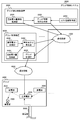
- FIG. 1 is a diagram showing a grid integrated control apparatus 2000 according to the first embodiment together with its use environment.
- the grid integrated control device 2000 controls power transmission between the grids 3000 so as to satisfy the power demand of each grid 3000.
- a solid line arrow represents a data flow
- a dotted line arrow represents a power flow.
- the grid integrated control device 2000 controls at least two or more grids 3000.
- At least one grid 3000 includes a power distribution unit 3030 that distributes power to consumers 7000 that consume power.
- the grid 3000 includes a grid control unit 3020 and a power transmission / reception unit 3050.
- the power transmission / reception unit 3050 performs power transmission to the other grid 3000 and power reception from the other grid 3000.
- the grid 3000 is connected to at least one other grid 3000 via a power transmission line 5000 and can transmit power to each other.
- the grid control unit 3020 controls power transmission / reception by the power transmission / reception unit 3050 in accordance with instructions from the grid integrated control device 2000.
- the power transmission / reception unit 3050 transmits power to the power distribution unit 3030 or another grid 3000.
- power transmission may be performed in the grid 3000 and supply and demand may be adjusted in the grid 3000.
- surplus power is transmitted to other customers 7000 in the grid 3000.
- the method for controlling power transmission between grids described below is also applicable to power transmission in such a grid 3000. By doing so, the power transmission cost in the grid 3000 can be reduced.
- the grid integrated control device 2000 includes a supply / demand power amount information acquisition unit 2030.
- the supply / demand power amount information acquisition unit 2030 acquires power amount information having the supply / demand power amount.
- the supply and demand power amount indicates the difference between the amount of power that the grid 3000 supplies to the other grid 3000 (hereinafter referred to as “supply power amount”) and the amount of power that the grid 3000 supplies from the other grid 3000 (hereinafter referred to as “demand power amount”).
- supply power amount the amount of power that the grid 3000 supplies to the other grid 3000
- demand power amount the amount of power that the grid 3000 supplies from the other grid 3000
- the amount of power is calculated from the total amount of power generated by the power generation in the grid as a result of supply and demand adjustment in the grid.
- the grid integrated control device 2000 includes a cost information acquisition unit 2050.
- the cost information acquisition unit 2050 acquires cost information indicating the cost for power transmission in each transmission line 5000 connecting the grids 3000.
- the grid integrated control device 2000 includes a grid control instruction generation unit 2020.
- the grid control instruction generation unit 2020 determines the transmission power amount between the grids 3000 using the supply / demand power amount information acquired from the supply / demand power amount information acquisition unit 2030 and the cost information acquired from the cost information acquisition unit 2050. That is, based on the difference between the total amount of power supplied to each grid and the total amount of power demand and cost information, the amount of individual transmitted power between the grids is optimized. Specifically, the grid integrated control apparatus 2000 determines the amount of transmitted power between the grids 3000 so as to reduce the total cost of power transmission under the condition that the power demand of each grid 3000 is satisfied. Then, a grid control instruction is transmitted to the grid control unit 3020 to cause the grid 3000 to perform the determined power transmission.
- the transmission of the grid 3000 is controlled so as to reduce the total cost for transmission under the condition that the demand of the grid 3000 is satisfied. To do. Thereby, the cost concerning the power transmission between the grids 3000 can be made small.
- the grid-to-grid power transmission control method described below can also be used to reduce the cost of power transmission in the grid 3000. In this case, power transmission is controlled so as to reduce the power transmission cost based on the difference in the amount of power supply and demand in the grid 3000 and the cost information related to power transmission in the grid 3000.
- Grid 3000 may have a plurality of power distribution units 3030.
- Grid 3000 may have a power generation device that generates electric power.
- the power generation device is, for example, a power generation device that generates power using renewable energy. Specific examples are a solar power generation device and a wind power generation device.
- the grid 3000 may receive power from a conventional power generation facility such as a nuclear power plant. Part or all of the power received by the grid 3000 from the power generation device or the conventional power generation equipment is part or all of the power supplied to the customer 7000 or other grid 3000 in the grid 3000.
- the grid 3000 is connected to at least one other grid 3000 via a power transmission line 5000.
- the communication line 4000 may be constructed in a wired manner, constructed in a wireless manner, or may be constructed by mixing them.
- the grid integrated control device 2000 to perform the process of determining the transmission power amount between the grids 3000. For example, there are a method in which the administrator manually instructs the grid integrated control device 2000 to start the above processing, and a method in which the grid integrated control device 2000 automatically repeats the above processing.
- the power supply / demand information is represented by, for example, a power supply / demand table 100 shown in FIG.
- the supply / demand power amount table 100 includes, for example, a grid ID 102 and a supply / demand power amount 104 representing the supply / demand power amount in the grid 3000 having the ID indicated by the grid ID 102.
- the grid 3000 with the grid ID i is referred to as a grid 3000-i.
- the supply and demand power amount indicates a difference between the power supply amount of the grid 3000 and the demand power amount.
- the supply power amount is larger than the demand power amount
- the demand power amount is greater than the supply power amount.
- the grid 3000-1 is 100 kWh
- the grid 3000-3 is 200 kWh
- the supplied power amount is larger than the demand power amount.
- the demand power amount is 300 kWh higher than the supply power amount.
- Demand-and-supply power amount is determined by, for example, a power sales contract between grid 3000 owners.
- the amount of power supply and demand is determined by a power sales contract between the owner of the power generation device and the customer 7000.
- the supply and demand power amount is, for example, the amount of power generated by the power generation unit 3060 included in the grid 3000 and the amount of power consumed by the customer 7000 receiving power supply from the grid 3000. There is a method to determine from the difference.
- the cost information is represented by a cost table 200 shown in FIG. 3, for example.
- the cost table 200 includes, for example, a grid 1 ID 202 that is an ID of the grid 3000 on one side of the power transmission line 5000, a grid 2 ID 204 that is an ID of the grid 3000 on the other side of the power transmission line 5000, and a grid indicated by the grid 1 ID 202 and the grid 2 ID 204 And a cost 206 indicating the cost for power transmission using the power transmission line 5000 connecting the two.
- the cost 206 indicates, for example, a cost for transmitting 1 W of power through the power transmission line 5000 for 1 hour.
- transmission costs there are various ways to determine transmission costs. For example, there are a method of determining using a consignment fee required for using the power transmission line 5000, a method of determining using a power loss when power is transmitted through the power transmission line 5000, or a method of determining both.
- a method for determining the cost using both the consignment fee and the power loss for example, there is a method in which the consignment fee and the power loss are normalized, and the product of the normalized consignment fee and the normalized power loss is used as the cost.
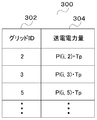
- the grid control instruction transmitted from the grid control instruction generation unit 2020 to the grid control unit 3020 has a combination of a power transmission destination grid 3000 to which the grid 3000 transmits power and a power amount transmitted to the grid 3000.
- This is represented by, for example, the power transmission control table 300 shown in FIG.
- the power transmission control table 300 includes, for example, a grid ID 302 indicating an ID of a grid 3000 as a power transmission destination, and a transmission power amount 304 indicating a transmission power amount transmitted to the grid 3000 indicated by the grid ID 302.
- the method for determining the transmission power amount between the grids is, for example, a method for obtaining transmission power Pl (i, j) that satisfies the linear programming problem 1 expressed by the following mathematical formula 1.
- Pl (i, j) is the magnitude of electric power transmitted from the grid 3000-i to the grid 3000-j.
- Tp the length of time during which the grid 3000 performs power transmission according to the control of the grid integrated control device 2000
- the amount of transmitted power transmitted from the grid 3000-i to the grid 3000-j is expressed as Pl (i, j) ⁇ Tp. Is done.
- Solving the following linear programming problem 1 determines the amount of transmission power that minimizes the cost of power transmission through the transmission line 5000.
- Equation (1) represents an objective function that minimizes the total cost of power transmission between grids.
- W (i, j) represents a cost for transmitting power of magnitude 1 from the grid 3000-i to the grid 3000-j per unit time.
- N represents the total number of grids 3000 controlled by the grid integrated control apparatus 2000.
- Equations (2) and (3) represent the constraints in the linear programming problem 1 described above.
- equation (2) is a constraint condition for satisfying the power demand of the grid 3000-i.
- the difference between the total amount of transmission power transmitted from the grid 3000-i to the other grid 3000-j (that is, the amount of supplied power) and the total amount of received power received from the other grid 3000-j (that is, the amount of demand power) is The supply / demand power amount indicated by the supply / demand power amount 104 of the supply / demand power amount table 100 is obtained.
- Pe (i) represents the power supply / demand amount of the grid 3000-i.
- Equation (3) is a constraint on the magnitude of power transmitted from the grid 3000-i to the grid 3000-j.
- the magnitude of the power transmitted from the grid 3000-i to the grid 3000-j indicates that it is less than or equal to the transmission capacity of the transmission line 5000 connecting the grid 3000-i and the grid 3000-j.
- C (i, j) represents the transmission capacity of the transmission line connecting the grid 3000-i and the grid 3000-j.
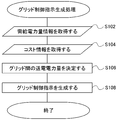
- FIG. 5 shows a flow of grid control instruction generation processing performed by the grid control instruction generation unit 2020.
- the power supply / demand information acquisition unit 2030 acquires power supply / demand information.
- the power supply / demand information There are various methods for acquiring the power supply / demand information. For example, there are a method in which an administrator inputs through an input terminal and a method in which the administrator acquires from the grid 3000.
- step S104 the cost information acquisition unit 2050 acquires cost information.
- Cost information acquired in advance from the owner of each power transmission line 5000 is automatically acquired from a method in which the manager of the grid integrated control device 2000 manually inputs, a database of cost information disclosed by the owner of the power transmission line 5000, or the like. There are methods.
- step S106 the grid control instruction generation unit 2020 determines the transmission power amount between the grids 3000 based on the supply / demand power amount information and the cost information.
- the method is, for example, a method of solving the linear programming problem 1 described above.
- step S108 the above-described grid control instruction is generated from the transmission power amount between the grids 3000 determined in step S106.
- the grid control instruction includes the power transmission control table 300, for example.
- the grid integrated control device 2000 executes grid control instruction generation processing in response to an instruction from the administrator of the grid integrated control apparatus 2000. Further, the grid integrated control apparatus 2000 may execute a grid control instruction generation process in response to a request from the grid 3000. Furthermore, the grid integrated control device 2000 may repeatedly perform grid control instruction generation processing. In this case, for example, the grid integrated control device 2000 performs grid control instruction generation processing at regular time intervals, such as once per hour. The grid integrated control apparatus 2000 may perform the grid control instruction generation process at irregular time intervals such as random time intervals.
- the grid control unit 3020 controls the power transmission / reception unit 3050 in accordance with the grid control instruction received from the grid control instruction generation unit 2020, and transmits power to the other grid 3000 within the Tp time.
- the power transmission control instruction is represented by the power transmission control table 300
- each record of the power transmission control table 300 is referred to, and the power of the power amount indicated by the transmitted power amount 304 is transmitted to the grid 3000 whose ID is the grid ID 302.
- the total cost for power transmission is reduced under the condition that the demand of the grid 3000 is satisfied based on the supply / demand power amount information of each grid 3000 and the cost information of each transmission line 5000.
- the cost for power transmission between the grids 3000 can be reduced.
- FIG. 6 is a diagram showing the grid integrated control apparatus 2000 according to the second embodiment together with its use environment.
- functional blocks to which the same reference numerals as those in FIG. 1 are assigned have the same functions as the functional blocks in FIG.
- the meaning of the arrow is the same as in FIG.
- At least one grid 3000 includes one or more power storage units 3040 that store power.
- the power storage unit 3040 stores the power received from the power transmission / reception unit 3050.
- the power storage unit 3040 transmits the stored power to the power transmission / reception unit 3050.
- the grid control instruction generation unit 2020 includes a power storage information acquisition unit 2040 that acquires power storage information indicating a current power storage amount of the power storage unit 3040. Furthermore, the grid control instruction generation unit 2020 includes an appropriate range information acquisition unit 2070 that acquires appropriate range information indicating an appropriate range of the stored power amount of the power storage unit 3040. The amount of power that can be supplied by the grid 3000 to the customer 7000 and other grids 3000 by setting an appropriate range of the stored power amount of the power storage unit 3040 and keeping the stored power amount of the power storage unit 3040 within this appropriate range. Handle when the number of files increases or decreases unexpectedly. Further, the supply / demand power amount information acquisition unit 2030 in the present embodiment acquires time-series supply / demand power information indicating the supply / demand power amount of each grid 3000 in each time zone of at least two or more time zones.
- generation part 2020 is based on time series supply-and-demand power information, electrical storage information, appropriate range information, and cost information, and the electric power transmission amount between the grids 3000 in each said time slot
- the amount of electric power to be used (hereinafter, charge / discharge electric energy) is determined.
- Grid control instruction generation unit 2020 transmits to grid control unit 3020 a grid control instruction that controls power transmission / reception of power transmission / reception unit 3050 and charge / discharge of power storage unit 3040.
- the grid control unit 3020 controls power transmission by the power transmission / reception unit 3050 in accordance with the power transmission control instruction received from the grid control instruction generation unit 2020.
- Grid control unit 3020 controls charging / discharging of power storage unit 3040 in accordance with the charge / discharge control instruction received from grid control instruction generation unit 2020.
- the power storage unit 3040 when the power storage unit 3040 is used, power is charged to the power storage unit 3040 in a time zone where power is surplus, and power is insufficient even if power is interchanged between the grids 3000 in another time zone.
- By supplying power from the power storage unit 3040 it is possible to solve the power shortage. And it copes with when the electric energy which the grid 3000 can supply to the consumer 7000 and the other grid 3000 unexpectedly increases / decreases by making the electrical storage electric energy of the electrical storage part 3040 into the predetermined appropriate range.
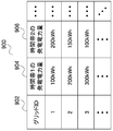
- the time-series supply / demand power amount information indicates the supply / demand power amount of each grid 3000 for each of two or more time zones.
- the time-series supply / demand power amount information is represented by a time-series supply / demand power amount-table 400 shown in FIG.
- the time-series supply / demand power amount table 400 includes, for example, a grid ID 402, supply / demand power amounts in each time zone (supply / demand power amount 404 in time zone 1, supply / demand power amount 406 in time zone 2).
- the power storage information indicates the current power storage amount of the power storage unit 3040.
- the storage information is represented by, for example, a stored power amount table 500 shown in FIG.
- the stored power amount table 500 includes, for example, a grid ID 502 and a power storage unit ID 504 that specify the power storage unit 3040, and a stored power amount 506 indicating the current stored power amount of the power storage unit 3040.
- the appropriate range information indicates an appropriate range of the stored power amount of the power storage unit 3040.
- the amount of power stored in power storage unit 3040 needs to be less than the rated capacity of power storage unit 3040. Furthermore, it is desirable to determine the amount of power stored in power storage unit 3040 on the assumption that the amount of power that grid 3000 can supply to customer 7000 and other grids 3000 unexpectedly increases or decreases. First, it is desirable to set the upper limit value of the stored power amount of the power storage unit 3040 to be smaller than the rated capacity in preparation for the case where the amount of power that can be supplied by the grid 3000 becomes larger than expected and surplus power is generated. Thereby, since the surplus power can be stored in the power storage unit 3040, waste of power can be reduced.
- the appropriate range information is represented by, for example, an appropriate range table 600 shown in FIG.
- the appropriate range table 600 includes, for example, a grid ID 602 and a power storage unit ID 604 for specifying the power storage unit 3040, a lower limit value 606 indicating the lower limit value of the stored power amount of the power storage unit 3040, and an upper limit value 608 indicating the upper limit value.
- the grid control unit 3020 transmits power from the power transmission / reception unit 3050 to the power storage unit 3040 to charge the power storage unit 3040 or discharges power from the power storage unit 3040 according to the grid control instruction received from the grid integrated control device 2000. Power is transmitted to the power transmission / reception unit 3050.
- the grid control instruction has, for example, a charge / discharge control table 700 shown in FIG.
- the charge / discharge control table 700 includes, for example, a charge / discharge power amount 704 that represents the amount of power charged / discharged in the power storage unit 3040 indicated by the power storage unit ID 702 in a certain time period.
- the grid control unit 3020 charges the power storage unit 3040 when the charge / discharge power amount 704 is positive, and discharges the power from the power storage unit 3040 when the charge / discharge power amount 704 is negative.
- a specific method for determining the transmission power amount between the grids 3000 and the charge / discharge power amount of the power storage unit 3040 is, for example, Pl (t, i, j) satisfying the linear programming problem 2 expressed by the following Equation 2. This is a method for obtaining E (t, i, j). Pl (t, i, j) represents the magnitude of electric power transmitted from the grid 3000-i to the grid 3000-j in the time zone t.
- E (t, i, j) represents the amount of power stored in power storage unit 3040 (hereinafter referred to as power storage unit 3040-ij) having power storage unit ID j of grid 3000-i at the start of time period t. .
- the charge / discharge power amount in time zone t is obtained by subtracting the stored power amount E (t, i, j) in time zone t from the stored power amount E (t + 1, i, j) in time zone t + 1.
- Solving the linear programming problem 2 minimizes the cost of power transmission under the condition that the power demand of the grid 3000 is satisfied and the amount of power stored in the power storage unit 3040 is within an appropriate range in all time zones t.
- the transmission power amount between the grids 3000 and the charge / discharge power amount of the power storage unit 3040 are obtained.
- those having the same symbol in the linear programming problem 1 have the same meaning as the symbols in the linear programming problem 1.
- Equation (1) is an objective function that minimizes the total transmission cost, as in the linear programming problem 1.
- Tp in the linear programming problem 2 represents the length of each time zone t.
- Equations (2) to (4) represent the constraints in the above linear programming problem.
- equation (2) is a constraint condition for satisfying the power demand of each grid 3000-i.
- the value obtained by subtracting the total amount of power received by the grid 3000 from the other grids 3000 (that is, the amount of power demand) represents the value of the power supply / demand amount of the grid 3000-i.
- NV (i) represents the total number of power storage units 3040 included in the grid 3000.
- Equation (3) is a constraint condition due to the transmission capacity of the transmission line 5000, similarly to Equation (3) in the first embodiment.
- Equation (4) is a constraint condition indicating that the amount of stored power in the power storage unit 3040 is within an appropriate range.
- LE (i, j) and UE (i, j) represent the lower limit value and the upper limit value of the appropriate range of the stored power amount of the power storage unit 3040-ij, respectively.
- FIG. 11 shows a flow of grid control instruction generation processing in the second embodiment.
- the steps having the same reference numerals in FIG. 5 are assumed to perform the same processing as in FIG.
- step S202 the grid control instruction generation unit 2020 acquires time-series supply / demand power amount information.
- cost information is acquired in step S104.
- step S204 power storage information is acquired.
- step S206 appropriate range information is acquired.
- step S208 the transmission power amount between the grids 3000 and the charge / discharge power amount of the power storage unit 3040 are obtained.
- the specific method is, for example, a method of solving the linear programming problem 2 described above.
- a grid control instruction is generated based on the transmission power amount between the grids 3000 obtained in step S208 and the charge / discharge power amount of the power storage unit 3040.
- the power transmission control table 300 shown in FIG. 4 based on the amount of power transmitted between the grids 3000 is changed to the charge / discharge control table shown in FIG. 10 based on the amount of charge / discharge power of the power storage unit 3040. 700 is generated.
- a table 300 is generated.
- a charge / discharge control table 700 having a record of ⁇ E (t, i, j) ⁇ is generated.
- Grid control unit 3020 controls power transmission / reception unit 3050 and power storage unit 3040 in accordance with the grid control instruction received from grid control instruction generation unit 2020.
- the power transmission control instruction in the present embodiment is represented by the charge / discharge control table 700 and the power transmission control table 300, for example.
- the power transmission process according to the power transmission control table 300 is the same as that of the first embodiment, the description thereof is omitted.
- Grid control unit 3020 refers to each record in charge / discharge control table 700 and charges / discharges power storage unit 3040 having the ID indicated by power storage unit ID 702 within Tp time according to the value of charge / discharge power amount 704. For example, when the value of the charge / discharge power amount 704 is positive, the power of the power amount represented by the value of the charge / discharge power amount 704 is transmitted from the power transmission / reception unit 3050 to the power storage unit 3040 to charge the power storage unit 3040. . On the other hand, when the charge / discharge power amount 704 is a negative value, the power of the amount of power represented by the absolute value of the charge / discharge power amount 704 is discharged from the power storage unit 3040 and transmitted to the power transmission / reception unit 3050. To do.
- the grid control instruction generation unit 2020 may transmit grid control instructions for each of a plurality of time zones at the start of each time zone, or may be transmitted all at once.
- the grid control unit 3020 controls the power transmission / reception unit 3050 and the power storage unit 3040 each time the grid control instruction is received.
- the grid control unit 3020 detects the start of each time zone by monitoring the passage of time, and at the start of each time zone. The power transmission / reception unit 3050 and the power storage unit 3040 are controlled.
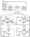
- FIG. 12 is a diagram showing the grid integrated control apparatus 2000 according to the third embodiment together with its use environment.
- functional blocks to which the same reference numerals as those in FIG. 1 or FIG. 6 are assigned have the same functions as the functional blocks described in FIG. 1 or FIG.
- the meaning of the arrow is the same as in FIGS.
- At least one has a power generation unit 3060 that generates electric power.
- the power generation unit 3060 is, for example, a power generation device that generates power using renewable energy. Specific examples are a solar power generation device and a wind power generation device.
- the grid integrated control apparatus 2000 monitors the power generation amount of the power generation unit 3060 and determines an appropriate range of the power storage amount of the power storage unit 3040 according to the power generation amount.
- the grid integrated control device 2000 includes a power generation information acquisition unit 2060 that acquires power generation information representing the amount of power generated by the power generation unit 3060 from the grid 3000.
- the grid integrated control device 2000 also includes a power generation information history storage unit 2100 that stores a power generation information history indicating the amount of power generated by the power generation unit 3060 for each time period.
- the power generation information acquisition unit 2060 stores the acquired power generation amount in the power generation information history storage unit 2100 for each time period.
- the grid control instruction generation unit 2020 further determines an appropriate range of the stored power amount of the power storage unit 3040 based on the power generation information history.
- An appropriate range determination unit 2120 is included.
- a specific method for determining the appropriate range of the amount of power stored in the power storage unit 3040 is, for example, a method of determining based on the increase or decrease in the amount of power generated by the power generation unit 3060.
- the grid control instruction generation unit 2020 can prevent power waste and power shortage by determining an appropriate range of the stored power amount of the power storage unit 3040 based on the generated power amount of the power generation unit 3060.
- the power generation information indicates the amount of power generated by the power generation unit 3060, and is represented by, for example, the generated power amount table 800 illustrated in FIG.
- the generated power amount table 800 includes, for example, a grid ID 802 and a generated power amount 804.
- the grid 3000-i has a plurality of power generation units 3060
- the total power generation amount of the plurality of power generation units 3060 is set as the power generation amount in the grid 3000-i.
- the power generation information acquisition unit 2060 acquires power generation information. For example, there is a method in which an administrator of the grid integrated control device 2000 manually inputs, or a method of obtaining from the power generation unit 3060.
- the power generation information history indicates a history of the power generation amount of the power generation unit 3060 in each time zone, and is represented by, for example, a power generation power history table 900 illustrated in FIG.
- the generated power amount history table 900 includes, for example, a grid ID 902 and a generated power amount for each time zone (a generated power amount 904 in a time zone 1, a generated power amount 906 in a time zone 2, etc.).
- ⁇ Determining the appropriate range> For example, when the power generation amount of the power generation unit 3060 increases, the method of determining the power storage amount of the power storage unit 3040 based on the power generation unit 3060 power generation unit 3060 When the upper limit value of the appropriate range of the stored power amount is reduced and the generated power amount of the power generation unit 3060 is reduced, the lower limit value of the stored power amount of the power storage unit 3040 belonging to the same grid 3000 as the power generation unit 3060 is increased. is there. When the power generation amount of the power generation unit 3060 continues to increase by reducing the power storage amount of the power storage unit 3040 when the power generation amount of the power generation unit 3060 increases, the power generated by the power generation unit 3060 To be stored in 3040.
- the power storage amount of the power storage unit 3040 is increased to increase the power generation amount of the power generation unit 3060. To make up for it. This prevents power shortages.
- FIG. 15 shows a flow of processing in which the appropriate range determination unit 2120 determines the appropriate range of the stored power amount of the power storage unit 3040.
- step S302 the grid IDi is initialized to 1.
- Steps S304 to S314 are loop processing performed for each grid 3000-i.
- step S304 it is determined whether i is equal to or less than the total number of grids. If i is smaller than the total number of grids, the process proceeds to step S306. When i is larger than the total number of grids, the process is finished for all the grids 3000, so the loop process is finished and the appropriate range changing process is finished.
- step S308 based on the record acquired in step S306, it is determined whether the power generation amount of the power generation unit 3060 in the grid 3000-i is increased or decreased. If the amount of generated power is decreasing, the process proceeds to step S310. If the amount of generated power is increasing, the process proceeds to step S312. If there is no increase or decrease in the amount of generated power, the process proceeds to step S314.
- the amount of power generation there are various ways to determine the amount of power generation. For example, when the latest time zone of the power generation information stored in the power generation information history is t, the generated power amount in the time zone t is compared with the generated power amount in the previous time zone t ⁇ 1. There is a way to do it. In addition, for example, there is a method in which a statistical analysis method such as regression analysis is applied to the power generation amount in all time periods to determine the increase / decrease tendency of the power generation amount.
- a statistical analysis method such as regression analysis
- Step S310 is processing when the amount of generated power is decreasing.
- the appropriate range determination unit 2120 increases the lower limit value of the appropriate range of the stored power amount of the power storage unit 3040 included in the grid 3000-i. For example, the appropriate range determination unit 2120 adds a value proportional to the amount of decrease in the amount of generated power to the lower limit value of the appropriate range. Then, the process proceeds to step S314.
- Step S312 is processing when the amount of generated power is increasing.
- the appropriate range determination unit 2120 reduces the upper limit value of the stored power amount appropriate range of the power storage unit 3040 included in the grid 3000-i. For example, the appropriate range determination unit 2120 subtracts a value proportional to the amount of increase in generated power from the upper limit value of the appropriate range. Then, the process proceeds to step S314.
- Step S314 is the end of the loop process starting from Step S304. After increasing the grid IDi by 1, the process returns to step S304.
- step S304 the appropriate range changing process is performed for all the grids 3000.
- the appropriate ranges of all the power storage units 3040 may be changed, or the appropriate ranges of some of the power storage units 3040 may be changed. For example, consider a case where it is determined that the lower limit value of the appropriate range is increased by X for the grid 3000-i having N power storage units 3040. In this case, a method of increasing the lower limit value of the appropriate range of one power storage unit 3040 by X, a method of increasing the lower limit value of the appropriate range of all power storage units 3040 by X / N, and M power storage units out of N There is a method of selecting 3040 and increasing the lower limit value of the appropriate range of the selected power storage unit 3040 by X / M.
- the appropriate range determination unit 2120 performs the appropriate range determination process.
- the appropriate range determination unit 2120 receives the instruction from the administrator of the grid integrated control apparatus 2000 and executes grid control instruction generation processing.
- the appropriate range determination unit 2120 may execute a proper range determination process in response to a request from the grid 3000.
- the appropriate range determination unit 2120 may perform an appropriate range determination process repeatedly. In this case, for example, the appropriate range determination unit 2120 performs the appropriate range determination process at regular time intervals, such as once per hour.
- the appropriate range determination unit 2120 may perform the appropriate range determination process at irregular time intervals such as random time intervals.
- FIG. 16 is a diagram illustrating a grid integrated control apparatus 2000 according to the fourth embodiment, together with its use environment.
- the functional blocks having the same reference numerals as the functional blocks shown in FIG. 1, FIG. 6, or FIG. 12 have the same functions as the functional blocks shown in FIG. 1, FIG. 6, or FIG. The description is omitted.
- the internal configuration of the grid 3000 in FIG. 16 is the same as the internal configuration of the grid 3000 in FIG. 6 or FIG. Therefore, the internal configuration of the grid 3000 is omitted in FIG.
- the grid integrated control apparatus 2000 includes a demand power amount acquisition unit 2160, a supply power amount acquisition unit 2180, and a supply / demand power amount calculation unit 2140.
- the demand power amount acquisition unit 2160 acquires the demand power amount indicating the amount of power that each grid 3000 is supplied from the other grid 3000.
- the supplied power amount acquisition unit 2180 acquires the supplied power amount indicating the amount of power that each grid 3000 supplies to the other grid 3000.
- the supply / demand power amount calculation unit 2140 calculates a supply / demand power amount indicating a difference between the supply power amount acquired from the supply power amount acquisition unit 2180 and the demand power amount acquired from the demand power amount acquisition unit 2160.
- the grid control instruction generation unit 2020 satisfies the power demands of all the grids for which the supply / demand power amounts have been calculated based on the supply / demand power amount calculated by the supply / demand power amount calculation unit 2140 and the cost information acquired by the cost information acquisition unit 2050. Under such conditions, the amount of power transmitted between the grids 3000 is determined so as to reduce the total power transmission cost between the grids 3000.
- the demand power amount acquisition unit 2160 to acquire the demand power amount and the supply power amount acquisition unit 2180 to acquire the supply power amount.
- the amount of power demand and the amount of power supply are based on a sales contract between the power supplier and the power consumer
- a method of acquiring from the external server that manages the sales contract is also conceivable.
- the demand power amount when the demand power amount is determined based on the power amount distributed from the power distribution unit 3030 to the customer 7000, a method of obtaining from the power distribution unit 3030 is also conceivable.
- the power supply amount when the power supply amount is determined based on the power amount generated by the power generation unit 3060, a method of acquiring the power generation amount from the power generation unit 3060 is also conceivable.
- the total cost for power transmission is reduced under the condition that the demand of the grid 3000 is satisfied based on the supply / demand power amount information of each grid 3000 and the cost information of each transmission line 5000.
- the cost for power transmission between the grids 3000 can be reduced.
- the grid integrated control device 2000 since the grid integrated control device 2000 has a function of calculating the power supply / demand amount, there is no need for an administrator or an external device to calculate the power supply / demand amount, and the grid integrated control device 2000 can be used more easily.
- FIG. 17 is a diagram showing a grid control system 8000 according to the fifth embodiment together with its use environment.
- the functional components having the same reference numerals as those in FIG. 1, FIG. 6, or FIG. Further, only one combination of the grid 3000 and the grid control device 6000 is described in order to avoid the figure from becoming complicated.
- the grid control system 8000 includes a grid integrated control device 2000 and two or more grid control devices 6000.
- the grid integrated control device 2000 sets the transmission power amount between the grids 3000 so that the cost for power transmission between the grids 3000 is minimized while satisfying the power demand of the grids 3000 based on the supply and demand power amount information and the cost information. decide.
- the grid integrated control device 2000 obtains supply / demand power amount information from the grid control device 6000.
- the grid integrated control apparatus 2000 transmits a grid control instruction to the grid control apparatus 6000 based on the determined transmission power amount between the grids 3000.
- the grid control device 6000 includes a grid control unit 6020 and controls one grid 3000.
- the grid control unit 6020 controls power transmission by the grid 3000 based on the grid control instruction received from the grid integrated control device 2000.
- Grid control device 6000 includes demand power amount acquisition unit 6040, supply power amount acquisition unit 6060, and supply / demand power amount calculation unit 6080, and calculates the supply / demand power amount from the demand power amount and the supply power amount.
- the demand power amount acquisition unit 6040 acquires the demand power amount of the grid 3000.
- the supplied power amount acquisition unit 6060 acquires the supplied power amount of the grid 3000.
- the supply / demand power amount calculation unit 6080 calculates a supply / demand power amount indicating a difference between the supply power amount acquired by the supply power amount acquisition unit 6060 and the demand power amount acquired by the demand power amount acquisition unit 6040.
- the grid control system 8000 uses the grid control device 6000 to calculate the supply / demand power amount of the grid 3000 and notify the grid integrated control device 2000 of the calculated amount.
- the grid integrated control device 2000 controls the power transmission of the grid 3000 so as to reduce the total cost of power transmission under the condition that the demand of the grid 3000 is satisfied based on the supply and demand power amount and cost information received from the grid control device 6000. By doing, the cost concerning the power transmission between the grids 3000 can be made small.
- the grid control device 6000 and the grid 3000 may be connected by the same communication line 4000 as the communication line 4000 connecting the grid control device 6000 and the grid integrated control device 2000, or may be connected by different communication lines 4000. Good.
- the demand power amount acquisition unit 6040 there are various methods for the demand power amount acquisition unit 6040 to acquire the demand power amount, and the method is the same as the method for the demand power amount acquisition unit 2160 in Embodiment 4 to acquire the demand power amount, for example.
- the supply power amount acquisition unit 6060 there are various methods for the supply power amount acquisition unit 6060 to acquire the supply power amount, and the method is the same as the method for the supply power amount acquisition unit 2180 in Embodiment 4 to acquire the supply power amount, for example.
- the grid control instruction generation unit 2020 generates a grid control instruction for controlling power transmission by the grid 3000.
- the method is, for example, a method for generating a grid control instruction according to the flow shown in FIG. 5, similarly to the grid control instruction generation unit 2020 in the first embodiment.
- the grid control unit 6020 controls power transmission by the grid 3000 based on the grid control instruction received from the grid control instruction generation unit 2020. Specifically, for example, based on the combination of the power transmission destination grid 3000 and the transmission power amount specified by the grid control instruction, the power transmission / reception unit 3050 transmits the power of the transmission power amount to the power transmission destination grid 3000. A control signal for changing the operation of the power transmission / reception unit 3050 is transmitted to the power transmission / reception unit 3050.
- the grid control device 6000 calculates the power supply / demand amount of the grid 3000 and notifies the grid integrated control device 2000, and the grid integrated control device 2000 controls the grid control. Based on the supply and demand power amount received from the device 6000 and the cost information acquired by the cost information acquisition unit 2050, the transmission of the grid 3000 is controlled so as to reduce the total cost for transmission under the condition that the demand of the grid 3000 is satisfied. Thus, the cost for power transmission between the grids 3000 can be reduced.
- a grid integrated control device for controlling a plurality of grids arranged in a distributed manner, The grid is based on a power transmission / reception unit that transmits / receives electric power to / from another grid via a power transmission line, and a control instruction received from the grid integrated control device connected via a communication line.
- Grid control means for controlling the power transmission and reception means At least one of the grids has power distribution means for distributing power to consumers who consume power.
- the grid integrated control device For each of the grids, supply and demand power amount information for obtaining supply and demand power amount information having a supply and demand power amount indicating a difference between the power amount supplied by the grid to the other grid and the power amount supplied from the other grid by the grid.
- Cost information acquisition means for acquiring cost information indicating the cost of power transmission between the grids; Based on the supply and demand power amount information acquired by the supply and demand power amount information acquisition unit and the cost information acquired by the cost information acquisition unit, a combination of the grid of the power transmission source, the grid of the power transmission destination and the transmission power amount is obtained.
- Grid control instruction generating means for determining, generating the control instruction for controlling power transmission by each grid based on the determined combination, and transmitting the control instruction to each grid;
- a grid integrated control device 2.
- the cost indicated by the cost information is determined using a consignment fee for power transmission through the transmission line.
- the cost indicated by the cost information is determined using power loss due to power transmission through the transmission line. Or 2.
- the supply / demand power information acquisition means repeatedly acquires the supply / demand power information
- the grid control instruction generation unit generates and transmits the control instruction each time the supply / demand power amount information acquisition unit acquires the supply / demand power amount information.
- the grid integrated control device has power storage means capable of storing power, and the grid control means performs charge / discharge of the power storage means based on a control instruction received from the grid integrated control device,
- the grid integrated control device Power storage information acquisition means for acquiring power storage information indicating the amount of power stored in the power storage means; Suitable range information acquisition means for acquiring appropriate range information indicating an appropriate range of the stored power amount of the power storage means,
- the supply / demand power amount information has the supply / demand power amount for each of the grids for each of a plurality of time zones
- the grid control instruction generating means includes Obtaining the electricity storage information of the electricity storage means from the electricity storage information obtaining means; Obtaining the appropriate range information of the power storage means from the appropriate range acquisition means; Based on the supply / demand power amount information, the power storage information, and the appropriate range information, the grid of the power transmission source, the grid of the power transmission destination, the combination of power transmission power, and the power storage means are charged and discharged for
- a grid integrated control device that generates the control instruction for controlling power transmission by each grid and charge / discharge by the power storage unit based on the determined combination and transmits the control instruction to each grid. 6). 5.
- the grid integrated control device described, At least one of the grids has power generation means for generating power,
- the grid control device Power generation information acquisition means for acquiring power generation information indicating the amount of power generated by the power generation means; For the grid having both the power storage means and the power generation means, the power generation information is acquired from the power generation information acquisition means for each of two or more time zones, and the power generation information is obtained based on the acquired power generation information.
- An appropriate range determining means for determining an appropriate range of the stored electric energy of the power storage means; A grid integrated control device. 7).
- the appropriate range determining means is provided in the same grid as the power generating means in which the amount of generated power is increased based on the power generation information in the plurality of time zones in determining the appropriate range of the stored power amount.
- the lower limit value of the appropriate range of the stored power amount of the power storage means provided in the same grid as that of the power generation means having the reduced power generation amount is reduced by reducing the upper limit value of the stored power amount of the power storage means.
- Increase 6 The grid integrated control device described. 8). 5.
- the appropriate range determining means repeatedly determines an appropriate range of the stored electric energy. Or 7.
- Demand power amount acquisition means for acquiring a demand power amount indicating the amount of power supplied from the other grid by the grid;
- Supply power amount acquisition means for acquiring a supply power amount indicating the amount of power supplied to the other grid by the grid;
- Supply and demand power amount calculating means for calculating a supply and demand power amount indicating a difference between the demand power amount acquired by the demand power amount acquisition means and the supply power amount acquired by the supply power amount acquisition means;
- the supply / demand power amount information acquisition unit acquires the supply / demand power amount calculated by the supply / demand power amount calculation unit.
- a grid control system having a grid control device and a grid integrated control device that controls the plurality of grid control devices,
- the grid is connected to at least one or more other grids by a power transmission line, and has power transmission / reception means for transmitting and receiving power to and from the other grid via the power transmission line, At least one of the grids has power distribution means for distributing power to consumers who consume power,
- the grid control device Demand power amount acquisition means for acquiring a demand power amount indicating the amount of power supplied from the other grid by the grid; Supply power amount acquisition means for acquiring a supply power amount indicating the amount of power supplied to the other grid by the grid; Supply / demand power amount information having a supply / demand power amount indicating a difference between the supply power amount acquired by the supply power amount acquisition unit and the demand power amount acquired by the demand power amount acquisition unit is generated, to the grid integrated control device Supply and demand power amount information generating means for transmission; Grid control means for controlling the power transmission / reception means in accordance with an instruction from the grid integrated control device connected via a
- Grid control instruction generating means for determining and transmitting an instruction to each of the grid control devices based on the determined combination;
- the cost indicated by the cost information is determined using a consignment fee for power transmission through the transmission line.
- the grid control system described. 12 The cost indicated by the cost information is determined using power loss due to power transmission through the transmission line. Or 11.
- the supply and demand power information generating means repeatedly generates the supply and demand power information,
- the supply and demand power information acquisition unit acquires the supply and demand power amount information each time the supply and demand power amount information generation unit generates the supply and demand power amount information.
- the grid control instruction generation unit generates and transmits the control instruction each time the supply / demand power amount information acquisition unit acquires the supply / demand power amount information.
- a grid control system according to any one of At least one or more of the grids have power storage means capable of storing power, and the grid control means performs charge / discharge of the power storage means based on a control instruction received from the grid integrated control device
- the grid integrated control device includes: Power storage information acquisition means for acquiring power storage information indicating the amount of power stored in the power storage means; Suitable range information acquisition means for acquiring appropriate range information indicating an appropriate range of the stored power amount of the power storage means, The supply / demand power amount information has the supply / demand power amount for each of the grids for each of a plurality of time zones,
- the grid control instruction generating means includes Based on the supply / demand power amount information, the power storage information acquired from the power storage information acquisition means, and the appropriate range information acquired from the appropriate range acquisition means, the grid of the power transmission source and the grid of the power transmission destination for each time zone Determining the amount of power to be charged and discharged by each of the power storage means, The grid control system which produces
- the grid integrated control device includes: Power generation information acquisition means for acquiring power generation information indicating the amount of power generated by the power generation means; For the grid having both the power storage means and the power generation means, the power generation information is acquired from the power generation information acquisition means for each of two or more time zones, and the power generation information is obtained based on the acquired power generation information.
- An appropriate range determining means for determining an appropriate range of the stored electric energy of the power storage means; A grid control system. 16.
- the appropriate range determining means is provided in the same grid as the power generating means in which the amount of generated power is increased based on the power generation information in the plurality of time zones in determining the appropriate range of the stored power amount.
- the lower limit value of the appropriate range of the stored power amount of the power storage means provided in the same grid as that of the power generation means having the reduced power generation amount is reduced by reducing the upper limit value of the stored power amount of the power storage means.
- Increase 15 The grid control system described. 17.
- the appropriate range determining means repeatedly determines an appropriate range of the stored electric energy. Or 16.
- a grid control system having a grid control device that controls a grid and a grid integrated control device that controls the plurality of grid control devices, The grid is connected to the grid integrated control device via a communication line, is connected to at least one other grid with a power transmission line, and is connected to the other grid via the power transmission line.
- Power transmission / reception means for transmitting and receiving power between At least one of the grids has power distribution means for distributing power to consumers who consume power
- the grid control device has grid control means for controlling the power transmission / reception means in accordance with an instruction from the grid integrated control device connected via a communication line
- the grid integrated control device includes: Demand power amount acquisition means for acquiring a demand power amount indicating the amount of power supplied from the other grid by the grid; Supply power amount acquisition means for acquiring a supply power amount indicating the amount of power supplied to the other grid by the grid; Supply / demand power amount calculation means for calculating a supply / demand power amount indicating a difference between the supply power amount acquired by the supply power amount acquisition means and the demand power amount acquired by the demand power amount acquisition means; Cost information acquisition means for acquiring cost information indicating the cost of power transmission between the grids; Based on the supply and demand power amount acquired from the supply and demand power amount calculation means and the cost information acquired from the cost information acquisition means, a combination of the grid of the power transmission source, the grid of the power
- Grid control instruction generating means for transmitting an instruction to each of the grid control devices based on the determined combination;
- a grid control system. 19 The cost indicated by the cost information is determined using a consignment fee for power transmission through the transmission line.
- the grid control system described. 20 The cost indicated by the cost information is determined using power loss due to power transmission through the transmission line. Or 19.
- the grid control system described. 21 The supply and demand power amount calculation means repeatedly calculates the supply and demand power amount and transmits it to the grid integrated control device,
- the grid control instruction generation unit generates and transmits the control instruction each time the grid integrated control apparatus receives the supply and demand electric power.
- a grid control system according to any one of At least one or more of the grids have power storage means capable of storing power, and the grid control means performs charge / discharge of the power storage means based on a control instruction received from the grid integrated control device
- the grid integrated control device includes: Power storage information acquisition means for acquiring power storage information indicating the amount of power stored in the power storage means; Suitable range information acquisition means for acquiring appropriate range information indicating an appropriate range of the stored power amount of the power storage means, The supply / demand power amount information has the supply / demand power amount for each of the grids for each of a plurality of time zones,
- the grid control instruction generating means includes Obtaining the electricity storage information of the electricity storage means from the electricity storage information obtaining means; Obtaining the appropriate range information of the power storage means from the appropriate range acquisition means; Based on the supply / demand power amount, the power storage information, and the appropriate range information, the power transmission source grid, the power transmission destination grid, the combination of the power transmission power amount, and the power charged / discharged by each
- the grid integrated control device includes: Power generation information acquisition means for acquiring power generation information indicating the amount of power generated by the power generation means; For the grid having both the power storage means and the power generation means, the power generation information is acquired from the power generation information acquisition means for each of two or more time zones, and the power generation information is obtained based on the acquired power generation information.
- An appropriate range determining means for determining an appropriate range of the stored electric energy of the power storage means; A grid control system. 24.
- the appropriate range determining means is provided in the same grid as the power generating means in which the amount of generated power is increased based on the power generation information in the plurality of time zones in determining the appropriate range of the stored power amount.
- the lower limit value of the appropriate range of the stored power amount of the power storage means provided in the same grid as that of the power generation means having the reduced power generation amount is reduced by reducing the upper limit value of the stored power amount of the power storage means.
- a grid control device for controlling a grid
- the grid is connected to at least one or more other grids by a power transmission line, and has power transmission / reception means for transmitting and receiving power to and from the other grid via the power transmission line, At least one of the grids has power distribution means for distributing power to consumers who consume power,
- the grid control device Demand power amount acquisition means for acquiring a demand power amount indicating the amount of power supplied from the other grid by the grid; Supply power amount acquisition means for acquiring a supply power amount indicating the amount of power supplied to the other grid by the grid; Supply / demand power amount calculation means for calculating a supply / demand power amount indicating a difference between the supply power amount acquired by the supply power amount acquisition means and the demand power amount acquired by the demand power amount acquisition means;
- the grid that is connected to the grid control device via a communication line and determines a combination of the transmission source grid, the transmission destination grid, and the transmission power amount based on the supply and demand power amount acquired from the grid control device
- Grid control means for controlling the power
- the grid control device transmits an instruction to the grid control device every time the supply / demand power amount is acquired
- the supply and demand power amount calculation means is a grid control device that repeatedly calculates the supply and demand power amount and transmits it to the grid integrated control device.
- Based on the supply / demand power amount information and the cost information, a combination of the grid of the power transmission source, the grid of the power transmission destination and the power transmission power amount is determined, and power transmission by each grid is controlled based on the determined combination.
- the listed program. 30. 28. Or 29. A program as described, At least one or more of the grids have power storage means capable of storing electric power, and the grid control means performs charge / discharge of the power storage means based on a control instruction received from the computer, The program is stored in the computer.
- the ability to determine the amount of power Based on the determined combination, a function of generating the control instruction for controlling the power transmission by each grid and the charge / discharge by the power storage means and transmitting to each grid, A program that gives more. 31. 30.
- a program as described, Having at least one grid, power generation means for generating power The program is stored in the computer.
- the power storage unit provided in the same grid as the power generation unit that has increased the amount of generated power
- the listed program. 33. 32. Provide the computer with a function of repeatedly determining an appropriate range of the stored electric energy Or 32. The program described in. 34.
- Thru 33. The program according to any one of the above. 35.
- a program for giving a grid control system having a grid control device and a grid integrated control device a function of controlling a grid The grid integrated control device and the grid control device are connected via a communication line, The grid is connected to the grid control device via a communication line, is connected to at least one other grid by a power transmission line, and between the other grids via the power transmission line Having power transmission / reception means for transmitting and receiving power,
- the program is In the grid integrated control device, A function of acquiring a demand power amount indicating an amount of power supplied from the other grid by the grid; A function of acquiring a supply power amount indicating an amount of power supplied to the other grid by the grid; A function of calculating a supply and demand power amount indicating a difference between the supply power amount and the demand power amount; A function of acquiring cost information indicating the cost of power transmission between the grids; Based on the supply / demand power amount and the cost information, a combination of the grid of the power transmission source, the grid of the power transmission destination and the power transmission power amount is determined
- the grid integrated control device further has a function of repeatedly calculating the supply and demand power amount and a function of generating and transmitting the control instruction every time the supply and demand power amount is calculated.
- the listed program. 37. 35. Or 36. A program as described, At least one or more of the grids have power storage means capable of storing power, and the grid control means performs charge / discharge of the power storage means based on a control instruction received from the grid integrated control device,
- the program is In the grid integrated control device, A function of acquiring power storage information indicating a stored power amount of the power storage means; A function of acquiring appropriate range information indicating an appropriate range of the amount of stored power of the power storage means; For each of a plurality of time zones, a function of calculating the amount of power supply and demand for each grid, Based on the supply / demand power amount, the power storage information, and the appropriate range information, the power transmission source grid, the power transmission destination grid, the combination of the power transmission power amount, and the power charged / discharged by each power storage unit for
- the grid integrated control device in the determination of the appropriate range of the stored power amount, the grid is provided in the same grid as the power generation means in which the generated power amount is increased based on the power generation information in the plurality of time zones.
- the lower limit value of the appropriate range of the stored power amount of the power storage means provided in the same grid as that of the power generation means having the reduced power generation amount is reduced by reducing the upper limit value of the stored power amount of the power storage means. Further increase the function of increasing 38.
- the grid integrated control system is further provided with a function of repeatedly determining an appropriate range of the stored electric energy 38. Or 39.
- a program for giving a grid control system having a grid control device and a grid integrated control device a function of controlling a grid The grid integrated control device and the grid control device are connected via a communication line, The grid is connected to the grid control device via a communication line, is connected to at least one other grid by a power transmission line, and between the other grids via the power transmission line Having power transmission / reception means for transmitting and receiving power,
- the program is In the grid control device, A function of acquiring a demand power amount indicating an amount of power supplied from the other grid by the grid; A function of acquiring a supply power amount indicating an amount of power supplied to the other grid by the grid; A function of calculating a supply and demand power amount indicating a difference between the supplied power amount and the demand power amount and transmitting the calculated amount to the grid integrated control device; A function of controlling the power transmission / reception means in accordance with an instruction from the grid integrated control device; Hold In the grid integrated control device, A function of acquiring cost information indicating the cost of power transmission between the grid
- the grid control device further has a function of repeatedly calculating the supply and demand power amount and transmitting it to the grid integrated control device, 41.
- the grid integrated control device is further provided with a function of generating and transmitting the control instruction each time the supply / demand power amount is acquired.
- the listed program 43. 41. Or 42.
- a program as described At least one or more of the grids have power storage means capable of storing power, and the grid control means performs charge / discharge of the power storage means based on a control instruction received from the grid integrated control device,
- the program is In the grid integrated control device, A function of acquiring power storage information indicating a stored power amount of the power storage means; A function of acquiring appropriate range information indicating an appropriate range of the amount of stored power of the power storage means; For each of a plurality of time zones, a function of calculating the amount of power supply and demand for each grid, Based on the supply / demand power amount, the power storage information, and the appropriate range information, the power transmission source grid, the power transmission destination grid, the combination of the power transmission power amount, and the power charged / discharged by each power storage unit for each time slot The ability to determine the quantity, Based on the determined combination, a function of transmitting an instruction to control power transmission by the power transmission / reception unit and charge / discharge of the power storage unit to the grid control device; To have more, A program
- the grid integrated control device in the determination of the appropriate range of the stored power amount, the grid is provided in the same grid as the power generation means in which the generated power amount is increased based on the power generation information in the plurality of time zones.
- the lower limit value of the appropriate range of the stored power amount of the power storage means provided in the same grid as that of the power generation means having the reduced power generation amount is reduced by reducing the upper limit value of the stored power amount of the power storage means.
- the grid integrated control system is further provided with a function of repeatedly determining an appropriate range of the stored power amount.
- a program for causing a computer to have a function of operating as a grid control device for controlling a grid The grid is connected to at least one or more other grids by a power transmission line, and has power transmission / reception means for transmitting and receiving power to and from the other grid via the power transmission line,
- the program is stored in the computer.
- the grid that is connected to the grid control device via a communication line and determines a combination of the transmission source grid, the transmission destination grid, and the transmission power amount based on the supply and demand power amount acquired from the grid control device
- the grid integrated control device gives instructions to the computer every time the supply / demand power amount is received from the computer,
- the program is a program for causing the computer to have a function of repeatedly calculating the supply and demand power amount and transmitting the same to the grid integrated control device.
- Controlling power transmission / reception based on a control instruction received from the computer The control method is For each of the grids, obtaining supply and demand power amount information having a supply and demand power amount indicating a difference between the amount of power supplied by the grid to the other grid and the amount of power supplied from the other grid by the grid; Obtaining cost information indicating the cost of power transmission between the grids; Based on the supply / demand power amount information and the cost information, a combination of the grid of the power transmission source, the grid of the power transmission destination and the power transmission power amount is determined, and power transmission by each grid is controlled based on the determined combination. Generating a control instruction and transmitting the control instruction to each of the grids; Control method. 50.
- the control method is: Obtaining power storage information indicating the amount of power stored in the power storage means; Obtaining appropriate range information indicating an appropriate range of the amount of stored power of the power storage means; For each of a plurality of time zones, obtaining the supply / demand power amount information having the supply / demand power amount for each of the grids; Based on the supply / demand power amount information, the power storage information, and the appropriate range information, the grid of the power transmission source, the grid of the power transmission destination, the combination of power transmission power, and the power storage means are charged and discharged for each time zone.
- a control method further comprising: 52. 51.
- the method further comprises a step of reducing the upper limit value of the appropriate range and increasing the lower limit value of the appropriate range of the stored power amount of the power storage unit provided in the same grid as the power generation unit whose generated power amount has decreased. .
- the method further includes the step of repeatedly determining the appropriate range of the stored electric energy. Or 53.
- a grid control system having a plurality of grid control devices and a grid integrated control device is a control method for controlling a grid,
- the grid integrated control device and the grid control device are connected via a communication line,
- the grid is connected to the grid control device via a communication line, is connected to at least one other grid by a power transmission line, and between the other grids via the power transmission line Having power transmission / reception means for transmitting and receiving power,
- the control method is The grid integrated control device obtains a demand power amount indicating an amount of power supplied from the other grid by the grid; and
- the grid integrated control device acquires a supply power amount indicating an amount of power that the grid supplies to another grid; and
- the grid integrated control device calculating a supply and demand power amount indicating a difference between the supply power amount and the demand power amount;
- the grid integrated control device acquires cost information indicating a cost required for power transmission between the grids;
- the grid integrated control device determines a combination of the grid of the power transmission source, the grid of the
- the grid integrated control device repeatedly calculating the supply and demand power amount; and The grid integrated control device generates and transmits the control instruction each time the supply / demand power amount is calculated; 56.
- a control method as described, At least one or more of the grids have power storage means capable of storing power, and the grid control means performs charge / discharge of the power storage means based on a control instruction received from the grid integrated control device,
- the control method is: The grid integrated control device acquiring storage information indicating the amount of stored power of the storage means;
- the grid integrated control device acquires appropriate range information indicating an appropriate range of the stored power amount of the power storage means;
- the grid integrated control device calculates the supply and demand power amount for each of the grids for each of a plurality of time zones;
- the grid integrated control device for each time zone, based on the supply and demand power amount, the storage information and the appropriate range information, the grid of the power transmission source, the grid of the power transmission destination, the combination of
- the lower limit value of the appropriate range of the stored power amount of the power storage means provided in the same grid as that of the power generation means having the reduced power generation amount is reduced by reducing the upper limit value of the stored power amount of the power storage means. 59. further comprising a step of increasing.
- the grid integrated control system further includes a step of repeatedly determining an appropriate range of the stored electric energy. Or 60.
- a grid control system having a grid control device for controlling a grid and a grid integrated control device for controlling a plurality of the grid control devices is a control method for controlling the grid,
- the grid integrated control device and the grid control device are connected via a communication line,
- the grid is connected to the grid control device via a communication line, is connected to at least one other grid by a power transmission line, and between the other grids via the power transmission line Having power transmission / reception means for transmitting and receiving power
- the control method is:
- the grid device acquires a demand power amount indicating an amount of power supplied from the other grid by the grid; and
- the grid device acquires a supply power amount indicating an amount of power that the grid supplies to the other grid; and
- the grid device calculates a supply and demand power amount indicating a difference between the supplied power amount and the demand power amount and transmits the calculated amount to the grid integrated control device;
- the grid integrated control device acquires cost information indicating a cost required for power transmission between the grids;
- the grid control device repeatedly calculating the supply and demand power amount and transmitting it to the grid integrated control device;
- the grid integrated control device generates and transmits the control instruction each time the supply / demand power amount is acquired from the grid control device; 62.
- a control method as described At least one or more of the grids have power storage means capable of storing power, and the grid control means performs charge / discharge of the power storage means based on a control instruction received from the grid integrated control device,
- the control method is The grid integrated control device acquiring storage information indicating the amount of stored power of the storage means;
- the grid integrated control device acquires appropriate range information indicating an appropriate range of the stored power amount of the power storage means;
- the grid control device calculates, for each of a plurality of time zones, the supply and demand power amount for each of the grids, and transmits the calculated amount to the grid integrated control device;
- the grid integrated control device for each time zone, based on the supply and demand power amount, the storage information and the appropriate range information, the grid of the power transmission source, the grid of the power transmission destination, the combination of the transmission power amount, and each of the above Determining the amount of power charged and discharged by the storage means;
- the grid integrated control device based on the determined combination, transmitting to the grid control device an
- a control method as described, At least one of the grids has power generation means for generating power The control method is: The grid integrated control device acquires power generation information indicating the amount of power generated by the power generation means; The grid integrated control apparatus acquires and acquires the power generation information from the power generation information acquisition unit for each of two or more time zones for the grid having both the power storage unit and the power generation unit. Determining an appropriate range of stored power amount of the power storage means based on the power generation information; A control method further comprising: 66.
- the grid integrated control device is provided in the same grid as the power generation means in which the amount of generated power is increased based on the power generation information in the plurality of time zones in determining the appropriate range of the stored power amount.
- the lower limit value of the appropriate range of the stored power amount of the power storage means provided in the same grid as that of the power generation means having the reduced power generation amount is reduced by reducing the upper limit value of the stored power amount of the power storage means. Further comprising a step of increasing 65.
- the grid integrated control system further includes a step of repeatedly determining an appropriate range of the stored electric energy.
- a control method executed by a computer for controlling a grid control device for controlling a grid The grid is connected to at least one or more other grids by a power transmission line, and has power transmission / reception means for transmitting and receiving power to and from the other grid via the power transmission line,
- the control method is Obtaining a demand power amount indicating the amount of power supplied from the other grid by the grid; Obtaining a supply power amount indicating an amount of power supplied by the grid to another grid; Calculating a supply and demand power amount indicating a difference between the supply power amount and the demand power amount;
- the grid control device is connected to the grid control device via a communication line, and based on the supply and demand power amount acquired from the grid control device, a combination of the transmission source grid, the transmission destination grid, and the transmission power amount is determined.
- Control method Following the instruction from the grid integrated control device, controlling the power transmission and reception means; Control method. 69. 68. A control method as described, The grid integrated control device gives instructions to the computer every time the supply / demand power amount is acquired from the computer, The control method further includes a step of repeatedly calculating the supply / demand power amount and transmitting the same to the grid integrated control device.
Landscapes
- Engineering & Computer Science (AREA)
- Power Engineering (AREA)
- General Engineering & Computer Science (AREA)
- Physics & Mathematics (AREA)
- General Physics & Mathematics (AREA)
- Automation & Control Theory (AREA)
- Supply And Distribution Of Alternating Current (AREA)
- Remote Monitoring And Control Of Power-Distribution Networks (AREA)
Abstract
Description
<概要>
図1は、実施形態1に係るグリッド統合制御装置2000を、その使用環境と共に示した図である。グリッド統合制御装置2000は、各グリッド3000の電力需要を満たすように、グリッド3000間における電力の送電を制御する。ここで図1において、実線の矢印はデータの流れを表し、点線の矢印は電力の流れを表す。
グリッド3000は、配電部3030を複数有していてもよい。
需給電力量情報は、例えば図2に示す需給電力量テーブル100によって表される。需給電力量テーブル100は例えば、グリッドID102及び、グリッドID102が示すIDのグリッド3000における需給電力量を表す需給電力量104を有する。以下、グリッドIDがiのグリッド3000を、グリッド3000-iと表記する。需給電力量は、グリッド3000の供給電力量と需要電力量の差を示す。そのため、例えば需給電力量104の値が正の値の場合は供給電力量が需要電力量より多いことを表し、需給電力量104の値が負の値の場合は需要電力量が供給電力量より多いことを表す。例えば図2の場合は、グリッド3000-1は100kWh、グリッド3000-3は200kWh、それぞれ供給電力量が需要電力量より多い。一方グリッド3000-2は、需要電力量が供給電力量より300kWh多い。
コスト情報は、例えば図3に示すコストテーブル200で表される。コストテーブル200は例えば、送電線5000の片側のグリッド3000のIDであるグリッド1ID202、送電線5000のもう一方側のグリッド3000のIDであるグリッド2ID204、及びグリッド1ID202が示すグリッドとグリッド2ID204が示すグリッドを結ぶ送電線5000を利用した送電にかかるコストを示すコスト206を有する。コスト206は例えば、送電線5000を介して1Wの電力を1時間送電するためのコストを示す。
グリッド制御指示生成部2020からグリッド制御部3020へ送信するグリッド制御指示は、グリッド3000が電力を送電する送電先のグリッド3000と、グリッド3000へ送電する電力量の組み合わせを有する。これは、例えば図4に示す送電制御テーブル300で表される。送電制御テーブル300は例えば、送電先のグリッド3000のIDを示すグリッドID302、グリッドID302が示すグリッド3000へ送電する送電電力量を示す送電電力量304を有する。
グリッド間の送電電力量を決定する方法は例えば、以下の数式1で表される線形計画問題1を満たす送電電力Pl(i,j)を求める方法である。ここでPl(i,j)は、グリッド3000-iからグリッド3000-jへ送電する電力の大きさである。グリッド3000がグリッド統合制御装置2000の制御に従って送電を行う時間の長さをTpとすると、グリッド3000-iからグリッド3000-jへ送電する送電電力量は、Pl(i,j)・Tpで表される。下記線形計画問題1を解くことで、送電線5000を介した電力の送電にかかるコストが最小になる送電電力量が定まる。

図5は、グリッド制御指示生成部2020が行う、グリッド制御指示生成処理の流れを示している。
グリッド制御部3020は、グリッド制御指示生成部2020から受信するグリッド制御指示に従って送受電部3050を制御し、Tp時間内に他のグリッド3000へ電力を送電する。送電制御指示が送電制御テーブル300で表される場合、送電制御テーブル300の各レコードを参照し、IDがグリッドID302であるグリッド3000へ、送電電力量304に示される電力量の電力を送電する。
以上の構成により、本実施形態によれば、各グリッド3000の需給電力量情報及び各送電線5000のコスト情報に基づいて、グリッド3000の需要を満たすという条件の下、送電にかかる総コストを小さくするようにグリッド3000の送電を制御することで、グリッド3000間の送電にかかるコストを小さくすることができる。
<概要>
図6は、実施形態2に係るグリッド統合制御装置2000を、その使用環境と共に示した図である。ここで図6において、図1と同符号が割り当てられている機能ブロックは、特に説明しない限り、図1の機能ブロックと同じ機能を有するとし、説明を省略する。また矢印の意味は、図1と同様である。
時系列需給電力量情報は、2つ以上の複数の時間帯それぞれについて、各グリッド3000の需給電力量を示す。時系列需給電力量情報は例えば、図7に示す時系列需給電力量―ブル400で表される。時系列需給電力量テーブル400は例えば、グリッドID402、各時間帯における需給電力量(時間帯1の需給電力量404、時間帯2の需給電力量406など)で構成される。
蓄電情報は、蓄電部3040の現在の蓄電電力量を示す。蓄電情報は例えば、図8に示す蓄電電力量テーブル500で表される。蓄電電力量テーブル500は例えば、蓄電部3040を特定するグリッドID502及び蓄電部ID504、及び蓄電部3040の現在の蓄電電力量を示す蓄電電力量506を有する。
適正範囲情報は、蓄電部3040の蓄電電力量の適正範囲を示す。蓄電部3040の蓄電電力量は、蓄電部3040の定格容量以下である必要がある。さらに蓄電部3040の蓄電電力量は、グリッド3000が需要家7000や他のグリッド3000へ供給できる電力量が予期せず増減する場合を想定して決定することが望ましい。まず、グリッド3000が供給可能な電力量が想定よりも多くなり、余剰電力が発生する場合に備え、蓄電部3040の蓄電電力量の上限値を定格容量よりも小さく設定しておくことが望ましい。これにより、上記余剰電力を蓄電部3040に蓄電することができるため、電力の無駄を少なくできる。そして、グリッド3000が供給可能な電力量が想定よりも少なくなる場合に備えるために、蓄電部3040の蓄電電力量の下限値を設定しておくことが望ましい。こうすることで、グリッド3000が受電する電力だけでは電力が不足する場合に、蓄電部3040から電力を供給することで、電力需要を満たすことができる。
グリッド制御部3020は、グリッド統合制御装置2000から受信するグリッド制御指示に従い、送受電部3050から蓄電部3040へ電力を送電して蓄電部3040を充電し、又は蓄電部3040から電力を放電して送受電部3050へ送電する。グリッド制御指示は例えば図10が示す充放電制御テーブル700を有する。充放電制御テーブル700は例えば、ある時間帯において、蓄電部ID702が示す蓄電部3040に充放電する電力量を表す充放電電力量704を有する。例えばグリッド制御部3020は、充放電電力量704が正の値場合は蓄電部3040へ電力を充電し、充放電電力量704が負の値の場合は蓄電部3040から電力を放電する。
グリッド3000間の送電電力量、及び蓄電部3040の充放電電力量を決定する具体的な方法は例えば、以下の数式2で表される線形計画問題2を満たすPl(t,i,j)及びE(t,i,j)を求める方法である。Pl(t,i,j)は、時間帯tにおいてグリッド3000-iからグリッド3000-jへ送電する電力の大きさを表す。E(t,i,j)は、時間帯tの開始時における、グリッド3000-iが有する蓄電部IDがjの蓄電部3040(以下、蓄電部3040-i-j)の蓄電電力量を表す。時間帯tにおける充放電電力量は、時間帯t+1における蓄電電力量E(t+1,i,j)から、時間帯tにおける蓄電電力量E(t,i,j)を引くことで求まる。線形計画問題2を解くことで、全ての時間帯tにおいて、グリッド3000の電力需要を満たし、かつ蓄電部3040の蓄電電力量を適正範囲内にするという条件の下、送電にかかるコストを最小にするグリッド3000間の送電電力量及び蓄電部3040の充放電電力量が求まる。なお線形計画問題2の各数式中の記号の内、線形計画問題1に同記号のものがあるものは、線形計画問題1における記号と同じ意味を表す。

グリッド制御部3020は、グリッド制御指示生成部2020から受信するグリッド制御指示に従い、送受電部3050と蓄電部3040を制御する。前述したように、本実施形態における送電制御指示は例えば、充放電制御テーブル700と送電制御テーブル300で表される。ここで、送電制御テーブル300に従った送電処理は実施形態1と同様であるため、説明を省略する。
以上の構成から、本実施形態によれば、少なくとも1つ以上のグリッド3000が1つ以上の蓄電部3040を有する場合において、各グリッド3000の電力需要を満たしつつ、さらに全ての蓄電部3040の蓄電電力量が適正範囲内であるという条件も満たした上で、送電にかかるコストを小さくできる。蓄電部3040の蓄電電力量を適正範囲内にすることで、グリッド3000による需要家7000や他のグリッド3000への電力供給が不足することを防ぎ、また、グリッド3000が受電した電力を消費しきれずに電力が無駄になることを防ぐ。
<概要>
図12は、実施形態3に係るグリッド統合制御装置2000を、その使用環境と共に示した図である。ここで図12において、図1又は図6と同符号が割り当てられている機能ブロックは、特に説明しない限り、図1又は図6記載の機能ブロックと同じ機能を有するとし、説明を省略する。また、矢印の意味は図1及び図6と同じである。
発電情報は、発電部3060による発電電力量を示し、例えば図13に示す発電電力量テーブル800で表される。発電電力量テーブル800は例えば、グリッドID802及び発電電力量804を有する。ここで、グリッド3000-iが発電部3060を複数有する場合は例えば、複数の発電部3060の発電電力量の合計を、グリッド3000-iにおける発電電力量とする。
発電情報履歴は、各時間帯における発電部3060の発電電力量の履歴を示し、例えば図14に示す発電電力量履歴テーブル900で表される。発電電力量履歴テーブル900は例えば、グリッドID902、及び時間帯ごとの発電電力量(時間帯1の発電電力量904、時間帯2の発電電力量906など)を有する。
発電部3060の発電電力量に基づいて蓄電部3040の蓄電電力量を決定する方法は例えば、発電部3060の発電電力量が増加した場合は、発電部3060と同じグリッド3000に属する蓄電部3040の蓄電電力量の適正範囲の上限値を小さくし、発電部3060の発電電力量が減少した場合は、発電部3060と同じグリッド3000に属する蓄電部3040の蓄電電力量の下限値を大きくする方法である。発電部3060の発電電力量が増加した場合に蓄電部3040の蓄電電力量を少なくすることで、発電部3060の発電電力量が増加し続けた場合に、発電部3060が発電した電力を蓄電部3040へ蓄えられるようにしておく。こうすることで、発電した電力を消費しきれずに電力の無駄が発生することを防ぐ。また、発電部3060の発電電力量が減少した場合に蓄電部3040の蓄電電力量を多くすることで、発電部3060の発電電力量が減少し続けた場合に、蓄電部3040からより多くの電力を補えるようにしておく。こうすることで、電力不足になることを防ぐ。
図15は、適正範囲決定部2120が蓄電部3040の蓄電電力量の適正範囲を決定する処理の流れを表している。
以上の構成から、本実施形態によれば、少なくとも1つ以上のグリッド3000が1つ以上の蓄電部3040を有する場合において、各グリッド3000の電力需要を満たしつつ、さらに全ての蓄電部3040の蓄電電力量が適正範囲内であるという条件も満たした上で、送電にかかるコストを小さくできる。蓄電部3040の蓄電電力量を適正範囲内にすることで、グリッド3000が電力不足になることを防ぎ、また、発電部3060が発電した電力を蓄えきれずに電力が無駄になることを防ぐ。さらに、発電部3060による発電電力量の変化に追従して蓄電部3040の蓄電電力量の適正範囲を変更することで、発電部3060の発電電力量が予期せず変化した場合に、電力の無駄及び電力不足が発生することを防ぐことができる。
<概要>
図16は、実施形態4に係るグリッド統合制御装置2000を、その使用環境と共に示す図である。ここで図16において、図1、図6又は図12に記載の機能ブロックと同符号の機能ブロックは、特に説明しない限り、図1、図6又は図12に記載の機能ブロックと同様の機能を有するとし、説明を省略する。また、図16におけるグリッド3000の内部構成は例えば、図6又は図12におけるグリッド3000の内部構成と同じである。そのため、図16において、グリッド3000の内部構成は省略する。
需要電力量取得部2160が需要電力量を取得する方法、及び供給電力量取得部2180が供給電力量を取得する方法は様々である。例えば、グリッド統合制御装置2000の管理者が手動で入力する方法がある。また、需要電力量と供給電力量が、電力供給者と電力消費者の間における売買契約に基づくものである場合は、その売買契約を管理する外部のサーバから取得する方法も考えられる。需要電力量については、需要電力量が配電部3030から需要家7000へ配電される電力量に基づいて定められる場合は、配電部3030から取得する方法も考えられる。供給電力量については、供給電力量が発電部3060によって発電される電力量に基づいて定められる場合は、発電部3060から発電電力量を取得する方法も考えられる。
以上の構成により、本実施形態によれば、各グリッド3000の需給電力量情報及び各送電線5000のコスト情報に基づいて、グリッド3000の需要を満たすという条件の下、送電にかかる総コストを小さくするようにグリッド3000の送電を制御することで、グリッド3000間の送電にかかるコストを小さくすることができる。また、グリッド統合制御装置2000が需給電力量を算出する機能を有するため、管理者や外部装置が需給電力量を算出する必要がなくなり、グリッド統合制御装置2000をより容易に利用できるようになる。
<概要>
図17は、実施形態5に係るグリッド制御システム8000をその使用環境と共に示した図である。ここで、図17において図1、図6又は図16と同符号の機能構成部は、それらの図に記載されている同符号の機能構成部と同様の機能を有するため、説明を省略する。また、図が煩雑になることを避けるため、グリッド3000及びグリッド制御装置6000の組み合わせは1つだけ表記する。
以上の構成により、本実施形態によれば、グリッド制御システム8000において、グリッド制御装置6000はグリッド3000の需給電力量を算出してグリッド統合制御装置2000へ通知し、グリッド統合制御装置2000はグリッド制御装置6000から受信した需給電力量とコスト情報取得部2050が取得するコスト情報に基づき、グリッド3000の需要を満たすという条件の下、送電にかかる総コストを小さくするようにグリッド3000の送電を制御することで、グリッド3000間の送電にかかるコストを小さくすることができる。
1. 分散配置された複数のグリッドを制御するグリッド統合制御装置であって、
前記グリッドは、送電線を介して他の前記グリッドとの間で電力の送受電を行う送受電手段と、通信回線を介して接続されている当該グリッド統合制御装置から受信する制御指示に基づいて前記送受電手段を制御するグリッド制御手段を有し、
少なくとも一つの前記グリッドは電力を消費する需要家へ電力を配電する配電手段を有し、
当該グリッド統合制御装置は、
各前記グリッドについて、該グリッドが他の前記グリッドへ供給する電力量と該グリッドが他の前記グリッドから供給される電力量の差を示す需給電力量を有する需給電力量情報を取得する需給電力量情報取得手段と、
前記グリッド間の送電にかかるコストを示すコスト情報を取得するコスト情報取得手段と、
前記需給電力量情報取得手段が取得した前記需給電力量情報と、前記コスト情報取得手段が取得した前記コスト情報に基づいて、送電元の前記グリッド、送電先の前記グリッド及び送電電力量の組み合わせを決定し、決定された組み合わせに基づいて、各前記グリッドによる送電を制御する前記制御指示を生成して、各前記グリッドへ該制御指示を送信するグリッド制御指示生成手段と、
を有するグリッド統合制御装置。
2. 前記コスト情報が示すコストは、前記送電線を通じた電力送電にかかる託送料金を用いて定められている1.記載のグリッド統合制御装置。
3. 前記コスト情報が示すコストは、前記送電線を通じた電力送電による電力損失を用いて定められている1.または2.記載のグリッド統合制御装置。
4. 前記需給電力情報取得手段は、前記需給電力量情報を繰り返し取得し、
前記グリッド制御指示生成手段は、前記需給電力量情報取得手段が前記需給電力量情報を取得する度に、前記制御指示の生成及び送信を行う1.乃至3.いずれか一つ記載のグリッド統合制御装置。
5. 1.乃至4.いずれか一つ記載のグリッド統合制御装置であって、
少なくとも1つ以上の前記グリッドは、電力を蓄電できる蓄電手段を有し、前記グリッド制御手段は、当該グリッド統合制御装置から受信する制御指示に基づいて前記蓄電手段の充放電を行い、
当該グリッド統合制御装置は、
前記蓄電手段の蓄電電力量を示す蓄電情報を取得する蓄電情報取得手段と、
前記蓄電手段の蓄電電力量の適正範囲を示す適正範囲情報を取得する適正範囲情報取得手段と、を有し、
前記需給電力量情報は、複数の時間帯のそれぞれについて、各前記グリッドごとの前記需給電力量を有し、
前記グリッド制御指示生成手段は、
前記蓄電情報取得手段から、前記蓄電手段の前記蓄電情報を取得し、
前記適正範囲取得手段から、前記蓄電手段の前記適正範囲情報を取得し、
前記需給電力量情報、前記蓄電情報及び前記適正範囲情報に基づいて、各時間帯について、送電元の前記グリッド、送電先の前記グリッド、送電電力量の組み合わせ、及び各前記蓄電手段が充放電する電力量を決定し、
決定された組み合わせに基づいて、各前記グリッドによる送電と前記蓄電手段による充放電を制御する前記制御指示を生成して各前記グリッドへ送信するグリッド統合制御装置。
6. 5.記載のグリッド統合制御装置であって、
前記グリッドの少なくとも一つは、電力を発電する発電手段を有し、
前記グリッド制御装置は、
前記発電手段の発電電力量を示す発電情報を取得する発電情報取得手段と、
前記蓄電手段及び前記発電手段の双方を有する前記グリッドについては、2つ以上の複数の時間帯のそれぞれについて、前記発電情報取得手段から前記発電情報を取得し、取得した前記発電情報に基づいて該蓄電手段の蓄電電力量の適正範囲を決定する適正範囲決定手段と、
を有するグリッド統合制御装置。
7. 前記適正範囲決定手段は、前記蓄電電力量の適正範囲の決定において、前記複数の時間帯における前記発電情報に基づいて、発電電力量が増加した前記発電手段と同じ前記グリッドに備えられている前記蓄電手段の蓄電電力量の前記適正範囲の上限値を小さくし、発電電力量が減少した前記発電手段と同じ前記グリッドに備えられている前記蓄電手段の蓄電電力量の前記適正範囲の下限値を大きくする6.記載のグリッド統合制御装置。
8. 前記適正範囲決定手段は、前記蓄電電力量の適正範囲の決定を繰り返し行う6.または7.記載のグリッド統合制御装置。
9. 前記グリッドが他の前記グリッドから供給される電力量を示す需要電力量を取得する需要電力量取得手段と、
前記グリッドが他の前記グリッドへ供給する電力量を示す供給電力量を取得する供給電力量取得手段と、
前記需要電力量取得手段が取得する前記需要電力量と前記供給電力量取得手段が取得する供給電力量の差を示す需給電力量を算出する需給電力量算出手段と、を有し、
前記需給電力量情報取得手段は、前記需給電力量算出手段が算出する前記需給電力量を取得する1.乃至8.いずれか一つ記載のグリッド統合制御装置。
10. グリッド制御装置と、複数の前記グリッド制御装置を制御するグリッド統合制御装置を有するグリッド制御システムであって、
前記グリッドは、少なくとも一つ以上の他の前記グリッドと送電線で接続されており、前記送電線を介して他の前記グリッドとの間で電力の送受電を行う送受電手段を有し、
少なくとも一つの前記グリッドは電力を消費する需要家へ電力を配電する配電手段を有し、
前記グリッド制御装置は、
前記グリッドが他の前記グリッドから供給される電力量を示す需要電力量を取得する需要電力量取得手段と、
前記グリッドが他の前記グリッドへ供給する電力量を示す供給電力量を取得する供給電力量取得手段と、
前記供給電力量取得手段が取得する前記供給電力量と前記需要電力量取得手段が取得する前記需要電力量の差を示す需給電力量を有する需給電力量情報を生成し、前記グリッド統合制御装置へ送信する需給電力量情報生成手段と、
通信回線を介して接続されている前記グリッド統合制御装置からの指示に従い、前記送受電手段を制御するグリッド制御手段と、を有し、
前記グリッド統合制御装置は、
各前記グリッド制御装置から前記需給電力量情報を取得する需給電力量情報取得手段と、
前記グリッド間の送電にかかるコストを示すコスト情報を取得するコスト情報取得手段と、
前記需給電力量情報取得手段が取得する前記需給電力量情報と、前記コスト情報取得手段が取得する前記コスト情報に基づいて、送電元の前記グリッド、送電先の前記グリッド及び送電電力量の組み合わせを決定し、決定された組み合わせに基づいて、各前記グリッド制御装置へ指示を送信するグリッド制御指示生成手段と、
を有するグリッド制御システム。
11. 前記コスト情報が示すコストは、前記送電線を通じた電力送電にかかる託送料金を用いて定められている10.記載のグリッド制御システム。
12. 前記コスト情報が示すコストは、前記送電線を通じた電力送電による電力損失を用いて定められている10.または11.記載のグリッド制御システム。
13. 前記需給電力情報生成手段は、前記需給電力量情報を繰り返し生成し、
前記需給電力情報取得手段は、前記需給電力量情報生成手段が前記需給電力量情報を生成する度に、前記需給電力量情報を取得し、
前記グリッド制御指示生成手段は、前記需給電力量情報取得手段が前記需給電力量情報を取得する度に、前記制御指示の生成及び送信を行う10.乃至12.いずれか一つ記載のグリッド制御システム。
14. 10.乃至13.いずれか一つ記載のグリッド制御システムであって、
少なくとも1つ以上の前記グリッドは、電力を蓄電できる蓄電手段を有し、前記グリッド制御手段は、前記グリッド統合制御装置から受信する制御指示に基づいて前記蓄電手段の充放電を行い、
前記グリッド統合制御装置は、
前記蓄電手段の蓄電電力量を示す蓄電情報を取得する蓄電情報取得手段と、
前記蓄電手段の蓄電電力量の適正範囲を示す適正範囲情報を取得する適正範囲情報取得手段と、を有し、
前記需給電力量情報は、複数の時間帯のそれぞれについて、各前記グリッドごとの前記需給電力量を有し、
前記グリッド制御指示生成手段は、
前記需給電力量情報、前記蓄電情報取得手段から取得する前記蓄電情報及び前記適正範囲取得手段から取得する前記適正範囲情報に基づいて、各時間帯について、送電元の前記グリッド、送電先の前記グリッド、送電電力量の組み合わせ、及び各前記蓄電手段が充放電する電力量を決定し、
決定された組み合わせに基づいて、各前記グリッドによる送電と前記蓄電手段による充放電を制御する前記制御指示を生成して各前記グリッドへ送信するグリッド制御システム。
15. 14.記載のグリッド制御システムであって、
少なくとも一つの前記グリッドは、電力を発電する発電手段を有し、
前記グリッド統合制御装置は、
前記発電手段の発電電力量を示す発電情報を取得する発電情報取得手段と、
前記蓄電手段及び前記発電手段の双方を有する前記グリッドについては、2つ以上の複数の時間帯のそれぞれについて、前記発電情報取得手段から前記発電情報を取得し、取得した前記発電情報に基づいて該蓄電手段の蓄電電力量の適正範囲を決定する適正範囲決定手段と、
を有するグリッド制御システム。
16. 前記適正範囲決定手段は、前記蓄電電力量の適正範囲の決定において、前記複数の時間帯における前記発電情報に基づいて、発電電力量が増加した前記発電手段と同じ前記グリッドに備えられている前記蓄電手段の蓄電電力量の前記適正範囲の上限値を小さくし、発電電力量が減少した前記発電手段と同じ前記グリッドに備えられている前記蓄電手段の蓄電電力量の前記適正範囲の下限値を大きくする15.記載のグリッド制御システム。
17. 前記適正範囲決定手段は、前記蓄電電力量の適正範囲の決定を繰り返し行う15.または16.に記載のグリッド制御システム。
18. グリッドを制御するグリッド制御装置と、複数の前記グリッド制御装置を制御するグリッド統合制御装置を有するグリッド制御システムであって、
前記グリッドは、通信回線を介して前記グリッド統合制御装置と接続されており、少なくとも一つ以上の他の前記グリッドと送電線で接続されており、前記送電線を介して他の前記グリッドとの間で電力の送受電を行う送受電手段を有し、
少なくとも一つの前記グリッドは電力を消費する需要家へ電力を配電する配電手段を有し、
前記グリッド制御装置は、通信回線を介して接続されている前記グリッド統合制御装置からの指示に従い、前記送受電手段を制御するグリッド制御手段を有し、
前記グリッド統合制御装置は、
前記グリッドが他の前記グリッドから供給される電力量を示す需要電力量を取得する需要電力量取得手段と、
前記グリッドが他の前記グリッドへ供給する電力量を示す供給電力量を取得する供給電力量取得手段と、
前記供給電力量取得手段が取得する前記供給電力量と前記需要電力量取得手段が取得する需要電力量の差を示す需給電力量を算出する需給電力量算出手段と、
前記グリッド間の送電にかかるコストを示すコスト情報を取得するコスト情報取得手段と、
前記需給電力量算出手段から取得する前記需給電力量と、前記コスト情報取得手段から取得する前記コスト情報に基づいて、送電元の前記グリッド、送電先の前記グリッド及び送電電力量の組み合わせを決定し、決定された組み合わせに基づいて、各前記グリッド制御装置へ指示を送信するグリッド制御指示生成手段と、
を有するグリッド制御システム。
19. 前記コスト情報が示すコストは、前記送電線を通じた電力送電にかかる託送料金を用いて定められている18.記載のグリッド制御システム。
20. 前記コスト情報が示すコストは、前記送電線を通じた電力送電による電力損失を用いて定められている18.または19.記載のグリッド制御システム。
21. 前記需給電力量算出手段は、前記需給電力量を繰り返し算出して前記グリッド統合制御装置へ送信し、
前記グリッド制御指示生成手段は、前記グリッド統合制御装置が前記需給電力量を受信する度に、前記制御指示の生成及び送信を行う18.乃至20.いずれか一つ記載のグリッド制御システム。
22. 18.乃至21.いずれか一つ記載のグリッド制御システムであって、
少なくとも1つ以上の前記グリッドは、電力を蓄電できる蓄電手段を有し、前記グリッド制御手段は、前記グリッド統合制御装置から受信する制御指示に基づいて前記蓄電手段の充放電を行い、
前記グリッド統合制御装置は、
前記蓄電手段の蓄電電力量を示す蓄電情報を取得する蓄電情報取得手段と、
前記蓄電手段の蓄電電力量の適正範囲を示す適正範囲情報を取得する適正範囲情報取得手段と、を有し、
前記需給電力量情報は、複数の時間帯のそれぞれについて、各前記グリッドごとの前記需給電力量を有し、
前記グリッド制御指示生成手段は、
前記蓄電情報取得手段から、前記蓄電手段の前記蓄電情報を取得し、
前記適正範囲取得手段から、前記蓄電手段の前記適正範囲情報を取得し、
前記需給電力量及び前記蓄電情報及び前記適正範囲情報に基づいて、各時間帯について、送電元の前記グリッド、送電先の前記グリッド、送電電力量の組み合わせ、及び各前記蓄電手段が充放電する電力量を決定し、
決定された組み合わせに基づいて、各前記グリッドによる送電と前記蓄電手段による充放電を制御する前記制御指示を生成して各前記グリッドへ送信するグリッド制御システム。
23. 22.記載のグリッド制御システムであって、
少なくとも一つの前記グリッドは、電力を発電する発電手段を有し、
前記グリッド統合制御装置は、
前記発電手段の発電電力量を示す発電情報を取得する発電情報取得手段と、
前記蓄電手段及び前記発電手段の双方を有する前記グリッドについては、2つ以上の複数の時間帯のそれぞれについて、前記発電情報取得手段から前記発電情報を取得し、取得した前記発電情報に基づいて該蓄電手段の蓄電電力量の適正範囲を決定する適正範囲決定手段と、
を有するグリッド制御システム。
24. 前記適正範囲決定手段は、前記蓄電電力量の適正範囲の決定において、前記複数の時間帯における前記発電情報に基づいて、発電電力量が増加した前記発電手段と同じ前記グリッドに備えられている前記蓄電手段の蓄電電力量の前記適正範囲の上限値を小さくし、発電電力量が減少した前記発電手段と同じ前記グリッドに備えられている前記蓄電手段の蓄電電力量の前記適正範囲の下限値を大きくする23.記載のグリッド制御システム。
25. 前記適正範囲決定手段は、前記蓄電電力量の適正範囲の決定を繰り返し行う23.または24.に記載のグリッド制御システム。
26. グリッドを制御するグリッド制御装置であって、
前記グリッドは、少なくとも一つ以上の他の前記グリッドと送電線で接続されており、前記送電線を介して他の前記グリッドとの間で電力の送受電を行う送受電手段を有し、
少なくとも一つの前記グリッドは電力を消費する需要家へ電力を配電する配電手段を有し、
当該グリッド制御装置は、
前記グリッドが他の前記グリッドから供給される電力量を示す需要電力量を取得する需要電力量取得手段と、
前記グリッドが他の前記グリッドへ供給する電力量を示す供給電力量を取得する供給電力量取得手段と、
前記供給電力量取得手段が取得する前記供給電力量と前記需要電力量取得手段が取得する前記需要電力量の差を示す需給電力量を算出する需給電力量算出手段と、
該グリッド制御装置と通信回線を介して接続されており、該グリッド制御装置から取得する前記需給電力量に基づいて、送信元前記グリッド、送信先前記グリッド、送電電力量の組み合わせを決定する前記グリッド統合制御装置からの指示に従い、前記送受電手段を制御するグリッド制御手段と、
を有するグリッド制御装置。
27. 26.記載のグリッド制御装置であって、
前記グリッド統合制御装置は、前記需給電力量を取得する度に前記グリッド制御装置に指示を送信し、
前記需給電力量算出手段は、前記需給電力量を繰り返し算出して前記グリッド統合制御装置へ送信するグリッド制御装置。
28. コンピュータに、分散配置された複数のグリッドを制御するグリッド統合制御装置として動作する機能を持たせるプログラムであって、
前記グリッドは、少なくとも一つ以上の他の前記グリッドと送電線で接続されており、前記送電線を介して他の前記グリッドとの間で電力の送受電を行い、通信回線を介して接続されている前記コンピュータから受信する制御指示に基づいて前記電力の送受電を制御し、
当該プログラムは、前記コンピュータに、
各前記グリッドについて、該グリッドが他の前記グリッドへ供給する電力量と該グリッドが他の前記グリッドから供給される電力量の差を示す需給電力量を有する需給電力量情報を取得する機能と、
前記グリッド間の送電にかかるコストを示すコスト情報を取得する機能と、
前記需給電力量情報と前記コスト情報に基づいて、送電元の前記グリッド、送電先の前記グリッド及び送電電力量の組み合わせを決定し、決定された組み合わせに基づいて、各前記グリッドによる送電を制御する制御指示を生成して、各前記グリッドへ該制御指示を送信する機能と、
を持たせるプログラム。
29. 前記コンピュータに、
前記需給電力量情報を繰り返し取得する機能と、
前記需給電力量情報を取得する度に、前記制御指示の生成及び送信を行う機能と、
をさらに持たせる28.記載のプログラム。
30. 28.または29.記載のプログラムであって、
少なくとも1つ以上の前記グリッドは、電力を蓄電できる蓄電手段を有し、前記グリッド制御手段は、前記コンピュータから受信する制御指示に基づいて前記蓄電手段の充放電を行い、
前記プログラムは、前記コンピュータに、
前記蓄電手段の蓄電電力量を示す蓄電情報を取得する機能と、
前記蓄電手段の蓄電電力量の適正範囲を示す適正範囲情報を取得する機能と、
複数の時間帯のそれぞれについて、各前記グリッドごとの前記需給電力量を有する、前記需給電力量情報を取得する機能と、
前記需給電力量情報、前記蓄電情報及び前記適正範囲情報に基づいて、各時間帯について、送電元の前記グリッド、送電先の前記グリッド、送電電力量の組み合わせ、及び各前記蓄電手段が充放電する電力量を決定する機能と、
決定された組み合わせに基づいて、各前記グリッドによる送電と前記蓄電手段による充放電を制御する前記制御指示を生成して各前記グリッドへ送信する機能と、
をさらに持たせるプログラム。
31. 30.記載のプログラムであって、
少なくとも一つの前記グリッド、電力を発電する発電手段を有し、
前記プログラムは、前記コンピュータに、
前記発電手段の発電電力量を示す発電情報を取得する機能と、
前記蓄電手段及び前記発電手段の双方を有する前記グリッドについては、2つ以上の複数の時間帯のそれぞれについて、取得した前記発電情報に基づいて該蓄電手段の蓄電電力量の適正範囲を決定する機能と、
をさらに持たせるプログラム。
32. 前記コンピュータに、前記蓄電電力量の適正範囲の決定において、前記複数の時間帯における前記発電情報に基づいて、発電電力量が増加した前記発電手段と同じ前記グリッドに備えられている前記蓄電手段の蓄電電力量の前記適正範囲の上限値を小さくし、発電電力量が減少した前記発電手段と同じ前記グリッドに備えられている前記蓄電手段の蓄電電力量の前記適正範囲の下限値を大きくする機能をさらに持たせる31.記載のプログラム。
33. 前記コンピュータに、前記蓄電電力量の適正範囲の決定を繰り返し行う機能を持たせる31.または32.に記載のプログラム。
34. 前記コンピュータに、
前記グリッドが他の前記グリッドから供給される電力量を示す需要電力量を取得する機能と、
前記グリッドが他の前記グリッドへ供給する電力量を示す供給電力量を取得する機能と、
前記需要電力量と前記供給電力量の差を示す需給電力量を算出する機能と、
をさらに持たせる28.乃至33.いずれか一つに記載のプログラム。
35. グリッド制御装置とグリッド統合制御装置を有するグリッド制御システムに、グリッドを制御する機能を持たせるプログラムであって、
前記グリッド統合制御装置と前記グリッド制御装置は通信回線を介して接続されており、
前記グリッドは通信回線を介して前記グリッド制御装置と接続されており、少なくとも一つ以上の他の前記グリッドと送電線で接続されており、前記送電線を介して他の前記グリッドとの間で電力の送受電を行う送受電手段を有し、
当該プログラムは、
前記グリッド統合制御装置に、
前記グリッドが他の前記グリッドから供給される電力量を示す需要電力量を取得する機能と、
前記グリッドが他の前記グリッドへ供給する電力量を示す供給電力量を取得する機能と、
前記供給電力量と前記需要電力量の差を示す需給電力量を算出する機能と、
前記グリッド間の送電にかかるコストを示すコスト情報を取得する機能と、
前記需給電力量と前記コスト情報に基づいて、送電元の前記グリッド、送電先の前記グリッド及び送電電力量の組み合わせを決定し、決定された組み合わせに基づいて、各前記グリッド制御装置へ指示を送信する機能と、
を持たせ、
前記グリッド制御装置に、前記グリッド統合制御装置からの指示に従い、前記送受電手段を制御する機能を持たせるプログラム。
36. 前記グリッド統合制御装置に、前記需給電力量を繰り返し算出する機能と、前記需給電力量を算出する度に前記制御指示の生成及び送信を行う機能をさらに持たせる35.記載のプログラム。
37. 35.または36.記載のプログラムであって、
少なくとも1つ以上の前記グリッドは、電力を蓄電できる蓄電手段を有し、前記グリッド制御手段は、前記グリッド統合制御装置から受信する制御指示に基づいて前記蓄電手段の充放電を行い、
前記プログラムは、
前記グリッド統合制御装置に、
前記蓄電手段の蓄電電力量を示す蓄電情報を取得する機能と、
前記蓄電手段の蓄電電力量の適正範囲を示す適正範囲情報を取得する機能と、
複数の時間帯のそれぞれについて、各前記グリッドごとの前記需給電力量を算出する機能と、
前記需給電力量及び前記蓄電情報及び前記適正範囲情報に基づいて、各時間帯について、送電元の前記グリッド、送電先の前記グリッド、送電電力量の組み合わせ、及び各前記蓄電手段が充放電する電力量を決定する機能と、
決定された組み合わせに基づいて、前記グリッド制御装置へ、前記送受電手段による送電と前記蓄電手段の充放電を制御する指示を送信する機能と、
をさらに持たせ、
前記グリッド制御装置に、前記指示に従い、前記送受電手段による送電と前記蓄電手段による充放電を制御する機能をさらに持たせるプログラム。
38. 37.記載のプログラムであって、
少なくとも一つの前記グリッドは、電力を発電する発電手段を有し、
前記プログラムは、前記グリッド統合制御装置に、
前記発電手段の発電電力量を示す発電情報を取得する機能と、
前記蓄電手段及び前記発電手段の双方を有する前記グリッドについては、2つ以上の複数の時間帯のそれぞれについて、前記発電情報取得手段から前記発電情報を取得し、取得した前記発電情報に基づいて該蓄電手段の蓄電電力量の適正範囲を決定する機能と、
をさらに持たせるプログラム。
39. 前記グリッド統合制御装置に、前記蓄電電力量の適正範囲の決定において、前記複数の時間帯における前記発電情報に基づいて、発電電力量が増加した前記発電手段と同じ前記グリッドに備えられている前記蓄電手段の蓄電電力量の前記適正範囲の上限値を小さくし、発電電力量が減少した前記発電手段と同じ前記グリッドに備えられている前記蓄電手段の蓄電電力量の前記適正範囲の下限値を大きくする機能をさらに持たせる38.記載のプログラム。
40. 前記グリッド統合制御システムに、前記蓄電電力量の適正範囲の決定を繰り返し行う機能をさらに持たせる38.または39.記載のプログラム。
41. グリッド制御装置とグリッド統合制御装置を有するグリッド制御システムに、グリッドを制御する機能を持たせるプログラムであって、
前記グリッド統合制御装置と前記グリッド制御装置は通信回線を介して接続されており、
前記グリッドは通信回線を介して前記グリッド制御装置と接続されており、少なくとも一つ以上の他の前記グリッドと送電線で接続されており、前記送電線を介して他の前記グリッドとの間で電力の送受電を行う送受電手段を有し、
当該プログラムは、
前記グリッド制御装置に、
前記グリッドが他の前記グリッドから供給される電力量を示す需要電力量を取得する機能と、
前記グリッドが他の前記グリッドへ供給する電力量を示す供給電力量を取得する機能と、
前記供給電力量と前記需要電力量の差を示す需給電力量を算出して前記グリッド統合制御装置に送信する機能と、
前記グリッド統合制御装置からの指示に従い、前記送受電手段を制御する機能と、
を持たせ、
前記グリッド統合制御装置に、
前記グリッド間の送電にかかるコストを示すコスト情報を取得する機能と、
前記需給電力量と前記コスト情報に基づいて、送電元の前記グリッド、送電先の前記グリッド及び送電電力量の組み合わせを決定し、決定された組み合わせに基づいて、各前記グリッド制御装置へ指示を送信する機能と、
を持たせるプログラム。
42. 前記グリッド制御装置に、前記需給電力量を繰り返し算出して前記グリッド統合制御装置に送信する機能をさらに持たせ、
前記グリッド統合制御装置に、前記需給電力量を取得する度に、前記制御指示の生成及び送信を行う機能をさらに持たせる41.記載のプログラム。
43. 41.または42.記載のプログラムであって、
少なくとも1つ以上の前記グリッドは、電力を蓄電できる蓄電手段を有し、前記グリッド制御手段は、前記グリッド統合制御装置から受信する制御指示に基づいて前記蓄電手段の充放電を行い、
前記プログラムは、
前記グリッド統合制御装置に、
前記蓄電手段の蓄電電力量を示す蓄電情報を取得する機能と、
前記蓄電手段の蓄電電力量の適正範囲を示す適正範囲情報を取得する機能と、
複数の時間帯のそれぞれについて、各前記グリッドごとの前記需給電力量を算出する機能と、
前記需給電力量及び前記蓄電情報及び前記適正範囲情報に基づいて、各時間帯について、送電元の前記グリッド、送電先の前記グリッド、送電電力量の組み合わせ、及び各前記蓄電手段が充放電する電力量を決定する機能と、
決定された組み合わせに基づいて、前記グリッド制御装置へ、前記送受電手段による送電と前記蓄電手段の充放電を制御する指示を送信する機能と、
をさらに持たせ、
前記グリッド制御装置に、前記指示に従い、前記送受電手段による送電と前記蓄電手段による充放電を制御する機能をさらに持たせるプログラム。
44. 43.記載のプログラムであって、
少なくとも一つの前記グリッドは、電力を発電する発電手段を有し、
前記プログラムは、前記グリッド統合制御装置に、
前記発電手段の発電電力量を示す発電情報を取得する機能と、
前記蓄電手段及び前記発電手段の双方を有する前記グリッドについては、2つ以上の複数の時間帯のそれぞれについて、前記発電情報取得手段から前記発電情報を取得し、取得した前記発電情報に基づいて該蓄電手段の蓄電電力量の適正範囲を決定する機能と、
をさらに持たせるプログラム。
45. 前記グリッド統合制御装置に、前記蓄電電力量の適正範囲の決定において、前記複数の時間帯における前記発電情報に基づいて、発電電力量が増加した前記発電手段と同じ前記グリッドに備えられている前記蓄電手段の蓄電電力量の前記適正範囲の上限値を小さくし、発電電力量が減少した前記発電手段と同じ前記グリッドに備えられている前記蓄電手段の蓄電電力量の前記適正範囲の下限値を大きくする機能をさらに持たせる44.記載のプログラム。
46. 前記グリッド統合制御システムに、前記蓄電電力量の適正範囲の決定を繰り返し行う機能をさらに持たせる45.記載のプログラム。
47. コンピュータに、グリッドを制御するグリッド制御装置として動作する機能を持たせるプログラムであって、
前記グリッドは、少なくとも一つ以上の他の前記グリッドと送電線で接続されており、前記送電線を介して他の前記グリッドとの間で電力の送受電を行う送受電手段を有し、
当該プログラムは、前記コンピュータに、
前記グリッドが他の前記グリッドから供給される電力量を示す需要電力量を取得する機能と、
前記グリッドが他の前記グリッドへ供給する電力量を示す供給電力量を取得する機能と、
前記供給電力量と前記需要電力量の差を示す需給電力量を算出する機能と、
該グリッド制御装置と通信回線を介して接続されており、該グリッド制御装置から取得する前記需給電力量に基づいて、送信元前記グリッド、送信先前記グリッド、送電電力量の組み合わせを決定する前記グリッド統合制御装置からの指示に従い、前記送受電手段を制御する機能と、
を持たせるプログラム。
48. 47.記載のプログラムであって、
前記グリッド統合制御装置は、前記コンピュータから前記需給電力量を受信するたびに前記コンピュータに指示を行い、
前記プログラムは、前記コンピュータに、前記需給電力量を繰り返し算出して前記グリッド統合制御装置へ送信する機能を持たせるプログラム。
49. 分散配置された複数のグリッドを制御するコンピュータによって実行される制御方法であって、
前記グリッドは、少なくとも一つ以上の他の前記グリッドと送電線で接続されており、前記送電線を介して他の前記グリッドとの間で電力の送受電を行い、通信回線を介して接続されている前記コンピュータから受信する制御指示に基づいて前記電力の送受電を制御し、
当該制御方法は、
各前記グリッドについて、該グリッドが他の前記グリッドへ供給する電力量と該グリッドが他の前記グリッドから供給される電力量の差を示す需給電力量を有する需給電力量情報を取得するステップと、
前記グリッド間の送電にかかるコストを示すコスト情報を取得するステップと、
前記需給電力量情報と前記コスト情報に基づいて、送電元の前記グリッド、送電先の前記グリッド及び送電電力量の組み合わせを決定し、決定された組み合わせに基づいて、各前記グリッドによる送電を制御する制御指示を生成して、各前記グリッドへ該制御指示を送信するステップと、
を有する制御方法。
50. 前記需給電力量情報を繰り返し取得するステップと、
前記需給電力量情報を取得する度に、前記制御指示の生成及び送信を行うステップと、
をさらに有する49.記載の制御方法。
51. 49.または50.記載の制御方法であって、
少なくとも1つ以上の前記グリッドは、電力を蓄電できる蓄電手段を有し、前記グリッド制御手段は、前記コンピュータから受信する制御指示に基づいて前記蓄電手段の充放電を行い、
前記制御方法は、
前記蓄電手段の蓄電電力量を示す蓄電情報を取得するステップと、
前記蓄電手段の蓄電電力量の適正範囲を示す適正範囲情報を取得するステップと、
複数の時間帯のそれぞれについて、各前記グリッドごとの前記需給電力量を有する前記需給電力量情報を取得するステップと、
前記需給電力量情報、前記蓄電情報及び前記適正範囲情報に基づいて、各時間帯について、送電元の前記グリッド、送電先の前記グリッド、送電電力量の組み合わせ、及び各前記蓄電手段が充放電する電力量を決定するステップと、
決定された組み合わせに基づいて、各前記グリッドによる送電と前記蓄電手段による充放電を制御する前記制御指示を生成して各前記グリッドへ送信するステップと、
をさらに有する制御方法。
52. 51.記載の制御方法であって、
少なくとも一つの前記グリッドは、電力を発電する発電手段を有し、
前記制御手段は、
前記発電手段の発電電力量を示す発電情報を取得するステップと、
前記蓄電手段及び前記発電手段の双方を有する前記グリッドについては、2つ以上の複数の時間帯のそれぞれについて、取得した前記発電情報に基づいて該蓄電手段の蓄電電力量の適正範囲を決定するステップと、
をさらに有する制御方法。
53. 前記蓄電電力量の適正範囲の決定において、前記複数の時間帯における前記発電情報に基づいて、発電電力量が増加した前記発電手段と同じ前記グリッドに備えられている前記蓄電手段の蓄電電力量の前記適正範囲の上限値を小さくし、発電電力量が減少した前記発電手段と同じ前記グリッドに備えられている前記蓄電手段の蓄電電力量の前記適正範囲の下限値を大きくするステップをさらに有する52.記載の制御方法。
54. 前記蓄電電力量の適正範囲の決定を繰り返し行うステップをさらに有する52.または53.に記載の制御方法。
55. 前記グリッドが他の前記グリッドから供給される電力量を示す需要電力量を取得するステップと、
前記グリッドが他の前記グリッドへ供給する電力量を示す供給電力量を取得するステップと、
前記需要電力量と前記供給電力量の差を示す需給電力量を算出するステップと、
をさらに有する49.乃至54.いずれか一つに記載の制御方法。
56. 複数のグリッド制御装置と、グリッド統合制御装置を有するグリッド制御システムが、グリッドを制御する制御方法であって、
前記グリッド統合制御装置と前記グリッド制御装置は通信回線を介して接続されており、
前記グリッドは通信回線を介して前記グリッド制御装置と接続されており、少なくとも一つ以上の他の前記グリッドと送電線で接続されており、前記送電線を介して他の前記グリッドとの間で電力の送受電を行う送受電手段を有し、
当該制御方法は、
前記グリッド統合制御装置が、前記グリッドが他の前記グリッドから供給される電力量を示す需要電力量を取得するステップと、
前記グリッド統合制御装置が、前記グリッドが他の前記グリッドへ供給する電力量を示す供給電力量を取得するステップと、
前記グリッド統合制御装置が、前記供給電力量と前記需要電力量の差を示す需給電力量を算出するステップと、
前記グリッド統合制御装置が、前記グリッド間の送電にかかるコストを示すコスト情報を取得するステップと、
前記グリッド統合制御装置が、前記需給電力量と前記コスト情報に基づいて、送電元の前記グリッド、送電先の前記グリッド及び送電電力量の組み合わせを決定し、決定された組み合わせに基づいて、各前記グリッド制御装置へ指示を送信するステップと、
前記グリッド制御装置が、前記グリッド統合制御装置からの指示に従い、前記送受電手段を制御するステップと、
を有する制御方法。
57. 前記グリッド統合制御装置が、前記需給電力量を繰り返し算出するステップと、
前記グリッド統合制御装置が、前記需給電力量を算出する度に、前記制御指示の生成及び送信を行うステップと、
を有する56.記載の制御方法。
58. 56.または57.記載の制御方法であって、
少なくとも1つ以上の前記グリッドは、電力を蓄電できる蓄電手段を有し、前記グリッド制御手段は、前記グリッド統合制御装置から受信する制御指示に基づいて前記蓄電手段の充放電を行い、
前記制御方法は、
前記グリッド統合制御装置が、前記蓄電手段の蓄電電力量を示す蓄電情報を取得するステップと、
前記グリッド統合制御装置が、前記蓄電手段の蓄電電力量の適正範囲を示す適正範囲情報を取得するステップと、
前記グリッド統合制御装置が、複数の時間帯のそれぞれについて、各前記グリッドごとの前記需給電力量を算出するステップと、
前記グリッド統合制御装置が、前記需給電力量及び前記蓄電情報及び前記適正範囲情報に基づいて、各時間帯について、送電元の前記グリッド、送電先の前記グリッド、送電電力量の組み合わせ、及び各前記蓄電手段が充放電する電力量を決定するステップと、
前記グリッド統合制御装置が、決定された組み合わせに基づいて、前記グリッド制御装置へ、前記送受電手段による送電と前記蓄電手段の充放電を制御する指示を送信するステップと、
前記グリッド制御装置が、前記指示に従い、前記送受電手段による送電と前記蓄電手段による充放電を制御するステップと、
を有する制御方法。
59. 58.記載の制御方法であって、
少なくとも一つの前記グリッドは、電力を発電する発電手段を有し、
前記制御方法は、
前記グリッド統合制御装置が、前記発電手段の発電電力量を示す発電情報を取得するステップと、
前記グリッド統合制御装置が、前記蓄電手段及び前記発電手段の双方を有する前記グリッドについては、2つ以上の複数の時間帯のそれぞれについて、前記発電情報取得手段から前記発電情報を取得し、取得した前記発電情報に基づいて該蓄電手段の蓄電電力量の適正範囲を決定するステップと、
をさらに有する制御方法。
60. 前記グリッド統合制御装置が、前記蓄電電力量の適正範囲の決定において、前記複数の時間帯における前記発電情報に基づいて、発電電力量が増加した前記発電手段と同じ前記グリッドに備えられている前記蓄電手段の蓄電電力量の前記適正範囲の上限値を小さくし、発電電力量が減少した前記発電手段と同じ前記グリッドに備えられている前記蓄電手段の蓄電電力量の前記適正範囲の下限値を大きくするステップをさらに有する59.記載の制御方法。
61. 前記グリッド統合制御システムが、前記蓄電電力量の適正範囲の決定を繰り返し行うステップをさらに有する59.または60.記載の制御方法。
62. グリッドを制御するグリッド制御装置と、複数の前記グリッド制御装置を制御するグリッド統合制御装置を有するグリッド制御システムが、前記グリッドを制御する制御方法であって、
前記グリッド統合制御装置と前記グリッド制御装置は通信回線を介して接続されており、
前記グリッドは通信回線を介して前記グリッド制御装置と接続されており、少なくとも一つ以上の他の前記グリッドと送電線で接続されており、前記送電線を介して他の前記グリッドとの間で電力の送受電を行う送受電手段を有し、
前記制御方法は、
前記グリッド装置が、前記グリッドが他の前記グリッドから供給される電力量を示す需要電力量を取得するステップと、
前記グリッド装置が、前記グリッドが他の前記グリッドへ供給する電力量を示す供給電力量を取得するステップと、
前記グリッド装置が、前記供給電力量と前記需要電力量の差を示す需給電力量を算出して前記グリッド統合制御装置に送信するステップと、
前記グリッド統合制御装置が、前記グリッド間の送電にかかるコストを示すコスト情報を取得するステップと、
前記グリッド統合制御装置が、前記需給電力量と前記コスト情報に基づいて、送電元の前記グリッド、送電先の前記グリッド及び送電電力量の組み合わせを決定し、決定された組み合わせに基づいて、各前記グリッド制御装置へ指示を送信するステップと、
前記グリッド制御装置が、前記グリッド統合制御装置からの指示に従い、前記送受電手段を制御するステップと、
を有する制御方法。
63. 前記グリッド制御装置が、前記需給電力量を繰り返し算出して前記グリッド統合制御装置に送信するステップと、
前記グリッド統合制御装置が、前記グリッド制御装置から前記需給電力量を取得する度に、前記制御指示の生成及び送信を行うステップと、
を有する62.記載の制御方法。
64. 61.または62.記載の制御方法であって、
少なくとも1つ以上の前記グリッドは、電力を蓄電できる蓄電手段を有し、前記グリッド制御手段は、前記グリッド統合制御装置から受信する制御指示に基づいて前記蓄電手段の充放電を行い、
当該制御方法は、
前記グリッド統合制御装置が、前記蓄電手段の蓄電電力量を示す蓄電情報を取得するステップと、
前記グリッド統合制御装置が、前記蓄電手段の蓄電電力量の適正範囲を示す適正範囲情報を取得するステップと、
前記グリッド制御装置が、複数の時間帯のそれぞれについて、各前記グリッドごとの前記需給電力量を算出して前記グリッド統合制御装置へ送信するステップと、
前記グリッド統合制御装置が、前記需給電力量及び前記蓄電情報及び前記適正範囲情報に基づいて、各時間帯について、送電元の前記グリッド、送電先の前記グリッド、送電電力量の組み合わせ、及び各前記蓄電手段が充放電する電力量を決定するステップと、
前記グリッド統合制御装置が、決定された組み合わせに基づいて、前記グリッド制御装置へ、前記送受電手段による送電と前記蓄電手段の充放電を制御する指示を送信するステップと、
前記グリッド制御装置が、前記指示に従い、前記送受電手段による送電と前記蓄電手段による充放電を制御するステップと、
を有する制御方法。
65. 64.記載の制御方法であって、
少なくとも一つの前記グリッドは、電力を発電する発電手段を有し、
前記制御方法は、
前記グリッド統合制御装置が、前記発電手段の発電電力量を示す発電情報を取得するステップと、
前記グリッド統合制御装置が、前記蓄電手段及び前記発電手段の双方を有する前記グリッドについては、2つ以上の複数の時間帯のそれぞれについて、前記発電情報取得手段から前記発電情報を取得し、取得した前記発電情報に基づいて該蓄電手段の蓄電電力量の適正範囲を決定するステップと、
をさらに有する制御方法。
66. 前記グリッド統合制御装置が、前記蓄電電力量の適正範囲の決定において、前記複数の時間帯における前記発電情報に基づいて、発電電力量が増加した前記発電手段と同じ前記グリッドに備えられている前記蓄電手段の蓄電電力量の前記適正範囲の上限値を小さくし、発電電力量が減少した前記発電手段と同じ前記グリッドに備えられている前記蓄電手段の蓄電電力量の前記適正範囲の下限値を大きくするステップをさらに有する65.記載の制御方法。
67. 前記グリッド統合制御システムが、前記蓄電電力量の適正範囲の決定を繰り返し行うステップをさらに有する62.乃至66.いずれか一つに記載の制御方法。
68. グリッドを制御するグリッド制御装置を制御するコンピュータによって実行される制御方法であって、
前記グリッドは、少なくとも一つ以上の他の前記グリッドと送電線で接続されており、前記送電線を介して他の前記グリッドとの間で電力の送受電を行う送受電手段を有し、
当該制御方法は、
前記グリッドが他の前記グリッドから供給される電力量を示す需要電力量を取得するステップと、
前記グリッドが他の前記グリッドへ供給する電力量を示す供給電力量を取得するステップと、
前記供給電力量と前記需要電力量の差を示す需給電力量を算出するステップと、
前記該グリッド制御装置と通信回線を介して接続されており、該グリッド制御装置から取得する前記需給電力量に基づいて、送信元前記グリッド、送信先前記グリッド、送電電力量の組み合わせを決定する前記グリッド統合制御装置からの指示に従い、前記送受電手段を制御するステップと、
を有する制御方法。
69. 68.記載の制御方法であって、
前記グリッド統合制御装置は、前記コンピュータから前記需給電力量を取得する度に、前記コンピュータに指示を行い、
前記制御方法は、前記需給電力量を繰り返し算出して前記グリッド統合制御装置へ送信するステップをさらに有する制御方法。
Claims (14)
- 分散配置された複数のグリッドを制御するグリッド統合制御装置であって、
前記グリッドは、送電線を介して他の前記グリッドとの間で電力の送受電を行う送受電手段と、通信回線を介して接続されている当該グリッド統合制御装置から受信する制御指示に基づいて前記送受電手段を制御するグリッド制御手段を有し、
前記グリッドの少なくとも一つは電力を消費する需要家へ電力を配電する配電手段を有し、
当該グリッド統合制御装置は、
各前記グリッドについて、該グリッドが他の前記グリッドへ供給する電力量と該グリッドが他の前記グリッドから供給される電力量の差を示す需給電力量を有する需給電力量情報を取得する需給電力量情報取得手段と、
前記グリッド間の送電にかかるコストを示すコスト情報を取得するコスト情報取得手段と、
前記需給電力量情報取得手段が取得した前記需給電力量情報と、前記コスト情報取得手段が取得した前記コスト情報に基づいて、送電元の前記グリッド、送電先の前記グリッド及び送電電力量の組み合わせを決定し、決定された組み合わせに基づいて、各前記グリッドによる送電を制御する前記制御指示を生成して、各前記グリッドへ該制御指示を送信するグリッド制御指示生成手段と、
を有するグリッド統合制御装置。 - 前記コスト情報が示すコストは、前記送電線を通じた電力送電にかかる託送料金を用いて定められている請求項1記載のグリッド統合制御装置。
- 前記コスト情報が示すコストは、前記送電線を通じた電力送電による電力損失を用いて定められている請求項1または2に記載のグリッド統合制御装置。
- 前記需給電力量情報取得手段は、前記需給電力量情報を繰り返し取得し、
前記グリッド制御指示生成手段は、前記需給電力量情報取得手段が前記需給電力量情報を取得する度に、前記制御指示の生成及び送信を行う請求項1乃至3いずれか一項記載のグリッド統合制御装置。 - 請求項1乃至4いずれか一項に記載のグリッド統合制御装置であって、
少なくとも1つ以上の前記グリッドは、電力を蓄電できる蓄電手段を有し、前記グリッド制御手段は、前記グリッド統合制御装置から受信する制御指示に基づいて前記蓄電手段の充放電を行い、
当該グリッド統合制御装置は、
前記蓄電手段の蓄電電力量を示す蓄電情報を取得する蓄電情報取得手段と、
前記蓄電手段の蓄電電力量の適正範囲を示す適正範囲情報を取得する適正範囲情報取得手段と、を有し、
前記需給電力量情報は、複数の時間帯のそれぞれについて、各前記グリッドごとの前記需給電力量を有し、
前記グリッド制御指示生成手段は、
前記蓄電情報取得手段から、前記蓄電手段の前記蓄電情報を取得し、
前記適正範囲取得手段から、前記蓄電手段の前記適正範囲情報を取得し、
前記需給電力量情報、前記蓄電情報及び前記適正範囲情報に基づいて、各時間帯について、送電元の前記グリッド、送電先の前記グリッド、送電電力量の組み合わせ、及び各前記蓄電手段が充放電する電力量を決定し、
決定された組み合わせに基づいて、各前記グリッドによる送電と前記蓄電手段による充放電を制御する前記制御指示を生成して各前記グリッドへ送信するグリッド統合制御装置。 - 請求項5記載のグリッド統合制御装置であって、
前記グリッドの少なくとも一つは電力を発電する発電手段を有し、
当該グリッド統合制御装置は、
前記発電手段の発電電力量を示す発電情報を取得する発電情報取得手段と、
前記蓄電手段及び前記発電手段の双方を有する前記グリッドについては、2つ以上の複数の時間帯のそれぞれについて、前記発電情報取得手段から前記発電情報を取得し、取得した前記発電情報に基づいて該蓄電手段の蓄電電力量の適正範囲を決定する適正範囲決定手段と、
を有するグリッド統合制御装置。 - 前記適正範囲決定手段は、前記蓄電電力量の適正範囲の決定において、前記複数の時間帯における前記発電情報に基づいて、発電電力量が増加した前記発電手段と同じ前記グリッドに備えられている前記蓄電手段の蓄電電力量の前記適正範囲の上限値を小さくし、発電電力量が減少した前記発電手段と同じ前記グリッドに備えられている前記蓄電手段の蓄電電力量の前記適正範囲の下限値を大きくする請求項6記載のグリッド統合制御装置。
- 前記適正範囲決定手段は、前記蓄電電力量の適正範囲の決定を繰り返し行う請求項6または7に記載のグリッド統合制御装置。
- 前記グリッドが他の前記グリッドから供給される電力量を示す需要電力量を取得する需要電力量取得手段と、
前記グリッドが他の前記グリッドへ供給する電力量を示す供給電力量を取得する供給電力量取得手段と、
前記需要電力量取得手段が取得する前記需要電力量と前記供給電力量取得手段が取得する供給電力量の差を示す需給電力量を算出する需給電力量算出手段と、を有し、
前記需給電力量情報取得手段は、前記需給電力量算出手段が算出する前記需給電力量を有する前記需給電力量情報を取得する請求項1乃至8いずれか一項に記載のグリッド統合制御装置。 - グリッド制御装置と、複数の前記グリッド制御装置を制御するグリッド統合制御装置を有するグリッド制御システムであって、
前記グリッドは、少なくとも一つ以上の他の前記グリッドと送電線で接続されており、前記送電線を介して他の前記グリッドとの間で電力の送受電を行う送受電手段を有し、
少なくとも一つの前記グリッドは電力を消費する需要家へ電力を配電する配電手段を有し、
前記グリッド制御装置は、
前記グリッドが他の前記グリッドから供給される電力量を示す需要電力量を取得する需要電力量取得手段と、
前記グリッドが他の前記グリッドへ供給する電力量を示す供給電力量を取得する供給電力量取得手段と、
前記供給電力量取得手段が取得する前記供給電力量と前記需要電力量取得手段が取得する前記需要電力量の差を示す需給電力量を有する需給電力量情報を生成し、前記グリッド統合制御装置へ送信する需給電力量情報生成手段と、
通信回線を介して接続されている前記グリッド統合制御装置からの指示に従い、前記送受電手段を制御するグリッド制御手段と、を有し、
前記グリッド統合制御装置は、
各前記グリッド制御装置から前記需給電力量情報を取得する需給電力量情報取得手段と、
前記グリッド間の送電にかかるコストを示すコスト情報を取得するコスト情報取得手段と、
前記需給電力量情報取得手段が取得する前記需給電力量情報と、前記コスト情報取得手段が取得する前記コスト情報に基づいて、送電元の前記グリッド、送電先の前記グリッド及び送電電力量の組み合わせを決定し、決定された組み合わせに基づいて、各前記グリッド制御装置へ指示を送信するグリッド制御指示生成手段と、
を有するグリッド制御システム。 - グリッドを制御するグリッド制御装置と、複数の前記グリッド制御装置を制御するグリッド統合制御装置を有するグリッド制御システムであって、
前記グリッドは、通信回線を介して前記グリッド統合制御装置と接続されており、少なくとも一つ以上の他の前記グリッドと送電線で接続されており、前記送電線を介して他の前記グリッドとの間で電力の送受電を行う送受電手段を有し、少なくとも一つの前記グリッドは電力を消費する需要家へ電力を配電する配電手段を有し、
前記グリッド制御装置は、通信回線を介して接続されている前記グリッド統合制御装置からの指示に従い、前記送受電手段を制御するグリッド制御手段を有し、
前記グリッド統合制御装置は、
前記グリッドが他の前記グリッドから供給される電力量を示す需要電力量を取得する需要電力量取得手段と、
前記グリッドが他の前記グリッドへ供給する電力量を示す供給電力量を取得する供給電力量取得手段と、
前記供給電力量取得手段が取得する前記供給電力量と前記需要電力量取得手段が取得する前記需要電力量の差を示す需給電力量を算出する需給電力量算出手段と、
前記グリッド間の送電にかかるコストを示すコスト情報を取得するコスト情報取得手段と、
前記需給電力量算出手段から取得する前記需給電力量と、前記コスト情報取得手段から取得する前記コスト情報に基づいて、送電元の前記グリッド、送電先の前記グリッド及び送電電力量の組み合わせを決定し、決定された組み合わせに基づいて、各前記グリッド制御装置へ前記指示を送信するグリッド制御指示生成手段と、
を有するグリッド制御システム。 - グリッドを制御するグリッド制御装置であって、
前記グリッドは、少なくとも一つ以上の他の前記グリッドと送電線で接続されており、前記送電線を介して他の前記グリッドとの間で電力の送受電を行う送受電手段を有し、
少なくとも一つの前記グリッドは電力を消費する需要家へ電力を配電する配電手段を有し、
当該グリッド制御装置は、
前記グリッドが他の前記グリッドから供給される電力量を示す需要電力量を取得する需要電力量取得手段と、
前記グリッドが他の前記グリッドへ供給する電力量を示す供給電力量を取得する供給電力量取得手段と、
前記供給電力量取得手段が取得する前記供給電力量と前記需要電力量取得手段が取得する前記需要電力量の差を示す需給電力量を算出する需給電力量算出手段と、
該グリッド制御装置と通信回線を介して接続されており、該グリッド制御装置から取得する前記需給電力量に基づいて、送信元の前記グリッド、送信先の前記グリッド、送電電力量の組み合わせを決定する前記グリッド統合制御装置からの指示に従い、前記送受電手段を制御するグリッド制御手段と、
を有するグリッド制御装置。 - コンピュータに、分散配置された複数のグリッドを制御するグリッド統合制御装置として動作する機能を持たせるプログラムであって、
前記グリッドは、少なくとも一つ以上の他の前記グリッドと送電線で接続されており、前記送電線を介して他の前記グリッドとの間で電力の送受電を行い、通信回線を介して接続されている前記コンピュータから受信する制御指示に基づいて前記電力の送受電を制御し、
前記プログラムは、前記コンピュータに、
各前記グリッドについて、該グリッドが他の前記グリッドへ供給する電力量と該グリッドが他の前記グリッドから供給される電力量の差を示す需給電力量を有する需給電力量情報を取得する機能と、
前記グリッド間の送電にかかるコストを示すコスト情報を取得する機能と、
前記需給電力量情報と前記コスト情報に基づいて、送電元の前記グリッド、送電先の前記グリッド及び送電電力量の組み合わせを決定し、決定された組み合わせに基づいて、各前記グリッドによる送電を制御する制御指示を生成して、各前記グリッドへ該制御指示を送信する機能と、
を持たせるプログラム。 - 分散配置された複数のグリッドを制御するコンピュータによって実行される制御方法であって、
前記グリッドは、少なくとも一つ以上の他の前記グリッドと送電線で接続されており、前記送電線を介して他の前記グリッドとの間で電力の送受電を行い、通信回線を介して接続されている前記コンピュータから受信する制御指示に基づいて前記電力の送受電を制御し、
当該制御方法は、
各前記グリッドについて、該グリッドが他の前記グリッドへ供給する電力量と該グリッドが他の前記グリッドから供給される電力量の差を示す需給電力量を有する需給電力量情報を取得するステップと、
前記グリッド間の送電にかかるコストを示すコスト情報を取得するステップと、
前記需給電力量情報と前記コスト情報に基づいて、送電元の前記グリッド、送電先の前記グリッド及び送電電力量の組み合わせを決定し、決定された組み合わせに基づいて、各前記グリッドによる送電を制御する制御指示を生成して、各前記グリッドへ該制御指示を送信するステップと、
を有する制御方法。
Priority Applications (3)
| Application Number | Priority Date | Filing Date | Title |
|---|---|---|---|
| EP13826414.8A EP2882071B1 (en) | 2012-07-30 | 2013-04-16 | Grid integrated control device, grid control system, grid control device, program, and control method |
| US14/418,278 US10193339B2 (en) | 2012-07-30 | 2013-04-16 | Grid integrated control apparatus, grid control system, grid control apparatus, program, and control method |
| JP2014528019A JP6187463B2 (ja) | 2012-07-30 | 2013-04-16 | グリッド統合制御装置、グリッド制御システム、グリッド制御装置、プログラム、及び制御方法 |
Applications Claiming Priority (2)
| Application Number | Priority Date | Filing Date | Title |
|---|---|---|---|
| JP2012-168250 | 2012-07-30 | ||
| JP2012168250 | 2012-07-30 |
Publications (1)
| Publication Number | Publication Date |
|---|---|
| WO2014020951A1 true WO2014020951A1 (ja) | 2014-02-06 |
Family
ID=50027646
Family Applications (1)
| Application Number | Title | Priority Date | Filing Date |
|---|---|---|---|
| PCT/JP2013/061322 Ceased WO2014020951A1 (ja) | 2012-07-30 | 2013-04-16 | グリッド統合制御装置、グリッド制御システム、グリッド制御装置、プログラム、及び制御方法 |
Country Status (4)
| Country | Link |
|---|---|
| US (1) | US10193339B2 (ja) |
| EP (1) | EP2882071B1 (ja) |
| JP (1) | JP6187463B2 (ja) |
| WO (1) | WO2014020951A1 (ja) |
Cited By (8)
| Publication number | Priority date | Publication date | Assignee | Title |
|---|---|---|---|---|
| JP2016046884A (ja) * | 2014-08-21 | 2016-04-04 | 三菱電機株式会社 | 広域系統制御装置 |
| US9837819B2 (en) | 2014-05-27 | 2017-12-05 | Nec Corporation | Power network system, power control method, power router, control apparatus, and storage medium |
| JP2020503826A (ja) * | 2016-12-30 | 2020-01-30 | ヴォッベン プロパティーズ ゲーエムベーハーWobben Properties Gmbh | 配電ネットワークの制御方法 |
| JP2023016577A (ja) * | 2021-07-21 | 2023-02-02 | 日新電機株式会社 | マイクログリッドの需給制御装置及びマイクログリッドの需給制御方法 |
| JP7448268B1 (ja) | 2022-09-07 | 2024-03-12 | イーエヌ テクノロジーズ インク. | エネルギー貯蔵システムおよびその動作方法 |
| JP2024042683A (ja) * | 2022-09-15 | 2024-03-28 | イーエヌ テクノロジーズ インク. | エネルギー貯蔵システムおよびその動作方法 |
| JP7670252B1 (ja) * | 2024-04-17 | 2025-04-30 | Jfeスチール株式会社 | エネルギー運用支援システム、情報処理装置、情報出力装置、エネルギー運用装置、エネルギー運用支援方法およびエネルギー運用方法 |
| WO2025220255A1 (ja) * | 2024-04-17 | 2025-10-23 | Jfeスチール株式会社 | エネルギー運用支援システム、情報処理装置、情報出力装置、エネルギー運用装置、エネルギー運用支援方法およびエネルギー運用方法 |
Families Citing this family (14)
| Publication number | Priority date | Publication date | Assignee | Title |
|---|---|---|---|---|
| WO2014167830A1 (ja) * | 2013-04-09 | 2014-10-16 | 日本電気株式会社 | 電力制御システム |
| EP2894597A1 (en) * | 2014-01-10 | 2015-07-15 | Alcatel Lucent | A method and device for controlling a power grid |
| US9378461B1 (en) | 2014-09-26 | 2016-06-28 | Oracle International Corporation | Rule based continuous drift and consistency management for complex systems |
| US20170077714A1 (en) * | 2015-09-10 | 2017-03-16 | Cpg Technologies, Llc | Flexible network topology and bidirectional power flow |
| US9703340B1 (en) * | 2015-12-18 | 2017-07-11 | International Business Machines Corporation | Intermittently redistributing energy from multiple power grids in a data center context |
| KR20190033620A (ko) * | 2016-08-09 | 2019-03-29 | 엠에이치아이 베스타스 오프쇼어 윈드 에이/에스 | 풍력 터빈 제어 방법 및 시스템 |
| WO2018168053A1 (ja) * | 2017-03-17 | 2018-09-20 | 日本電気株式会社 | 電力管理装置、電力管理方法、及び、プログラム |
| KR20180121079A (ko) | 2017-04-28 | 2018-11-07 | 엘에스산전 주식회사 | 계층형 전력 제어 시스템 |
| US10700521B2 (en) | 2017-04-28 | 2020-06-30 | Lsis Co., Ltd. | Hierarchical type power control system |
| WO2019107806A1 (ko) * | 2017-11-28 | 2019-06-06 | 엘에스산전 주식회사 | 계층형 전력 제어 시스템 |
| US10795690B2 (en) * | 2018-10-30 | 2020-10-06 | Oracle International Corporation | Automated mechanisms for ensuring correctness of evolving datacenter configurations |
| US10892961B2 (en) | 2019-02-08 | 2021-01-12 | Oracle International Corporation | Application- and infrastructure-aware orchestration for cloud monitoring applications |
| US20230216339A1 (en) * | 2021-12-31 | 2023-07-06 | Duke Energy Corporation | Systems and methods for differential power generation |
| US20230369878A1 (en) * | 2022-05-13 | 2023-11-16 | Franklinwh Technologies Co., Ltd. | Household energy storage system in an off-grid state and black start method therefor |
Citations (7)
| Publication number | Priority date | Publication date | Assignee | Title |
|---|---|---|---|---|
| JP2001309559A (ja) | 2000-04-21 | 2001-11-02 | Toshiba Corp | エネルギー設備運用計画装置 |
| JP2007143364A (ja) * | 2005-11-22 | 2007-06-07 | Osaka Gas Co Ltd | 電力グリッドシステム |
| WO2009072453A1 (ja) * | 2007-12-03 | 2009-06-11 | Meidensha Corporation | 電力系統の制御システムおよび制御方法 |
| JP2010213420A (ja) * | 2009-03-09 | 2010-09-24 | Toshiba Corp | 電力融通管理システムおよび電力融通管理プログラム |
| JP2011061931A (ja) | 2009-09-08 | 2011-03-24 | Toshiba Corp | スマートグリッド及びマイクログリッド向け総合監視制御システム |
| JP4783453B2 (ja) | 2009-09-10 | 2011-09-28 | 力也 阿部 | 多端子型非同期連系装置、電力機器制御端末装置と電力ネットワークシステムおよびその制御方法 |
| JP2012168250A (ja) | 2011-02-10 | 2012-09-06 | Ims:Kk | 写真シール払出装置およびその制御方法 |
Family Cites Families (10)
| Publication number | Priority date | Publication date | Assignee | Title |
|---|---|---|---|---|
| JP2007143362A (ja) * | 2005-11-22 | 2007-06-07 | Sanyo Electric Co Ltd | モータ制御回路 |
| CA2749770C (en) * | 2009-01-14 | 2021-07-20 | Integral Analytics, Inc. | Optimization of microgrid energy use and distribution |
| US8401709B2 (en) * | 2009-11-03 | 2013-03-19 | Spirae, Inc. | Dynamic distributed power grid control system |
| JP2011101534A (ja) * | 2009-11-06 | 2011-05-19 | Panasonic Electric Works Co Ltd | 電力融通システム |
| JP5822434B2 (ja) * | 2010-02-04 | 2015-11-24 | オムロン株式会社 | 電力需給システム、グリーン電力供給制御装置、グリーン電力受領制御装置、グリーン電力需給証明装置、精算システム、移動体、グリーン電力需給システム、グリーン電力送受電方法、グリーン電力需給証明方法、および、精算方法 |
| US20120029720A1 (en) * | 2010-07-29 | 2012-02-02 | Spirae, Inc. | Dynamic distributed power grid control system |
| US9225173B2 (en) * | 2011-09-28 | 2015-12-29 | Causam Energy, Inc. | Systems and methods for microgrid power generation and management |
| US9163828B2 (en) * | 2011-10-31 | 2015-10-20 | Emerson Process Management Power & Water Solutions, Inc. | Model-based load demand control |
| US9261869B2 (en) * | 2012-02-13 | 2016-02-16 | Emerson Process Management Power & Water Solutions, Inc. | Hybrid sequential and simultaneous process simulation system |
| US9563215B2 (en) * | 2012-07-14 | 2017-02-07 | Causam Energy, Inc. | Method and apparatus for actively managing electric power supply for an electric power grid |
-
2013
- 2013-04-16 US US14/418,278 patent/US10193339B2/en not_active Expired - Fee Related
- 2013-04-16 EP EP13826414.8A patent/EP2882071B1/en not_active Not-in-force
- 2013-04-16 WO PCT/JP2013/061322 patent/WO2014020951A1/ja not_active Ceased
- 2013-04-16 JP JP2014528019A patent/JP6187463B2/ja active Active
Patent Citations (7)
| Publication number | Priority date | Publication date | Assignee | Title |
|---|---|---|---|---|
| JP2001309559A (ja) | 2000-04-21 | 2001-11-02 | Toshiba Corp | エネルギー設備運用計画装置 |
| JP2007143364A (ja) * | 2005-11-22 | 2007-06-07 | Osaka Gas Co Ltd | 電力グリッドシステム |
| WO2009072453A1 (ja) * | 2007-12-03 | 2009-06-11 | Meidensha Corporation | 電力系統の制御システムおよび制御方法 |
| JP2010213420A (ja) * | 2009-03-09 | 2010-09-24 | Toshiba Corp | 電力融通管理システムおよび電力融通管理プログラム |
| JP2011061931A (ja) | 2009-09-08 | 2011-03-24 | Toshiba Corp | スマートグリッド及びマイクログリッド向け総合監視制御システム |
| JP4783453B2 (ja) | 2009-09-10 | 2011-09-28 | 力也 阿部 | 多端子型非同期連系装置、電力機器制御端末装置と電力ネットワークシステムおよびその制御方法 |
| JP2012168250A (ja) | 2011-02-10 | 2012-09-06 | Ims:Kk | 写真シール払出装置およびその制御方法 |
Non-Patent Citations (1)
| Title |
|---|
| See also references of EP2882071A4 |
Cited By (11)
| Publication number | Priority date | Publication date | Assignee | Title |
|---|---|---|---|---|
| US9837819B2 (en) | 2014-05-27 | 2017-12-05 | Nec Corporation | Power network system, power control method, power router, control apparatus, and storage medium |
| JP2016046884A (ja) * | 2014-08-21 | 2016-04-04 | 三菱電機株式会社 | 広域系統制御装置 |
| JP2020503826A (ja) * | 2016-12-30 | 2020-01-30 | ヴォッベン プロパティーズ ゲーエムベーハーWobben Properties Gmbh | 配電ネットワークの制御方法 |
| JP2023016577A (ja) * | 2021-07-21 | 2023-02-02 | 日新電機株式会社 | マイクログリッドの需給制御装置及びマイクログリッドの需給制御方法 |
| JP7736992B2 (ja) | 2021-07-21 | 2025-09-10 | 日新電機株式会社 | マイクログリッドの需給制御装置及びマイクログリッドの需給制御方法 |
| JP7448268B1 (ja) | 2022-09-07 | 2024-03-12 | イーエヌ テクノロジーズ インク. | エネルギー貯蔵システムおよびその動作方法 |
| JP2024037709A (ja) * | 2022-09-07 | 2024-03-19 | イーエヌ テクノロジーズ インク. | エネルギー貯蔵システムおよびその動作方法 |
| JP2024042683A (ja) * | 2022-09-15 | 2024-03-28 | イーエヌ テクノロジーズ インク. | エネルギー貯蔵システムおよびその動作方法 |
| JP7534827B2 (ja) | 2022-09-15 | 2024-08-15 | イーエヌ テクノロジーズ インク. | エネルギー貯蔵システムおよびその動作方法 |
| JP7670252B1 (ja) * | 2024-04-17 | 2025-04-30 | Jfeスチール株式会社 | エネルギー運用支援システム、情報処理装置、情報出力装置、エネルギー運用装置、エネルギー運用支援方法およびエネルギー運用方法 |
| WO2025220255A1 (ja) * | 2024-04-17 | 2025-10-23 | Jfeスチール株式会社 | エネルギー運用支援システム、情報処理装置、情報出力装置、エネルギー運用装置、エネルギー運用支援方法およびエネルギー運用方法 |
Also Published As
| Publication number | Publication date |
|---|---|
| JPWO2014020951A1 (ja) | 2016-07-21 |
| EP2882071A1 (en) | 2015-06-10 |
| EP2882071A4 (en) | 2016-04-27 |
| US20150214737A1 (en) | 2015-07-30 |
| JP6187463B2 (ja) | 2017-08-30 |
| EP2882071B1 (en) | 2017-08-16 |
| US10193339B2 (en) | 2019-01-29 |
Similar Documents
| Publication | Publication Date | Title |
|---|---|---|
| JP6187463B2 (ja) | グリッド統合制御装置、グリッド制御システム、グリッド制御装置、プログラム、及び制御方法 | |
| US10509374B2 (en) | Systems and methods for managing power generation and storage resources | |
| EP2408082A1 (en) | Integrated demand response for energy utilization | |
| JP6629673B2 (ja) | 電力託送制御システム | |
| CN113424386A (zh) | 能源管理系统及其控制方法 | |
| JP6334785B2 (ja) | 電力管理システム、電力管理方法、及び制御装置 | |
| WO2017170018A1 (ja) | 電力制御装置、電力制御方法、およびプログラム | |
| EP3598379A1 (en) | Power management device, power management method, and program | |
| US11621563B2 (en) | System for dynamic demand balancing in energy networks | |
| JP2016134933A (ja) | エネルギー管理システム、コンピュータプログラム及び運転計画の算出方法 | |
| JP2004040956A (ja) | 電力供給管理方法 | |
| WO2013179809A1 (ja) | 電力管理装置、電力管理システム、及び電力管理方法 | |
| KR101983836B1 (ko) | 가상 발전소 플랫폼에 기반한 에너지 관리 시스템 및 그 관리 방법 | |
| TWI650728B (zh) | 微電網多代理日前市場排程方法 | |
| JP2017050911A (ja) | 運転計画の算出装置、算出方法及びコンピュータプログラム | |
| JP4508748B2 (ja) | 自家発電装置集中管理システム | |
| US11128145B2 (en) | System for controlling energy supply across multiple generation sites | |
| JP2005135266A (ja) | 電力取引支援システム | |
| JP6855934B2 (ja) | サーバ装置、電力管理システム、及びコンピュータプログラム | |
| JP4617290B2 (ja) | 発電計画システム | |
| CN102346452B (zh) | 用于能量利用的综合需求响应 | |
| JP2023158872A (ja) | 分散型電源システム | |
| JP2016063719A (ja) | 給電システム、電力使用対価算出装置、給電方法、電力使用対価算出方法及びプログラム |
Legal Events
| Date | Code | Title | Description |
|---|---|---|---|
| 121 | Ep: the epo has been informed by wipo that ep was designated in this application |
Ref document number: 13826414 Country of ref document: EP Kind code of ref document: A1 |
|
| ENP | Entry into the national phase |
Ref document number: 2014528019 Country of ref document: JP Kind code of ref document: A |
|
| REEP | Request for entry into the european phase |
Ref document number: 2013826414 Country of ref document: EP |
|
| WWE | Wipo information: entry into national phase |
Ref document number: 2013826414 Country of ref document: EP |
|
| WWE | Wipo information: entry into national phase |
Ref document number: 14418278 Country of ref document: US |
|
| NENP | Non-entry into the national phase |
Ref country code: DE |