WO2014020979A1 - インクジェット記録装置及び印字制御方法 - Google Patents
インクジェット記録装置及び印字制御方法 Download PDFInfo
- Publication number
- WO2014020979A1 WO2014020979A1 PCT/JP2013/064813 JP2013064813W WO2014020979A1 WO 2014020979 A1 WO2014020979 A1 WO 2014020979A1 JP 2013064813 W JP2013064813 W JP 2013064813W WO 2014020979 A1 WO2014020979 A1 WO 2014020979A1
- Authority
- WO
- WIPO (PCT)
- Prior art keywords
- ink
- printing
- particles
- recording apparatus
- ink particles
- Prior art date
- Legal status (The legal status is an assumption and is not a legal conclusion. Google has not performed a legal analysis and makes no representation as to the accuracy of the status listed.)
- Ceased
Links
Images


Classifications
-
- B—PERFORMING OPERATIONS; TRANSPORTING
- B41—PRINTING; LINING MACHINES; TYPEWRITERS; STAMPS
- B41J—TYPEWRITERS; SELECTIVE PRINTING MECHANISMS, i.e. MECHANISMS PRINTING OTHERWISE THAN FROM A FORME; CORRECTION OF TYPOGRAPHICAL ERRORS
- B41J2/00—Typewriters or selective printing mechanisms characterised by the printing or marking process for which they are designed
- B41J2/005—Typewriters or selective printing mechanisms characterised by the printing or marking process for which they are designed characterised by bringing liquid or particles selectively into contact with a printing material
- B41J2/01—Ink jet
- B41J2/015—Ink jet characterised by the jet generation process
- B41J2/04—Ink jet characterised by the jet generation process generating single droplets or particles on demand
- B41J2/045—Ink jet characterised by the jet generation process generating single droplets or particles on demand by pressure, e.g. electromechanical transducers
- B41J2/04501—Control methods or devices therefor, e.g. driver circuits, control circuits
- B41J2/04576—Control methods or devices therefor, e.g. driver circuits, control circuits controlling heads of electrostatic type
-
- B—PERFORMING OPERATIONS; TRANSPORTING
- B41—PRINTING; LINING MACHINES; TYPEWRITERS; STAMPS
- B41J—TYPEWRITERS; SELECTIVE PRINTING MECHANISMS, i.e. MECHANISMS PRINTING OTHERWISE THAN FROM A FORME; CORRECTION OF TYPOGRAPHICAL ERRORS
- B41J2/00—Typewriters or selective printing mechanisms characterised by the printing or marking process for which they are designed
- B41J2/005—Typewriters or selective printing mechanisms characterised by the printing or marking process for which they are designed characterised by bringing liquid or particles selectively into contact with a printing material
- B41J2/01—Ink jet
- B41J2/015—Ink jet characterised by the jet generation process
- B41J2/02—Ink jet characterised by the jet generation process generating a continuous ink jet
-
- B—PERFORMING OPERATIONS; TRANSPORTING
- B05—SPRAYING OR ATOMISING IN GENERAL; APPLYING FLUENT MATERIALS TO SURFACES, IN GENERAL
- B05B—SPRAYING APPARATUS; ATOMISING APPARATUS; NOZZLES
- B05B12/00—Arrangements for controlling delivery; Arrangements for controlling the spray area
- B05B12/08—Arrangements for controlling delivery; Arrangements for controlling the spray area responsive to condition of liquid or other fluent material to be discharged, of ambient medium or of target ; responsive to condition of spray devices or of supply means, e.g. pipes, pumps or their drive means
- B05B12/12—Arrangements for controlling delivery; Arrangements for controlling the spray area responsive to condition of liquid or other fluent material to be discharged, of ambient medium or of target ; responsive to condition of spray devices or of supply means, e.g. pipes, pumps or their drive means responsive to conditions of ambient medium or target, e.g. humidity, temperature position or movement of the target relative to the spray apparatus
- B05B12/126—Arrangements for controlling delivery; Arrangements for controlling the spray area responsive to condition of liquid or other fluent material to be discharged, of ambient medium or of target ; responsive to condition of spray devices or of supply means, e.g. pipes, pumps or their drive means responsive to conditions of ambient medium or target, e.g. humidity, temperature position or movement of the target relative to the spray apparatus responsive to target velocity, e.g. to relative velocity between spray apparatus and target
-
- B—PERFORMING OPERATIONS; TRANSPORTING
- B05—SPRAYING OR ATOMISING IN GENERAL; APPLYING FLUENT MATERIALS TO SURFACES, IN GENERAL
- B05B—SPRAYING APPARATUS; ATOMISING APPARATUS; NOZZLES
- B05B5/00—Electrostatic spraying apparatus; Spraying apparatus with means for charging the spray electrically; Apparatus for spraying liquids or other fluent materials by other electric means
- B05B5/025—Discharge apparatus, e.g. electrostatic spray guns
-
- B—PERFORMING OPERATIONS; TRANSPORTING
- B05—SPRAYING OR ATOMISING IN GENERAL; APPLYING FLUENT MATERIALS TO SURFACES, IN GENERAL
- B05B—SPRAYING APPARATUS; ATOMISING APPARATUS; NOZZLES
- B05B5/00—Electrostatic spraying apparatus; Spraying apparatus with means for charging the spray electrically; Apparatus for spraying liquids or other fluent materials by other electric means
- B05B5/08—Plant for applying liquids or other fluent materials to objects
-
- B—PERFORMING OPERATIONS; TRANSPORTING
- B05—SPRAYING OR ATOMISING IN GENERAL; APPLYING FLUENT MATERIALS TO SURFACES, IN GENERAL
- B05C—APPARATUS FOR APPLYING FLUENT MATERIALS TO SURFACES, IN GENERAL
- B05C5/00—Apparatus in which liquid or other fluent material is projected, poured or allowed to flow on to the surface of the work
-
- B—PERFORMING OPERATIONS; TRANSPORTING
- B41—PRINTING; LINING MACHINES; TYPEWRITERS; STAMPS
- B41J—TYPEWRITERS; SELECTIVE PRINTING MECHANISMS, i.e. MECHANISMS PRINTING OTHERWISE THAN FROM A FORME; CORRECTION OF TYPOGRAPHICAL ERRORS
- B41J2/00—Typewriters or selective printing mechanisms characterised by the printing or marking process for which they are designed
- B41J2/005—Typewriters or selective printing mechanisms characterised by the printing or marking process for which they are designed characterised by bringing liquid or particles selectively into contact with a printing material
- B41J2/01—Ink jet
-
- B—PERFORMING OPERATIONS; TRANSPORTING
- B41—PRINTING; LINING MACHINES; TYPEWRITERS; STAMPS
- B41J—TYPEWRITERS; SELECTIVE PRINTING MECHANISMS, i.e. MECHANISMS PRINTING OTHERWISE THAN FROM A FORME; CORRECTION OF TYPOGRAPHICAL ERRORS
- B41J2/00—Typewriters or selective printing mechanisms characterised by the printing or marking process for which they are designed
- B41J2/005—Typewriters or selective printing mechanisms characterised by the printing or marking process for which they are designed characterised by bringing liquid or particles selectively into contact with a printing material
- B41J2/01—Ink jet
- B41J2/07—Ink jet characterised by jet control
- B41J2/075—Ink jet characterised by jet control for many-valued deflection
-
- B—PERFORMING OPERATIONS; TRANSPORTING
- B05—SPRAYING OR ATOMISING IN GENERAL; APPLYING FLUENT MATERIALS TO SURFACES, IN GENERAL
- B05B—SPRAYING APPARATUS; ATOMISING APPARATUS; NOZZLES
- B05B5/00—Electrostatic spraying apparatus; Spraying apparatus with means for charging the spray electrically; Apparatus for spraying liquids or other fluent materials by other electric means
- B05B5/025—Discharge apparatus, e.g. electrostatic spray guns
- B05B5/0255—Discharge apparatus, e.g. electrostatic spray guns spraying and depositing by electrostatic forces only
-
- B—PERFORMING OPERATIONS; TRANSPORTING
- B41—PRINTING; LINING MACHINES; TYPEWRITERS; STAMPS
- B41J—TYPEWRITERS; SELECTIVE PRINTING MECHANISMS, i.e. MECHANISMS PRINTING OTHERWISE THAN FROM A FORME; CORRECTION OF TYPOGRAPHICAL ERRORS
- B41J2/00—Typewriters or selective printing mechanisms characterised by the printing or marking process for which they are designed
- B41J2/005—Typewriters or selective printing mechanisms characterised by the printing or marking process for which they are designed characterised by bringing liquid or particles selectively into contact with a printing material
- B41J2/01—Ink jet
- B41J2/015—Ink jet characterised by the jet generation process
- B41J2/02—Ink jet characterised by the jet generation process generating a continuous ink jet
- B41J2002/022—Control methods or devices for continuous ink jet
Definitions
- the present invention relates to an ink jet recording apparatus that continuously ejects ink atomized from nozzles and a printing control method therefor.
- Patent Document 1 (WO08 / 102458).
- the ink droplet state is represented by black circles and triangles with respect to the charging waveform, the black circles represent charged ink droplets used for printing, and the triangles represent uncharged ink droplets not used for printing.
- Ink drops have the role of adjusting the time between vertical dot rows when they become blank areas of matrix characters to be printed, and in both cases, the generated ink drops are not collected from the head and collected by the gutter 15 14 and 15, the low-speed printing state shown in Fig. 14 and Fig. 15 corresponds to the time when a predetermined number of ink droplets of the ink ejected from the nozzle 11 are arranged on the substrate 19 to be printed.
- a vertical Y dot which is a row of dots, is added to each vertical dot row of four matrix characters as ⁇ non-printed non-printed ink droplets are used. For four rows of matrix characters, seven uncharged ink droplets that are not printed are added to five ink droplets that are actually used for printing, and are treated as vertical dot rows. " Yes.
- the total number of ink particles for one vertical column is determined by a method of inserting uncharged particles between charged particles (hereinafter referred to as particle usage rate).
- particle usage rate a method of inserting uncharged particles between charged particles
- Patent Document 1 only when the moving speed of the substrate to be printed is a constant speed and not considering the point that the moving speed of the substrate to be printed is accelerated or decelerated between the sensor and the nozzle. There may be variations in the distance between the columns.
- An object of the present invention is to solve the above-described problems, improve the printing quality, and improve the reliability of the printing operation.
- the present application includes a plurality of means for solving the above-described problems.
- an ink container that stores ink for printing on a substrate, and an ink container that is connected to the ink container and discharges ink.
- Nozzle charging electrode for charging predetermined ink discharged from the nozzle, deflection electrode for deflecting ink charged by the charging electrode, gutter for collecting ink not used for printing, and control for controlling printing
- An ink-jet recording apparatus comprising: a control unit configured to control the charging unit to charge ink particles that are not used for printing adjacent to the ink particles used for printing.
- an ink jet recording apparatus capable of improving the printing quality and improving the reliability of the printing operation.
- FIG. 6 is a configuration diagram of an ink jet recording apparatus of the present invention relating to Example 3. It is a figure of the to-be-printed material conveyance of this invention when the one to-be-printed object detection sensor of Example 1 of this invention was utilized.
- FIG. 6 is a diagram illustrating conveyance of a printed material when two printed material detection sensors of Example 2 of the present invention are used. It is a figure of a to-be-printed material conveyance when the rotary encoder of Example 3 of this invention was utilized. It is a related figure of the ink particle for adjustment and column ink particle charging according to a conveyance speed by a prior art.
- FIG. 6 is a configuration diagram of an ink jet recording apparatus of the present invention relating to Example 3. It is a figure of the to-be-printed material conveyance of this invention when the one to-be-printed object detection sensor of Example 1 of this invention was utilized.
- FIG. 6 is a diagram illustrating conveyance of a printed material when two printed material detection sensors of Example 2 of the present invention
- Example 4 is a relationship diagram of adjusting ink particles and tandem ink particle charging according to the conveyance speed in the present invention. It is a flowchart of the control method of Example 1 regarding this invention. It is a flowchart of the control method of Example 2 regarding this invention. It is a flowchart of the control method of Example 3 regarding this invention.
- FIG. 1 shows the configuration of an ink jet recording apparatus according to Embodiment 1 of the present invention.
- 101 is an MPU (microprocessing unit) that controls the entire inkjet recording apparatus
- 102 is a RAM (random access memory) that temporarily stores data in the inkjet recording apparatus
- 103 is a belt conveyor speed and printing.
- ROM read-only memory
- 104 is a panel for inputting the length, printing distance, writing position, and width of the printing character string of the printing object
- 105 is printing of the ink jet recording apparatus
- Print control circuit for controlling the operation 106 is a substrate detection circuit
- 107 is a moving speed measurement circuit for calculating the belt conveyor speed from the detection time of the substrate to be printed and the length of the input substrate
- 108 is the contents of the print Is a character signal generating circuit for converting the character signal into a character signal
- 109 is a bus for sending data, etc.
- 0 is a nozzle that ejects ink
- 111 is a charging electrode that makes ink ejected from the nozzle into particles, and charges the ink particles
- 112 is a deflection electrode that deflects charged ink particles
- 113 collects ink that is not used for printing 114
- a pump for supplying ink collected from the gutter to the nozzles again
- 115, 116 a sensor for detecting the printed material
- 117 a printed material to be printed and 118 for conveying the printed material. It is a belt conveyor.
- the print content can be set by inputting print content data through the panel 104 and storing it in the RAM 102. Further, the total number of ink particles for one vertical column can be calculated from the setting of the character size, character width, and ink particle usage rate set by inputting from the panel 104 (Equation 1).
- Total number of ink particles for one vertical line (number of vertical dots + character width) x particle usage rate (Equation 1)
- the printing time T per vertical column can be calculated from the total number of ink particles for one vertical column and the cycle of the number of generated ink particles (Equation 2).
- Printing time for one vertical column T total number of ink particles for one vertical column / excitation frequency (Equation 2)
- dot pitch Based on the printing time of one vertical column and the distance between the vertical columns (hereinafter referred to as dot pitch), the maximum printing speed V corresponding to the corresponding setting can be calculated in (Equation 3).
- Maximum printing speed V dot pitch / vertical printing time (number 3)
- FIG. FIG. 3 is a diagram of the conveyance of the printed material when one printed material detection sensor is used
- FIG. 6 is a relationship diagram between the adjustment ink particles and the charging of the ink particles according to the conveyance speed in the prior art
- FIG. 7 is a relationship diagram between the ink particles for adjustment and the charging of the ink particles according to the conveyance speed in the present invention
- FIG. 3 shows a diagram for conveying a substrate when one substrate detection sensor of Example 1 is installed.
- a printed material 117a is placed at the head on a belt conveyor, and the printed materials 117b and 117c are placed and transported at regular intervals.
- the length of the substrate to be printed is L, and the distance from the substrate detection sensor 116 to the print nozzle 110 is S1.
- the present invention calculates the number of ink particles in one vertical column, the printing time, the speed, and the acceleration until the print nozzle 110 operates from the printing object detection sensor 116, sets the number of ink particles for adjustment, It is for printing.
- FIG. 6 shows the relationship between the ink particles for adjusting the character width to be printed according to the moving speed of the substrate and the charged ink particles for character printing.
- 6A shows a dot pattern of ink particles for one vertical column of a printed character and an adjustment ink particle for character width
- FIG. 6B shows an ink particle charging signal of the dot pattern.
- FIG. 6C shows a signal of the printing timing in the column according to the moving speed when the printing material passes through the printing material detection sensor 116
- FIG. 6D shows the printing material in the printing nozzle 110.
- a vertical print timing signal is shown in accordance with the moving speed when passing through.
- FIG. 6 (b) the ink particles (5 black circles) and the adjustment ink particles (2 white circles) for one vertical column on the left side of FIG. 6 (a) are shown in FIG. 6 (b).
- the charging signal shown in Fig. 2 the vertical axis indicates the charging voltage
- the charging voltage on the lower side of the printing dot is low and gradually increases, and 2 dots of adjustment ink particles are printed for the next vertical column. And determine the width.
- 6A and 6B show dot patterns for printing five vertical lines.
- FIG. 6C printing is performed at a constant time t1 without considering the acceleration generated when the conveyor moves. Therefore, the printing timing coincides with the rise time of the ink particle charging signal in (b).
- the period t ′ of the printing timing of the column in accordance with the moving speed when the printing nozzle passes in FIG. 6D in consideration of the acceleration at the time of movement of the conveyor is the period of the ink particle charging signal in FIG. Shift without matching.
- the number of uncharged ink particles for adjustment to be inserted is set according to the moving speed passing through the sensor, but passes through the nozzle body 110 from the timing of passing through the print detection sensor 116. Even when the printing material 117a is accelerated and moved in the meantime, the number of ink particles for adjustment cannot be changed conventionally.
- the adjustment ink particles are uncharged, when charged ink particles are present in front of the inserted adjustment ink particles, charges are generated from the adjustment uncharged ink particles by electrostatic coupling. Therefore, when the adjustment ink particles pass through the deflecting electrode, the ink particles are deflected in the direction of the deflecting electrode “ ⁇ ” and are not returned to the gutter, but are attached to the periphery.
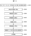
- FIG. 8 is a flowchart showing a printing control method.
- the printing contents and printing conditions such as the type, size and width of characters to be printed are set (S1).
- the maximum printing speed is calculated from (Equation 1), (Equation 2), and (Equation 3) from preset values (S2).
- the moving speeds V117a and V117b when the printed materials 117a and 117b move when passing through the printed material sensor 116 are calculated from the length of the printed material and the light shielding time of the printed material detection sensor 116 (S3, S4).
- the adjustment ink particles are inserted after a predetermined vertical column of ink particles, and when there are ink particles that are charged in front of the adjustment ink particles, the ink particles according to the charge amount of the front charged particles Then, the adjustment ink particles are charged with a certain amount of charge at a low level (S7).
- S7 a low level
- the charge amount is offset, Since the adjustment ink particles are in an almost uncharged state, they are not deflected by the deflection electrode, but are reliably collected by the gutter.
- the charged ink particles for printing start printing according to the charging voltage (S8).
- FIG. 7 shows the print control in consideration of the acceleration of the object to be printed, and shows a diagram related to the adjustment ink particles and the charged ink particles to be printed according to the moving speed of the belt conveyor.
- 7A shows the dot pattern of the ink particles for one vertical column of the printed character and the adjustment ink particles for the character width
- FIG. 7B shows the ink particle charging signal of the dot pattern.
- FIG. 7C shows a signal of the printing timing in the column according to the moving speed when the printing material passes through the printing material detection sensor 116
- FIG. A vertical print timing signal is shown in accordance with the moving speed when passing through.
- FIG. 7A shows an example of a dot pattern of ink particles, and this dot pattern is printed in an example in which five vertical lines are printed.
- FIG. 7B shows an ink particle charging signal corresponding to FIG.
- the dot pattern of the character column on the left side of FIG. 7A corresponds to the ink particle charging signal on the left side of FIG. 7B, and the lowermost printing dot has a lower charging voltage and becomes charged as the printing dot goes up. The voltage gets higher.
- the number of ink particles for adjustment is the number obtained by calculation.
- one dot of the adjustment ink particle corresponds to the interval with the next character (in this case, a vertical line).
- a slight charging voltage E is applied to the adjustment ink particles for charging. This is to prevent the adjustment ink particles from being slightly charged by electrostatic coupling and being collected in the gutter when the charged ink particles to be printed are present in the front. That is, the opposite charge of the same voltage is charged with respect to the charging voltage charged under the influence of the front charged ink particles, the charge of the adjustment ink particles is made zero, and collected with a gutter.
- FIG. 7C shows the printing timing of the columns in accordance with the moving speed when the printed material passes through the printed material detection sensor, and does not consider the acceleration when the belt conveyor moves. For this reason, the printing timing does not coincide with the timing of the ink particle charging signal in FIG.
- the printing timing of the vertical column takes into account the acceleration when the belt conveyor moves according to the moving speed when passing through the nozzles in FIG. 7D, the printing timing is charged with the ink particles in FIG. 7B. Match the signal.
- the acceleration during the movement of the belt conveyor is calculated, the number of ink particles for adjustment that determine the character width is calculated from the speed, etc., and the print quality is improved by printing. Can also be improved.
- the adjustment ink particles are slightly charged due to electrostatic coupling and are not collected in the gutter.
- the charge can be canceled to improve the recoverability by the gutter, and the reliability of the printing operation can be improved.
- Example 2 Next, the conveyance of the printed material of the present invention when two printed material detection sensors are provided will be described with reference to FIG.
- the print object sensors 115 and 116 are arranged separated by a certain distance, the print object 117a is placed at the head on the belt conveyor, and the print object 117b is placed at regular intervals.
- the printed material 117c is placed and transported at intervals. Further, it is assumed that the length of the printed material in the conveyance direction is L, and the printed material passes between the printed material detection sensors at time T. Furthermore, the distance from the printing object detection sensor 116 to the printing nozzle 110 is S1.
- print contents such as the type, size, and character width of characters to be printed and printing conditions are set (S10).
- the maximum printing speed is calculated from (Equation 1) to (Equation 3) from preset values (S20).
- the moving speed of the first point (detection sensor 115) and the second point (detection sensor 116) of the printed matter 117a is determined based on the length of the printed matter and the time during which the printed matter 117a shields the detection sensors 115 and 116.
- this adjustment ink particle is inserted after one preset vertical line and there is a charged ink particle in front of the adjustment ink particle, the adjustment ink particle is adjusted according to the charge amount of the front charged particle.
- the ink particles are charged with a certain amount of charge (S70).
- printing is started according to the voltage charged by the printing ink particles (S80).
- Printing control can be performed by adding or subtracting the number of ink particles for adjustment charged with a certain amount of charge in consideration of electrostatic coupling to the uncharged ink particles used in accordance with the speed of the substrate to be printed. As a result, the print quality can be improved and the reliability of the print operation can be improved.
- Example 3 Next, the conveyance of the printed material of the present invention when the printed material is conveyed on a production line equipped with a rotary encoder will be described with reference to FIG.
- the moving distance and the average period a are determined from the predetermined number of rotary encoder pulses input from the rotary encoder 119 and the pitch between the pulses.
- the average period b is calculated. A method of obtaining the speed and acceleration from this average period and obtaining the necessary number of adjusted ink particles will be described later.
- FIG. 2 shows the configuration of an ink jet recording apparatus when the rotary encoder 119 of Example 3 is provided. 2, parts having the same configuration as in FIG. 1 are given the same numbers, and different parts will be described.
- 115 is a sensor for detecting a printing object
- 117 is a printing object to be printed
- 118 is a belt conveyor for conveying the printing object 117
- 119 is a rotary encoder installed on the belt conveyor 118, which moves the belt conveyor. Convert to number of pulses.
- Reference numeral 120 denotes a pulse signal input circuit of the rotary encoder 119
- 121 denotes a frequency divider that divides the pulse signal of the rotary encoder.
- the setting of printing conditions to match the printing contents to be printed and the conveyance speed, the number of output pulses when the rotary encoder makes one rotation, and the diameter of the rotary encoder pulley are set in advance on the panel 104 and stored in the RAM 102 (S100).
- the pitch between encoder pulses can be calculated from the number of output pulses and the diameter of the encoder pulley. From the print size, ink particle usage rate, and character width, the number of dots in one vertical column used for printing can be calculated by (Equation 12).
- Total number of ink particles for one vertical line (number of vertical dots + character width) x particle usage rate (Equation 12)
- the printing time T per vertical column can be calculated by (Equation 13).
- Printing time for one vertical column T Total number of ink particles for one vertical column / Excitation frequency (Equation 13)
- the highest printing speed V can be calculated in (Equation 14) (S200).
- Maximum printing speed V dot pitch / vertical printing time (14)
- Movement speed Va movement distance / average period a ⁇ number of pulses (Equation 15)
- Movement speed Vb movement distance / average period b ⁇ number of pulses (Equation 16)
- the acceleration a (S500) of the printing material 117 can be calculated from the speed difference and the measurement time of the rotary encoder 119 in (Equation 17). Become.
- Acceleration a (Vb ⁇ Va) / (average period a + average period b) ⁇ number of pulses (Equation 17) From the acceleration a of the printing object 117, the speed Vb of the measured period b, and the time t reaching the nozzle 110, the speed V ′ when the printing object 117 passes through the printing nozzle 110 can be calculated from (Equation 18). (S600).
- V ′ Vb + at (Equation 18)
- the necessary number of ink particles for adjustment can be calculated by (Equation 19) according to the moving speed V ′ of the printing material 117 when passing through the nozzle 110. That means The number of ink particles for adjustment calculated in (Equation 19) is determined.
- the ink particles for adjustment are inserted after a predetermined vertical row of ink particles and the ink particles are charged in front of the ink particles for adjustment, the ink particles for adjustment are adjusted according to the electric charge of the front charged particles.
- a charging voltage is generated for the ink particles with a certain amount of charge (S700).
- the adjustment ink particles start printing according to the created charging voltage (S800).
- the rotary encoder can be used to calculate the acceleration of the printing material and the moving speed of the printing material when passing through the nozzle body, and the printing material when the printing material passes through the nozzle body.
- Printing control can be performed by adjusting the number of adjustment ink particles charged with a certain amount of charge in consideration of electrostatic coupling with uncharged particles used in accordance with the speed of the object. As a result, the print quality can be improved and the reliability of the print operation can be improved.
- MPU microprocessing unit
- RAM random access memory
- ROM read only memory
- 104 .. panel 105 .. print control circuit
- 106 .. printed matter detection circuit 107.
Landscapes
- Ink Jet (AREA)
- Particle Formation And Scattering Control In Inkjet Printers (AREA)
- Electrostatic Spraying Apparatus (AREA)
- Coating Apparatus (AREA)
Abstract
被印字物の移動速度が加減速している場合においても、被印字物の速度に応じて使用する無荷電粒子に静電結合を加味した一定量の電荷を帯電している調整用のインク粒子数を加減し印字制御するインクジェット記録装置を提供する。本発明は、インクジェット記録装置であって、被印字物に印字をするためのインクを収容するインク容器と、該インク容器に接続され、インクを吐出するノズルと、該ノズルから吐出された所定のインクを帯電する帯電電極と、該帯電電極で帯電されたインクを偏向する偏向電極と、印字に使用されないインクを回収するガターと、印字を制御する制御部と、を備え、前記制御部において、印字に使用されるインク粒子に隣接する印字に使用されないインク粒子を前記帯電電極で帯電するよう制御することを特徴とする。
Description
本発明は、ノズルより粒子化されたインクを連続的に噴出するインクジェット記録装置及びその印字制御方法に関する。
本発明の先行技術文献として、特許文献1(WO08/102458号公報)がある。この文献には、「帯電波形に対して、インク滴の状態を黒丸と三角形で表し、黒丸は印字に使用する荷電インク滴を、三角形は印字に使用しない無荷電インク滴をそれぞれ表す。無荷電インク滴は、印字するマトリクス文字の空白領域になるときと、縦ドット列間の時間を調整する役割を有し、どちらにおいても、生成されるインク滴がヘッドから飛び出さずにガター15で回収されるように電荷が印加されないものである。第14図と第15図に示した低速印字状態は、ノズル11から噴出するインクのインク滴が被印字物19に所定個数並ぶ時間に対して、被印字物が移動する速度が相対的に遅い状態である。そのため先の縦ドット列の印字終了から後の縦ドット列の印字開始までの時間を調整する必要がある。Y個のインク滴が印字された点の列である縦Yドットで4列のマトリクス文字の各縦ドット列に、α個分の印字しない無荷電インク滴を使用した分として加算する。第15図においては、縦5ドットで横に4列のマトリクス文字に対して、実際に印字に使用する5個のインク滴に、印字されない7個の無荷電インク滴を加えて、縦ドット列として取り扱っている。」と記載されている。
上記したように、特許文献1では、IJPの印字において荷電インク粒子の間に調整用の無荷電インク粒子を挿入して印字している。このとき、ノズルから噴出するマイナスの電荷を持つインク粒子が偏向電極の中を通過するとき、静電気による引力により偏向電極のプラス側に偏向され印字物に印字する。しかし、調整用の無荷電インク粒子は、この調整用の無荷電インク粒子に隣接するマイナスに帯電された荷電インク粒子と静電結合することによって、調整用の無荷電インク粒子がプラスに帯電することがある。これにより、調整用のインク粒子が偏向電極を通過する際に偏向電極“-”側方向に偏向され、ガターに戻らないという課題がある。
また、特許文献1では、無荷電粒子を荷電粒子間に挿入する方法(以下、粒子使用率という)で、縦1列分のインク粒子総数を決定している。このとき搬送速度が一定であり、無荷電粒子を含めた印字に使用するインク粒子の使用個数が一定数である以上、理論的にはIJPの印字結果として縦列間の距離は常に同じとなる。しかし被印字物の搬送速度が変動した場合には、おのずとIJPの印字した縦列間の距離が変わってくる。
特許文献1では、被印字物の移動速度が一定速度のときのみを考慮し、被印字物検知センサとノズルの間に被印字物の移動速度が加減速する点を考慮していないから、印字の縦列間の距離にばらつきが生じる可能性がある。
本発明は、上記課題を解決し、印字品質を向上するとともに印字動作の信頼性を向上することを目的とする。
上記課題を解決するために、例えば特許請求の範囲に記載の構成を採用する。本願は上記課題を解決する手段を複数含んでいるが、その一例を挙げるならば、被印字物に印字をするためのインクを収容するインク容器と、該インク容器に接続され、インクを吐出するノズルと、該ノズルから吐出された所定のインクを帯電する帯電電極と、該帯電電極で帯電されたインクを偏向する偏向電極と、印字に使用されないインクを回収するガターと、印字を制御する制御部と、を備えたインクジェット記録装置であって、前記制御部において、印字に使用されるインク粒子に隣接する印字に使用されないインク粒子を前記帯電電極で帯電するよう制御することを特徴とする。
本発明によれば、印字品質を向上するとともに、印字動作の信頼性を向上することが可能なインクジェット記録装置を提供することができる。
以下、本発明の実施の形態を図面を用いて説明する。
(実施例1)
図1に本発明の実施例1に関わるインクジェット記録装置の構成を示す。図1において、101はインクジェット記録装置全体を制御するMPU(マイクロプロセッシングユニット)、102はインクジェット記録装置内で一時的にデータを記憶しておくRAM(ランダムアクセスメモリー)、103はベルトコンベア速度と印字速度を計算するソフトウェアおよびデータを記憶するROM(リードオンリーメモリ)、104は被印字物の長さ、印字距離、書き出し位置、及び印字文字列の幅を入力するパネル、105はインクジェット記録装置の印字動作を制御する印字制御回路、106は被印字物検出回路、107は被印字物の検知時間と入力された被印字物の長さからベルトコンベア速度を計算する移動速度計測回路、108は印字内容を文字信号にする文字信号発生回路、109はデータ等を送るバス、110はインクを噴出するノズル、111はノズルより噴出したインクが粒子になりそのインク粒子に電荷を加える帯電電極、112は帯電したインク粒子を偏向する偏向電極、113は印字に使用しないインクを回収するガター、114はガターより回収されたインクを再びノズルへ供給するポンプ、115、116は被印字物を検出するセンサ、117は印字の対象となる被印字物、118は被印字物を搬送するベルトコンベアである。
(実施例1)
図1に本発明の実施例1に関わるインクジェット記録装置の構成を示す。図1において、101はインクジェット記録装置全体を制御するMPU(マイクロプロセッシングユニット)、102はインクジェット記録装置内で一時的にデータを記憶しておくRAM(ランダムアクセスメモリー)、103はベルトコンベア速度と印字速度を計算するソフトウェアおよびデータを記憶するROM(リードオンリーメモリ)、104は被印字物の長さ、印字距離、書き出し位置、及び印字文字列の幅を入力するパネル、105はインクジェット記録装置の印字動作を制御する印字制御回路、106は被印字物検出回路、107は被印字物の検知時間と入力された被印字物の長さからベルトコンベア速度を計算する移動速度計測回路、108は印字内容を文字信号にする文字信号発生回路、109はデータ等を送るバス、110はインクを噴出するノズル、111はノズルより噴出したインクが粒子になりそのインク粒子に電荷を加える帯電電極、112は帯電したインク粒子を偏向する偏向電極、113は印字に使用しないインクを回収するガター、114はガターより回収されたインクを再びノズルへ供給するポンプ、115、116は被印字物を検出するセンサ、117は印字の対象となる被印字物、118は被印字物を搬送するベルトコンベアである。
次に、印字内容入力から印字を完了するまでの一連の動作について説明する。印字内容は、印字内容データをパネル104によって入力してRAM102に保存することで設定することができる。また、パネル104より入力し設定された文字サイズ、文字幅、インク粒子の使用率の設定から(数1)で縦1列分のインク粒子総数は計算可能となる。
縦1列分のインク粒子総数=(文字縦ドット数+文字幅)×粒子使用率 (数1)
その縦1列分のインク粒子総数と生成されるインク粒子数の周期から(数2)で縦1列あたりの印字時間Tは計算可能となる。
縦1列の印字時間T=縦1列分のインク粒子総数/励振周波数 (数2)
縦1列の印字時間と縦列間の距離(以下、ドットピッチという)に基づいて(数3)で該当設定に対応する最高印字速度Vが計算可能となる。
最高印字速度V=ドットピッチ/縦1列の印字時間 (数3)
次に、図3、図6~図8を用いて、従来の技術と本発明についての違いについて説明する。図3は被印字物検出センサを1つ用いた時の被印字物搬送の図で、図6は従来技術における搬送速度に応じて調整用インク粒子とインク粒子帯電の関係図である。図7は本発明で搬送速度に応じて調整用インク粒子とインク粒子帯電の関係図で、図8は本発明の制御処理フローチャートである。
その縦1列分のインク粒子総数と生成されるインク粒子数の周期から(数2)で縦1列あたりの印字時間Tは計算可能となる。
縦1列の印字時間T=縦1列分のインク粒子総数/励振周波数 (数2)
縦1列の印字時間と縦列間の距離(以下、ドットピッチという)に基づいて(数3)で該当設定に対応する最高印字速度Vが計算可能となる。
最高印字速度V=ドットピッチ/縦1列の印字時間 (数3)
次に、図3、図6~図8を用いて、従来の技術と本発明についての違いについて説明する。図3は被印字物検出センサを1つ用いた時の被印字物搬送の図で、図6は従来技術における搬送速度に応じて調整用インク粒子とインク粒子帯電の関係図である。図7は本発明で搬送速度に応じて調整用インク粒子とインク粒子帯電の関係図で、図8は本発明の制御処理フローチャートである。
図3は、実施例1の被印字物検出センサを1個設置したときの被印字物を搬送する図を示す。図3において、ベルトコンベア上に被印字物117aが先頭に載置され、一定の間隔において被印字物117b、117cが載置され、搬送される。そして、被印字物の搬送方向の長さをL、被印字物検出センサ116から印字ノズル110までの距離をS1とする。本発明は、被印字物検出センサ116から印字ノズル110が動作するまでの間に縦1列のインク粒子の数、印字時間、速度および加速度を演算し、調整用のインク粒子数を設定し、印字するものである。
ここで、先ず従来の技術について、図6を用いて説明する。図6は、被印字物の移動速度に応じて印字する文字幅の調整用インク粒子と、文字印字のための帯電インク粒子の関係を示している。図6において、図6(a)は印字文字の縦1列分のインク粒子及び文字幅のための調整用インク粒子のドットパターンを示し、図6(b)はドットパターンのインク粒子帯電信号を示し、図6(c)は被印字物が被印字物検知センサ116を通過する時の移動速度に応じた縦列の印字タイミングの信号を示し、図6(d)は被印字物が印字ノズル110を通過する時の移動速度に応じて縦列の印字タイミングの信号を示している。
図6(a)及び図6(b)において、図6(a)の左側の縦1列分のインク粒子(黒丸5個)及び調整用インク粒子(白丸2個)は、図6(b)に示した帯電信号(縦軸は帯電電圧を示す)をみると、印字ドットの下側の帯電電圧は低く、次第に高くなっていき、調整用インク粒子2ドットが次の縦1列分の印字との幅を決める。図6(a)及び(b)は、縦線を5本印字するドットパターンを示す。図6(c)に示した印字タイミングは、コンベアの移動時に生じる加速度を考慮せず、一定時間t1で印字する。従って、印字タイミングは(b)のインク粒子帯電信号の立ち上がり時間と一致する。しかし、コンベアの移動時の加速度を考慮した図6(d)の印字ノズル通過時の移動速度に応じて縦列の印字タイミングの周期t‘は、図6(b)のインク粒子帯電信号の周期とは一致しないでずれる。
従って、印字したとき、印字文字幅に僅かむらが生じ、印字品質が僅か劣る。また、図6に示すように、センサを通過する移動速度に応じて挿入する調整用の無帯電インク粒子数を設定するが、被印字物検出センサ116を通過するタイミングからノズル本体110を通過するまでの間に被印字物117aが加速して移動する場合でも、その調整用インク粒子数は従来変更できなかった。また、調整用のインク粒子が無荷電であるため、挿入された調整用インク粒子の前方に、帯電されたインク粒子が存在する場合は、静電結合によって調整用の無荷電インク粒子から電荷が奪われるため、調整用のインク粒子が偏向電極と通過する際にインク粒子が偏向電極“-”側方向に偏向され、ガターに戻らず周囲に付着している。
次に、従来技術の課題である加速度を考慮した印字の制御方法について説明する。図8は、印字の制御方法を表すフローチャートである。図8において、先ず、印字する文字の種類、大きさ、文字幅などの印字内容及び印字条件を設定する(S1)。次に、予め設定された値より(数1)(数2)及び(数3)より最高印字速度を算出する(S2)。そして、被印字物の長さと被印字物検出センサ116の遮光時間から被印字物117a、117bが被印字物センサ116を通過するときの移動する時の移動速度V117aとV117bを算出する(S3、S4)。この第1被印字物117a及び第2被印字物117bの移動速度と、2個の被印字物を検出するタイミングの差t1に基づいて、(数4)で被印字物117bの加速度aを算出する(S5)。
加速度a=(V117a-V117b)/t1 ‥‥(数4)
次に、演算された被印字物117bの加速度aと、被印字物センサ116を通過する時の移動速度V117bおよびそのセンサとノズル本体110の距離S1に(数5)及び(数6)が成立し、被印字物117bが印字ノズル本体110を通過するときの速度V‘が演算可能となる(S6)。
S1=V117b×t+0.5×at2 ‥‥(数5)
V‘=V117b+at ‥‥(数6)
そして、そのノズル本体110を通過するときの被印字物117bの移動速度V‘に応じて挿入する、必要な調整用インク粒子が(数7)で演算して求まる。
 調整用インク粒子数は、上記(数7)により演算され求まる。
加速度a=(V117a-V117b)/t1 ‥‥(数4)
次に、演算された被印字物117bの加速度aと、被印字物センサ116を通過する時の移動速度V117bおよびそのセンサとノズル本体110の距離S1に(数5)及び(数6)が成立し、被印字物117bが印字ノズル本体110を通過するときの速度V‘が演算可能となる(S6)。
S1=V117b×t+0.5×at2 ‥‥(数5)
V‘=V117b+at ‥‥(数6)
そして、そのノズル本体110を通過するときの被印字物117bの移動速度V‘に応じて挿入する、必要な調整用インク粒子が(数7)で演算して求まる。
また、調整用のインク粒子は、予め設定された縦1列分のインク粒子の後に挿入し、調整用インク粒子の前方に帯電するインク粒子が存在する場合、前方の帯電粒子の電荷量に応じて調整用インク粒子を低いレベルの一定量の電荷で帯電させる(S7)。調整用インク粒子に低いレベルで帯電させることにより、調整用インク粒子の前方に位置する印字に使用する帯電されたインク粒子と静電結合が生じても、電荷量が相殺されることになり、調整用インク粒子が略無帯電状態となるため、偏向電極によって偏向されず、確実にガターで回収されるようになる。次に、印字用の帯電したインク粒子が帯電電圧に従って印字を開始する(S8)。
次に、上記の印字の制御方法による被印字物への印字について、図7を用いて説明する。図7は、被印字物の加速度を考慮した印字制御を示すものであり、ベルトコンベアの移動速度に応じて調整用インク粒子と印字する帯電したインク粒子に関係する図を示している。図7において、図7(a)は印字文字の縦1列分のインク粒子及び文字幅のための調整用インク粒子のドットパターンを示し、図7(b)はドットパターンのインク粒子帯電信号を示す。また、図7(c)は被印字物が被印字物検知センサ116を通過するときの移動速度に応じた縦列の印字タイミングの信号を示し、図7(d)は被印字物が印字ノズル110を通過するときの移動速度に応じて縦列の印字タイミングの信号を示している。図7(a)は、インク粒子のドットパターンの例を示し、このドットパターンの印字は垂直な線を5本印字する例である。図7(a)に対応するインク粒子帯電信号を図7(b)に示す。
図7(a)の左側の文字縦列のドットパターンは、図7(b)の左側のインク粒子帯電信号に対応し、最も下の印字ドットが帯電電圧が低く、印字ドットが上にいくに従って帯電電圧は高くなっていく。そして、5ドット目の印字が終了すると、調整用インク粒子が1ドットあり、この調整用インク粒子数は、演算により求めた個数である。また、この調整用インク粒子の1ドットは、次の文字(ここでは縦線となる)との間隔に対応する。さらに、調整用インク粒子に僅かに帯電電圧Eを印加し、帯電させている。これは、印字する帯電インク粒子が前方に存在する場合、調整用インク粒子が静電結合により僅か帯電してガターに回収されないことを防止するためである。すなわち、前方の帯電インク粒子の影響で帯電した帯電電圧に対して同量電圧の反対電荷を帯電させ、調整用インク粒子の電荷をゼロにし、ガターで回収するようにする。
次に、図7(c)は、被印字物検知センサを被印字物が通過したときの移動速度に応じて縦列の印字タイミングを表しており、ベルトコンベアの移動時の加速度を考慮していないため、印字タイミングは図7(b)のインク粒子帯電信号のタイミングとは一致していない。次に、図7(d)のノズル通過時の移動速度に応じて縦列の印字タイミングは、ベルトコンベアの移動時の加速度を考慮しているため、印字タイミングは図7(b)のインク粒子帯電信号と一致する。上記のように、本発明によれば、ベルトコンベアの移動時の加速度を演算し、速度等より文字幅を決定する調整用インク粒子数を演算して求め、印字することで印字品質を従来よりも向上させることができる。また、印字する帯電インク粒子が前方に存在し、その後に調整用インク粒子が存在する場合、静電結合により調整用インク粒子が僅か帯電し、ガターに回収されなかったが、調整用インク粒子に強制的に帯電させることにより電荷を相殺してガターによる回収性を向上し、印字動作の信頼性を向上することができる。
(実施例2)
次に、被印字物検出センサを2個設けた場合の本発明の被印字物搬送について、図4を用いて説明する。図4において、被印字物センサ115及び116を一定の間隔離して配置し、ベルトコンベア上に被印字物117aが先頭に載置され、一定間隔おいて被印字物117bが載置され、さらに一定間隔おいて被印字物117cが載置され、搬送される状態を示している。また、被印字物の搬送方向の長さをLとし、被印字物検出センサ間は被印字物が時間Tで通過するとする。さらに、被印字物検出センサ116から印字ノズル110までの距離をS1とする。
次に、被印字物検出センサを2個設けた場合の本発明の被印字物搬送について、図4を用いて説明する。図4において、被印字物センサ115及び116を一定の間隔離して配置し、ベルトコンベア上に被印字物117aが先頭に載置され、一定間隔おいて被印字物117bが載置され、さらに一定間隔おいて被印字物117cが載置され、搬送される状態を示している。また、被印字物の搬送方向の長さをLとし、被印字物検出センサ間は被印字物が時間Tで通過するとする。さらに、被印字物検出センサ116から印字ノズル110までの距離をS1とする。
実施例2において、印字の制御方法を図9のフローチャートを用いて説明する。先ず、印字する文字の種類、大きさ、文字幅などの印字内容及び印字条件を設定する(S10)。次に、予め設定された値より(数1)~(数3)より最高印字速度を算出する(S20)。そして、被印字物の長さと、被印字物117aが検出センサ115と116を遮光する時間とより被印字物117aの第1地点(検出センサ115)及び第2地点(検出センサ116)の移動速度V115aとV116aを算出し(S30、S40)、2個の検出センサ間の距離を通過時間t1に基づいて、(数8)で被印字物117aの加速度aを求める(S50)。
加速度a=(V116a-V115a)/t1 (数8)
計算された被印字物117aの加速度aと被印字物検出センサ116を通過するときの移動速度V116a及びその検出センサ116と印字ノズル110の距離S1による(数9)と(数10)で被印字物117aが印字ノズル110を通過するときの速度V‘が計算できる。
S1=V116a×t+0.5at2 (数9)
V‘=V116a+at (数10)
加速度a=(V116a-V115a)/t1 (数8)
計算された被印字物117aの加速度aと被印字物検出センサ116を通過するときの移動速度V116a及びその検出センサ116と印字ノズル110の距離S1による(数9)と(数10)で被印字物117aが印字ノズル110を通過するときの速度V‘が計算できる。
S1=V116a×t+0.5at2 (数9)
V‘=V116a+at (数10)
そして、ノズル110を通過するときの被印字物117aの移動速度V‘に応じて挿入する必要な調整用インク粒子数が(数11)より計算可能となる。
 上記の(数11)において計算された調整用インク粒子数を決定する。
また、この調整用インク粒子が予め設定された縦1列分の後に挿入し、調整用インク粒子の前方に帯電したインク粒子が存在する場合に、前方の帯電粒子の電荷量に応じて調整用インク粒子を一定量の電荷で帯電させる(S70)。そして、印字用インク粒子が帯電した電圧に従って、印字を開始する(S80)。
以上述べた構成にすることで、被印字物検出センサを2個使用し、被印字物の加速度及びノズル本体を通過するときの被印字物の移動速度を計算でき、被印字物がノズルを通過するときの被印字物の速度に応じて使用する無荷電インク粒子に静電結合を加味した一定量の電荷を帯電している調整用インク粒子数を加減して印字制御することができる。これにより、印字品質を向上するとともに、印字動作の信頼性を向上することができる。
(実施例3)
次に、被印字物がロータリーエンコーダを備える生産ラインで搬送されるときの本発明の被印字物の搬送について、図5を用いて説明する。図5において、被印字物117を被印字物検出センサ115で検出した後、ロータリーエンコーダ119から入力される予め決められたロータリーエンコーダパルス数およびパルス間のピッチから、その移動距離および平均周期aと平均周期bを計算する。この平均周期より速度、加速度を求め、必要な調整インク粒子数を求める方法については後述する。
次に、被印字物がロータリーエンコーダを備える生産ラインで搬送されるときの本発明の被印字物の搬送について、図5を用いて説明する。図5において、被印字物117を被印字物検出センサ115で検出した後、ロータリーエンコーダ119から入力される予め決められたロータリーエンコーダパルス数およびパルス間のピッチから、その移動距離および平均周期aと平均周期bを計算する。この平均周期より速度、加速度を求め、必要な調整インク粒子数を求める方法については後述する。
実施例3のロータリーエンコーダ119を設けた場合のインクジェット記録装置構成を図2に示す。図2において、図1と構成が同じ個所は同じ番号を付し、異なる箇所について説明する。115は被印字物を検出するセンサ、117は印字の対象となる被印字物、118は被印字物117を搬送するベルトコンベア、119はベルトコンベア118に設置したロータリーエンコーダで、ベルトコンベアの移動をパルス数に変換する。120はロータリーエンコーダ119のパルス信号の入力回路で、121はロータリーエンコーダのパスル信号を分周する分周器を示す。
次に、図10のフローチャートを用いて実施例3の発明の制御方法について説明する。先ず、印字したい印字内容と搬送速度に合わせる印字条件の設定およびロータリーエンコーダが1回転したときの出力パルス数およびロータリーエンコーダプーリの直径を予めパネル104にて設定し、RAM102に保存する(S100)。このとき、エンコーダパルス間のピッチを出力パルス数およびエンコーダプーリの直径から計算可能となる。印字サイズ、インク粒子の使用率、文字幅から印字に使用する縦1列のドット数は(数12)で計算可能となる。
縦1列分のインク粒子総数=(文字縦ドット数+文字幅)×粒子使用率 (数12)
その縦1列のインク粒子数と生成されるインク粒子数の周期から縦1列あたりの印字時間Tは(数13)で計算可能となる。
縦1列の印字時間T=縦1列分のインク粒子総数/励振周波数 (数13)
縦1列の印字時間とドットピッチに基づいて(数14)で最高の印字速度Vが計算可能
となる(S200)。
最高印字速度V=ドットピッチ/縦1列の印字時間 (数14)
被印字物がロータリーエンコーダを備える生産ラインで搬送されるときに(図5)、被印字物を被印字物検出センサで検出後、ロータリーエンコーダ119から入力されるあらかじめ決められたロータリーエンコーダパルス数およびパルス間のピッチから、その移動距離および平均周期aと平均周期bを計算する。その計算した平均周期から(数15)の移動速度Va(S300)と(数16)の移動速度Vb(S400)が計算可能となる。
移動速度Va=移動距離/平均周期a×パルス数 (数15)
移動速度Vb=移動距離/平均周期b×パルス数 (数16)
被印字物117の移動速度VaとVbから計測された速度差に基づいて、(数17)でその速度差とロータリーエンコーダ119の計測時間から被印字物117の加速度a(S500)が計算可能となる。
加速度a=(Vb-Va)/(平均周期a+平均周期b)×パルス数 (数17)
被印字物117の加速度aと前記計測された周期bの速度Vbおよびノズル110に到達する時間tから(数18)で被印字物117が印字ノズル110を通過する時の速度V′が計算可能となる(S600)。
縦1列分のインク粒子総数=(文字縦ドット数+文字幅)×粒子使用率 (数12)
その縦1列のインク粒子数と生成されるインク粒子数の周期から縦1列あたりの印字時間Tは(数13)で計算可能となる。
縦1列の印字時間T=縦1列分のインク粒子総数/励振周波数 (数13)
縦1列の印字時間とドットピッチに基づいて(数14)で最高の印字速度Vが計算可能
となる(S200)。
最高印字速度V=ドットピッチ/縦1列の印字時間 (数14)
被印字物がロータリーエンコーダを備える生産ラインで搬送されるときに(図5)、被印字物を被印字物検出センサで検出後、ロータリーエンコーダ119から入力されるあらかじめ決められたロータリーエンコーダパルス数およびパルス間のピッチから、その移動距離および平均周期aと平均周期bを計算する。その計算した平均周期から(数15)の移動速度Va(S300)と(数16)の移動速度Vb(S400)が計算可能となる。
移動速度Va=移動距離/平均周期a×パルス数 (数15)
移動速度Vb=移動距離/平均周期b×パルス数 (数16)
被印字物117の移動速度VaとVbから計測された速度差に基づいて、(数17)でその速度差とロータリーエンコーダ119の計測時間から被印字物117の加速度a(S500)が計算可能となる。
加速度a=(Vb-Va)/(平均周期a+平均周期b)×パルス数 (数17)
被印字物117の加速度aと前記計測された周期bの速度Vbおよびノズル110に到達する時間tから(数18)で被印字物117が印字ノズル110を通過する時の速度V′が計算可能となる(S600)。
V′=Vb+at (数18)
そのノズル110を通過する時の被印字物117の移動速度V′に応じて必要な調整用のインク粒子数が(数19)で計算可能となる。
つまり、
 (数19)で計算された調整用のインク粒子数を決定する。また、その調整用のインク粒子があらかじめ設定された縦1列分のインク粒子の後に挿入し、調整用のインク粒子の前方にインク粒子が帯電する場合において前方帯電粒子の電量に応じて調整用インク粒子を一定量の電荷で帯電電圧を作成する(S700)。調整用のインク粒子がその作成された帯電電圧に従って印字を開始する(S800)。
そのノズル110を通過する時の被印字物117の移動速度V′に応じて必要な調整用のインク粒子数が(数19)で計算可能となる。
つまり、
上記した構成とすることで、ロータリーエンコーダを利用し、被印字物の加速度およびノズル本体を通過する際に被印字物の移動速度を計算でき、被印字物がノズル本体を通過する際の被印字物の速度に応じて使用する無荷電粒子に静電結合を加味した一定量の電荷を帯電している調整用のインク粒子数を加減して印字制御することができる。これにより、印字品質を向上するとともに、印字動作の信頼性を向上することができる。
101‥MPU(マイクロプロセッシングユニット)、102‥RAM(ランダムアクセスメモリー)、103‥ROM(リードオンリーメモリ)、104‥パネル、105‥印字制御回路、106‥被印字物検出回路、107‥移動速度計測回路、108‥文字信号発生回路、109‥バス、110‥ノズル、111‥帯電電極、112‥偏向電極、113‥ガター、114‥ポンプ、115、116‥被印字物検出センサ、117‥被印字物、118‥ベルトコンベア、119‥ロータリーエンコーダ、120‥ロータリーエンコーダのパルス信号入力回路、121‥ロータリーエンコーダのパルス信号の分周器。
Claims (8)
- 被印字物に印字をするためのインクを収容するインク容器と、
該インク容器に接続され、インクを吐出するノズルと、
該ノズルから吐出された所定のインクを帯電する帯電電極と、
該帯電電極で帯電されたインクを偏向する偏向電極と、
印字に使用されないインクを回収するガターと、
印字を制御する制御部と、
を備えたインクジェット記録装置であって、
前記制御部において、
印字に使用されるインク粒子に隣接する印字に使用されないインク粒子を前記帯電電極で帯電するよう制御することを特徴とするインクジェット記録装置。 - 請求項1に記載のインクジェット記録装置であって、
前記制御部において、
被印字物の加速度から前記被印字物が前記ノズルを通過する際の移動速度を算出し、前記移動速度に応じて印字に使用されないインク粒子数を算出し、該算出された印字に使用されないインク粒子数と所定の印字に使用されるインク粒子数とを用いた総インク粒子数で印字を行うよう制御することを特徴とするインクジェット記録装置。 - 請求項2記載のインクジェット記録装置であって、
被印字物の基準位置での通過時間を検出する、複数の検出部と、
前記被印字物の移動速度を算出する移動速度計測回路とを有し、
第1の検出部の検出情報に基づいて、被印字物の第1の地点での第1の移動速度を算出し、
第2の検出部の検出情報に基づいて、被印字物の第2の地点での第2の移動速度を算出し、
前記第1、第2の移動速度と、前記被印字物が第1と第2の地点間の距離を通過する時間とに基づいて前記被印字物の加速度を算出することを特徴とするインクジェット記録装置。 - 請求項2記載のインクジェット記録装置であって、
被印字物の基準位置での通過時間を検出する、検出部と
被印字物の移動速度を算出する移動速度計測回路とを有し、
前記検出部の検出情報に基づいて、前記被印字物の搬送方向前方に位置する他の被印字物の所定地点での移動速度と、前記被印字物の前記所定地点での移動速度とを算出し、
前記被印字物及び前記他の被印字物の前記所定地点での移動速度と、前記他の被印字物と前記被印字物とが前記所定地点に到達した時間の差分時間とに基づいて、前記被印字物の加速度を算出することを特徴とするインクジェット記録装置。 - 請求項2に記載のインクジェット記録装置であって、
被印字物の移動速度を算出する移動速度計測回路を有し、
前記被印字物がノズル本体を通過するときの移動速度を計算し、
前記移動速度に応じて調整用インク粒子数と挿入位置を決定し、
前記挿入する調整用のインク粒子の前方にインク粒子が帯電されている場合、インク粒子が生成される際に前方粒子との静電結合によって、既インク粒子の電荷が損なわれるため一定量の電荷量をあらかじめ帯電させることを特徴とするインクジェット記録装置。 - 請求項3から5のいずれかに記載のインクジェット記録装置であって、
前記検出部は、被印字物を検知し、被印字物の通過時間を検出するセンサであることを特徴とするインクジェット記録装置。 - 請求項3から5のいずれかに記載のインクジェット記録装置であって、
前記検出部は被印字物の移動量によって信号を発生するエンコーダであることを特徴とするインクジェット記録装置。 - 印字対象物に印字をするためのインクを収容するインク容器と、
前記インク容器に接続され、インクを吐出するノズルと、
前記ノズルから吐出された所定のインクを帯電する帯電電極と、
前記帯電電極で帯電されたインクを偏向する偏向電極と、
印字に使用されないインクを回収するガターと、
制御部と、
を備えたインクジェット記録装置の制御方法であって、
印字に使用されるインク粒子に隣接する印字に使用されないインク粒子を前記帯電電極で帯電するよう制御すること
を特徴とするインクジェット記録装置の印字制御方法。
Priority Applications (3)
| Application Number | Priority Date | Filing Date | Title |
|---|---|---|---|
| US14/418,095 US9233532B2 (en) | 2012-07-30 | 2013-05-28 | Inkjet recording device and printing control method of same |
| CN201380040844.2A CN104520108B (zh) | 2012-07-30 | 2013-05-28 | 喷墨记录装置和打印控制方法 |
| EP13825233.3A EP2881258B1 (en) | 2012-07-30 | 2013-05-28 | Inkjet recording device and print control method |
Applications Claiming Priority (2)
| Application Number | Priority Date | Filing Date | Title |
|---|---|---|---|
| JP2012168093A JP6058938B2 (ja) | 2012-07-30 | 2012-07-30 | インクジェット記録装置及び印字制御方法 |
| JP2012-168093 | 2012-07-30 |
Publications (1)
| Publication Number | Publication Date |
|---|---|
| WO2014020979A1 true WO2014020979A1 (ja) | 2014-02-06 |
Family
ID=50027670
Family Applications (1)
| Application Number | Title | Priority Date | Filing Date |
|---|---|---|---|
| PCT/JP2013/064813 Ceased WO2014020979A1 (ja) | 2012-07-30 | 2013-05-28 | インクジェット記録装置及び印字制御方法 |
Country Status (5)
| Country | Link |
|---|---|
| US (1) | US9233532B2 (ja) |
| EP (1) | EP2881258B1 (ja) |
| JP (1) | JP6058938B2 (ja) |
| CN (1) | CN104520108B (ja) |
| WO (1) | WO2014020979A1 (ja) |
Cited By (1)
| Publication number | Priority date | Publication date | Assignee | Title |
|---|---|---|---|---|
| EP3281793A4 (en) * | 2015-04-10 | 2018-11-14 | Hitachi Industrial Equipment Systems Co., Ltd. | Ink jet recording apparatus |
Families Citing this family (7)
| Publication number | Priority date | Publication date | Assignee | Title |
|---|---|---|---|---|
| CN104924761B (zh) * | 2015-06-09 | 2016-06-29 | 厦门英杰华机电科技有限公司 | Cij喷码机打印速度控制方法 |
| CN107009740A (zh) * | 2017-03-30 | 2017-08-04 | 厦门英杰华机电科技有限公司 | Cij喷码机变速打印控制算法 |
| JP6349480B1 (ja) | 2017-05-25 | 2018-06-27 | 武蔵エンジニアリング株式会社 | 液体材料塗布装置および液体材料塗布方法 |
| JP6919988B2 (ja) * | 2017-08-31 | 2021-08-18 | 株式会社日立産機システム | インクジェット記録装置およびその制御方法 |
| JP6471258B2 (ja) * | 2018-06-04 | 2019-02-13 | 武蔵エンジニアリング株式会社 | 液体材料塗布装置および液体材料塗布方法 |
| GB2575077A (en) | 2018-06-28 | 2020-01-01 | Domino Uk Ltd | Stroke direction offset adjustment |
| JP7429180B2 (ja) * | 2020-10-15 | 2024-02-07 | 株式会社日立産機システム | インクジェット記録装置およびインクジェット記録装置の制御方法 |
Citations (4)
| Publication number | Priority date | Publication date | Assignee | Title |
|---|---|---|---|---|
| JPS57115357A (en) * | 1981-01-07 | 1982-07-17 | Ricoh Co Ltd | Compensating method for deflective strain of charged ink particle |
| JP2000233504A (ja) * | 1999-02-15 | 2000-08-29 | Keyence Corp | 荷電制御型インクジェットプリンタ |
| JP2000289208A (ja) * | 1999-04-06 | 2000-10-17 | Toray Ind Inc | インクジェット記録装置および記録方法 |
| WO2008102458A1 (ja) | 2007-02-23 | 2008-08-28 | Hitachi Industrial Equipment Systems Co., Ltd. | インクジェット記録装置 |
Family Cites Families (10)
| Publication number | Priority date | Publication date | Assignee | Title |
|---|---|---|---|---|
| US3786517A (en) * | 1972-09-05 | 1974-01-15 | Ibm | Ink jet printer with ink system filter means |
| US4658269A (en) * | 1986-06-02 | 1987-04-14 | Xerox Corporation | Ink jet printer with integral electrohydrodynamic electrodes and nozzle plate |
| JP3218421B2 (ja) * | 1994-10-27 | 2001-10-15 | 株式会社日立製作所 | 荷電偏向型液体噴射記録方法および装置 |
| US6746108B1 (en) * | 2002-11-18 | 2004-06-08 | Eastman Kodak Company | Method and apparatus for printing ink droplets that strike print media substantially perpendicularly |
| JP2004171212A (ja) * | 2002-11-19 | 2004-06-17 | Hitachi Ltd | サービス実行方法及びサービス提供システム |
| US7502793B2 (en) | 2004-02-10 | 2009-03-10 | International Business Machines Corporation | Method and apparatus for assigning roles to devices using physical tokens |
| EP2058131A1 (en) * | 2007-11-09 | 2009-05-13 | Nederlandse Organisatie voor toegepast- natuurwetenschappelijk onderzoek TNO | Droplet selection mechanism |
| JP5202203B2 (ja) * | 2008-09-17 | 2013-06-05 | 株式会社日立産機システム | インクジェット記録装置 |
| EP2465681B1 (en) * | 2009-08-11 | 2014-11-05 | Hitachi Industrial Equipment Systems Co., Ltd. | Inkjet recording device and printing head |
| JP5779534B2 (ja) * | 2012-03-30 | 2015-09-16 | 株式会社日立産機システム | インクジェット記録装置及び印字制御方法 |
-
2012
- 2012-07-30 JP JP2012168093A patent/JP6058938B2/ja active Active
-
2013
- 2013-05-28 US US14/418,095 patent/US9233532B2/en active Active
- 2013-05-28 CN CN201380040844.2A patent/CN104520108B/zh active Active
- 2013-05-28 WO PCT/JP2013/064813 patent/WO2014020979A1/ja not_active Ceased
- 2013-05-28 EP EP13825233.3A patent/EP2881258B1/en active Active
Patent Citations (4)
| Publication number | Priority date | Publication date | Assignee | Title |
|---|---|---|---|---|
| JPS57115357A (en) * | 1981-01-07 | 1982-07-17 | Ricoh Co Ltd | Compensating method for deflective strain of charged ink particle |
| JP2000233504A (ja) * | 1999-02-15 | 2000-08-29 | Keyence Corp | 荷電制御型インクジェットプリンタ |
| JP2000289208A (ja) * | 1999-04-06 | 2000-10-17 | Toray Ind Inc | インクジェット記録装置および記録方法 |
| WO2008102458A1 (ja) | 2007-02-23 | 2008-08-28 | Hitachi Industrial Equipment Systems Co., Ltd. | インクジェット記録装置 |
Non-Patent Citations (1)
| Title |
|---|
| See also references of EP2881258A4 |
Cited By (2)
| Publication number | Priority date | Publication date | Assignee | Title |
|---|---|---|---|---|
| EP3281793A4 (en) * | 2015-04-10 | 2018-11-14 | Hitachi Industrial Equipment Systems Co., Ltd. | Ink jet recording apparatus |
| US10500843B2 (en) | 2015-04-10 | 2019-12-10 | Hitachi Industrial Equipment Systems Co., Ltd. | Ink jet recording apparatus |
Also Published As
| Publication number | Publication date |
|---|---|
| JP6058938B2 (ja) | 2017-01-11 |
| JP2014024294A (ja) | 2014-02-06 |
| EP2881258A4 (en) | 2016-08-10 |
| CN104520108A (zh) | 2015-04-15 |
| US20150165761A1 (en) | 2015-06-18 |
| CN104520108B (zh) | 2016-07-06 |
| EP2881258A1 (en) | 2015-06-10 |
| EP2881258B1 (en) | 2018-01-03 |
| US9233532B2 (en) | 2016-01-12 |
Similar Documents
| Publication | Publication Date | Title |
|---|---|---|
| JP6058938B2 (ja) | インクジェット記録装置及び印字制御方法 | |
| CN101610908B (zh) | 喷墨记录装置 | |
| JP5779534B2 (ja) | インクジェット記録装置及び印字制御方法 | |
| JP2009143135A (ja) | 液体吐出方法及び液体吐出装置 | |
| US20180086052A1 (en) | Ink Jet Recording Apparatus | |
| CN102233721B (zh) | 流体喷射装置以及流体喷射方法 | |
| JP5277313B2 (ja) | インクジェット記録装置 | |
| JP2010036447A (ja) | 印刷装置および印刷方法 | |
| JP6169918B2 (ja) | インクジェット記録装置 | |
| JP7692855B2 (ja) | インクジェットプリンタおよびインクジェットプリンタの制御方法 | |
| JP6022391B2 (ja) | インクジェット記録装置 | |
| JP2009137252A (ja) | 液体吐出方法、及び液体吐出装置 | |
| JP6117175B2 (ja) | 画像およびプリントヘッドの制御 | |
| JP2022065358A (ja) | インクジェット記録装置およびインクジェット記録装置の制御方法 | |
| JP2014073644A (ja) | インクジェット記録装置 | |
| JP2012071575A (ja) | 記録装置及び記録方法 | |
| JP7058157B6 (ja) | インクジェット記録装置 | |
| JP2006150657A (ja) | インクジェット印刷装置 |
Legal Events
| Date | Code | Title | Description |
|---|---|---|---|
| 121 | Ep: the epo has been informed by wipo that ep was designated in this application |
Ref document number: 13825233 Country of ref document: EP Kind code of ref document: A1 |
|
| WWE | Wipo information: entry into national phase |
Ref document number: 2013825233 Country of ref document: EP |
|
| WWE | Wipo information: entry into national phase |
Ref document number: 14418095 Country of ref document: US |
|
| NENP | Non-entry into the national phase |
Ref country code: DE |