WO2014021068A1 - 湿式排煙脱硫装置 - Google Patents
湿式排煙脱硫装置 Download PDFInfo
- Publication number
- WO2014021068A1 WO2014021068A1 PCT/JP2013/068845 JP2013068845W WO2014021068A1 WO 2014021068 A1 WO2014021068 A1 WO 2014021068A1 JP 2013068845 W JP2013068845 W JP 2013068845W WO 2014021068 A1 WO2014021068 A1 WO 2014021068A1
- Authority
- WO
- WIPO (PCT)
- Prior art keywords
- liquid
- absorption tower
- absorption
- flue gas
- oxidation
- Prior art date
- Legal status (The legal status is an assumption and is not a legal conclusion. Google has not performed a legal analysis and makes no representation as to the accuracy of the status listed.)
- Ceased
Links
Images


Classifications
-
- B—PERFORMING OPERATIONS; TRANSPORTING
- B01—PHYSICAL OR CHEMICAL PROCESSES OR APPARATUS IN GENERAL
- B01D—SEPARATION
- B01D53/00—Separation of gases or vapours; Recovering vapours of volatile solvents from gases; Chemical or biological purification of waste gases, e.g. engine exhaust gases, smoke, fumes, flue gases, aerosols
- B01D53/14—Separation of gases or vapours; Recovering vapours of volatile solvents from gases; Chemical or biological purification of waste gases, e.g. engine exhaust gases, smoke, fumes, flue gases, aerosols by absorption
- B01D53/18—Absorbing units; Liquid distributors therefor
-
- B—PERFORMING OPERATIONS; TRANSPORTING
- B01—PHYSICAL OR CHEMICAL PROCESSES OR APPARATUS IN GENERAL
- B01D—SEPARATION
- B01D53/00—Separation of gases or vapours; Recovering vapours of volatile solvents from gases; Chemical or biological purification of waste gases, e.g. engine exhaust gases, smoke, fumes, flue gases, aerosols
- B01D53/34—Chemical or biological purification of waste gases
- B01D53/46—Removing components of defined structure
- B01D53/48—Sulfur compounds
- B01D53/50—Sulfur oxides
- B01D53/501—Sulfur oxides by treating the gases with a solution or a suspension of an alkali or earth-alkali or ammonium compound
- B01D53/504—Sulfur oxides by treating the gases with a solution or a suspension of an alkali or earth-alkali or ammonium compound characterised by a specific device
-
- B—PERFORMING OPERATIONS; TRANSPORTING
- B01—PHYSICAL OR CHEMICAL PROCESSES OR APPARATUS IN GENERAL
- B01D—SEPARATION
- B01D53/00—Separation of gases or vapours; Recovering vapours of volatile solvents from gases; Chemical or biological purification of waste gases, e.g. engine exhaust gases, smoke, fumes, flue gases, aerosols
- B01D53/34—Chemical or biological purification of waste gases
- B01D53/46—Removing components of defined structure
- B01D53/48—Sulfur compounds
- B01D53/50—Sulfur oxides
-
- B—PERFORMING OPERATIONS; TRANSPORTING
- B01—PHYSICAL OR CHEMICAL PROCESSES OR APPARATUS IN GENERAL
- B01D—SEPARATION
- B01D53/00—Separation of gases or vapours; Recovering vapours of volatile solvents from gases; Chemical or biological purification of waste gases, e.g. engine exhaust gases, smoke, fumes, flue gases, aerosols
- B01D53/34—Chemical or biological purification of waste gases
- B01D53/74—General processes for purification of waste gases; Apparatus or devices specially adapted therefor
- B01D53/77—Liquid phase processes
-
- B—PERFORMING OPERATIONS; TRANSPORTING
- B01—PHYSICAL OR CHEMICAL PROCESSES OR APPARATUS IN GENERAL
- B01D—SEPARATION
- B01D2251/00—Reactants
- B01D2251/10—Oxidants
- B01D2251/102—Oxygen
-
- B—PERFORMING OPERATIONS; TRANSPORTING
- B01—PHYSICAL OR CHEMICAL PROCESSES OR APPARATUS IN GENERAL
- B01D—SEPARATION
- B01D2259/00—Type of treatment
- B01D2259/12—Methods and means for introducing reactants
- B01D2259/124—Liquid reactants
-
- C—CHEMISTRY; METALLURGY
- C02—TREATMENT OF WATER, WASTE WATER, SEWAGE, OR SLUDGE
- C02F—TREATMENT OF WATER, WASTE WATER, SEWAGE, OR SLUDGE
- C02F1/00—Treatment of water, waste water, or sewage
- C02F1/72—Treatment of water, waste water, or sewage by oxidation
-
- C—CHEMISTRY; METALLURGY
- C02—TREATMENT OF WATER, WASTE WATER, SEWAGE, OR SLUDGE
- C02F—TREATMENT OF WATER, WASTE WATER, SEWAGE, OR SLUDGE
- C02F2103/00—Nature of the water, waste water, sewage or sludge to be treated
- C02F2103/18—Nature of the water, waste water, sewage or sludge to be treated from the purification of gaseous effluents
-
- C—CHEMISTRY; METALLURGY
- C02—TREATMENT OF WATER, WASTE WATER, SEWAGE, OR SLUDGE
- C02F—TREATMENT OF WATER, WASTE WATER, SEWAGE, OR SLUDGE
- C02F2303/00—Specific treatment goals
- C02F2303/26—Reducing the size of particles, liquid droplets or bubbles, e.g. by crushing, grinding, spraying, creation of microbubbles or nanobubbles
Definitions
- the present invention relates to a wet flue gas desulfurization apparatus that desulfurizes exhaust gas by bringing it into gas-liquid contact with an absorption liquid in an absorption tower and that can stir the absorption liquid stored in the absorption tower.
- Exhaust gas generated in large-scale combustion facilities, plants, etc. contains sulfur oxides (SO X ) such as sulfurous acid (sulfur dioxide, SO 2 ), so that removal of sulfur oxides (desulfurization) is required. . Therefore, a wet flue gas desulfurization apparatus (hereinafter referred to as “desulfurization apparatus”) that desulfurizes exhaust gas using an absorbing solution containing an alkaline substance such as an alkali metal is widely used.
- the desulfurization apparatus employs a lime gypsum method, a magnesium hydroxide method, a sodium hydroxide method, an ammonia absorption method, and the like. In particular, the lime gypsum method is adopted in many desulfurization apparatuses.
- a lime stone slurry prepared by suspending limestone (calcium carbonate, CaCO 3 ) in water is often used as an absorbing solution. It is used.
- an absorption liquid having a relatively high viscosity is used in the desulfurization apparatus.
- the concentration of the limestone slurry is generally set to about 10 wt% to about 30 wt%. Yes.
- a typical desulfurization apparatus includes a spray mechanism for spraying a feed liquid into an absorption tower, an oxidation mechanism for oxidizing the absorption liquid stored in the absorption tower in order to efficiently make gas-liquid contact of the absorption liquid with exhaust gas, And a circulation mechanism for circulating the absorption liquid in the desulfurization apparatus.
- the exhaust gas is desulfurized by gas-liquid contact with the absorption liquid sprayed from the spray mechanism inside the absorption tower, and the absorption tower
- the absorption liquid stored in the inside is oxidized by the oxidation mechanism, and the absorption liquid is circulated in the desulfurization apparatus by the circulation mechanism and repeatedly used.
- Patent Document 1 discloses that a propeller is rotated in an absorption liquid stored in an absorption tower. This rotating propeller will stir the absorbent.
- Patent Document 2 discloses that a plurality of pneumatic nozzles that eject air are configured to generate a swirl that rotates in the circumferential direction of the absorption tower in the absorption liquid stored in the absorption tower.
- a plurality of pneumatic nozzles are inclined along the rotational direction of the vortex and are spaced apart in the circumferential direction of the absorption tower.
- the vortex flow generated by the pneumatic nozzle stirs the absorbing liquid.
- propellers and pneumatic nozzles are configured to be started and stopped together with these mechanisms mainly in conjunction with the spray mechanism, the oxidation mechanism, and the circulation mechanism.
- the propeller is disposed inside the absorption tower, and a large drive mechanism is provided in the absorption tower for rotationally driving the propeller. . Therefore, the structure inside the absorption tower is complicated, and the space inside the absorption tower is narrowed. As a result, maintenance inside the absorption tower becomes difficult, and maintenance of the desulfurization apparatus becomes difficult. Furthermore, by providing a large-scale drive mechanism, the desulfurization apparatus is increased in size.
- the absorption liquid has a relatively high concentration
- high pressure air is used to generate the vortex in the high viscosity absorption liquid. It is necessary to supply the absorbing liquid from the pneumatic nozzle.
- air pressure generating mechanism a mechanism for generating air pressure
- the air pressure generation mechanism capable of generating high-pressure air is increased in size, and the desulfurization apparatus is increased in size. Furthermore, since the air pressure generating mechanism supplies air at a high pressure, the structure of the air pressure generating mechanism is complicated. As a result, maintenance of the air pressure generation mechanism becomes difficult, and maintenance of the desulfurization apparatus becomes difficult.
- the propeller and the pneumatic nozzle are configured to start and stop together with these mechanisms mainly in conjunction with the spray mechanism, the oxidation mechanism, and the circulation mechanism. Therefore, when the desulfurization unit is stopped, the circulation mechanism is stopped, so that the absorption liquid stored in the absorption tower does not circulate and becomes non-flowable, and as a result, is stored in the absorption tower. Slurry sedimentation occurs in the absorbent. Immediately after starting the desulfurization apparatus from such a state, the absorbing liquid is not sufficiently stirred by the propeller and the pneumatic nozzle.
- the absorbent having a reduced concentration of the absorbent circulates in the desulfurization apparatus, and the absorbent settled inside the absorption tower may block the flow of the absorbent in the absorption tower. That is, the desulfurization apparatus cannot operate stably immediately after startup.
- the present invention has been made in view of such a situation, and an object of the present invention is to simplify the mechanism for stirring the absorbing liquid, to facilitate maintenance, to enable downsizing, and to be stable. It is an object of the present invention to provide a wet flue gas desulfurization apparatus that is operable.
- a wet flue gas desulfurization apparatus includes an absorption tower that desulfurizes an exhaust gas by bringing the exhaust gas into gas-liquid contact with the absorption liquid therein, and sprays the absorption liquid inside the absorption tower.
- a spray mechanism that is disposed at the bottom of the absorption tower, an oxidation mechanism that supplies oxygen to the absorption liquid stored in the absorption tower, and an absorption liquid from the discharge port formed at the bottom of the absorption tower.
- the hydraulic nozzle is attached to the bottom of the absorption tower and is disposed between the oxidation mechanism and the outlet of the absorption tower.
- the hydraulic nozzle is disposed on the exhaust port side from a horizontal center position between the oxidation mechanism and the exhaust column exhaust port.
- the liquid jet mechanism supplies the liquid pumped from the outside of the absorption tower to the hydraulic nozzle while maintaining the pressure by the pumping. It is configured.
- the liquid ejection mechanism is configured to be able to start and stop independently of the spray mechanism, the oxidation mechanism, and the circulation mechanism.
- the mechanism for stirring the absorbent can be simplified, the maintenance of the wet flue gas desulfurization device can be facilitated, the wet flue gas desulfurization device can be downsized, and the wet flue gas desulfurization device can be stabilized. Can be operated.
- FIG. 1 is a front view schematically showing a wet flue gas desulfurization apparatus according to an embodiment of the present invention.
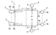
- FIG. 2 is a cross-sectional view schematically showing the bottom of the absorption tower and its peripheral part according to the embodiment of the present invention.
- FIG. 3 is a perspective view schematically showing the bottom of the absorption tower and the periphery thereof according to the embodiment of the present invention.
- a wet flue gas desulfurization apparatus (hereinafter referred to as “desulfurization apparatus”) according to an embodiment of the present invention will be described below.
- the desulfurization apparatus 1 includes a hollow absorption tower 2 formed in a substantially box shape.
- exhaust gas containing ion oxides (SO X ) such as sulfurous acid (sulfur dioxide, SO 2 ) is sent into the absorption tower 2, and the sent exhaust gas is desulfurized by the absorbing solution. It is discharged to the outside of the absorption tower 2 later.
- SO X ion oxides
- the desulfurization apparatus 1 employs a lime-gypsum method, in embodiments of the present invention, absorption liquid, limestone (calcium carbonate, CaCO 3) in limestone slurry was used as absorbent It has become.
- the desulfurization apparatus 1 includes a spray mechanism 3 that sprays the absorbing liquid into the absorption tower 2.
- the spray mechanism 3 includes a plurality of spray nozzles 3a.
- a header pipe 3b is connected to the plurality of spray nozzles 3a, and the absorbent s1 is sent from the header pipe 3b to the spray nozzle 3a.
- the absorption liquid s1 sprayed inside the absorption tower 2 is stored at the bottom of the absorption tower 2 (see the stored absorption liquid s2 in FIG. 1). Therefore, as shown in FIGS. 1 to 3, the desulfurization apparatus 1 is stored at the bottom of the absorption tower 2 because the absorption liquid s2 thus stored is used to desulfurize the exhaust gas inside the absorption tower 2.
- the absorption liquid s2 is sent to the upstream side (hereinafter referred to as “upstream side”) of the absorption liquid flow from the discharge nozzle 2a (see FIG. 3) formed at the bottom of the absorption tower 2 from the spray nozzle 3a of the header pipe 3b A circulation mechanism 4 is provided.
- the desulfurization apparatus 1 includes a plurality of oxidation mechanisms 5 that supply oxygen to the absorption liquid s2 stored inside the absorption tower 2 (see the supplied oxygen x in FIGS. 1 and 2).
- the desulfurization apparatus 1 includes a pair of liquid ejection mechanisms 6 that eject liquid to the absorption liquid s2 stored inside the absorption tower 2 (see the ejected water w in FIGS. 1 and 2).
- the liquid ejected from the mechanism 6 is water.
- the spray mechanism 3, the circulation mechanism 4, and the oxidation mechanism 5 are configured to start and stop together, and the liquid ejection mechanism 6 includes the spray mechanism 3, the circulation mechanism 4, and the oxidation mechanism 5. It can be started and stopped independently.
- the plurality of spray nozzles 3 a of the spray mechanism 3 are arranged at intervals in the absorbing liquid flow direction of the header pipe 3 b.
- the direction in which the spray nozzle 3a sprays the absorbing liquid is a direction from the bottom to the top.
- the header pipe 3b is formed to extend in the horizontal direction of the desulfurization apparatus 1.
- the circulation device 1 includes a circulation pipe 4a that connects the bottom of the absorption tower 2 and the upstream end of the header pipe 3b.
- a circulation pump 4b is attached to the circulation pipe 4a.
- the absorption liquid s2 stored at the bottom of the absorption tower 2 is pumped up by the circulation pump 4b and sent from the discharge port 2a of the absorption tower 2 (see FIG. 3) to the upstream end of the header pipe 3b through the circulation pipe 4a. Will be.
- the oxidation mechanism 5 is attached to the bottom side surface of the absorption tower 2.
- the oxidation mechanism 5 is disposed so as to be horizontally spaced from the outlet 2a of the absorption tower 2 and to face the outlet 2a.
- the oxidation mechanism 5 includes an oxygen supply pipe 5b extending from the oxidation mechanism main body 5a to the inside of the absorption tower 2. Oxygen x is sent from the oxidation mechanism main body 5a of the oxidation mechanism 5 to the absorption liquid s2 stored in the absorption tower 2 through the oxygen supply pipe 5b.
- the liquid ejection mechanism 6 includes a hydraulic nozzle 7 that ejects water w into the absorption tower 2.
- the hydraulic nozzle 7 has a liquid jet 7 a formed in a substantially circular shape, and water supplied to the hydraulic nozzle 7 passes through the liquid jet 7 a and the absorption tower 2. Will be sent to the inside.
- the pair of hydraulic nozzles 7 are respectively attached to the opposite side surfaces of the bottom of the absorption tower 2, and the liquid outlets 7 a of the pair of hydraulic nozzles 7 are arranged to face each other.
- the pair of hydraulic nozzles 7 are disposed on the discharge port 2 a side from the horizontal center position C between the discharge ports 2 a of the group of absorption towers 2 and the group of oxidation mechanisms 5.
- the hydraulic pressure ejection mechanism 6 includes a liquid supply pipe 8 that sends water from the outside of the absorption tower 2 to the hydraulic pressure nozzle 7.
- a liquid supply pump 9 is attached to the liquid supply pipe 8. The water pumped up at a predetermined pressure by the liquid supply pump 9 is sent from the outside of the absorption tower 2 to the hydraulic nozzle 7 through the liquid supply pipe 8 while maintaining the pumping pressure.
- the absorption liquid s2 stored at the bottom of the absorption tower 2 is pumped up by the pump 4b of the circulation mechanism 4 and sent to the upstream end of the header pipe 3b of the spray mechanism 3 through the circulation pipe 4a.
- the absorbing liquid sent to the header pipe 3b is sent to the spray nozzle 3a, and the absorbing liquid is sprayed into the absorption tower 2 by the spray nozzle 3a.
- the sprayed absorption liquid s1 reacts with the exhaust gas sent into the absorption tower 2 and absorbs sulfur oxides contained in the exhaust gas. Thereafter, the sprayed absorption liquid s1 falls and accumulates at the bottom of the absorption tower 2.
- the absorption liquid s2 stored at the bottom of the absorption tower 2 is pumped up by the pump 4b of the circulation mechanism 4, is sent again to the upstream end of the header pipe 3b through the circulation pipe 4a, and is used for desulfurization of exhaust gas. That is, the absorption liquid can be circulated through a path that goes around in order of the absorption tower 2, the circulation pipe 4 a, the header pipe 3 b, the spray nozzle 3 a, and the absorption tower 2. Further, the oxidation mechanism 5 supplies oxygen x from the oxygen supply port 5a to the absorption liquid s2 stored at the bottom of the absorption tower 2, and the absorption liquid s2 stored at the bottom of the absorption tower 2 is oxidized. .
- the liquid supply pump 9 pumps water outside the absorption tower 2 at a predetermined pressure.
- the pumped water is sent from the outside of the absorption tower 2 to the hydraulic nozzle 7 through the liquid supply pipe 8 while maintaining the pressure generated by the pumping.
- the water sent to the hydraulic nozzle 7 passes through the liquid supply port 7a of the hydraulic nozzle 7 and is ejected to the absorbing liquid s2 stored inside the absorption tower 2.
- the water w ejected from the hydraulic nozzle 7 generates a vortex in the absorbing liquid s2 stored in the absorption tower 2. Due to this vortex, the absorption liquid s2 stored inside the absorption tower 2 is stirred.
- the agitated absorbent is absorbed by such agitation. It will be pulverized and refined mainly between the outlet 2a of the tower 2 and the oxidation mechanism 5.
- the water w ejected from the hydraulic nozzle 7 generates a vortex in the absorption liquid s2 stored in the absorption tower 2, and the vortex flows.
- the absorbing liquid s2 stored in the absorption tower 2 is stirred. Therefore, when slurry sedimentation occurs, the eddy current caused by the water w ejected from the hydraulic nozzle 7 pulverizes and fines the absorbent that has settled around the discharge port 2a of the absorption tower 2 and the oxidation mechanism 5.
- the absorption liquid is sufficiently stirred particularly between the outlet 2a of the absorption tower 2 and the oxidation mechanism 5.
- the structure for stirring the absorbing liquid is a simple structure in which water w is ejected from the hydraulic nozzle 7 into the absorbing liquid
- the mechanism for stirring the absorbing liquid can be simplified.
- the mechanism for stirring the absorption liquid does not occupy the space inside the absorption tower 2, a wide space can be secured inside the absorption tower 2.
- maintenance inside the absorption tower 2 can be facilitated, and maintenance of the desulfurization apparatus 1 can be facilitated.
- the desulfurization apparatus 1 can be reduced in size.
- the specific gravity of the water w ejected from the hydraulic nozzle 7 is larger than the specific gravity of air conventionally used, the water w ejected from the hydraulic nozzle 7 is easily sent horizontally into the absorbing liquid. Therefore, it is possible to sufficiently agitate the absorbing liquid by ejecting water from the hydraulic nozzle 7 at a pressure lower than that conventionally applied to the air, generating a vortex in the absorbing liquid.
- the hydraulic nozzle 7 is disposed on the discharge port 2 a side from the horizontal center position C between the discharge port 2 a of the absorption tower 2 and the oxidation mechanism 5. Therefore, the settled absorbent is efficiently pulverized and refined around the outlet 2a of the absorption tower 2, which is the path of the circulating absorbent. Therefore, it is prevented that the path
- the liquid ejection mechanism 6 supplies the water pumped from the outside of the absorption tower 2 to the hydraulic nozzle 7 in a state where the pressure by the pumping is maintained. Since it is configured, a mechanism for feeding water to the hydraulic nozzle 7 like the liquid supply pipe 8 and the liquid supply pump 9 can be simplified, and a mechanism for stirring the absorbing liquid can be simplified.
- the liquid ejection mechanism 6 is configured to be able to start and stop independently from the spray mechanism 3, the circulation mechanism 4, and the oxidation mechanism 5. If the liquid ejection mechanism 6 is activated and operated before starting the spray mechanism 3, the circulation mechanism 4, and the oxidation mechanism 5, which are the main mechanisms of the apparatus 1, and the slurry sedimentation is eliminated, the desulfurization apparatus 1 becomes the spray mechanism. 3. It can be stably operated immediately after the circulation mechanism 4 and the oxidation mechanism 5 are started.
- the absorbent may be a slurry using slaked lime (calcium hydroxide, Ca (OH) 2 ), dolomite or the like as an absorbent.
- the desulfurization apparatus 1 may employ a magnesium hydroxide method, and in this case, the absorbent may be a slurry using magnesium hydroxide or the like as an absorbent.
- the desulfurization apparatus 1 may employ a sodium hydroxide method, and in this case, the absorbent may be a slurry using sodium hydroxide, sodium sulfate or the like as an absorbent.
- the desulfurization apparatus 1 may employ an ammonia absorption method, and in this case, the absorption liquid may be a slurry using ammonia or the like as an absorbent.
- the direction in which the spray nozzle 3a sprays the absorbing liquid may be a direction from the top to the bottom, a horizontal direction, an oblique direction, or the like.
- the header tube 3b may include a curved portion, a bent portion, a portion extending in the vertical direction, an inclined portion, and the like.
- the absorption tower 2 may be formed in a substantially cylindrical shape, a substantially conical shape, a substantially elliptical column shape, a substantially elliptical cone shape, a substantially polygonal shape, a substantially polygonal pyramid shape, or the like.
- the liquid ejected from the hydraulic nozzle 7 is a liquid other than water, for example, the same kind of liquid as the absorbent, or the same kind of liquid as before the absorbent is suspended in the absorbent. Etc.
- one or more liquid ejection mechanisms 6 may be provided on one side of the opposing side surfaces of the bottom of the absorption tower 2.
- a plurality of pairs of liquid ejection mechanisms 6 may be provided.
- the liquid ejection port 7a of the hydraulic nozzle 7 may be formed in a substantially semicircular shape, a substantially elliptical shape, a substantially semielliptical shape, a substantially polygonal shape, a substantially star shape, or the like.
- the liquid outlets 7a of the pair of hydraulic nozzles 7 may be arranged so as to be shifted in the height direction, the horizontal direction, and / or the circumferential direction of the absorption tower 2 with respect to each other. Good.
- the liquid ejection mechanism 6 allows liquid to be discharged from a liquid supply position spaced in the height direction of the absorption tower 2 with respect to the liquid level of the absorption liquid s2 stored at the bottom of the absorption tower 2.
- You may comprise so that the absorption liquid s2 stored in the bottom part of the absorption tower 2 may be stirred by making it fall naturally.
- the liquid supply position is the height direction of the absorption tower 2 with respect to the liquid level of the absorption liquid s2 stored at the bottom of the absorption tower 2 in order to achieve stirring of the absorption liquid s2 stored at the bottom of the absorption tower 2. It is preferable that the position is sufficiently spaced.
Landscapes
- Engineering & Computer Science (AREA)
- Chemical & Material Sciences (AREA)
- Environmental & Geological Engineering (AREA)
- Oil, Petroleum & Natural Gas (AREA)
- Chemical Kinetics & Catalysis (AREA)
- Analytical Chemistry (AREA)
- General Chemical & Material Sciences (AREA)
- Biomedical Technology (AREA)
- Health & Medical Sciences (AREA)
- Treating Waste Gases (AREA)
- Life Sciences & Earth Sciences (AREA)
- Hydrology & Water Resources (AREA)
- Water Supply & Treatment (AREA)
- Organic Chemistry (AREA)
- Gas Separation By Absorption (AREA)
Description
2 吸収塔
2a 排出口
3 噴霧機構
4 循環機構
5 酸化機構
6 液体噴出機構
7 液圧ノズル
s1,s2 吸収液
w 水
x 酸素
C 水平方向中心位置
Claims (4)
- 内部で排ガスを吸収液と気液接触させることによって脱硫させる吸収塔と、
前記吸収塔の内部に吸収液を噴霧する噴霧機構と、
前記吸収塔の底部に配置されると共に、前記吸収塔の内部に貯まる吸収液に酸素を供給する酸化機構と、
吸収液を前記吸収塔の底部に形成された排出口から前記噴霧機構に送る循環機構と、
前記吸収塔の内部に液体を噴出する液圧ノズルを有する液体噴出機構と
を備え、
前記酸化機構が、前記吸収塔の排出口に対して水平方向に間隔を空けて配置され、
前記液圧ノズルが、前記吸収塔の底部に取付けられ、かつ前記酸化機構と前記吸収塔の排出口との間に配置されている、湿式排煙脱硫装置。 - 前記液圧ノズルが、前記酸化機構と前記吸収塔の排出口との間における水平方向中心位置より前記排出口側に配置されている、請求項1に記載の湿式排煙脱硫装置。
- 前記液体噴出機構が、前記吸収塔の外部から汲み上げられた液体を、該汲み上げによる圧力を保持した状態で前記液圧ノズルに供給するように構成されている、請求項1に記載の湿式排煙脱硫装置。
- 前記液体噴出機構が、前記噴霧機構、前記酸化機構、及び前記循環機構から独立して起動かつ停止可能に構成されている、請求項3に記載の湿式排煙脱硫装置。
Priority Applications (7)
| Application Number | Priority Date | Filing Date | Title |
|---|---|---|---|
| KR1020157002036A KR101797327B1 (ko) | 2012-07-30 | 2013-07-10 | 습식 배연 탈황 장치 |
| JP2014528055A JP6227531B2 (ja) | 2012-07-30 | 2013-07-10 | 湿式排煙脱硫装置 |
| CN201380040179.7A CN104602787B (zh) | 2012-07-30 | 2013-07-10 | 湿式废气脱硫装置 |
| PL13825594T PL2881161T3 (pl) | 2012-07-30 | 2013-07-10 | Urządzenie do odsiarczania gazów spalinowych na mokro |
| EP13825594.8A EP2881161B1 (en) | 2012-07-30 | 2013-07-10 | Wet type exhaust gas desulfurization apparatus |
| ES13825594.8T ES2674920T3 (es) | 2012-07-30 | 2013-07-10 | Aparato de desulfuración de gas de escape de tipo húmedo |
| IN174DEN2015 IN2015DN00174A (ja) | 2012-07-30 | 2015-01-08 |
Applications Claiming Priority (2)
| Application Number | Priority Date | Filing Date | Title |
|---|---|---|---|
| US13/561,386 US9028762B2 (en) | 2012-07-30 | 2012-07-30 | Wet type exhaust gas desulfurization apparatus |
| US13/561,386 | 2012-07-30 |
Publications (1)
| Publication Number | Publication Date |
|---|---|
| WO2014021068A1 true WO2014021068A1 (ja) | 2014-02-06 |
Family
ID=49995085
Family Applications (1)
| Application Number | Title | Priority Date | Filing Date |
|---|---|---|---|
| PCT/JP2013/068845 Ceased WO2014021068A1 (ja) | 2012-07-30 | 2013-07-10 | 湿式排煙脱硫装置 |
Country Status (9)
| Country | Link |
|---|---|
| US (1) | US9028762B2 (ja) |
| EP (1) | EP2881161B1 (ja) |
| JP (1) | JP6227531B2 (ja) |
| KR (1) | KR101797327B1 (ja) |
| CN (1) | CN104602787B (ja) |
| ES (1) | ES2674920T3 (ja) |
| IN (1) | IN2015DN00174A (ja) |
| PL (1) | PL2881161T3 (ja) |
| WO (1) | WO2014021068A1 (ja) |
Cited By (1)
| Publication number | Priority date | Publication date | Assignee | Title |
|---|---|---|---|---|
| WO2020121552A1 (ja) * | 2018-12-11 | 2020-06-18 | 三菱日立パワーシステムズ株式会社 | 排ガス脱硫装置 |
Families Citing this family (5)
| Publication number | Priority date | Publication date | Assignee | Title |
|---|---|---|---|---|
| CN107213761A (zh) * | 2017-06-30 | 2017-09-29 | 成都川通达科技有限公司 | 一种新型脱硫塔 |
| CN108187473A (zh) * | 2018-02-05 | 2018-06-22 | 郑兴华 | 一种资源化脱硫系统 |
| CN108525496B (zh) * | 2018-04-26 | 2020-12-15 | 江苏蓝电环保股份有限公司 | 工业废气的硫化物净化处理方法 |
| CN109395543A (zh) * | 2018-12-31 | 2019-03-01 | 广东威特宝土壤修复科研中心有限公司 | 浸水式废气分离处理系统及方法 |
| CN110237670B (zh) * | 2019-06-27 | 2021-06-18 | 成都海成环保工程有限公司 | 一种采用双碱法循环脱硫系统及其脱硫工艺 |
Citations (4)
| Publication number | Priority date | Publication date | Assignee | Title |
|---|---|---|---|---|
| JPH07108131A (ja) * | 1993-10-08 | 1995-04-25 | Mitsubishi Heavy Ind Ltd | 排ガスの処理方法 |
| JPH07275654A (ja) * | 1993-11-10 | 1995-10-24 | Gottfried Bischoff Kompl Gasreinig Wasser Gmbh | 煙道廃ガスの脱硫装置における洗浄塔 |
| JPH10118451A (ja) * | 1996-10-17 | 1998-05-12 | Mitsubishi Heavy Ind Ltd | 排煙処理装置及び排煙処理方法 |
| JP2002210326A (ja) * | 2000-11-17 | 2002-07-30 | Mitsubishi Heavy Ind Ltd | 湿式排煙脱硫装置、及び、湿式排煙脱硫方法 |
Family Cites Families (17)
| Publication number | Priority date | Publication date | Assignee | Title |
|---|---|---|---|---|
| JPS58104619A (ja) * | 1981-12-15 | 1983-06-22 | Ishikawajima Harima Heavy Ind Co Ltd | 排煙脱硫装置の吸収塔 |
| DE3227187C1 (de) * | 1982-07-21 | 1988-12-01 | Gottfried Bischoff Bau kompl. Gasreinigungs- und Wasserrückkühlanlagen GmbH & Co KG, 4300 Essen | Waschturm fuer eine Anlage zur Entschwefelung von Rauchgas |
| JPH0773657B2 (ja) * | 1986-08-07 | 1995-08-09 | 三菱重工業株式会社 | 湿式排煙脱硫方法 |
| JPH0555176A (ja) | 1991-08-26 | 1993-03-05 | Sony Corp | ドライエツチング方法 |
| JP2989484B2 (ja) * | 1994-08-18 | 1999-12-13 | 三菱重工業株式会社 | 湿式排煙脱硫装置 |
| JP3170158B2 (ja) | 1994-11-08 | 2001-05-28 | 三菱重工業株式会社 | 気液接触装置及び湿式排煙脱硫装置 |
| US5676716A (en) * | 1995-10-30 | 1997-10-14 | The Babcock & Wilcox Company | Apparatus for mixing a tank and improving air/liquid contact in an oxidized system |
| JP3676020B2 (ja) * | 1997-02-26 | 2005-07-27 | バブコック日立株式会社 | 湿式排煙脱硫装置 |
| DE69716942D1 (de) * | 1997-10-07 | 2002-12-12 | Nippon Kokan Kk | Verfahren zur nassentschwefelung von abgasen |
| DE69921605T2 (de) | 1998-08-11 | 2005-08-04 | Mitsubishi Heavy Industries, Ltd. | Vorrichtung zur nassentschwefelung von abgasen |
| JP2002361035A (ja) | 2001-06-06 | 2002-12-17 | Babcock Hitachi Kk | ボイラ排煙処理装置 |
| JP2003170039A (ja) * | 2001-12-10 | 2003-06-17 | Ishikawajima Harima Heavy Ind Co Ltd | 反応装置 |
| JP4734537B2 (ja) * | 2005-05-24 | 2011-07-27 | 川崎重工業株式会社 | 排煙脱硫装置の吸収塔 |
| JP5046755B2 (ja) * | 2007-06-27 | 2012-10-10 | 三菱重工業株式会社 | 気液接触装置 |
| CN101185839B (zh) * | 2007-09-10 | 2010-09-01 | 中电投远达环保工程有限公司 | 湿法烟气脱硫射流氧化系统 |
| JP2011005448A (ja) * | 2009-06-26 | 2011-01-13 | Mitsubishi Heavy Ind Ltd | 河川水利用排煙脱硫システム及び腐植物質除去方法 |
| CN101844036A (zh) * | 2010-05-11 | 2010-09-29 | 上海龙净环保科技工程有限公司 | 塔内氧化-钙基强碱-石膏湿法烟气脱硫工艺 |
-
2012
- 2012-07-30 US US13/561,386 patent/US9028762B2/en not_active Expired - Fee Related
-
2013
- 2013-07-10 CN CN201380040179.7A patent/CN104602787B/zh not_active Expired - Fee Related
- 2013-07-10 JP JP2014528055A patent/JP6227531B2/ja not_active Expired - Fee Related
- 2013-07-10 PL PL13825594T patent/PL2881161T3/pl unknown
- 2013-07-10 KR KR1020157002036A patent/KR101797327B1/ko not_active Expired - Fee Related
- 2013-07-10 WO PCT/JP2013/068845 patent/WO2014021068A1/ja not_active Ceased
- 2013-07-10 ES ES13825594.8T patent/ES2674920T3/es active Active
- 2013-07-10 EP EP13825594.8A patent/EP2881161B1/en not_active Not-in-force
-
2015
- 2015-01-08 IN IN174DEN2015 patent/IN2015DN00174A/en unknown
Patent Citations (4)
| Publication number | Priority date | Publication date | Assignee | Title |
|---|---|---|---|---|
| JPH07108131A (ja) * | 1993-10-08 | 1995-04-25 | Mitsubishi Heavy Ind Ltd | 排ガスの処理方法 |
| JPH07275654A (ja) * | 1993-11-10 | 1995-10-24 | Gottfried Bischoff Kompl Gasreinig Wasser Gmbh | 煙道廃ガスの脱硫装置における洗浄塔 |
| JPH10118451A (ja) * | 1996-10-17 | 1998-05-12 | Mitsubishi Heavy Ind Ltd | 排煙処理装置及び排煙処理方法 |
| JP2002210326A (ja) * | 2000-11-17 | 2002-07-30 | Mitsubishi Heavy Ind Ltd | 湿式排煙脱硫装置、及び、湿式排煙脱硫方法 |
Cited By (2)
| Publication number | Priority date | Publication date | Assignee | Title |
|---|---|---|---|---|
| WO2020121552A1 (ja) * | 2018-12-11 | 2020-06-18 | 三菱日立パワーシステムズ株式会社 | 排ガス脱硫装置 |
| JP2020093191A (ja) * | 2018-12-11 | 2020-06-18 | 三菱日立パワーシステムズ株式会社 | 排ガス脱硫装置 |
Also Published As
| Publication number | Publication date |
|---|---|
| JP6227531B2 (ja) | 2017-11-08 |
| IN2015DN00174A (ja) | 2015-06-12 |
| US20140030157A1 (en) | 2014-01-30 |
| CN104602787A (zh) | 2015-05-06 |
| CN104602787B (zh) | 2017-07-04 |
| EP2881161B1 (en) | 2018-06-20 |
| ES2674920T3 (es) | 2018-07-05 |
| EP2881161A1 (en) | 2015-06-10 |
| KR20150024924A (ko) | 2015-03-09 |
| EP2881161A4 (en) | 2015-08-12 |
| US9028762B2 (en) | 2015-05-12 |
| KR101797327B1 (ko) | 2017-11-13 |
| JPWO2014021068A1 (ja) | 2016-07-21 |
| PL2881161T3 (pl) | 2018-10-31 |
Similar Documents
| Publication | Publication Date | Title |
|---|---|---|
| JP6227531B2 (ja) | 湿式排煙脱硫装置 | |
| CN1083290C (zh) | 采用固体脱硫剂的湿式烟道气脱硫设备和方法 | |
| US5779999A (en) | Method for scrubbing flue gases | |
| US6787114B2 (en) | Method and apparatus for wet type flue-gas desulfurization | |
| ES2360558T3 (es) | Aparato para la desulfuración por vía húmeda de los gases de combustión, y método de desulfuración por vía húmeda de los gases de combustión. | |
| US10661222B1 (en) | Flue gas desulfurization system | |
| JP2000210532A (ja) | 排煙脱硫装置 | |
| TWI513501B (zh) | Exhaust gas treatment device | |
| JP4734537B2 (ja) | 排煙脱硫装置の吸収塔 | |
| JP2006255629A (ja) | 排煙脱硫装置 | |
| JP3842706B2 (ja) | 湿式排煙脱硫装置と方法 | |
| CN101837240A (zh) | 脱硫系统 | |
| JP3590856B2 (ja) | 排ガスの脱硫方法 | |
| JPH09206549A (ja) | 湿式排煙脱硫装置 | |
| JP2000317259A (ja) | 排煙脱硫装置 | |
| KR200309272Y1 (ko) | 탈황 설비의 덕트 파이프 세정 장치 | |
| JPS62183841A (ja) | 湿式排煙脱硫装置 | |
| JP2002113324A (ja) | 湿式石灰石膏法脱硫方法及び装置 | |
| JP2001198583A (ja) | 被処理液酸化方法と酸化装置 | |
| MXPA96002039A (en) | Procedure for the deulfuration of degreased gas containing sulfur acid gas | |
| JP2011194296A (ja) | 排煙脱硫装置 |
Legal Events
| Date | Code | Title | Description |
|---|---|---|---|
| 121 | Ep: the epo has been informed by wipo that ep was designated in this application |
Ref document number: 13825594 Country of ref document: EP Kind code of ref document: A1 |
|
| ENP | Entry into the national phase |
Ref document number: 20157002036 Country of ref document: KR Kind code of ref document: A |
|
| ENP | Entry into the national phase |
Ref document number: 2014528055 Country of ref document: JP Kind code of ref document: A |
|
| WWE | Wipo information: entry into national phase |
Ref document number: 2013825594 Country of ref document: EP |
|
| NENP | Non-entry into the national phase |
Ref country code: DE |