WO2014024697A1 - スピンモータ及びスピン回転部材 - Google Patents
スピンモータ及びスピン回転部材 Download PDFInfo
- Publication number
- WO2014024697A1 WO2014024697A1 PCT/JP2013/070216 JP2013070216W WO2014024697A1 WO 2014024697 A1 WO2014024697 A1 WO 2014024697A1 JP 2013070216 W JP2013070216 W JP 2013070216W WO 2014024697 A1 WO2014024697 A1 WO 2014024697A1
- Authority
- WO
- WIPO (PCT)
- Prior art keywords
- spin
- substrate
- injector
- rotor
- rotator
- Prior art date
- Legal status (The legal status is an assumption and is not a legal conclusion. Google has not performed a legal analysis and makes no representation as to the accuracy of the status listed.)
- Ceased
Links
Images
Classifications
-
- H—ELECTRICITY
- H02—GENERATION; CONVERSION OR DISTRIBUTION OF ELECTRIC POWER
- H02N—ELECTRIC MACHINES NOT OTHERWISE PROVIDED FOR
- H02N11/00—Generators or motors not provided for elsewhere; Alleged perpetua mobilia obtained by electric or magnetic means
-
- H—ELECTRICITY
- H02—GENERATION; CONVERSION OR DISTRIBUTION OF ELECTRIC POWER
- H02K—DYNAMO-ELECTRIC MACHINES
- H02K1/00—Details of the magnetic circuit
- H02K1/06—Details of the magnetic circuit characterised by the shape, form or construction
- H02K1/22—Rotating parts of the magnetic circuit
- H02K1/27—Rotor cores with permanent magnets
-
- H—ELECTRICITY
- H02—GENERATION; CONVERSION OR DISTRIBUTION OF ELECTRIC POWER
- H02K—DYNAMO-ELECTRIC MACHINES
- H02K1/00—Details of the magnetic circuit
- H02K1/06—Details of the magnetic circuit characterised by the shape, form or construction
- H02K1/12—Stationary parts of the magnetic circuit
-
- H—ELECTRICITY
- H02—GENERATION; CONVERSION OR DISTRIBUTION OF ELECTRIC POWER
- H02N—ELECTRIC MACHINES NOT OTHERWISE PROVIDED FOR
- H02N1/00—Electrostatic generators or motors using a solid moving electrostatic charge carrier
- H02N1/002—Electrostatic motors
-
- H—ELECTRICITY
- H02—GENERATION; CONVERSION OR DISTRIBUTION OF ELECTRIC POWER
- H02N—ELECTRIC MACHINES NOT OTHERWISE PROVIDED FOR
- H02N15/00—Holding or levitation devices using magnetic attraction or repulsion, not otherwise provided for
-
- H—ELECTRICITY
- H10—SEMICONDUCTOR DEVICES; ELECTRIC SOLID-STATE DEVICES NOT OTHERWISE PROVIDED FOR
- H10D—INORGANIC ELECTRIC SEMICONDUCTOR DEVICES
- H10D48/00—Individual devices not covered by groups H10D1/00 - H10D44/00
- H10D48/385—Devices using spin-polarised carriers
Definitions
- the present invention relates to a spin motor and a spin rotating member.
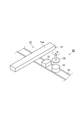
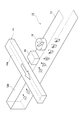
- FIG. 2 is a cross-sectional view taken along line II-II in FIG. It is the perspective view which showed the spin motor which concerns on one Embodiment. It is a schematic diagram explaining the principle of operation of the spin rotation member concerning one embodiment.
- the spin motor according to the present embodiment is a spin motor that applies a so-called spin valve structure, and is suitably employed, for example, as a nanoscale spin motor.
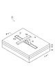
- FIG. 1 is a perspective view of a spin rotating member used in a spin motor according to an embodiment.
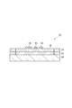
- FIG. 2 is a sectional view taken along line II-II in FIG.
- the spin current arriving at the spin rotator 16 has its spin direction rotated by ⁇ in the in-plane direction of the substrate in time series.
- the spin of the channel unit 12 gives a spin transfer torque to the magnetic moment of the spin rotor 16.
- the magnetic moment of the spin rotator 16 is rotated by rotating the spin direction of the spin current in time series.
- the motor rotor 30 rotates following the magnetic moment of the spin rotor 16.
- the spin motor 40 can be driven by converting the rotation of the magnetic moment into kinetic energy.
- the horizontal cross section of the spin rotator 16 has an elliptical shape such as an elliptical shape, the magnetic moment is easily oriented in the major axis direction. Can be controlled.
- the spin rotating member 10 and the spin motor 40 according to the embodiment can be manufactured by stacking, etching, and the like on the substrate 24, and thus can be easily manufactured by conventional semiconductor technology.
- the spin rotor 16 is formed so that the width in the direction orthogonal to the longitudinal direction of the channel portion 12 is equal to or smaller than the line width of the channel portion 12.
- the angular momentum of the spin of the channel portion 12 can be efficiently propagated to the spin rotor 16.
- a controller that changes the voltage value applied to the spin injector 14 may be adopted as the spin rotation controller 15.
- a Schottky barrier is formed at the interface between the ferromagnetic metal and the semiconductor, and a large current flows when the electron energy and the resonance level coincide. Since the resonance level generated in the ferromagnetic metal / semiconductor interface can be changed by changing the voltage value applied to the spin injector 14, the spin direction of the channel portion 12 is changed to the spin injector. The applied voltage can be controlled. By forming in this way, the number of parts brought into contact with the channel portion 12 can be reduced.
Landscapes
- Engineering & Computer Science (AREA)
- Chemical & Material Sciences (AREA)
- Combustion & Propulsion (AREA)
- Power Engineering (AREA)
- Micromachines (AREA)
- Hall/Mr Elements (AREA)
Abstract
Description
Claims (10)
- 基板と、
前記基板上に設けられ、基板面内方向に磁化された強磁性体からなるスピン注入子と、
前記基板上に前記スピン注入子と離間して設けられ、基板面内方向に磁気モーメントが回転可能な強磁性体からなる円板状のスピン回転子と、
前記スピン注入子と前記スピン回転子との間に配置され、前記スピン注入子及び前記スピン回転子と直接又は絶縁層を介して接合された非磁性体からなるチャネル部と、
前記チャネル部のスピンの回転方向を制御するスピン回転制御部と、
を備えるスピン回転部材。 - 前記スピン回転制御部は、前記チャネル部と直接又は絶縁層を介して接合され、前記チャネル部へ電圧を印加する請求項1に記載のスピン回転部材。
- 前記スピン回転制御部は、円偏光を前記チャネル部へ照射する請求項1に記載のスピン回転部材。
- 前記スピン回転制御部は、前記スピン注入子へ印加する電圧値を変更する請求項1に記載のスピン回転部材。
- 前記チャネル部は、半導体材料により形成される請求項1~4の何れか一項に記載のスピン回転部材。
- 前記チャネル部は、二次元電子ガス層を有する請求項1~5の何れか一項に記載のスピン回転部材。
- 前記チャネル部は、軸線方向が面内方向に向くように配置された線形部材であって、
前記スピン回転子は、その直径が前記チャネル部の線幅より小さい請求項1~6の何れか一項に記載のスピン回転部材。 - 基板と、
前記基板上に設けられ、基板面内方向に磁化された強磁性体からなるスピン注入子と、
前記基板上に前記スピン注入子と離間して設けられ、基板面内方向に磁気モーメントが回転可能な強磁性体からなるスピン回転子と、
前記スピン注入子と前記スピン回転子との間に配置され、前記スピン注入子及び前記スピン回転子と直接又は絶縁層を介して接合された非磁性体からなるチャネル部と、
前記チャネル部のスピンの回転方向を制御するスピン回転制御部と、
前記スピン回転子と離間し対向して配置され、前記スピン回転子の磁気モーメントに追従して回転する強磁性体からなるモータ回転子と、
を備えるスピンモータ。 - 前記スピン回転子は、円板状を呈し、
前記モータ回転子は、回転軸が基板に直交するように配置される請求項8に記載のスピンモータ。 - 前記チャネル部は、前記基板上に形成され、
前記スピン注入子及び前記スピン回転子は、前記チャネル部上に形成され、
前記モータ回転子は、前記スピン回転子の上方に離間して配置される請求項8又は9に記載のスピンモータ。
Priority Applications (5)
| Application Number | Priority Date | Filing Date | Title |
|---|---|---|---|
| EP13828477.3A EP2884654B1 (en) | 2012-08-09 | 2013-07-25 | Spin motor and spin rotary member |
| JP2013554509A JP5534493B1 (ja) | 2012-08-09 | 2013-07-25 | スピンモータ及びスピン回転部材 |
| US14/420,516 US9548634B2 (en) | 2012-08-09 | 2013-07-25 | Spin motor and rotary member |
| KR1020157005532A KR101633694B1 (ko) | 2012-08-09 | 2013-07-25 | 스핀 모터 및 스핀 회전 부재 |
| CN201380041909.5A CN104584416B (zh) | 2012-08-09 | 2013-07-25 | 自旋马达及自旋旋转构件 |
Applications Claiming Priority (2)
| Application Number | Priority Date | Filing Date | Title |
|---|---|---|---|
| JP2012-177339 | 2012-08-09 | ||
| JP2012177339 | 2012-08-09 |
Publications (1)
| Publication Number | Publication Date |
|---|---|
| WO2014024697A1 true WO2014024697A1 (ja) | 2014-02-13 |
Family
ID=50067930
Family Applications (1)
| Application Number | Title | Priority Date | Filing Date |
|---|---|---|---|
| PCT/JP2013/070216 Ceased WO2014024697A1 (ja) | 2012-08-09 | 2013-07-25 | スピンモータ及びスピン回転部材 |
Country Status (7)
| Country | Link |
|---|---|
| US (1) | US9548634B2 (ja) |
| EP (1) | EP2884654B1 (ja) |
| JP (1) | JP5534493B1 (ja) |
| KR (1) | KR101633694B1 (ja) |
| CN (1) | CN104584416B (ja) |
| TW (1) | TWI545883B (ja) |
| WO (1) | WO2014024697A1 (ja) |
Cited By (1)
| Publication number | Priority date | Publication date | Assignee | Title |
|---|---|---|---|---|
| EP3300120A4 (en) * | 2015-05-22 | 2018-12-26 | Japan Science and Technology Agency | Pulse generation device |
Families Citing this family (3)
| Publication number | Priority date | Publication date | Assignee | Title |
|---|---|---|---|---|
| KR101827294B1 (ko) * | 2013-10-31 | 2018-02-08 | 고쿠리츠켄큐카이하츠호진 카가쿠기쥬츠신코키코 | 스핀 제어 기구 및 스핀 디바이스 |
| CN105197870B (zh) * | 2015-09-30 | 2017-03-22 | 西交利物浦大学 | 自旋极化电流驱动的亚微米/纳米马达及其制作方法 |
| JP6625281B1 (ja) * | 2018-09-12 | 2019-12-25 | Tdk株式会社 | リザボア素子及びニューロモルフィック素子 |
Citations (4)
| Publication number | Priority date | Publication date | Assignee | Title |
|---|---|---|---|---|
| JP2001358379A (ja) * | 2000-06-12 | 2001-12-26 | Fujitsu Ltd | 磁気検出素子 |
| JP2006345638A (ja) | 2005-06-08 | 2006-12-21 | Kyoto Univ | ジャイロ磁気モータ |
| JP2007069325A (ja) | 2005-09-08 | 2007-03-22 | Japan Science & Technology Agency | 微小電磁装置の作製方法及びそれによって作製される微小電磁装置 |
| WO2008123023A1 (ja) * | 2007-03-16 | 2008-10-16 | Keio University | スピン緩和変動方法、スピン流検出方法、及び、スピン緩和を利用したスピントロニクスデバイス |
Family Cites Families (7)
| Publication number | Priority date | Publication date | Assignee | Title |
|---|---|---|---|---|
| JPH05300758A (ja) * | 1992-04-20 | 1993-11-12 | Fujitsu Ltd | マイクロモータ |
| US5883454A (en) | 1996-06-28 | 1999-03-16 | Creative Gifts, Inc. | Electormagnetic drive method and apparatus for driving a rotationally stabilized magnetically levitated object |
| US6137206A (en) | 1999-03-23 | 2000-10-24 | Cronos Integrated Microsystems, Inc. | Microelectromechanical rotary structures |
| GB0022328D0 (en) | 2000-09-12 | 2000-10-25 | Univ Cambridge Tech | An optically addressed spin-polarised diode |
| JP3621367B2 (ja) * | 2001-09-17 | 2005-02-16 | 株式会社東芝 | スピントランジスタ |
| US20100157662A1 (en) * | 2005-04-26 | 2010-06-24 | Teruo Ono | Mram and method for writing in mram |
| WO2012070217A1 (ja) * | 2010-11-22 | 2012-05-31 | パナソニック株式会社 | スピン注入電極の製造方法 |
-
2013
- 2013-07-25 JP JP2013554509A patent/JP5534493B1/ja active Active
- 2013-07-25 KR KR1020157005532A patent/KR101633694B1/ko not_active Expired - Fee Related
- 2013-07-25 CN CN201380041909.5A patent/CN104584416B/zh active Active
- 2013-07-25 WO PCT/JP2013/070216 patent/WO2014024697A1/ja not_active Ceased
- 2013-07-25 US US14/420,516 patent/US9548634B2/en active Active
- 2013-07-25 EP EP13828477.3A patent/EP2884654B1/en not_active Not-in-force
- 2013-08-07 TW TW102128253A patent/TWI545883B/zh not_active IP Right Cessation
Patent Citations (4)
| Publication number | Priority date | Publication date | Assignee | Title |
|---|---|---|---|---|
| JP2001358379A (ja) * | 2000-06-12 | 2001-12-26 | Fujitsu Ltd | 磁気検出素子 |
| JP2006345638A (ja) | 2005-06-08 | 2006-12-21 | Kyoto Univ | ジャイロ磁気モータ |
| JP2007069325A (ja) | 2005-09-08 | 2007-03-22 | Japan Science & Technology Agency | 微小電磁装置の作製方法及びそれによって作製される微小電磁装置 |
| WO2008123023A1 (ja) * | 2007-03-16 | 2008-10-16 | Keio University | スピン緩和変動方法、スピン流検出方法、及び、スピン緩和を利用したスピントロニクスデバイス |
Non-Patent Citations (1)
| Title |
|---|
| See also references of EP2884654A4 |
Cited By (1)
| Publication number | Priority date | Publication date | Assignee | Title |
|---|---|---|---|---|
| EP3300120A4 (en) * | 2015-05-22 | 2018-12-26 | Japan Science and Technology Agency | Pulse generation device |
Also Published As
| Publication number | Publication date |
|---|---|
| US9548634B2 (en) | 2017-01-17 |
| CN104584416A (zh) | 2015-04-29 |
| EP2884654B1 (en) | 2016-10-19 |
| KR101633694B1 (ko) | 2016-06-27 |
| JP5534493B1 (ja) | 2014-07-02 |
| TW201414175A (zh) | 2014-04-01 |
| EP2884654A1 (en) | 2015-06-17 |
| CN104584416B (zh) | 2017-05-03 |
| JPWO2014024697A1 (ja) | 2016-07-25 |
| TWI545883B (zh) | 2016-08-11 |
| EP2884654A4 (en) | 2015-08-12 |
| KR20150045455A (ko) | 2015-04-28 |
| US20150229169A1 (en) | 2015-08-13 |
Similar Documents
| Publication | Publication Date | Title |
|---|---|---|
| JP5534493B1 (ja) | スピンモータ及びスピン回転部材 | |
| JP2007525937A5 (ja) | ||
| JP5569851B2 (ja) | スピン偏極トランジスタ素子 | |
| CN113192718B (zh) | 用于生成磁场的方法和设备 | |
| JP6090878B2 (ja) | スピン制御機構及びスピンデバイス | |
| JP5817260B2 (ja) | 磁気ギア装置 | |
| Cugat et al. | Novel magnetic micro-actuators and systems (MAGMAS) using permanent magnets | |
| KR101702035B1 (ko) | 영구자석의 자기력선 제어를 이용한 모터 | |
| CN107612253A (zh) | 用于多自由度电磁机器的输入调幅控制 | |
| US8779637B2 (en) | Magnetic actuation method | |
| Fujiwara et al. | Micrometer scale magnetization of neodymium magnet for integrated magnetic MEMS | |
| JP6436426B2 (ja) | パルス生成装置 | |
| JP2001268957A (ja) | 回転体と量子電動機 | |
| KR101931633B1 (ko) | 회전자계형 유도전자펌프 | |
| JP2016144276A (ja) | 電磁アクチュエータ、羽根駆動装置、及びカメラ | |
| JP6322055B2 (ja) | 双安定移動装置 | |
| JP2015116027A (ja) | リニアモータ | |
| JPH05227712A (ja) | 直流電動機 | |
| JP2013094018A (ja) | 反磁性アクチュエータ |
Legal Events
| Date | Code | Title | Description |
|---|---|---|---|
| ENP | Entry into the national phase |
Ref document number: 2013554509 Country of ref document: JP Kind code of ref document: A |
|
| 121 | Ep: the epo has been informed by wipo that ep was designated in this application |
Ref document number: 13828477 Country of ref document: EP Kind code of ref document: A1 |
|
| NENP | Non-entry into the national phase |
Ref country code: DE |
|
| WWE | Wipo information: entry into national phase |
Ref document number: 14420516 Country of ref document: US |
|
| REEP | Request for entry into the european phase |
Ref document number: 2013828477 Country of ref document: EP |
|
| WWE | Wipo information: entry into national phase |
Ref document number: 2013828477 Country of ref document: EP |
|
| ENP | Entry into the national phase |
Ref document number: 20157005532 Country of ref document: KR Kind code of ref document: A |