WO2014027548A1 - 内視鏡用処置具 - Google Patents
内視鏡用処置具 Download PDFInfo
- Publication number
- WO2014027548A1 WO2014027548A1 PCT/JP2013/070048 JP2013070048W WO2014027548A1 WO 2014027548 A1 WO2014027548 A1 WO 2014027548A1 JP 2013070048 W JP2013070048 W JP 2013070048W WO 2014027548 A1 WO2014027548 A1 WO 2014027548A1
- Authority
- WO
- WIPO (PCT)
- Prior art keywords
- needle tube
- cup
- tissue
- sampling member
- needle
- Prior art date
- Legal status (The legal status is an assumption and is not a legal conclusion. Google has not performed a legal analysis and makes no representation as to the accuracy of the status listed.)
- Ceased
Links
Images






Classifications
-
- A—HUMAN NECESSITIES
- A61—MEDICAL OR VETERINARY SCIENCE; HYGIENE
- A61B—DIAGNOSIS; SURGERY; IDENTIFICATION
- A61B10/00—Instruments for taking body samples for diagnostic purposes; Other methods or instruments for diagnosis, e.g. for vaccination diagnosis, sex determination or ovulation-period determination; Throat striking implements
- A61B10/02—Instruments for taking cell samples or for biopsy
- A61B10/04—Endoscopic instruments, e.g. catheter-type instruments
-
- A—HUMAN NECESSITIES
- A61—MEDICAL OR VETERINARY SCIENCE; HYGIENE
- A61B—DIAGNOSIS; SURGERY; IDENTIFICATION
- A61B10/00—Instruments for taking body samples for diagnostic purposes; Other methods or instruments for diagnosis, e.g. for vaccination diagnosis, sex determination or ovulation-period determination; Throat striking implements
- A61B10/02—Instruments for taking cell samples or for biopsy
- A61B10/0233—Pointed or sharp biopsy instruments
- A61B10/0266—Pointed or sharp biopsy instruments means for severing sample
-
- A—HUMAN NECESSITIES
- A61—MEDICAL OR VETERINARY SCIENCE; HYGIENE
- A61B—DIAGNOSIS; SURGERY; IDENTIFICATION
- A61B10/00—Instruments for taking body samples for diagnostic purposes; Other methods or instruments for diagnosis, e.g. for vaccination diagnosis, sex determination or ovulation-period determination; Throat striking implements
- A61B10/02—Instruments for taking cell samples or for biopsy
- A61B10/0233—Pointed or sharp biopsy instruments
- A61B10/0266—Pointed or sharp biopsy instruments means for severing sample
- A61B10/0275—Pointed or sharp biopsy instruments means for severing sample with sample notch, e.g. on the side of inner stylet
-
- A—HUMAN NECESSITIES
- A61—MEDICAL OR VETERINARY SCIENCE; HYGIENE
- A61B—DIAGNOSIS; SURGERY; IDENTIFICATION
- A61B10/00—Instruments for taking body samples for diagnostic purposes; Other methods or instruments for diagnosis, e.g. for vaccination diagnosis, sex determination or ovulation-period determination; Throat striking implements
- A61B10/02—Instruments for taking cell samples or for biopsy
- A61B10/06—Biopsy forceps, e.g. with cup-shaped jaws
-
- A—HUMAN NECESSITIES
- A61—MEDICAL OR VETERINARY SCIENCE; HYGIENE
- A61B—DIAGNOSIS; SURGERY; IDENTIFICATION
- A61B10/00—Instruments for taking body samples for diagnostic purposes; Other methods or instruments for diagnosis, e.g. for vaccination diagnosis, sex determination or ovulation-period determination; Throat striking implements
- A61B10/02—Instruments for taking cell samples or for biopsy
- A61B10/04—Endoscopic instruments, e.g. catheter-type instruments
- A61B2010/045—Needles
-
- A—HUMAN NECESSITIES
- A61—MEDICAL OR VETERINARY SCIENCE; HYGIENE
- A61B—DIAGNOSIS; SURGERY; IDENTIFICATION
- A61B17/00—Surgical instruments, devices or methods
- A61B17/32—Surgical cutting instruments
- A61B17/3205—Excision instruments
- A61B17/3207—Atherectomy devices working by cutting or abrading; Similar devices specially adapted for non-vascular obstructions
- A61B17/320783—Atherectomy devices working by cutting or abrading; Similar devices specially adapted for non-vascular obstructions through side-hole, e.g. sliding or rotating cutter inside catheter
- A61B2017/320791—Atherectomy devices working by cutting or abrading; Similar devices specially adapted for non-vascular obstructions through side-hole, e.g. sliding or rotating cutter inside catheter with cutter extending outside the cutting window
Definitions
- the present invention relates to an endoscopic treatment tool, and more particularly to an endoscopic treatment tool for puncturing a tissue and collecting a tissue for biopsy.
- Patent Literature 1 describes a biopsy tool including a cup.
- the cup is provided at the distal end of a long insertion portion to be inserted into the body and functions as a tissue collection unit.
- a curved direction adjusting mechanism having a joint is provided on the proximal end side of the cup.
- Patent Document 2 describes a biopsy tool including a forceps cup.
- a needle-like portion is formed at the tip of the forceps cup and can be opened and closed. Opening and closing of the forceps cup is performed by advancing and retracting the operation wire.
- the biopsy tool described in Patent Document 1 can collect tissue in a soft tissue.
- the direction adjustment mechanism is provided, there is a problem that even if the tip of the cup is sharpened, the joint bends when trying to puncture, and it is not easy to puncture the tissue.
- the biopsy tool described in Patent Document 2 can puncture relatively hard tissue, it is necessary to first open a forceps cup in the tissue in order to collect the tissue.
- the operation of opening the forceps cup is performed by the advancement of the operation wire.
- the operation wire is inferior in compression resistance, the force transmission by the advancement is not good, and a large force cannot be generated in the forceps cup. Therefore, in a state where a large amount of tissue exists around the puncture, there is a problem that the cup is difficult to open and the procedure may be complicated.
- the present invention has been made in view of the above problems, and it is not necessary to project the cup part greatly from the needle tube in the tissue before collecting the tissue, and the tissue is suitably collected by an easy operation.
- An object of the present invention is to provide an endoscopic treatment tool.
- the endoscope treatment tool includes a puncture portion and a side hole provided on the outer peripheral surface of the puncture portion and communicating with the lumen.
- a needle tube that is flexible and is formed in a long shape, a sampling member that is accommodated in the lumen and that opens toward the radially outer side of the needle tube, and the sampling An operation member connected to the member and inserted into the needle tube so as to be able to advance and retreat. When the operation member is moved with respect to the needle tube, the cup portion protrudes from the side hole.
- the sampling member is attached to the needle tube via a rotation shaft, and is rotatable about the rotation shaft. Good.
- the sampling member has the cup portion at a first end in the longitudinal direction of the sampling member, and an intermediate portion in the longitudinal direction is
- a second end of the sampling member in the longitudinal direction protrudes from a second side hole formed in the needle tube. Also good.
- the rotation axis only needs to be located between the cup portion and the base end side of the sampling member in the longitudinal direction of the sampling member.
- a fifth aspect of the present invention in the fourth aspect, further comprising a second cup portion provided at the second end portion of the sampling member and opening toward a radially outer side of the needle tube. It may be.
- a link for connecting the sampling member and the operation member may be further provided.
- a cutting portion provided on the needle tube and in contact with the rotated cup portion may be further provided.
- FIG. 1 It is a figure which shows the whole structure of the biopsy needle which is a treatment tool for endoscopes of 1st embodiment of this invention. It is sectional drawing of the front-end
- FIG. 1 is a diagram illustrating an overall configuration of a biopsy needle 1 which is a treatment instrument for an endoscope according to the present embodiment.
- the biopsy needle 1 includes a long needle tube 10 having flexibility, a sheath 40 through which the needle tube 10 is inserted so as to be able to advance and retreat, and an operation unit 50 attached to a proximal end portion of the needle tube 10.
- the needle tube 10 is made of a metal such as stainless steel and has a hollow shape, and has a flexible outer diameter, for example, about 0.5 to 2 millimeters (mm).
- the tip of the needle tube 10 is formed in a conical shape.
- the conical tip portion is a sharp puncture portion 11 that is inserted into a tissue to be biopsied.
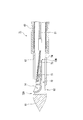
- FIG. 2 is a cross-sectional view of the distal end portion of the needle tube 10 and its periphery.
- a side hole 12 communicating with the lumen is provided on the outer peripheral surface of the needle tube 10.
- a collection member 13 for collecting tissue is disposed in the lumen of the needle tube 10.
- the first end portion 13A of the collection member 13 is provided with a cup portion 14 having an accommodation space in which the collected tissue is accommodated.
- the peripheral edge 14A of the cup portion 14 serving as the opening of the accommodation space has a sharp cutting edge shape, and can easily separate tissue.
- the second end portion 13 ⁇ / b> B located on the opposite side of the first end portion 13 ⁇ / b> A of the sampling member 13 is a rotation shaft 15 attached so as to penetrate the needle tube 10 in the radial direction. And is rotatable about a rotation shaft 15.
- the sampling member 13 is attached so that the first end portion 13A provided with the cup portion 14 is on the puncture portion 11 side, and the opening of the cup portion 14 faces the radially outer side of the needle tube 10 and the side hole 12 side. ing.
- an operation wire (operation member) 21 for operating the collection member 13 is connected to an intermediate portion between the cup portion 14 and the rotation shaft 15.
- the operation wire 21 is locked and connected to the pin 16 provided on the sampling member 13, but the connection mode is not limited to this, and is connected by other methods such as welding. Also good.
- the operation wire 21 extends to the operation unit 50 through the lumen of the needle tube 10 and can advance and retreat with respect to the needle tube 10.
- the sheath 40 has only to be flexible and can be inserted through the needle tube 10 so as to be able to advance and retreat, and a known sheath can be appropriately selected and used.
- a material For example, well-known various materials, such as resin and a coil, can be used.
- the operation unit 50 includes an operation unit main body 51 fixed to the proximal end portion of the needle tube 10 and a slider 52 attached so as to be slidable in the longitudinal direction of the operation unit main body 51.
- the basic configuration is known.
- the proximal end portion of the operation wire 21 extending through the needle tube 10 protrudes into the internal space of the operation portion main body 51 and is fixed to the slider 52. Therefore, the operation wire 21 can be moved back and forth with respect to the needle tube 10 by sliding the slider 52 with respect to the operation portion main body 51.
- the needle tube 10 By moving the operation portion main body 51 relative to the sheath 40, the needle tube 10 can be advanced and retracted relative to the sheath 40, and the amount of protrusion of the needle tube 10 from the distal end of the sheath 40 can be adjusted.
- target tissue a biopsy target tissue
- the operator first introduces an endoscope (not shown) into the patient's body and moves the distal end of the endoscope to the vicinity of the pancreas.
- an endoscope (not shown)
- the biopsy needle 1 is inserted into the forceps channel of the endoscope from the puncture portion 11 side, and the distal end portion of the sheath 40 is protruded from the distal end opening of the forceps channel.
- various known endoscopes such as an optical endoscope and an ultrasonic endoscope may be appropriately selected according to the type and position of the target tissue.
- the surgeon operates the operation portion main body 51 while confirming the pancreas and a portion of the pancreas from which the tissue piece is collected by an endoscopic image, and causes the puncture portion 11 to protrude from the sheath 40. Further, the puncture portion 11 is inserted into the pancreas.
- the operator pulls the slider 52.
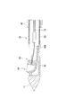
- the operation wire 21 connected to the slider 52 is retracted with respect to the needle tube 10, and the sampling member 13 moves the pin 16 toward the proximal end about the rotation shaft 15 as shown in FIG. It rotates as follows.
- the cup portion 14 moves from the side hole 12 to the outside of the needle tube 10, and a part of the pancreas Pc is cut off by the peripheral edge 14A and accommodated in the accommodating space of the cup portion 14.
- the operator may repeat advancing and retreating of the slider 52 several times as necessary, or combining a retracting operation of the needle tube 10 itself to cut off a part of the pancreas Pc.
- the cup portion 14 enters the needle tube 10 from the side hole 12 again, and the separated tissue piece is accommodated in the needle tube 10.
- the operator retracts the needle tube 10 and removes it from the pancreas Pc, and houses the needle tube 10 in the sheath 40. Thereafter, the biopsy needle 1 is removed from the endoscope, and the tissue piece in the cup portion 14 is collected.
- the sampling member 13 is attached to the needle tube 10 so that the opening of the cup portion 14 faces the side hole 12 of the needle tube 10, the cup portion 14 formed in a cutting edge shape.
- the peripheral edge 14 ⁇ / b> A comes out of the needle tube 10
- the cup portion 14 protrudes out of the needle tube 10 by retracting the slider 52 and pulling the operation wire 21 to the proximal end side. Since the operation wire 21 is excellent in tensile resistance, it is possible to suitably transmit the force by traction to the sampling member. As a result, the tissue can be collected by suitably moving the cup portion 14 out of the needle tube 10 against the tissue existing around the needle tube 10.
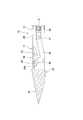
- FIG. 4 is a cross-sectional view showing the puncture portion of the biopsy needle 61 and its periphery.
- the needle tube 62 of the biopsy needle 61 is formed by a hollow metal member only around the puncture portion 11 and the side hole 12, and a coil 63 is connected to the proximal end side.
- An outer blade 64 for assisting collection of a tissue piece is attached to the distal end of the sheath 40.
- the outer blade 64 is made of a material such as metal and is formed in a bowl shape or a half pipe shape having substantially the same diameter as the sheath 40.
- a sharp cutting edge portion 64 ⁇ / b> A is formed at the tip of the outer blade 64.
- the position of the cutting edge part 64A is substantially the same as the position of the opening of the side hole 12 and the cup part 14.
- FIG. 5 An operation when the biopsy needle 61 configured as described above is used will be described.
- the operation until the operation wire 21 is pulled and the cup portion 14 is moved out of the needle tube 62 as shown in FIG. 5 is the same as that in the first embodiment.
- the operator grasps the proximal end portion of the sheath 40 and advances the sheath 40 relative to the operation portion main body 51, or retracts the needle tube 62 relative to the sheath 40.
- the outer blade 64 advances toward the cup portion 14, and the cutting blade portion 64 ⁇ / b> A cuts the target tissue Ts from the side opposite to the peripheral edge 14 ⁇ / b> A of the cup portion 14.
- the target tissue Ts cut by the peripheral edge 14A and the outer blade 64 is accommodated in the cup portion 14 as a tissue piece.
- the biopsy needle 61 of the present embodiment can suitably collect tissue by an easy operation. Further, since the outer blade 64 is provided on the sheath 40, even when the tissue cannot be sufficiently cut only by the cup portion, the cutting can be assisted with the outer blade to reliably collect the tissue.
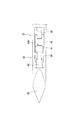
- FIG. 7 is a cross-sectional view showing the puncture portion of the biopsy needle 71 and its periphery.
- a cup portion 14 is formed at the first end 72 ⁇ / b> A in the longitudinal direction of the collection member 72, as with the collection member 13.
- the second end portion 72B opposite to the first end portion 72A is provided with a protruding portion 73 formed in a rod shape or a plate shape.
- the sampling member 72 is supported by the needle tube 62 at the center in the longitudinal direction by the rotation shaft 15.
- a second side hole 74 communicating with the inner cavity is formed on the proximal end side with respect to the rotation shaft 15, and when the sampling member 72 rotates about the rotation shaft 15, the second side A protruding portion 73 protrudes from the hole 74.
- the cup portion 14 protrudes from the side hole 12 by the same operation as in the first embodiment, as shown in FIG.
- the protruding portion 73 provided at the second end portion 72 ⁇ / b> B also protrudes out of the needle tube 62 from the second side hole 74.
- the protruding portion 73 that protrudes presses the surrounding target tissue Ts and receives a reaction force from the target tissue Ts. Since this reaction force works to press the cup portion 14 against the target tissue Ts, the tissue collection by the cup portion 14 is stably performed.
- the biopsy needle 71 of the present embodiment can suitably collect tissue by an easy operation.
- the cup part 14 is pressed suitably on the object structure
- the shape of the protruding portion is not limited to the above-described rod shape or plate shape.
- a second cup portion 75 that functions as a protruding portion may be formed at the second end portion 72B.
- the other cup part (second cup part) functions as a protruding part with respect to one cup part (first cup part) (that is, the cup part 14 (first cup part) It functions as a protruding portion with respect to the two cup portions 75.) Therefore, the tissue can be suitably collected with the two cup portions.
- FIG. 10 is a plan view showing the puncture portion of the biopsy needle 81 and its periphery
- FIG. 11 is a side view showing the same part in a partial cross section.
- the puncture portion 83 of the needle tube 82 is formed sharply by cutting off the outer peripheral surface of the tip obliquely with respect to the central axis at four equally spaced locations in the circumferential direction.
- the sampling member 84 is attached to the needle tube 82 such that the first end portion 84A provided with the cup portion 14 is located on the proximal end side.
- a link pin 85 is provided at the second end portion 84 ⁇ / b> B of the sampling member 84, and a front end portion of a plate-like or rod-like link 86 is attached so as to be rotatable around the link pin 85.
- a connecting member 88 having a link shaft 87 is attached to the distal end of the operation wire 21, and the rear end portion of the link 86 is attached to be rotatable about the link shaft 87.
- the needle tube 82 is provided with a second side hole 89 that communicates with the inner cavity to prevent interference with the link 86.
- a plate-shaped cutting portion 90 is provided between the puncture portion 83 and the sampling member 84, and the cup portion 14 of the sampling member 84 that rotates about the rotation shaft 15 can contact the cutting portion 90. is there.
- the link 86 moves to the proximal side while the second end 84B of the sampling member 84 is moved to the proximal side as shown in FIG. Move to.
- the sampling member 84 rotates about the rotation shaft 15, and the cup portion 14 protrudes out of the needle tube 82 while moving from the proximal end side toward the distal end side, thereby separating the target tissue.
- the peripheral edge 14A of the cup portion 14 is pressed against the cutting portion 90, and the target tissue is cut by the peripheral edge 14A. A part of the cut target tissue is accommodated in the cup portion 14 as a tissue piece.
- the biopsy needle 81 of the present embodiment can suitably collect tissue by an easy operation. Further, since the collection member 84 and the operation wire 21 are connected via the link 86, the rotation range of the collection member can be increased to, for example, about 150 degrees, and the tissue can be more easily separated. Become.
- the cup portion 14 rotates toward the distal end side
- the cup portion may be configured to rotate toward the proximal end side.
- the direction of the opening of the cup portion may be reversed from the direction shown in FIG. 10, and the operation wire 21 may be operated so as to advance from the fully pulled state.
- the structure in which the cup portion is rotated toward the distal end side can perform tissue sampling with a larger force, preferable.
- the cutting part is not essential.
- tissue by fully rotating a collection member, without providing a cutting part may be sufficient.
- the cutting ability may be improved by sufficiently rotating the sampling member and moving the peripheral edge of the cup portion once protruding out of the needle tube into the needle tube again.
- the sampling member does not necessarily have to be attached to the needle tube via the rotation shaft.
- 13 and 14 show a biopsy needle 95 of such a modification.
- the second end portion 96B of the sampling member 96 is formed in a plate shape, and is fixed to the inner surface of the needle tube 62 by welding, brazing, or the like without using a rotating shaft.
- the operation wire 21 is connected to the proximal end side of the cup portion 14.
- the present invention can be used for an endoscopic treatment tool intended for tissue collection.
Landscapes
- Health & Medical Sciences (AREA)
- Life Sciences & Earth Sciences (AREA)
- Surgery (AREA)
- Biomedical Technology (AREA)
- General Health & Medical Sciences (AREA)
- Heart & Thoracic Surgery (AREA)
- Medical Informatics (AREA)
- Molecular Biology (AREA)
- Pathology (AREA)
- Animal Behavior & Ethology (AREA)
- Engineering & Computer Science (AREA)
- Public Health (AREA)
- Veterinary Medicine (AREA)
- Nuclear Medicine, Radiotherapy & Molecular Imaging (AREA)
- Radiology & Medical Imaging (AREA)
- Surgical Instruments (AREA)
- Endoscopes (AREA)
Abstract
内視鏡用処置具は、穿刺部と、前記穿刺部の外周面に設けられて内腔と連通する側孔とを先端部に有し、可撓性を有して長尺に形成された針管と、前記内腔内に収容され、前記針管の径方向外側に向かって開口するカップ部を有する採取部材と、前記採取部材に接続され、前記針管内に進退可能に挿通された操作部材と、を備え、前記操作部材を前記針管に対して移動させると、前記カップ部が前記側孔から突出する。
Description
本発明は、内視鏡用処置具、より詳しくは、組織に穿刺して生検用の組織を採取するための内視鏡用処置具に関する。
本願は、2012年08月13日に、米国に仮出願された米国特許出願第61/682,579号に基づき優先権を主張し、その内容をここに援用する。
本願は、2012年08月13日に、米国に仮出願された米国特許出願第61/682,579号に基づき優先権を主張し、その内容をここに援用する。
従来、内視鏡用処置具の一つとして、組織に穿刺してその一部を生検用に採取するための処置具が知られている。このような内視鏡用処置具は、生検針あるいは生検具などとも呼ばれる。
例えば、特許文献1には、カップを備えた生検具が記載されている。カップは体内に挿入される長尺の挿入部の先端部に備えられ、組織採取部として機能する。カップの基端側には、関節を備えた湾曲式の方向調節機構が設けられている。
また、特許文献2には、鉗子カップを備えた生検具が記載されている。鉗子カップの先端には針状部が形成され、開閉可能である。鉗子カップの開閉は、操作ワイヤの進退によって行われる。
例えば、特許文献1には、カップを備えた生検具が記載されている。カップは体内に挿入される長尺の挿入部の先端部に備えられ、組織採取部として機能する。カップの基端側には、関節を備えた湾曲式の方向調節機構が設けられている。
また、特許文献2には、鉗子カップを備えた生検具が記載されている。鉗子カップの先端には針状部が形成され、開閉可能である。鉗子カップの開閉は、操作ワイヤの進退によって行われる。
しかしながら、このような従来の生検具には以下のような問題がある。
特許文献1に記載の生検具は、柔らかい組織内で組織を採取することはできる。しかしながら、比較的硬い組織を採取する場合、方向調節機構を備えているため、カップの先端を尖らせても、穿刺しようとすると関節が曲がってしまい、組織への穿刺が容易でないという問題がある。
また、特許文献2に記載の生検具は、比較的硬い組織にも穿刺可能であるものの、組織を採取するためにはまず組織内で鉗子カップを開く必要がある。鉗子カップを開く操作は、操作ワイヤの前進で行われるが、操作ワイヤは耐圧縮性に劣るため、前進による力量伝達が良好でなく、鉗子カップに大きな力量を発生させることができない。したがって、穿刺されて周囲に多量の組織が存在する状態では、カップが開きにくく、手技が煩雑となる場合があるという問題がある。
特許文献1に記載の生検具は、柔らかい組織内で組織を採取することはできる。しかしながら、比較的硬い組織を採取する場合、方向調節機構を備えているため、カップの先端を尖らせても、穿刺しようとすると関節が曲がってしまい、組織への穿刺が容易でないという問題がある。
また、特許文献2に記載の生検具は、比較的硬い組織にも穿刺可能であるものの、組織を採取するためにはまず組織内で鉗子カップを開く必要がある。鉗子カップを開く操作は、操作ワイヤの前進で行われるが、操作ワイヤは耐圧縮性に劣るため、前進による力量伝達が良好でなく、鉗子カップに大きな力量を発生させることができない。したがって、穿刺されて周囲に多量の組織が存在する状態では、カップが開きにくく、手技が煩雑となる場合があるという問題がある。
本発明は、上記のような問題に鑑みてなされたものであり、組織採取の前に組織内でカップ部を針管から大きく突出させる必要がなく、容易な操作で好適に組織の採取を行うことができる内視鏡用処置具の提供を目的とする。
上記の課題を解決するために、本発明の第1の態様に係る内視鏡用処置具は、穿刺部と、前記穿刺部の外周面に設けられて内腔と連通する側孔とを先端部に有し、可撓性を有して長尺に形成された針管と、前記内腔内に収容され、前記針管の径方向外側に向かって開口するカップ部を有する採取部材と、前記採取部材に接続され、前記針管内に進退可能に挿通された操作部材と、を備え、前記操作部材を前記針管に対して移動させると、前記カップ部が前記側孔から突出する。
本発明の第2の態様によれば、上記第1の態様において、前記採取部材は、回動軸を介して前記針管に取り付けられ、前記回動軸を中心にして回動可能であってもよい。
本発明の第3の態様によれば、上記第1の態様において、前記針管が進退可能に挿通されるシースと、前記シースの先端部に設けられ、前記採取部材が採取した組織を切断する外刃と、をさらに備えていてもよい。
本発明の第4の態様によれば、上記第2の態様において、前記採取部材は、前記採取部材の長手方向における第一の端部に前記カップ部を有し、前記長手方向における中間部が前記回動軸に支持され、前記操作部材を前記針管に対して後退させると、前記採取部材の前記長手方向における第二の端部が、前記針管に形成された第二側孔から突出していてもよい。回動軸は、採取部材の長手方向において、カップ部と採取部材の基端側との間に位置していればよい。
本発明の第5の態様によれば、上記第4の態様において、前記採取部材の前記第二の端部に設けられ、前記針管の径方向外側に向かって開口する第二カップ部をさらに備えていてもよい。
本発明の第6の態様によれば、上記第2の態様において、前記採取部材と前記操作部材とを連結するリンクをさらに備えていてもよい。
本発明の第7の態様によれば、上記第6の態様において、前記針管に設けられ、回動した前記カップ部が接触する切断部をさらに備えていてもよい。
上記本発明の各態様によれば、組織採取の前に組織内でカップ部を針管から大きく突出させる必要がなく、容易な操作で好適に組織の採取を行うことができる内視鏡用処置具を提供できる。
本発明の第一実施形態について、図1から図3を参照して説明する。
図1は、本実施形態の内視鏡用処置具である生検針1の全体構成を示す図である。生検針1は、可撓性を有する長尺の針管10と、針管10が進退可能に挿通されたシース40と、針管10の基端部に取り付けられた操作部50とを備えている。
図1は、本実施形態の内視鏡用処置具である生検針1の全体構成を示す図である。生検針1は、可撓性を有する長尺の針管10と、針管10が進退可能に挿通されたシース40と、針管10の基端部に取り付けられた操作部50とを備えている。
針管10は、ステンレス等の金属で内腔を有する中空状に形成されているが、外径が例えば0.5~2ミリメートル(mm)程度と細いため、可撓性を有している。針管10の先端部は円錐状に形成されている。円錐状の先端部は、生検対象の組織に刺入される鋭利な穿刺部11である。
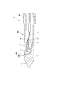
図2は、針管10の先端部およびその周辺の断面図である。針管10の外周面には、内腔に連通する側孔12が設けられている。針管10の内腔には、組織を採取するための採取部材13が配置されている。採取部材13の第一の端部13Aには、採取された組織が収容される収容空間を有するカップ部14が設けられている。収容空間の開口となるカップ部14の周縁14Aは、鋭利な切刃状であり、組織を容易に切離することができる。
図2に示すように、採取部材13のうち、第一の端部13Aと反対側に位置する第二の端部13Bは、針管10を径方向に貫通するように取り付けられた回動軸15に支持されており、回動軸15を中心に回動可能である。採取部材13は、カップ部14が設けられた第一の端部13Aが穿刺部11側にあり、かつカップ部14の開口が針管10の径方向外側かつ側孔12側に向くように取り付けられている。
採取部材13において、カップ部14と回動軸15との中間の部位には、採取部材13を操作するための操作ワイヤ(操作部材)21が接続されている。本実施形態では、操作ワイヤ21は、採取部材13に設けられたピン16に係止されて接続されているが、接続態様はこれに限定されず、例えば溶接等の他の方法で接続されてもよい。操作ワイヤ21は、針管10の内腔を通って操作部50まで延びており、針管10に対して進退可能である。
シース40としては、可撓性を有し、針管10を進退可能に挿通できればよく、公知のシースを適宜選択して使用できる。材質についても特に制限はなく、例えば樹脂やコイル等の公知の各種材料を使用することができる。
操作部50は、図1に示すように、針管10の基端部に固定された操作部本体51と、操作部本体51の長手方向に摺動可能に取り付けられたスライダ52とを備えており、その基本構成は公知である。針管10内を通って延びた操作ワイヤ21の基端部は、操作部本体51の内部空間に突出し、スライダ52に固定されている。したがって、スライダ52を操作部本体51に対して摺動させることで、操作ワイヤ21を針管10に対して進退させることができる。操作部本体51をシース40に対して相対移動させることによって、針管10をシース40に対して進退させ、シース40の先端からの針管10の突出量を調節することができる。
上記のように構成された本実施形態の生検針1の使用時の動作について、膵臓を生検対象の組織(以下、単に「対象組織」と称する。)とする場合を例に挙げて説明する。
術者は、まず図示しない内視鏡を患者の体内に導入し、膵臓の付近まで内視鏡の先端部を移動させる。次に、針管10をシース40内に収容した状態で、生検針1を穿刺部11側から内視鏡の鉗子チャンネルに挿入し、鉗子チャンネルの先端開口からシース40の先端部を突出させる。使用する内視鏡は、対象組織の種類や位置等に応じて、光学内視鏡や超音波内視鏡など、公知の各種の内視鏡を適宜選択してよい。
術者は、内視鏡の画像で膵臓および膵臓のうちの組織片を採取する部位を確認しながら、操作部本体51を操作して、穿刺部11をシース40から突出させ、さらに、穿刺部11を膵臓に刺入する。
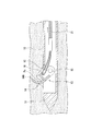
穿刺部11が目標の位置に達したら、術者はスライダ52を牽引する。これにより、スライダ52に接続された操作ワイヤ21が針管10に対して後退し、採取部材13は、図3に示すように、回動軸15を中心として、ピン16が基端側に移動するように回動する。その結果、カップ部14が側孔12から針管10の外に移動し、周縁14Aにより膵臓Pcの一部が切り取られてカップ部14の収容空間に収容される。組織が硬い等の場合、術者は必要に応じてスライダ52の進退を数回繰り返したり、針管10自体の後退操作を組み合わせたりして、膵臓Pcの一部を切離してもよい。
上記操作のあと、術者がスライダ52を前進させると、カップ部14は側孔12から再び針管10内に進入し、切離された組織片も針管10内に収容される。術者は、針管10を後退させて膵臓Pcから抜去するとともに、シース40内に針管10を収容する。その後、生検針1を内視鏡から抜去して、カップ部14内の組織片を回収する。
本実施形態の生検針1によれば、カップ部14の開口が針管10の側孔12に向くように採取部材13が針管10に取り付けられているので、切刃状に形成されたカップ部14の周縁14Aが針管10外に出るとすぐに対象組織と接触し、対象組織を切り進める。したがって、組織採取の前に組織内でカップ部を針管から大きく突出させる必要がなく、組織採取のための操作が容易である。
また、カップ部14は、スライダ52を後退させて操作ワイヤ21を基端側に牽引することにより針管10外に突出する。操作ワイヤ21は引張耐性に優れるため、牽引による力量を好適に採取部材に伝達することができる。その結果、針管10の周囲に存在する組織に抗して好適にカップ部14を針管10外に移動させて組織採取を行うことができる。
次に、本発明の第二実施形態について、図4から図6を参照して説明する。本実施形態の生検針61と上述の第一実施形態における生検針1との異なるところは、外刃をさらに備える点である。以降の説明において、すでに説明した構成と共通する構成については、同一の符号を付して重複する説明を省略する。
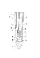
図4は、生検針61の穿刺部およびその周辺を示す断面図である。生検針61の針管62は、穿刺部11および側孔12の周辺だけが中空の金属部材で形成され、基端側にコイル63が接続されて構成されている。シース40の先端には、組織片採取を補助するための外刃64が取り付けられている。
外刃64は金属等の材質で、シース40と略同径の樋状またはハーフパイプ状に形成されている。外刃64の先端には鋭利な切刃部64Aが形成されている。針管62の周方向において、切刃部64Aの位置は側孔12およびカップ部14の開口の位置と略同一である。
上記のように構成された生検針61の使用時の動作について説明する。操作ワイヤ21を牽引して、図5に示すようにカップ部14を針管62の外に移動させるまでの操作は第一実施形態と同一である。操作ワイヤ21の牽引後、術者はシース40の基端部を把持して操作部本体51に対してシース40を前進させる、あるいは針管62をシース40に対して後退させる。すると図6に示すように、外刃64がカップ部14に向かって前進し、切刃部64Aがカップ部14の周縁14Aとは反対側から対象組織Tsを切断する。周縁14Aと外刃64とにより切断された対象組織Tsは、組織片としてカップ部14内に収容される。
本実施形態の生検針61によっても、第一実施形態の生検針1と同様に、容易な操作で好適に組織の採取を行うことができる。また、シース40に外刃64が設けられているため、カップ部のみで充分に組織を切断できなかった等の場合でも、外刃により切断を補助して確実に組織を採取することができる。
次に、本発明の第三実施形態について、図7から図9を参照して説明する。本実施形態の生検針71と上述の各実施形態の生検針との異なるところは、採取部材の形状である。
図7は、生検針71の穿刺部およびその周辺を示す断面図である。採取部材72の長手方向における第一の端部72Aには、採取部材13と同様にカップ部14が形成されている。第一の端部72Aと反対側の第二の端部72Bには棒状または板状に形成された突出部73が設けられている。
採取部材72は、長手方向中央部が回動軸15により針管62に支持されている。針管62の外周面において、回動軸15より基端側には、内腔に連通する第二側孔74が形成され、採取部材72が回動軸15を中心に回動すると、第二側孔74から突出部73が突出する。
上記のように形成された生検針71では、術者が操作ワイヤ21を牽引すると、図8に示すように、第一実施形態と同様の動作でカップ部14が側孔12から突出する。このとき、第二の端部72Bに設けられた突出部73も第二側孔74から針管62外に突出する。突出した突出部73は、周囲の対象組織Tsを押圧するとともに、対象組織Tsから反力を受ける。この反力はカップ部14を対象組織Tsに対して押圧するように働くため、カップ部14による組織の採取が安定して行われる。
本実施形態の生検針71によっても、各実施形態の生検針と同様に、容易な操作で好適に組織の採取を行うことができる。また、第二側孔74および突出部73を備えているため、カップ部14が好適に対象組織Tsに押し当てられ、組織の採取を好適に行うことができる。
本実施形態において、突出部の形状は上述の棒状や板状に限定されない。例えば図9に示す変形例のように、第二の端部72Bに、突出部として機能する第二カップ部75が形成されてもよい。このような構成では、一方のカップ部(第一カップ部)に対して他方のカップ部(第二カップ部)が突出部として機能する(すなわち、カップ部14(第一カップ部)は、第二カップ部75に対して突出部として機能する。)ため、2つのカップ部で好適に組織の採取を行うことができる。
次に、本発明の第4実施形態について、図10から図12を参照して説明する。本実施形態の生検針81と上述の各実施形態の生検針との異なるところは、採取部材と操作部材との接続方法である。
図10は、生検針81の穿刺部およびその周辺を示す平面図であり、図11は、同部位を一部断面で示す側面図である。生検針81において、針管82の穿刺部83は、先端の外周面を、周方向において等間隔の4か所で、中心軸線に対して斜めに切り落とすことにより鋭利に形成されている。
採取部材84は、カップ部14が設けられた第一の端部84Aが基端側に位置するように針管82に取り付けられている。採取部材84の第二の端部84Bには、リンクピン85が設けられ、板状または棒状のリンク86の前端部がリンクピン85を中心に回動可能に取り付けられている。
図11に示すように、操作ワイヤ21の先端には、リンク軸87を有する連結部材88が取り付けられており、リンク86の後端部がリンク軸87を中心に回動可能に取り付けられている。針管82には、内腔に連通する第二側孔89が設けられ、リンク86との干渉を防いでいる。
穿刺部83と採取部材84との間には、板状の切断部90が設けられており、回動軸15を中心に回動する採取部材84のカップ部14が切断部90に接触可能である。
本実施形態の生検針81では、術者が操作ワイヤ21を牽引すると、図12に示すように、リンク86が基端側に移動しつつ採取部材84の第二の端部84Bを基端側に移動させる。その結果、採取部材84が回動軸15を中心に回動し、カップ部14が基端側から先端側に向かって移動しながら針管82の外に突出し、対象組織を切離する。術者がさらに操作ワイヤ21を牽引すると、カップ部14の周縁14Aが切断部90に押し当てられ、周縁14Aにより対象組織が切断される。切断された対象組織の一部は、組織片としてカップ部14内に収容される。
本実施形態の生検針81によっても、上述の各実施形態の生検針と同様に、容易な操作で好適に組織の採取を行うことができる。また、採取部材84と操作ワイヤ21とがリンク86を介して連結されているので、採取部材の回動範囲を、例えば150度程度とより大きくすることができ、組織の切離がさらに容易になる。
本実施形態では、カップ部14が先端側に向かって回動する例を説明したが、カップ部が基端側に向かって回動するように構成してもよい。この場合は、カップ部の開口の向きを図10に示す向きと逆にし、操作ワイヤ21を牽引しきった状態から前進させるように操作すればよい。ただし、上述のように、操作ワイヤは牽引操作による良好な力量伝達性を有するので、カップ部を先端側に向けて回動させる構造の方が、より大きい力で組織採取を行うことができ、好ましい。
また、本実施形態において切断部は必須ではない。例えば、切断部を設けずに、採取部材を充分回動させることで組織を切断する構成でもよい。このとき、採取部材を充分回動させて、一度針管外に突出したカップ部の周縁を再び針管内に移動させることで切断能力を向上させてもよい。
以上、本発明の各実施形態について説明したが、本発明の技術範囲は上記実施形態に限定されず、本発明の趣旨を逸脱しない範囲において構成要素の組み合わせを変えたり、各構成要素に種々の変更を加えたり、削除したりすることが可能である。
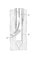
例えば、本発明の内視鏡用処置具において、採取部材は必ずしも回動軸を介して針管に取り付けられなくてもよい。図13および図14には、そのような変形例の生検針95を示している。生検針95では、採取部材96の第二の端部96Bが板状に形成されており、回動軸を介さずに溶接やロウ付け等により針管62の内面に固定されている。操作ワイヤ21はカップ部14の基端側に接続されている。
生検針95では、術者が操作ワイヤ21を牽引すると、図14に示すように、採取部材96のうちカップ部14より基端側の板状の領域が撓むことにより、カップ部14が針管62の外に移動して対象組織Tsを切離する。このような構成でも上述の各実施形態の生検針と同様の効果を奏することができる。
本発明は、組織採取を目的とする内視鏡用処置具に利用可能である。
1,61,71,81,95 生検針
10,62,82 針管
11,83 穿刺部
12 側孔
13,72,84,96 採取部材
13A,72A,84A 第一の端部
13B,72B,84B,96B 第二の端部
14 カップ部(第一カップ部)
15 回動軸
21 操作ワイヤ(操作部材)
40 シース
64 外刃
73 突出部
74,89 第二側孔
75 第二カップ部
86 リンク
88 連結部材
90 切断部
10,62,82 針管
11,83 穿刺部
12 側孔
13,72,84,96 採取部材
13A,72A,84A 第一の端部
13B,72B,84B,96B 第二の端部
14 カップ部(第一カップ部)
15 回動軸
21 操作ワイヤ(操作部材)
40 シース
64 外刃
73 突出部
74,89 第二側孔
75 第二カップ部
86 リンク
88 連結部材
90 切断部
Claims (7)
- 穿刺部と、前記穿刺部の外周面に設けられて内腔と連通する側孔とを先端部に有し、可撓性を有して長尺に形成された針管と、
前記内腔内に収容され、前記針管の径方向外側に向かって開口するカップ部を有する採取部材と、
前記採取部材に接続され、前記針管内に進退可能に挿通された操作部材と、
を備え、
前記操作部材を前記針管に対して移動させると、前記カップ部が前記側孔から突出する内視鏡用処置具。 - 前記採取部材は、回動軸を介して前記針管に取り付けられ、前記回動軸を中心にして回動可能である請求項1に記載の内視鏡用処置具。
- 前記針管が進退可能に挿通されるシースと、
前記シースの先端部に設けられ、前記採取部材が採取した組織を切断する外刃と、をさらに備える請求項1に記載の内視鏡用処置具。 - 前記採取部材は、前記採取部材の長手方向における第一の端部に前記カップ部を有し、前記長手方向における中間部が前記回動軸に支持され、
前記操作部材を前記針管に対して後退させると、前記採取部材の前記長手方向における第二の端部が、前記針管に形成された第二側孔から突出する請求項2に記載の内視鏡用処置具。 - 前記採取部材の前記第二の端部に設けられ、前記針管の径方向外側に向かって開口する第二カップ部をさらに備える請求項4に記載の内視鏡用処置具。
- 前記採取部材と前記操作部材とを連結するリンクをさらに備える請求項2に記載の内視鏡用処置具。
- 前記針管に設けられ、回動した前記カップ部が接触する切断部をさらに備える請求項6に記載の内視鏡用処置具。
Priority Applications (4)
| Application Number | Priority Date | Filing Date | Title |
|---|---|---|---|
| CN201380021878.7A CN104254284B (zh) | 2012-08-13 | 2013-07-24 | 内窥镜用处理器具 |
| JP2014501115A JP5591416B2 (ja) | 2012-08-13 | 2013-07-24 | 内視鏡用処置具 |
| EP13879485.4A EP2883503B1 (en) | 2012-08-13 | 2013-07-24 | Treatment device for endoscope |
| US14/523,231 US9237884B2 (en) | 2012-08-13 | 2014-10-24 | Treatment device for endoscope |
Applications Claiming Priority (2)
| Application Number | Priority Date | Filing Date | Title |
|---|---|---|---|
| US201261682579P | 2012-08-13 | 2012-08-13 | |
| US61/682,579 | 2012-08-13 |
Related Child Applications (1)
| Application Number | Title | Priority Date | Filing Date |
|---|---|---|---|
| US14/523,231 Continuation US9237884B2 (en) | 2012-08-13 | 2014-10-24 | Treatment device for endoscope |
Publications (1)
| Publication Number | Publication Date |
|---|---|
| WO2014027548A1 true WO2014027548A1 (ja) | 2014-02-20 |
Family
ID=50685544
Family Applications (1)
| Application Number | Title | Priority Date | Filing Date |
|---|---|---|---|
| PCT/JP2013/070048 Ceased WO2014027548A1 (ja) | 2012-08-13 | 2013-07-24 | 内視鏡用処置具 |
Country Status (5)
| Country | Link |
|---|---|
| US (1) | US9237884B2 (ja) |
| EP (1) | EP2883503B1 (ja) |
| JP (1) | JP5591416B2 (ja) |
| CN (1) | CN104254284B (ja) |
| WO (1) | WO2014027548A1 (ja) |
Cited By (5)
| Publication number | Priority date | Publication date | Assignee | Title |
|---|---|---|---|---|
| JP2016174901A (ja) * | 2015-03-19 | 2016-10-06 | 哈爾濱醫科大学 | 消化器内視鏡低侵襲手術用双関節鎌形刀 |
| CN110464420A (zh) * | 2019-08-13 | 2019-11-19 | 郑州大学第一附属医院 | 用于心血管治疗的介入装置 |
| CN113164164A (zh) * | 2018-09-18 | 2021-07-23 | 布莱阿姆青年大学 | 可展开和可折叠的外部切割或夹持机构 |
| CN113616255A (zh) * | 2021-08-26 | 2021-11-09 | 中国医科大学附属盛京医院 | 超声内窥镜用穿刺取样针 |
| JP2024013196A (ja) * | 2022-07-19 | 2024-01-31 | 武漢微新坦医療科技有限公司 | 心筋の湾曲調整切断装置及びシステム |
Families Citing this family (10)
| Publication number | Priority date | Publication date | Assignee | Title |
|---|---|---|---|---|
| EP2767214B1 (en) * | 2012-10-10 | 2017-07-19 | Olympus Corporation | Treatment instrument |
| CN106470617B (zh) * | 2014-05-07 | 2019-11-12 | 波士顿科学国际有限公司 | 超声内镜引导下细针抽吸(eus-fna)封闭针 |
| US9662123B2 (en) * | 2014-07-31 | 2017-05-30 | Amendia, Inc. | Vertical cutter and method of use |
| US20160095584A1 (en) * | 2014-10-01 | 2016-04-07 | Boston Scientific Scimed, Inc. | Endoscopic needle with rotary jaw for lateral acquisition |
| JP6542102B2 (ja) * | 2015-11-09 | 2019-07-10 | 富士フイルム株式会社 | 内視鏡 |
| IT201900010158A1 (it) * | 2019-06-26 | 2020-12-26 | Univ Degli Studi Roma Tre | Bisturi ad attuazione remota per trattamenti endoluminali |
| CN111887905A (zh) * | 2020-07-24 | 2020-11-06 | 梁静萍 | 一种用于挖取活体组织的活检钳 |
| CN114711843B (zh) * | 2021-01-04 | 2025-05-06 | 南微医学科技股份有限公司 | 组织取样机构和活检钳 |
| CN113907803B (zh) * | 2021-09-26 | 2024-07-12 | 延边大学 | 一种胰腺癌早期筛查的体内微创精准取材装置及方法 |
| CN114795300A (zh) * | 2022-04-26 | 2022-07-29 | 山东第一医科大学(山东省医学科学院) | 髌内侧滑膜皱襞解剖瘤体取样装置 |
Citations (7)
| Publication number | Priority date | Publication date | Assignee | Title |
|---|---|---|---|---|
| JPS5463990U (ja) * | 1977-10-15 | 1979-05-07 | ||
| JPS5463989U (ja) * | 1977-10-14 | 1979-05-07 | ||
| JPH01133907U (ja) * | 1988-03-09 | 1989-09-12 | ||
| JPH05237120A (ja) * | 1992-02-27 | 1993-09-17 | Asahi Optical Co Ltd | 内視鏡用生検鉗子 |
| JPH11128234A (ja) | 1997-10-31 | 1999-05-18 | Olympus Optical Co Ltd | 組織採取装置 |
| JP2007289673A (ja) | 2006-04-26 | 2007-11-08 | Olympus Medical Systems Corp | 内視鏡用処置具 |
| JP2011061846A (ja) * | 2010-11-11 | 2011-03-24 | Hitachi Kokusai Electric Inc | 携帯電話端末の消費電力を低減する方法 |
Family Cites Families (9)
| Publication number | Priority date | Publication date | Assignee | Title |
|---|---|---|---|---|
| JP3091274B2 (ja) * | 1991-09-20 | 2000-09-25 | 富士写真光機株式会社 | 処置具挿入可能な側視型電子内視鏡 |
| US5301684A (en) * | 1993-04-27 | 1994-04-12 | International Electronic Technology Corp. | Biopsy needle |
| US6638233B2 (en) * | 1999-08-19 | 2003-10-28 | Fox Hollow Technologies, Inc. | Apparatus and methods for material capture and removal |
| US6447525B2 (en) * | 1999-08-19 | 2002-09-10 | Fox Hollow Technologies, Inc. | Apparatus and methods for removing material from a body lumen |
| JP4388172B2 (ja) * | 1999-08-26 | 2009-12-24 | オリンパス株式会社 | 医療用処置具 |
| US7775989B2 (en) * | 2003-09-03 | 2010-08-17 | Granit Medical Innovations, Llc | Needle biopsy forceps with integral sample ejector |
| US7762960B2 (en) * | 2005-05-13 | 2010-07-27 | Boston Scientific Scimed, Inc. | Biopsy forceps assemblies |
| US20090024144A1 (en) * | 2007-07-18 | 2009-01-22 | Zeiner Mark S | Hybrid endoscopic/laparoscopic device for forming serosa to serosa plications in a gastric cavity |
| CN101785700A (zh) * | 2010-01-04 | 2010-07-28 | 上海祥秀医药科技有限公司 | 一种前列腺手术内窥镜 |
-
2013
- 2013-07-24 CN CN201380021878.7A patent/CN104254284B/zh active Active
- 2013-07-24 EP EP13879485.4A patent/EP2883503B1/en active Active
- 2013-07-24 WO PCT/JP2013/070048 patent/WO2014027548A1/ja not_active Ceased
- 2013-07-24 JP JP2014501115A patent/JP5591416B2/ja active Active
-
2014
- 2014-10-24 US US14/523,231 patent/US9237884B2/en active Active
Patent Citations (7)
| Publication number | Priority date | Publication date | Assignee | Title |
|---|---|---|---|---|
| JPS5463989U (ja) * | 1977-10-14 | 1979-05-07 | ||
| JPS5463990U (ja) * | 1977-10-15 | 1979-05-07 | ||
| JPH01133907U (ja) * | 1988-03-09 | 1989-09-12 | ||
| JPH05237120A (ja) * | 1992-02-27 | 1993-09-17 | Asahi Optical Co Ltd | 内視鏡用生検鉗子 |
| JPH11128234A (ja) | 1997-10-31 | 1999-05-18 | Olympus Optical Co Ltd | 組織採取装置 |
| JP2007289673A (ja) | 2006-04-26 | 2007-11-08 | Olympus Medical Systems Corp | 内視鏡用処置具 |
| JP2011061846A (ja) * | 2010-11-11 | 2011-03-24 | Hitachi Kokusai Electric Inc | 携帯電話端末の消費電力を低減する方法 |
Cited By (11)
| Publication number | Priority date | Publication date | Assignee | Title |
|---|---|---|---|---|
| JP2016174901A (ja) * | 2015-03-19 | 2016-10-06 | 哈爾濱醫科大学 | 消化器内視鏡低侵襲手術用双関節鎌形刀 |
| CN113164164A (zh) * | 2018-09-18 | 2021-07-23 | 布莱阿姆青年大学 | 可展开和可折叠的外部切割或夹持机构 |
| JP2022500168A (ja) * | 2018-09-18 | 2022-01-04 | ブリガム ヤング ユニバーシティ | 展開可能および折り畳み可能な外部切断または把持機構 |
| JP7281223B2 (ja) | 2018-09-18 | 2023-05-25 | ブリガム ヤング ユニバーシティ | 展開可能および折り畳み可能な外部切断または把持機構 |
| CN113164164B (zh) * | 2018-09-18 | 2023-10-27 | 布莱阿姆青年大学 | 可展开和可折叠的外部切割或夹持机构 |
| US11938643B2 (en) | 2018-09-18 | 2024-03-26 | Brigham Young University | Developable and collapsable external cutting or gripping mechanism |
| CN110464420A (zh) * | 2019-08-13 | 2019-11-19 | 郑州大学第一附属医院 | 用于心血管治疗的介入装置 |
| CN110464420B (zh) * | 2019-08-13 | 2021-04-02 | 郑州大学第一附属医院 | 用于心血管治疗的介入装置 |
| CN113616255A (zh) * | 2021-08-26 | 2021-11-09 | 中国医科大学附属盛京医院 | 超声内窥镜用穿刺取样针 |
| JP2024013196A (ja) * | 2022-07-19 | 2024-01-31 | 武漢微新坦医療科技有限公司 | 心筋の湾曲調整切断装置及びシステム |
| JP7497485B2 (ja) | 2022-07-19 | 2024-06-10 | 武漢微新坦医療科技有限公司 | 心筋の湾曲調整切断装置及びシステム |
Also Published As
| Publication number | Publication date |
|---|---|
| CN104254284A (zh) | 2014-12-31 |
| EP2883503A1 (en) | 2015-06-17 |
| US20150105692A1 (en) | 2015-04-16 |
| CN104254284B (zh) | 2016-06-29 |
| US9237884B2 (en) | 2016-01-19 |
| EP2883503A4 (en) | 2016-04-13 |
| JPWO2014027548A1 (ja) | 2016-07-25 |
| EP2883503B1 (en) | 2019-04-17 |
| JP5591416B2 (ja) | 2014-09-17 |
Similar Documents
| Publication | Publication Date | Title |
|---|---|---|
| JP5591416B2 (ja) | 内視鏡用処置具 | |
| JP4616301B2 (ja) | 内視鏡用処置具 | |
| US7491212B2 (en) | Transmitting an actuating force along a curved instrument | |
| JP7419067B2 (ja) | 生検装置 | |
| JP5025840B2 (ja) | 医療器具 | |
| CN102196775B (zh) | 活检组织提取处理器具 | |
| JP5997297B2 (ja) | 組織採取装置 | |
| JP6097826B2 (ja) | 組織採取装置 | |
| JP2011519671A (ja) | バイオプシー器具 | |
| WO2016136080A1 (ja) | 内視鏡用穿刺針 | |
| JP6430697B2 (ja) | 内視鏡用の穿刺針 | |
| EP2745764B1 (en) | Treatment instrument for endoscope | |
| US20160081675A1 (en) | Helical driven rotating tissue collection | |
| WO2018220850A1 (ja) | 内視鏡用穿刺針 | |
| WO2014061505A1 (ja) | 内視鏡用処置具 | |
| JP4338712B2 (ja) | 穿刺型細胞診器具 | |
| JP5577000B1 (ja) | 生検具 | |
| JP5927365B1 (ja) | 医療用処置具 | |
| JP4132343B2 (ja) | 生検鉗子 | |
| WO2022244711A1 (ja) | 生検デバイスおよび検体採取方法 | |
| JP7263055B2 (ja) | 生検針 | |
| JP6535132B2 (ja) | 内視鏡用処置具 | |
| EP3174469B1 (en) | Scooper core needle | |
| JP2024151390A (ja) | 生検針 | |
| WO2021083843A1 (en) | Tissue biopsy device |
Legal Events
| Date | Code | Title | Description |
|---|---|---|---|
| ENP | Entry into the national phase |
Ref document number: 2014501115 Country of ref document: JP Kind code of ref document: A |
|
| 121 | Ep: the epo has been informed by wipo that ep was designated in this application |
Ref document number: 13879485 Country of ref document: EP Kind code of ref document: A1 |
|
| NENP | Non-entry into the national phase |
Ref country code: DE |
|
| WWE | Wipo information: entry into national phase |
Ref document number: 2013879485 Country of ref document: EP |