WO2014030512A1 - 打抜加工による鉄損特性の劣化が小さい無方向性電磁鋼板 - Google Patents
打抜加工による鉄損特性の劣化が小さい無方向性電磁鋼板 Download PDFInfo
- Publication number
- WO2014030512A1 WO2014030512A1 PCT/JP2013/070836 JP2013070836W WO2014030512A1 WO 2014030512 A1 WO2014030512 A1 WO 2014030512A1 JP 2013070836 W JP2013070836 W JP 2013070836W WO 2014030512 A1 WO2014030512 A1 WO 2014030512A1
- Authority
- WO
- WIPO (PCT)
- Prior art keywords
- mass
- iron loss
- steel sheet
- less
- punching
- Prior art date
- Legal status (The legal status is an assumption and is not a legal conclusion. Google has not performed a legal analysis and makes no representation as to the accuracy of the status listed.)
- Ceased
Links
Images


Classifications
-
- C—CHEMISTRY; METALLURGY
- C22—METALLURGY; FERROUS OR NON-FERROUS ALLOYS; TREATMENT OF ALLOYS OR NON-FERROUS METALS
- C22C—ALLOYS
- C22C38/00—Ferrous alloys, e.g. steel alloys
- C22C38/02—Ferrous alloys, e.g. steel alloys containing silicon
-
- C—CHEMISTRY; METALLURGY
- C22—METALLURGY; FERROUS OR NON-FERROUS ALLOYS; TREATMENT OF ALLOYS OR NON-FERROUS METALS
- C22C—ALLOYS
- C22C38/00—Ferrous alloys, e.g. steel alloys
- C22C38/60—Ferrous alloys, e.g. steel alloys containing lead, selenium, tellurium, or antimony, or more than 0.04% by weight of sulfur
-
- C—CHEMISTRY; METALLURGY
- C21—METALLURGY OF IRON
- C21D—MODIFYING THE PHYSICAL STRUCTURE OF FERROUS METALS; GENERAL DEVICES FOR HEAT TREATMENT OF FERROUS OR NON-FERROUS METALS OR ALLOYS; MAKING METAL MALLEABLE, e.g. BY DECARBURISATION OR TEMPERING
- C21D8/00—Modifying the physical properties of ferrous metals or ferrous alloys by deformation combined with, or followed by, heat treatment
- C21D8/12—Modifying the physical properties of ferrous metals or ferrous alloys by deformation combined with, or followed by, heat treatment during manufacturing of articles with special electromagnetic properties
- C21D8/1216—Modifying the physical properties of ferrous metals or ferrous alloys by deformation combined with, or followed by, heat treatment during manufacturing of articles with special electromagnetic properties characterised by the working steps
- C21D8/1233—Cold rolling
-
- C—CHEMISTRY; METALLURGY
- C22—METALLURGY; FERROUS OR NON-FERROUS ALLOYS; TREATMENT OF ALLOYS OR NON-FERROUS METALS
- C22C—ALLOYS
- C22C38/00—Ferrous alloys, e.g. steel alloys
- C22C38/001—Ferrous alloys, e.g. steel alloys containing N
-
- C—CHEMISTRY; METALLURGY
- C22—METALLURGY; FERROUS OR NON-FERROUS ALLOYS; TREATMENT OF ALLOYS OR NON-FERROUS METALS
- C22C—ALLOYS
- C22C38/00—Ferrous alloys, e.g. steel alloys
- C22C38/002—Ferrous alloys, e.g. steel alloys containing In, Mg, or other elements not provided for in one single group C22C38/001 - C22C38/60
-
- C—CHEMISTRY; METALLURGY
- C22—METALLURGY; FERROUS OR NON-FERROUS ALLOYS; TREATMENT OF ALLOYS OR NON-FERROUS METALS
- C22C—ALLOYS
- C22C38/00—Ferrous alloys, e.g. steel alloys
- C22C38/004—Very low carbon steels, i.e. having a carbon content of less than 0,01%
-
- C—CHEMISTRY; METALLURGY
- C22—METALLURGY; FERROUS OR NON-FERROUS ALLOYS; TREATMENT OF ALLOYS OR NON-FERROUS METALS
- C22C—ALLOYS
- C22C38/00—Ferrous alloys, e.g. steel alloys
- C22C38/008—Ferrous alloys, e.g. steel alloys containing tin
-
- C—CHEMISTRY; METALLURGY
- C22—METALLURGY; FERROUS OR NON-FERROUS ALLOYS; TREATMENT OF ALLOYS OR NON-FERROUS METALS
- C22C—ALLOYS
- C22C38/00—Ferrous alloys, e.g. steel alloys
- C22C38/04—Ferrous alloys, e.g. steel alloys containing manganese
-
- C—CHEMISTRY; METALLURGY
- C22—METALLURGY; FERROUS OR NON-FERROUS ALLOYS; TREATMENT OF ALLOYS OR NON-FERROUS METALS
- C22C—ALLOYS
- C22C38/00—Ferrous alloys, e.g. steel alloys
- C22C38/06—Ferrous alloys, e.g. steel alloys containing aluminium
-
- H—ELECTRICITY
- H01—ELECTRIC ELEMENTS
- H01F—MAGNETS; INDUCTANCES; TRANSFORMERS; SELECTION OF MATERIALS FOR THEIR MAGNETIC PROPERTIES
- H01F1/00—Magnets or magnetic bodies characterised by the magnetic materials therefor; Selection of materials for their magnetic properties
- H01F1/01—Magnets or magnetic bodies characterised by the magnetic materials therefor; Selection of materials for their magnetic properties of inorganic materials
- H01F1/03—Magnets or magnetic bodies characterised by the magnetic materials therefor; Selection of materials for their magnetic properties of inorganic materials characterised by their coercivity
- H01F1/12—Magnets or magnetic bodies characterised by the magnetic materials therefor; Selection of materials for their magnetic properties of inorganic materials characterised by their coercivity of soft-magnetic materials
- H01F1/14—Magnets or magnetic bodies characterised by the magnetic materials therefor; Selection of materials for their magnetic properties of inorganic materials characterised by their coercivity of soft-magnetic materials metals or alloys
- H01F1/147—Alloys characterised by their composition
- H01F1/14766—Fe-Si based alloys
- H01F1/14775—Fe-Si based alloys in the form of sheets
-
- H—ELECTRICITY
- H01—ELECTRIC ELEMENTS
- H01F—MAGNETS; INDUCTANCES; TRANSFORMERS; SELECTION OF MATERIALS FOR THEIR MAGNETIC PROPERTIES
- H01F1/00—Magnets or magnetic bodies characterised by the magnetic materials therefor; Selection of materials for their magnetic properties
- H01F1/01—Magnets or magnetic bodies characterised by the magnetic materials therefor; Selection of materials for their magnetic properties of inorganic materials
- H01F1/03—Magnets or magnetic bodies characterised by the magnetic materials therefor; Selection of materials for their magnetic properties of inorganic materials characterised by their coercivity
- H01F1/12—Magnets or magnetic bodies characterised by the magnetic materials therefor; Selection of materials for their magnetic properties of inorganic materials characterised by their coercivity of soft-magnetic materials
- H01F1/14—Magnets or magnetic bodies characterised by the magnetic materials therefor; Selection of materials for their magnetic properties of inorganic materials characterised by their coercivity of soft-magnetic materials metals or alloys
- H01F1/147—Alloys characterised by their composition
- H01F1/14766—Fe-Si based alloys
- H01F1/14791—Fe-Si-Al based alloys, e.g. Sendust
-
- H—ELECTRICITY
- H01—ELECTRIC ELEMENTS
- H01F—MAGNETS; INDUCTANCES; TRANSFORMERS; SELECTION OF MATERIALS FOR THEIR MAGNETIC PROPERTIES
- H01F1/00—Magnets or magnetic bodies characterised by the magnetic materials therefor; Selection of materials for their magnetic properties
- H01F1/01—Magnets or magnetic bodies characterised by the magnetic materials therefor; Selection of materials for their magnetic properties of inorganic materials
- H01F1/03—Magnets or magnetic bodies characterised by the magnetic materials therefor; Selection of materials for their magnetic properties of inorganic materials characterised by their coercivity
- H01F1/12—Magnets or magnetic bodies characterised by the magnetic materials therefor; Selection of materials for their magnetic properties of inorganic materials characterised by their coercivity of soft-magnetic materials
- H01F1/14—Magnets or magnetic bodies characterised by the magnetic materials therefor; Selection of materials for their magnetic properties of inorganic materials characterised by their coercivity of soft-magnetic materials metals or alloys
- H01F1/16—Magnets or magnetic bodies characterised by the magnetic materials therefor; Selection of materials for their magnetic properties of inorganic materials characterised by their coercivity of soft-magnetic materials metals or alloys in the form of sheets
-
- C—CHEMISTRY; METALLURGY
- C21—METALLURGY OF IRON
- C21D—MODIFYING THE PHYSICAL STRUCTURE OF FERROUS METALS; GENERAL DEVICES FOR HEAT TREATMENT OF FERROUS OR NON-FERROUS METALS OR ALLOYS; MAKING METAL MALLEABLE, e.g. BY DECARBURISATION OR TEMPERING
- C21D8/00—Modifying the physical properties of ferrous metals or ferrous alloys by deformation combined with, or followed by, heat treatment
- C21D8/12—Modifying the physical properties of ferrous metals or ferrous alloys by deformation combined with, or followed by, heat treatment during manufacturing of articles with special electromagnetic properties
- C21D8/1216—Modifying the physical properties of ferrous metals or ferrous alloys by deformation combined with, or followed by, heat treatment during manufacturing of articles with special electromagnetic properties characterised by the working steps
- C21D8/1222—Hot rolling
-
- C—CHEMISTRY; METALLURGY
- C21—METALLURGY OF IRON
- C21D—MODIFYING THE PHYSICAL STRUCTURE OF FERROUS METALS; GENERAL DEVICES FOR HEAT TREATMENT OF FERROUS OR NON-FERROUS METALS OR ALLOYS; MAKING METAL MALLEABLE, e.g. BY DECARBURISATION OR TEMPERING
- C21D8/00—Modifying the physical properties of ferrous metals or ferrous alloys by deformation combined with, or followed by, heat treatment
- C21D8/12—Modifying the physical properties of ferrous metals or ferrous alloys by deformation combined with, or followed by, heat treatment during manufacturing of articles with special electromagnetic properties
- C21D8/1244—Modifying the physical properties of ferrous metals or ferrous alloys by deformation combined with, or followed by, heat treatment during manufacturing of articles with special electromagnetic properties characterised by the heat treatment
- C21D8/1261—Modifying the physical properties of ferrous metals or ferrous alloys by deformation combined with, or followed by, heat treatment during manufacturing of articles with special electromagnetic properties characterised by the heat treatment following hot rolling
-
- C—CHEMISTRY; METALLURGY
- C21—METALLURGY OF IRON
- C21D—MODIFYING THE PHYSICAL STRUCTURE OF FERROUS METALS; GENERAL DEVICES FOR HEAT TREATMENT OF FERROUS OR NON-FERROUS METALS OR ALLOYS; MAKING METAL MALLEABLE, e.g. BY DECARBURISATION OR TEMPERING
- C21D8/00—Modifying the physical properties of ferrous metals or ferrous alloys by deformation combined with, or followed by, heat treatment
- C21D8/12—Modifying the physical properties of ferrous metals or ferrous alloys by deformation combined with, or followed by, heat treatment during manufacturing of articles with special electromagnetic properties
- C21D8/1244—Modifying the physical properties of ferrous metals or ferrous alloys by deformation combined with, or followed by, heat treatment during manufacturing of articles with special electromagnetic properties characterised by the heat treatment
- C21D8/1272—Final recrystallisation annealing
Definitions
- the present invention relates to a non-oriented electrical steel sheet that not only has excellent iron loss characteristics before punching, but also has low deterioration of iron loss characteristics due to punching.
- Non-oriented electrical steel sheets are disclosed.
- Patent Document 1 contains a large amount of S compared to the conventional non-oriented electrical steel sheet, it is inferior to the magnetic properties of the material steel sheet itself before punching, so The strict requirements for loss characteristics are not fully met. Therefore, development of a non-oriented electrical steel sheet that not only excels in iron loss characteristics before punching but also in iron loss characteristics after punching, that is, deterioration of iron loss characteristics due to punching is small. It is strongly desired.
- the present invention has been made in view of the above-described problems of the prior art, and its purpose is non-directional with excellent iron loss characteristics before punching and small deterioration of iron loss characteristics due to punching. It is to provide an electrical steel sheet.
- the inventors have affected the influence of the composition of the steel sheet and the amount of sag of the steel sheet generated by punching (hereinafter also referred to as “sag amount”) on the iron loss characteristics.
- sag amount the amount of sag of the steel sheet generated by punching
- the size of the sag of the steel sheet generated by punching has a good correlation with the deterioration rate of the iron loss characteristics, and the size of the sag can be increased by adding appropriate amounts of Se and As. It has been found that the iron loss characteristics of the steel sheet can be reduced without degrading, and consequently, the deterioration of the iron loss characteristics due to punching can be suppressed, and the present invention has been developed.
- the present invention provides C: 0.005 mass% or less, Si: 2 to 7 mass%, Mn: 0.03 to 3 mass%, Al: 3 mass% or less, P: 0.2 mass% or less, S: 0.00. 005 mass% or less, N: 0.005 mass% or less, Se: 0.0001 to 0.0005 mass% and As: 0.0005 to 0.005 mass%, with the balance being composed of Fe and inevitable impurities Further, the iron loss W 15/50 at the time of 50 Hz, 1.5T excitation is 3.5 W / kg or less, and the ratio (x / t) of the sagging amount x (mm) and the plate thickness t (mm) at the time of punching the steel sheet ) Is 0.15 or less, the non-oriented electrical steel sheet.
- the non-oriented electrical steel sheet of the present invention is characterized in that the average crystal grain size is 30 to 150 ⁇ m.
- non-oriented electrical steel sheet of the present invention may further include any one or two of Sn: 0.003-0.5 mass% and Sb: 0.003-0.5 mass% in addition to the above component composition. It contains seeds.
- the non-oriented electrical steel sheet has not only excellent iron loss characteristics before punching but also excellent iron loss characteristics after punching, that is, deterioration of iron loss characteristics due to punching is small. Can be provided stably, which can greatly contribute to the improvement of the efficiency of electric devices such as motors using iron cores manufactured by punching.
- test pieces having a length of 180 mm ⁇ width of 30 mm and length of 180 mm ⁇ width of 10 mm were collected by punching with a clearance set to 5%.
- the clearance is a value (%) obtained by dividing the gap between the upper die and the lower die by the plate thickness of the workpiece.
- size (sag amount) of the end face was measured.
- the sagging amount was defined as shown in FIG.
- the iron loss W15 / 50 was measured by the Epstein test.
- the test piece having a width of 10 mm was measured by arranging three test pieces in the width direction so as to have a width of 30 mm.
- two shear portions are included in the test piece having a width of 30 mm, so that the influence of the punching process on the iron loss characteristics can be evaluated. .
- the effect of punching on the iron loss is defined by the following formula: the deterioration rate of the iron loss W 15/50 of the test piece having a width of 10 mm with respect to the iron loss W 15/50 of the test piece having a width of 30 mm ( (Iron loss deterioration rate).
- Iron loss deterioration rate (%) ⁇ (W 15/50 (10 mm width)) ⁇ (W 15/50 (30 mm width)) ⁇ / (W 15/50 (30 mm width)) ⁇ 100
- FIG. 3 shows the relationship between the ratio of the sagging amount x and the plate thickness t (x / t) during punching and the iron loss deterioration rate for the above measurement results. From this figure, it can be seen that the iron loss deterioration rate can be reduced to 20% or less by setting the ratio (x / t) between the sagging amount x and the sheet thickness t to 0.15 or less. This is considered to be because when the ratio (x / t) between the sagging amount and the plate thickness is large, compressive stress remains in the vicinity of the end face generated by the punching process, and the magnetic characteristics deteriorate. From this result, in the present invention, the ratio (x / t) between the sagging amount x and the plate thickness t is set to 0.15 or less.
- a cold-rolled sheet with a thickness of 0.50 mm is obtained by one cold rolling, and then finish annealing at 970 ° C. for 10 seconds. And an insulating coating was applied to obtain a non-oriented electrical steel sheet (product board).
- a test piece having a length of 180 mm and a width of 10 mm was collected by punching with a clearance set to 5%, and the same as in the above ⁇ Experiment 1>. While measuring the sagging amount of the punched end face, the iron loss W 15/50 was measured by the Epstein test. The iron loss of the test piece having a width of 10 mm was measured by arranging three test pieces in the width direction and having a width of 30 mm.
- FIG. 4 shows the effect of Se content on the ratio (x / t) of the sagging amount x and the sheet thickness t and the iron loss W 15/50
- FIG. 5 shows the relationship between the sagging amount x and the sheet thickness t.
- As content on the ratio (x / t) and the iron loss W 15/50 is shown. From these figures, it is understood that the size of the sagging can be reduced by setting Se ⁇ 0.0001 mass% and As ⁇ 0.0005 mass%. This is thought to be because Se and As are segregation elements at the grain boundary and have the effect of weakening the grain boundary strength, so that the shear resistance during punching is reduced and sagging is reduced.
- finish annealing is performed by holding for 10 seconds at various temperatures ranging from 750 to 1100 ° C. Different non-oriented electrical steel sheets (product sheets) were used.
- FIG. 6A shows the influence of the crystal grain size on the ratio (x / t) between the sagging amount x and the plate thickness t. From this figure, it can be seen that by setting the average crystal grain size to 150 ⁇ m or less, the amount of sag during punching can be reduced. This is considered to be because when the crystal grain size becomes small, the existence frequency of the grain boundary becomes high and the shear resistance at the time of the punching process becomes small.
- FIG. 6B shows the effect of the crystal grain size on the iron loss W 15/50 . From this figure, it can be seen that the iron loss W 15/50 deteriorates when the average crystal grain size is 30 ⁇ m or less. This is presumably because the hysteresis loss increases as the crystal grain size decreases. From the above, it can be seen that the average grain size of the non-oriented electrical steel sheet of the present invention is preferably in the range of 30 to 150 ⁇ m.
- C 0.005 mass% or less
- magnetic aging may occur and iron loss may be deteriorated. Therefore, C is set to 0.005 mass% or less.
- Si 2 to 7 mass%
- Si is an element effective in increasing the specific resistance of steel and reducing iron loss, but the effect is small when it is less than 2 mass%. On the other hand, if it exceeds 7 mass%, the steel becomes hard and difficult to manufacture by rolling. Therefore, Si is set in the range of 2 to 7 mass%.
- Mn 0.03 to 3 mass% Mn is an element necessary for improving hot workability. However, if the amount is less than 0.03 mass%, the above effect is not sufficient. On the other hand, addition of more than 3 mass% causes an increase in raw material cost. Therefore, Mn is set to a range of 0.03 to 3 mass%.
- Al 3 mass% or less Al, like Si, is an element effective in increasing the specific resistance of steel and reducing iron loss. However, addition exceeding 3 mass% hardens the steel and makes it difficult to roll and manufacture. Therefore, Al is 3 mass% or less.
- P 0.2 mass% or less
- P is added in order to increase the specific resistance of steel and reduce iron loss.
- the embrittlement of steel becomes significant. Breaks during cold rolling. Therefore, P is limited to 0.2 mass% or less.
- S 0.005 mass% or less
- N 0.005 mass% or less
- Se and As are grain boundary segregation elements, and have an effect of suppressing the occurrence of sagging during punching by weakening the grain boundary strength.
- the said effect is acquired by addition of Se: 0.0001 mass% or more and As: 0.0005 mass% or more.
- Se: 0.0005 mass% and As: 0.005 mass% a large amount of precipitates are formed and the hysteresis loss is increased, so that the iron loss characteristics are deteriorated. Therefore, Se and As are in the range of Se: 0.0001 to 0.0005 mass% and As: 0.0005 to 0.005 mass%.
- the balance other than the essential components is Fe and inevitable impurities.
- any one or two of Sn: 0.003-0.5 mass% and Sb: 0.003-0.5 mass% may be added.
- Sn and Sb are elements having an effect of suppressing the oxidation and nitriding of the steel sheet surface layer and the accompanying generation of surface fine grains and preventing the deterioration of magnetic properties. In order to exhibit such an effect, it is preferable to contain each 0.003 mass% or more. On the other hand, if it exceeds 0.5 mass%, the growth of crystal grains may be hindered, leading to deterioration of magnetic properties. Therefore, Sn and Sb are preferably added in the range of 0.003 to 0.5 mass%, respectively.
- the method for producing a non-oriented electrical steel sheet of the present invention is a method of melting steel having a component composition suitable for the present invention described above in a conventional refining process using a converter, an electric furnace, a vacuum degassing apparatus, etc.
- the steel slab is hot-rolled, hot-rolled sheet annealed as necessary, cold-rolled, finish-annealed, and coated with an insulating coating. It is preferable to consist of a series of steps.
- the said cold rolling may be performed by one cold rolling, and may be performed by the cold rolling of 2 times or more on both sides of intermediate annealing.
- the rolling reduction may be the same as the manufacturing conditions of a normal non-oriented electrical steel sheet.
- the finish annealing is not particularly limited except that the annealing conditions are set so that the average crystal grain size is within the preferred range of the present invention (30 to 150 ⁇ m), and the annealing conditions for ordinary non-oriented electrical steel sheets are not limited. What is necessary is just to carry out according to it.
- the annealing temperature is preferably in the range of 770 to 1050 ° C., and more preferably in the range of 800 to 1020 ° C.
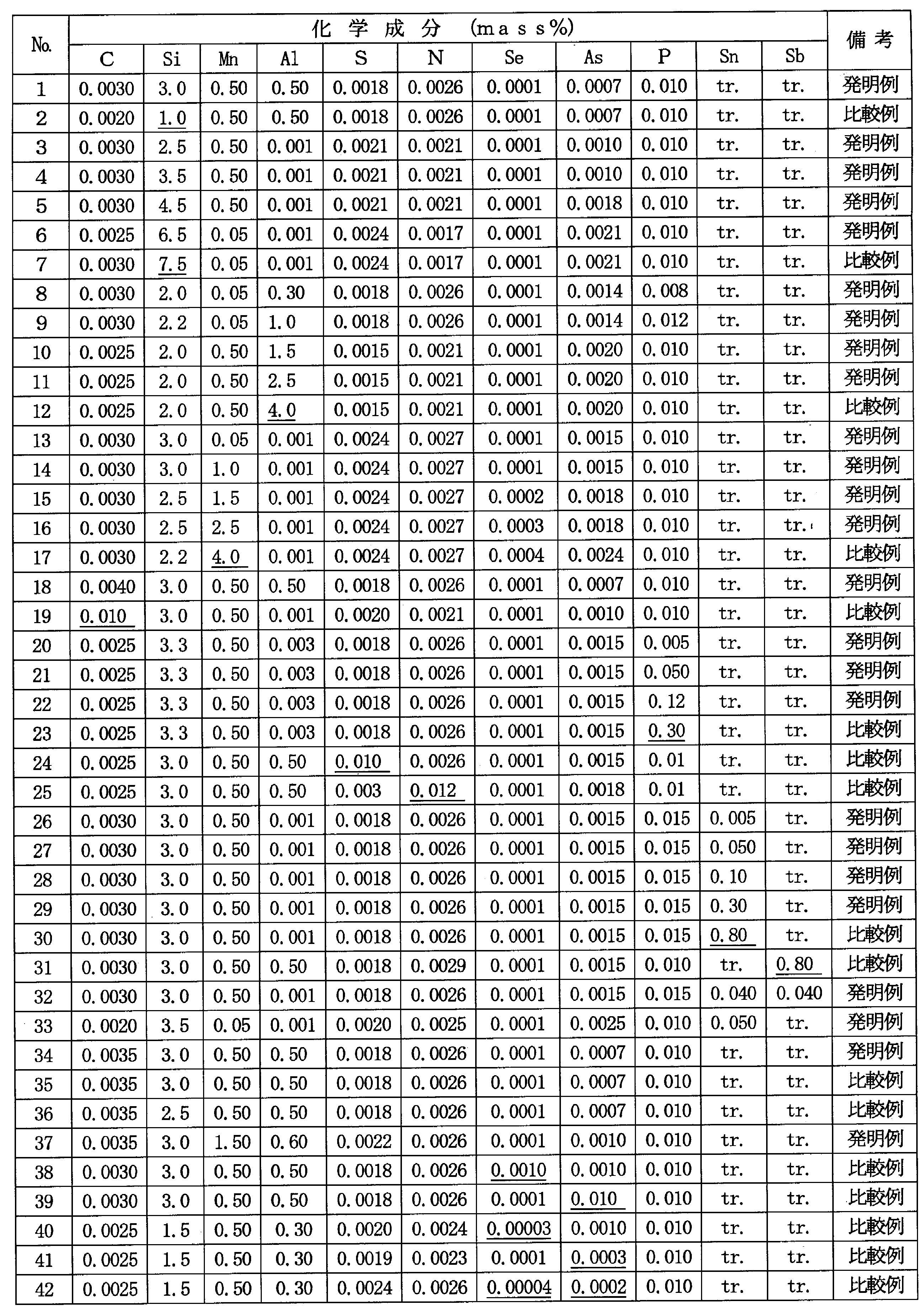
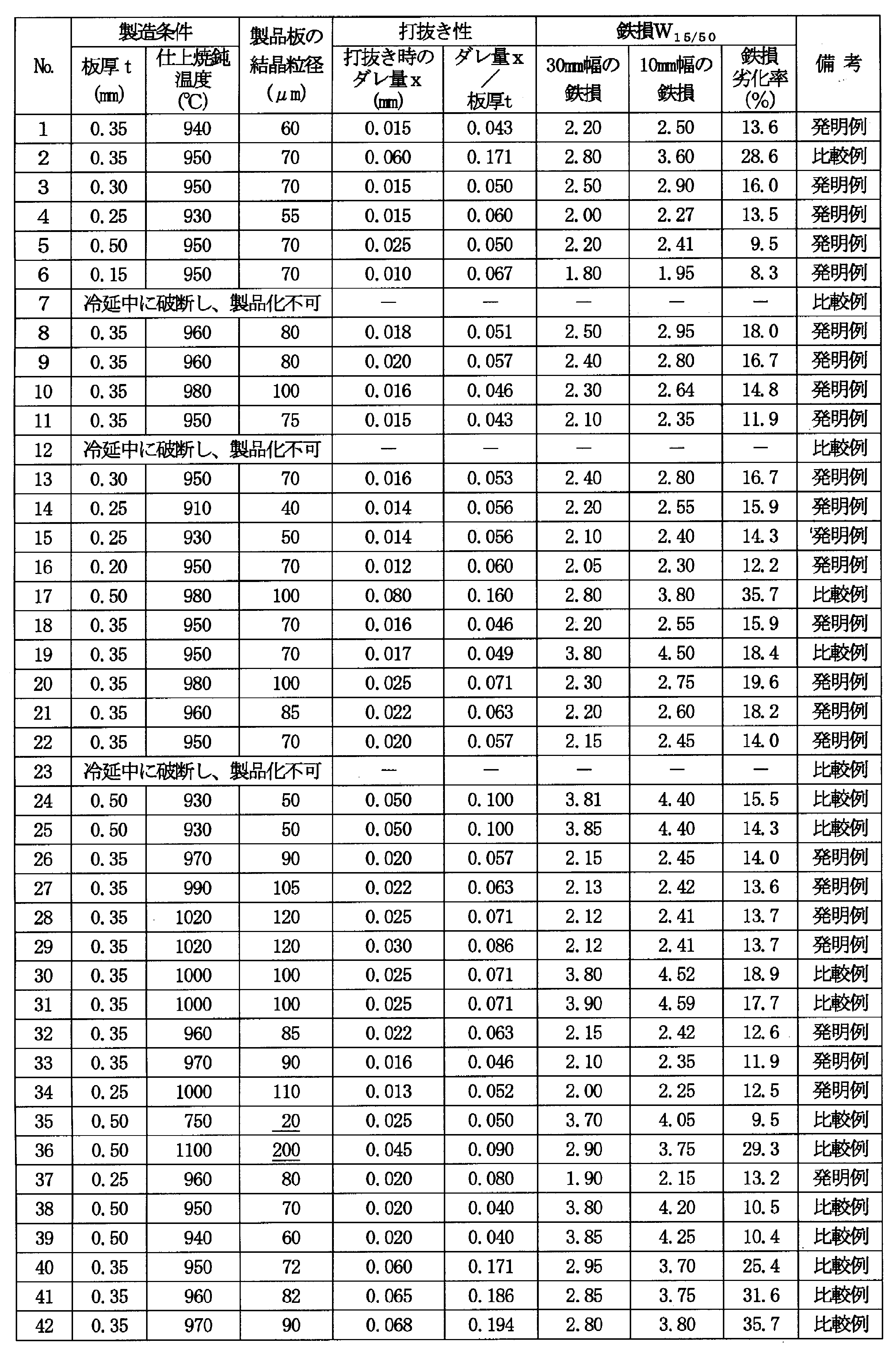
- a steel slab having the various composition shown in Table 1 is reheated at 1100 ° C. for 30 minutes, and then hot-rolled to form a hot-rolled sheet having a thickness of 2.0 mm.
- cold-rolled sheets with various plate thicknesses shown in Table 2 are formed by one cold rolling, and then finish annealing is performed for 10 seconds at various temperatures similarly shown in Table 2, and non-directional.
Landscapes
- Chemical & Material Sciences (AREA)
- Engineering & Computer Science (AREA)
- Organic Chemistry (AREA)
- Mechanical Engineering (AREA)
- Materials Engineering (AREA)
- Metallurgy (AREA)
- Physics & Mathematics (AREA)
- Electromagnetism (AREA)
- Power Engineering (AREA)
- Dispersion Chemistry (AREA)
- Manufacturing & Machinery (AREA)
- Crystallography & Structural Chemistry (AREA)
- Thermal Sciences (AREA)
- Soft Magnetic Materials (AREA)
- Manufacturing Of Steel Electrode Plates (AREA)
Description
<実験1>
まず、打抜加工で発生するダレの大きさ(ダレ量)が、鉄損特性に及ぼす影響について調査するため、C:0.0025mass%、Si:3.0mass%、Al:0.5mass%、Mn:0.5mass%、P:0.01mass%、N:0.0018mass%、S:0.0019mass%、Se:0.0001mass%およびAs:0.0010mass%を含有する鋼スラブを1100℃×30分加熱した後、熱間圧延して板厚2.0mmの熱延板とし、980℃×30秒の熱延板焼鈍を施した後、1回の冷間圧延で板厚0.20~0.50mmの各種板厚を有する冷延板とし、その後、950℃×10秒の仕上焼鈍を施し、絶縁被膜を被成して無方向性電磁鋼板(製品板)とした。なお、上記製品板の圧延方向(L方向)断面における平均結晶粒径を線分法で求めたところ、約80μmであった。
記
鉄損劣化率(%)={(W15/50(10mm幅))-(W15/50(30mm幅))}/(W15/50(30mm幅))×100
次に、発明者らは、上記打抜加工で生じた端面のダレ量を低減する方策として、粒界偏析型で、粒界強度を弱める元素であるSeとAsに着目し、以下の実験を行った。
C:0.0030mass%、Si:2.5mass%、Al:1mass%、Mn:0.5mass%、P:0.01mass%、N:0.0020mass%、S:0.0022mass%を含有し、かつ、Seを0.0001~0.002mass%、Asを0.0001~0.010mass%の範囲で含有する鋼スラブを1100℃×30分加熱した後、熱間圧延して板厚2.0mmの熱延板とし、980℃×30秒の熱延板焼鈍を施した後、1回の冷間圧延で板厚0.50mmの冷延板とし、その後、970℃×10秒の仕上焼鈍を施し、絶縁被膜を被成して無方向性電磁鋼板(製品板)とした。
以上の結果から、本発明では、Seは0.0001~0.0005mass%、Asは0.0005~0.005mass%の範囲で添加することとした。
次に、発明者らは、ダレ量に及ぼす結晶粒径の影響について調査する実験を行った。
C:0.0020mass%、Si:2.5mass%、Al:0.001mass%、Mn:0.5mass%、P:0.01mass%、N:0.0019mass%、S:0.0024mass%、Se:0.0001mass%およびAs:0.0008mass%を含有する鋼スラブを1100℃×30分加熱した後、熱間圧延して板厚2.0mmの熱延板とし、1000℃×30秒の熱延板焼鈍を施し、1回の冷間圧延で板厚0.35mmの冷延板とした後、750~1100℃の範囲の種々の温度で10秒間保持する仕上焼鈍を施し、結晶粒径が異なる無方向性電磁鋼板(製品板)とした。
以上のことから、本発明の無方向性電磁鋼板の平均結晶粒径は、30~150μmの範囲とすることが好ましいことがわかる。
C:0.005mass%以下
Cは、0.005mass%を超えて含有すると、磁気時効を起こして鉄損が劣化するおそれがある。よって、Cは0.005mass%以下とする。
Siは、鋼の固有抵抗を高め、鉄損を低減するのに有効な元素であるが、2mass%未満では上記効果が小さい。一方、7mass%を超えると、鋼が硬質化し、圧延して製造することが困難となる。よって、Siは2~7mass%の範囲とする。
Mnは、熱間加工性を改善するために必要な元素であるが、0.03mass%未満では上記効果が十分ではなく、一方、3mass%を超える添加は、原料コストの上昇を招く。よって、Mnは0.03~3mass%の範囲とする。
Alは、Siと同様、鋼の固有抵抗を高め、鉄損を低減するのに有効な元素である。しかし、3mass%を超える添加は、鋼が硬質化し、圧延して製造することが困難となる。よって、Alは3mass%以下とする。
Pは、本発明では、鋼の固有抵抗を高め、鉄損を低減するために添加するが、0.2mass%を超えて添加すると、鋼の脆化が著しくなり、冷間圧延時に破断を起こすようになる。よって、Pは0.2mass%以下に制限する。
SおよびNは、いずれも不可避的不純物元素であり、0.005mass%を超えて含有すると、磁気特性を劣化させる。よって、SおよびNは、それぞれ0.005mass%以下に制限する。
SeおよびAsは、前述したように、粒界偏析型元素であり、粒界強度を弱めることによって、打抜加工時のダレの発生を抑制する効果がある。上記効果はSe:0.0001mass%以上、As:0.0005mass%以上の添加で得られる。一方、Se:0.0005mass%およびAs:0.005mass%を超える添加は、析出物が多量に形成され、ヒステリシス損が増大するため、鉄損特性が劣化する。よって、SeおよびAsは、Se:0.0001~0.0005mass%、As:0.0005~0.005mass%の範囲とする。
SnおよびSbは、鋼板表層の酸化や窒化、および、それに伴う表層微細粒の生成を抑制し、磁気特性の劣化を防止する作用効果を有する元素である。斯かる効果を発現させるためには、それぞれ0.003mass%以上含有させることが好ましい。一方、0.5mass%を超えると、結晶粒の成長が阻害されて、磁気特性の劣化を招くおそれがある。よって、SnおよびSbは、それぞれ0.003~0.5mass%の範囲で添加するのが好ましい。
本発明の無方向性電磁鋼板の製造方法は、前述した本発明に適合する成分組成を有する鋼を転炉や電気炉、真空脱ガス装置などを用いた常法の精錬プロセスで溶製し、連続鋳造法あるいは造塊-分塊圧延法で鋼スラブとした後、該鋼スラブを熱間圧延し、必要に応じて熱延板焼鈍し、冷間圧延し、仕上焼鈍し、絶縁被膜を被成する一連の工程からなるものであることが好ましい。
上記製造方法において、熱延板焼鈍以前の製造条件については、特に制限はなく、通常公知の条件で製造することができる。
また、上記冷間圧延は、1回の冷間圧延で行ってもよく、中間焼鈍を挟む2回以上の冷間圧延で行ってもよい。また、その圧下率も、通常の無方向性電磁鋼板の製造条件と同様で構わない。
また、上記仕上焼鈍は、平均結晶粒径が本発明の好ましい範囲(30~150μm)となるように焼鈍条件を設定すること以外は特に制限はなく、通常の無方向性電磁鋼板の焼鈍条件に準じて実施すればよい。なお、結晶粒径を上記範囲に制御するには、焼鈍温度は770~1050℃の範囲とするのが好ましく、800~1020℃の範囲とするのがより好ましい。
Claims (3)
- C:0.005mass%以下、Si:2~7mass%、Mn:0.03~3mass%、Al:3mass%以下、P:0.2mass%以下、S:0.005mass%以下、N:0.005mass%以下、Se:0.0001~0.0005mass%およびAs:0.0005~0.005mass%を含有し、残部がFeおよび不可避的不純物からなる成分組成を有し、50Hz、1.5T励磁時の鉄損W15/50が3.5W/kg以下であり、かつ、鋼板打抜き時のダレ量x(mm)と板厚t(mm)との比(x/t)が0.15以下であることを特徴とする無方向性電磁鋼板。
- 平均結晶粒径が30~150μmであることを特徴とする請求項1に記載の無方向性電磁鋼板。
- 上記成分組成に加えてさらに、Sn:0.003~0.5mass%およびSb:0.003~0.5mass%のうちのいずれか1種または2種を含有することを特徴とする請求項1または2に記載の無方向性電磁鋼板。
Priority Applications (5)
| Application Number | Priority Date | Filing Date | Title |
|---|---|---|---|
| IN825DEN2015 IN2015DN00825A (ja) | 2012-08-21 | 2013-08-01 | |
| KR1020157001046A KR101713802B1 (ko) | 2012-08-21 | 2013-08-01 | 펀칭 가공에 의한 철손 특성의 열화가 작은 무방향성 전자 강판 |
| US14/418,351 US9767946B2 (en) | 2012-08-21 | 2013-08-01 | Non-oriented electrical steel sheet being less in deterioration of iron loss property by punching |
| CN201380025093.7A CN104302801B (zh) | 2012-08-21 | 2013-08-01 | 冲裁加工导致的铁损特性劣化较小的无方向性电磁钢板 |
| EP13830303.7A EP2889389B8 (en) | 2012-08-21 | 2013-08-01 | Non-oriented electrical steel sheet being less in deterioration of iron loss property by punching |
Applications Claiming Priority (2)
| Application Number | Priority Date | Filing Date | Title |
|---|---|---|---|
| JP2012182322A JP5533958B2 (ja) | 2012-08-21 | 2012-08-21 | 打抜加工による鉄損劣化の小さい無方向性電磁鋼板 |
| JP2012-182322 | 2012-08-21 |
Publications (1)
| Publication Number | Publication Date |
|---|---|
| WO2014030512A1 true WO2014030512A1 (ja) | 2014-02-27 |
Family
ID=50149822
Family Applications (1)
| Application Number | Title | Priority Date | Filing Date |
|---|---|---|---|
| PCT/JP2013/070836 Ceased WO2014030512A1 (ja) | 2012-08-21 | 2013-08-01 | 打抜加工による鉄損特性の劣化が小さい無方向性電磁鋼板 |
Country Status (7)
| Country | Link |
|---|---|
| US (1) | US9767946B2 (ja) |
| EP (1) | EP2889389B8 (ja) |
| JP (1) | JP5533958B2 (ja) |
| KR (1) | KR101713802B1 (ja) |
| IN (1) | IN2015DN00825A (ja) |
| TW (1) | TWI479032B (ja) |
| WO (1) | WO2014030512A1 (ja) |
Cited By (5)
| Publication number | Priority date | Publication date | Assignee | Title |
|---|---|---|---|---|
| JP2016104902A (ja) * | 2014-11-19 | 2016-06-09 | Jfeスチール株式会社 | 高けい素鋼板 |
| WO2016136095A1 (ja) * | 2015-02-24 | 2016-09-01 | Jfeスチール株式会社 | 無方向性電磁鋼板の製造方法 |
| WO2018221126A1 (ja) * | 2017-05-31 | 2018-12-06 | Jfeスチール株式会社 | 無方向性電磁鋼板とその製造方法 |
| JP2021509154A (ja) * | 2017-12-26 | 2021-03-18 | ポスコPosco | 無方向性電磁鋼板およびその製造方法 |
| US11114227B2 (en) * | 2015-12-28 | 2021-09-07 | Jfe Steel Corporation | Non-oriented electrical steel sheet and method for manufacturing non-oriented electrical steel sheet |
Families Citing this family (13)
| Publication number | Priority date | Publication date | Assignee | Title |
|---|---|---|---|---|
| JP6057082B2 (ja) * | 2013-03-13 | 2017-01-11 | Jfeスチール株式会社 | 磁気特性に優れる無方向性電磁鋼板 |
| JP5995002B2 (ja) | 2013-08-20 | 2016-09-21 | Jfeスチール株式会社 | 高磁束密度無方向性電磁鋼板およびモータ |
| CN107075640A (zh) * | 2014-10-30 | 2017-08-18 | 杰富意钢铁株式会社 | 无取向性电磁钢板和无取向性电磁钢板的制造方法 |
| JP6327181B2 (ja) * | 2015-03-13 | 2018-05-23 | Jfeスチール株式会社 | 高けい素鋼板 |
| KR102003857B1 (ko) * | 2017-10-27 | 2019-10-17 | 주식회사 포스코 | 무방향성 전기강판 및 그 제조방법 |
| CN108857578B (zh) * | 2018-05-07 | 2019-07-05 | 马鞍山钢铁股份有限公司 | 一种磁性能试验板件剪切质量监控方法 |
| JP7028337B2 (ja) * | 2018-10-24 | 2022-03-02 | 日本製鉄株式会社 | 無方向性電磁鋼板とそれを用いた積層コアの製造方法 |
| EP3875612A4 (en) * | 2018-11-02 | 2022-07-06 | Nippon Steel Corporation | NON-ORIENTED ELECTROMAGNETIC STEEL |
| US12148555B2 (en) * | 2018-11-02 | 2024-11-19 | Nippon Steel Corporation | Non-oriented electrical steel sheet |
| KR102175065B1 (ko) | 2018-11-30 | 2020-11-05 | 주식회사 포스코 | 무방향성 전기강판 및 그 제조방법 |
| US11732319B2 (en) | 2018-12-27 | 2023-08-22 | Jfe Steel Corporation | Non-oriented electrical steel sheet |
| KR102278897B1 (ko) * | 2019-12-19 | 2021-07-16 | 주식회사 포스코 | 무방향성 전기강판 및 그 제조방법 |
| CN115398012A (zh) * | 2020-04-02 | 2022-11-25 | 日本制铁株式会社 | 无取向电磁钢板及其制造方法 |
Citations (4)
| Publication number | Priority date | Publication date | Assignee | Title |
|---|---|---|---|---|
| JP2970436B2 (ja) | 1994-11-11 | 1999-11-02 | 住友金属工業株式会社 | フルプロセス無方向性電磁鋼板の製造方法 |
| JP2001131717A (ja) * | 1999-11-05 | 2001-05-15 | Kawasaki Steel Corp | 打ち抜き性に優れた低鉄損無方向性電磁鋼板 |
| JP2001323344A (ja) * | 2000-05-15 | 2001-11-22 | Kawasaki Steel Corp | 加工性およびリサイクル性に優れた無方向性電磁鋼板 |
| JP2007247047A (ja) * | 2006-03-20 | 2007-09-27 | Nippon Steel Corp | 無方向性電磁鋼板 |
Family Cites Families (24)
| Publication number | Priority date | Publication date | Assignee | Title |
|---|---|---|---|---|
| JPS5853694B2 (ja) * | 1980-08-07 | 1983-11-30 | 川崎製鉄株式会社 | 優れた磁気特性を有する面内無方向性高珪素鋼薄帯の製造方法 |
| DE3135438A1 (de) | 1981-09-08 | 1983-03-24 | Robert Bosch Gmbh, 7000 Stuttgart | Vakuumfluegelpumpe |
| JP2540946B2 (ja) * | 1989-06-30 | 1996-10-09 | 日本鋼管株式会社 | 磁気特性に優れた無方向性電磁鋼板およびその製造方法 |
| EP0741191B1 (en) * | 1995-05-02 | 2003-01-22 | Sumitomo Metal Industries, Ltd. | A magnetic steel sheet having excellent magnetic characteristics and blanking performance |
| JP4264987B2 (ja) * | 1997-06-27 | 2009-05-20 | Jfeスチール株式会社 | 無方向性電磁鋼板 |
| JPH11131196A (ja) * | 1997-10-30 | 1999-05-18 | Nkk Corp | 鉄損の低い無方向性電磁鋼板 |
| JP3883030B2 (ja) * | 1998-06-03 | 2007-02-21 | Jfeスチール株式会社 | 無方向性電磁鋼板 |
| CN1102670C (zh) * | 1999-06-16 | 2003-03-05 | 住友金属工业株式会社 | 无方向性电磁钢片及其制造方法 |
| JP4019608B2 (ja) | 1999-06-16 | 2007-12-12 | 住友金属工業株式会社 | 無方向性電磁鋼板およびその製造方法 |
| US6436199B1 (en) * | 1999-09-03 | 2002-08-20 | Kawasaki Steel Corporation | Non-oriented magnetic steel sheet having low iron loss and high magnetic flux density and manufacturing method therefor |
| JP2001335897A (ja) | 2000-05-24 | 2001-12-04 | Kawasaki Steel Corp | 加工性およびリサイクル性に優れた低鉄損かつ高磁束密度の無方向性電磁鋼板 |
| JP2002030397A (ja) | 2000-07-13 | 2002-01-31 | Sumitomo Metal Ind Ltd | 無方向性電磁鋼板とその製造方法 |
| JP3835137B2 (ja) | 2000-07-28 | 2006-10-18 | 住友金属工業株式会社 | 無方向性電磁鋼板およびその製造方法 |
| JP3835216B2 (ja) | 2001-08-09 | 2006-10-18 | 住友金属工業株式会社 | 無方向性電磁鋼板およびその製造方法 |
| JP2003243214A (ja) | 2002-02-18 | 2003-08-29 | Jfe Steel Kk | モータ鉄心用無方向性電磁鋼板とその製造方法 |
| JP4319889B2 (ja) * | 2002-12-06 | 2009-08-26 | 新日本製鐵株式会社 | 全周磁気特性の優れた無方向性電磁鋼板及びその製造方法 |
| JP4833523B2 (ja) | 2004-02-17 | 2011-12-07 | 新日本製鐵株式会社 | 電磁鋼板とその製造方法 |
| CN101218362B (zh) * | 2005-07-07 | 2010-05-12 | 住友金属工业株式会社 | 无方向性电磁钢板及其制造方法 |
| JP5228379B2 (ja) | 2006-07-27 | 2013-07-03 | 新日鐵住金株式会社 | 強度と磁気特性に優れた無方向性電磁鋼板とその製造方法 |
| JP5200376B2 (ja) | 2006-12-26 | 2013-06-05 | Jfeスチール株式会社 | 無方向性電磁鋼板およびその製造方法 |
| JP5417689B2 (ja) | 2007-03-20 | 2014-02-19 | Jfeスチール株式会社 | 無方向性電磁鋼板 |
| CN102459675B (zh) | 2009-06-03 | 2016-06-01 | 新日铁住金株式会社 | 无方向性电磁钢板及其制造方法 |
| JP5338750B2 (ja) | 2010-06-09 | 2013-11-13 | Jfeスチール株式会社 | 無方向性電磁鋼板の製造方法 |
| CN102634742B (zh) | 2012-04-01 | 2013-09-25 | 首钢总公司 | 一种无Al的无取向电工钢的制备方法 |
-
2012
- 2012-08-21 JP JP2012182322A patent/JP5533958B2/ja active Active
-
2013
- 2013-08-01 WO PCT/JP2013/070836 patent/WO2014030512A1/ja not_active Ceased
- 2013-08-01 IN IN825DEN2015 patent/IN2015DN00825A/en unknown
- 2013-08-01 US US14/418,351 patent/US9767946B2/en active Active
- 2013-08-01 KR KR1020157001046A patent/KR101713802B1/ko active Active
- 2013-08-01 EP EP13830303.7A patent/EP2889389B8/en active Active
- 2013-08-16 TW TW102129447A patent/TWI479032B/zh active
Patent Citations (4)
| Publication number | Priority date | Publication date | Assignee | Title |
|---|---|---|---|---|
| JP2970436B2 (ja) | 1994-11-11 | 1999-11-02 | 住友金属工業株式会社 | フルプロセス無方向性電磁鋼板の製造方法 |
| JP2001131717A (ja) * | 1999-11-05 | 2001-05-15 | Kawasaki Steel Corp | 打ち抜き性に優れた低鉄損無方向性電磁鋼板 |
| JP2001323344A (ja) * | 2000-05-15 | 2001-11-22 | Kawasaki Steel Corp | 加工性およびリサイクル性に優れた無方向性電磁鋼板 |
| JP2007247047A (ja) * | 2006-03-20 | 2007-09-27 | Nippon Steel Corp | 無方向性電磁鋼板 |
Non-Patent Citations (1)
| Title |
|---|
| See also references of EP2889389A4 |
Cited By (12)
| Publication number | Priority date | Publication date | Assignee | Title |
|---|---|---|---|---|
| JP2016104902A (ja) * | 2014-11-19 | 2016-06-09 | Jfeスチール株式会社 | 高けい素鋼板 |
| WO2016136095A1 (ja) * | 2015-02-24 | 2016-09-01 | Jfeスチール株式会社 | 無方向性電磁鋼板の製造方法 |
| JPWO2016136095A1 (ja) * | 2015-02-24 | 2017-04-27 | Jfeスチール株式会社 | 無方向性電磁鋼板の製造方法 |
| CN107208171A (zh) * | 2015-02-24 | 2017-09-26 | 杰富意钢铁株式会社 | 无取向性电磁钢板的制造方法 |
| US10316382B2 (en) | 2015-02-24 | 2019-06-11 | Jfe Steel Corporation | Method for producing non-oriented electrical steel sheets |
| US11114227B2 (en) * | 2015-12-28 | 2021-09-07 | Jfe Steel Corporation | Non-oriented electrical steel sheet and method for manufacturing non-oriented electrical steel sheet |
| WO2018221126A1 (ja) * | 2017-05-31 | 2018-12-06 | Jfeスチール株式会社 | 無方向性電磁鋼板とその製造方法 |
| JP2018204052A (ja) * | 2017-05-31 | 2018-12-27 | Jfeスチール株式会社 | 無方向性電磁鋼板とその製造方法 |
| US11404189B2 (en) | 2017-05-31 | 2022-08-02 | Jfe Steel Corporation | Non-oriented electrical steel sheet and method for manufacturing the same |
| JP2021509154A (ja) * | 2017-12-26 | 2021-03-18 | ポスコPosco | 無方向性電磁鋼板およびその製造方法 |
| US11408041B2 (en) | 2017-12-26 | 2022-08-09 | Posco | Non-oriented electrical steel sheet and method for producing same |
| JP7153076B2 (ja) | 2017-12-26 | 2022-10-13 | ポスコ | 無方向性電磁鋼板およびその製造方法 |
Also Published As
| Publication number | Publication date |
|---|---|
| US9767946B2 (en) | 2017-09-19 |
| EP2889389B8 (en) | 2018-05-02 |
| IN2015DN00825A (ja) | 2015-06-12 |
| EP2889389A4 (en) | 2016-04-06 |
| JP2014040622A (ja) | 2014-03-06 |
| EP2889389A1 (en) | 2015-07-01 |
| KR20150023770A (ko) | 2015-03-05 |
| CN104302801A (zh) | 2015-01-21 |
| EP2889389B1 (en) | 2018-03-28 |
| US20150187475A1 (en) | 2015-07-02 |
| TW201413007A (zh) | 2014-04-01 |
| KR101713802B1 (ko) | 2017-03-08 |
| JP5533958B2 (ja) | 2014-06-25 |
| TWI479032B (zh) | 2015-04-01 |
Similar Documents
| Publication | Publication Date | Title |
|---|---|---|
| JP5533958B2 (ja) | 打抜加工による鉄損劣化の小さい無方向性電磁鋼板 | |
| JP5892327B2 (ja) | 無方向性電磁鋼板の製造方法 | |
| KR101508082B1 (ko) | 무방향성 전기 강판의 제조 방법 | |
| JP5780013B2 (ja) | 無方向性電磁鋼板の製造方法 | |
| JP6451873B2 (ja) | 無方向性電磁鋼板およびその製造方法 | |
| JP6319465B2 (ja) | 無方向性電磁鋼板およびその製造方法 | |
| EP2960345B1 (en) | Production method for semi-processed non-oriented electromagnetic steel sheet exhibiting superior magnetic properties | |
| CN112930412A (zh) | 无取向性电磁钢板及其制造方法以及电动机铁心及其制造方法 | |
| JP2011084761A (ja) | 回転子用無方向性電磁鋼板およびその製造方法 | |
| WO2013058239A1 (ja) | 方向性電磁鋼板およびその製造方法 | |
| CN102959099A (zh) | 无方向性电磁钢板的制造方法 | |
| WO2018135414A1 (ja) | 無方向性電磁鋼板およびその製造方法 | |
| WO2014017591A1 (ja) | 方向性電磁鋼板の製造方法 | |
| WO2013080891A1 (ja) | 無方向性電磁鋼板の製造方法 | |
| JP6270305B2 (ja) | モータコアの製造方法 | |
| JP6146583B2 (ja) | 鉄損特性に優れる方向性電磁鋼板の製造方法 | |
| JP5310510B2 (ja) | 方向性電磁鋼板の製造方法 | |
| CN104302801B (zh) | 冲裁加工导致的铁损特性劣化较小的无方向性电磁钢板 | |
| JP5954527B2 (ja) | 高周波鉄損特性に優れる極薄電磁鋼板 | |
| JP7525077B2 (ja) | 無方向性電磁鋼板の製造方法と冷延板 |
Legal Events
| Date | Code | Title | Description |
|---|---|---|---|
| 121 | Ep: the epo has been informed by wipo that ep was designated in this application |
Ref document number: 13830303 Country of ref document: EP Kind code of ref document: A1 |
|
| ENP | Entry into the national phase |
Ref document number: 20157001046 Country of ref document: KR Kind code of ref document: A |
|
| WWE | Wipo information: entry into national phase |
Ref document number: 2013830303 Country of ref document: EP |
|
| WWE | Wipo information: entry into national phase |
Ref document number: 14418351 Country of ref document: US |
|
| NENP | Non-entry into the national phase |
Ref country code: DE |