WO2014030615A1 - 複合構造体の界面検査方法及び装置 - Google Patents
複合構造体の界面検査方法及び装置 Download PDFInfo
- Publication number
- WO2014030615A1 WO2014030615A1 PCT/JP2013/072117 JP2013072117W WO2014030615A1 WO 2014030615 A1 WO2014030615 A1 WO 2014030615A1 JP 2013072117 W JP2013072117 W JP 2013072117W WO 2014030615 A1 WO2014030615 A1 WO 2014030615A1
- Authority
- WO
- WIPO (PCT)
- Prior art keywords
- interface
- composite structure
- steel plate
- concrete
- bottom steel
- Prior art date
- Legal status (The legal status is an assumption and is not a legal conclusion. Google has not performed a legal analysis and makes no representation as to the accuracy of the status listed.)
- Ceased
Links
Images













Classifications
-
- G—PHYSICS
- G01—MEASURING; TESTING
- G01N—INVESTIGATING OR ANALYSING MATERIALS BY DETERMINING THEIR CHEMICAL OR PHYSICAL PROPERTIES
- G01N29/00—Investigating or analysing materials by the use of ultrasonic, sonic or infrasonic waves; Visualisation of the interior of objects by transmitting ultrasonic or sonic waves through the object
- G01N29/04—Analysing solids
- G01N29/11—Analysing solids by measuring attenuation of acoustic waves
-
- G—PHYSICS
- G01—MEASURING; TESTING
- G01N—INVESTIGATING OR ANALYSING MATERIALS BY DETERMINING THEIR CHEMICAL OR PHYSICAL PROPERTIES
- G01N29/00—Investigating or analysing materials by the use of ultrasonic, sonic or infrasonic waves; Visualisation of the interior of objects by transmitting ultrasonic or sonic waves through the object
- G01N29/34—Generating the ultrasonic, sonic or infrasonic waves, e.g. electronic circuits specially adapted therefor
- G01N29/348—Generating the ultrasonic, sonic or infrasonic waves, e.g. electronic circuits specially adapted therefor with frequency characteristics, e.g. single frequency signals, chirp signals
-
- G—PHYSICS
- G01—MEASURING; TESTING
- G01N—INVESTIGATING OR ANALYSING MATERIALS BY DETERMINING THEIR CHEMICAL OR PHYSICAL PROPERTIES
- G01N29/00—Investigating or analysing materials by the use of ultrasonic, sonic or infrasonic waves; Visualisation of the interior of objects by transmitting ultrasonic or sonic waves through the object
- G01N29/44—Processing the detected response signal, e.g. electronic circuits specially adapted therefor
- G01N29/4409—Processing the detected response signal, e.g. electronic circuits specially adapted therefor by comparison
- G01N29/4427—Processing the detected response signal, e.g. electronic circuits specially adapted therefor by comparison with stored values, e.g. threshold values
-
- G—PHYSICS
- G01—MEASURING; TESTING
- G01N—INVESTIGATING OR ANALYSING MATERIALS BY DETERMINING THEIR CHEMICAL OR PHYSICAL PROPERTIES
- G01N29/00—Investigating or analysing materials by the use of ultrasonic, sonic or infrasonic waves; Visualisation of the interior of objects by transmitting ultrasonic or sonic waves through the object
- G01N29/44—Processing the detected response signal, e.g. electronic circuits specially adapted therefor
- G01N29/46—Processing the detected response signal, e.g. electronic circuits specially adapted therefor by spectral analysis, e.g. Fourier analysis or wavelet analysis
-
- G—PHYSICS
- G01—MEASURING; TESTING
- G01N—INVESTIGATING OR ANALYSING MATERIALS BY DETERMINING THEIR CHEMICAL OR PHYSICAL PROPERTIES
- G01N2291/00—Indexing codes associated with group G01N29/00
- G01N2291/02—Indexing codes associated with the analysed material
- G01N2291/023—Solids
- G01N2291/0231—Composite or layered materials
-
- G—PHYSICS
- G01—MEASURING; TESTING
- G01N—INVESTIGATING OR ANALYSING MATERIALS BY DETERMINING THEIR CHEMICAL OR PHYSICAL PROPERTIES
- G01N2291/00—Indexing codes associated with group G01N29/00
- G01N2291/04—Wave modes and trajectories
- G01N2291/042—Wave modes
- G01N2291/0427—Flexural waves, plate waves, e.g. Lamb waves, tuning fork, cantilever
-
- G—PHYSICS
- G01—MEASURING; TESTING
- G01N—INVESTIGATING OR ANALYSING MATERIALS BY DETERMINING THEIR CHEMICAL OR PHYSICAL PROPERTIES
- G01N2291/00—Indexing codes associated with group G01N29/00
- G01N2291/04—Wave modes and trajectories
- G01N2291/044—Internal reflections (echoes), e.g. on walls or defects
Definitions
- the present invention relates to an interface inspection method and apparatus for a composite structure, and more particularly to an interface inspection method and apparatus for inspecting the interface state of a composite structure.
- a composite structure such as a bridge has side steel plates, and reinforcing bars are placed in the frame of the bottom steel plate rigidly connected to the upper part of the main girder, and concrete is placed in the frame to form a composite slab.
- the construction method is known.
- reinforcing members such as reinforcing bars and studs that reinforce the bottom steel plate and concrete enter the gap with water such as rainwater. There is a concern that it will corrode. If such a reinforcing member is corroded, the strength of the composite structure may be reduced. For this reason, the inspection method for identifying the presence or absence of the water in the space
- the present invention has been made in view of such problems, and an object of the present invention is to provide an interface inspection method and apparatus that can easily inspect the state of an interface at a desired location of a composite structure. There is.
- the interface inspection method of the present invention transmits an ultrasonic wave to the composite structure by an ultrasonic wave generating means for generating an ultrasonic wave having a frequency suitable for a member constituting the composite structure to be inspected.
- Receiving a reflected wave from the composite structure by a receiving means to obtain a signal waveform; processing the obtained signal waveform to obtain an amplitude characteristic of the signal with respect to frequency; and a signal-processed signal And determining the state of the interface of the composite structure based on the amplitude of the frequency band specific to the composite structure in the waveform.
- frequency analysis may be performed on the acquired signal waveform.
- processing may be performed with a band-pass filter that passes a specific frequency component of the acquired signal waveform.
- the state of the interface described above may be a state in which the fresh concrete is filled at the interface of a composite structure composed of a steel plate and fresh concrete.
- the state of the interface described above may be a state of water stagnation at the interface of a composite structure composed of a steel plate and hardened concrete.
- the interface inspection apparatus of the present invention receives an ultrasonic wave generating means for applying an ultrasonic wave having a frequency suitable for a member constituting the composite structure to the composite structure to be inspected, and a reflected wave from the composite structure.
- Receiving means for acquiring a signal waveform signal processing means for processing the signal waveform received by the receiving means to obtain an amplitude characteristic of the signal with respect to the frequency, and a signal processed waveform signal specific to the composite structure
- Determining means for determining the state of the interface of the composite structure based on the amplitude of the frequency band.
- an ultrasonic wave having a frequency suitable for the composite structure is added, a reflected wave from the composite structure is received and signal-processed, and the amplitude in the frequency band unique to the composite structure is detected.
- the state of the interface of the composite structure is determined. Therefore, since the state of the interface at the desired position of the composite structure can be easily inspected based on the amplitude in the frequency band unique to the composite structure, the composite structure is inspected as a whole by inspecting the composite structure as a whole. The state of the entire interface can be grasped.
- FIG. 6 is a schematic diagram of a water-stagnation test performed in Example 3. It is a graph showing the flaw detection result at the time of making a space
- FIG. 1 is a schematic configuration diagram of an interface inspection apparatus for a composite structure according to the present invention.
- a composite floor slab 6 including a bottom steel plate 2 and fresh concrete 4 will be described as an example of a composite structure.
- the interface inspection apparatus 10 is an apparatus for inspecting the state of the interface 8 between the bottom steel plate 2 and the concrete 4 in the composite floor slab 6 made of the bottom steel plate 2 and the concrete 4, for example, provided in the upper part of the bridge beam.
- the thickness D of the steel plate used as the bottom steel plate 2 is preferably 1 to 100 mm, and more preferably 5 to 25 mm.
- the concrete 4 is concrete before hardening, that is, fresh concrete.
- the interface inspection apparatus 10 includes a transmitting probe (vibration generating means) 11, a receiving probe (receiving means) 12, a pulsar / receiver 14, an analog / digital converter (hereinafter referred to as A / D). 16), an arithmetic unit 18, and a monitor 24.
- the transmission probe 11 is connected to a pulsar / receiver 14 that transmits / receives ultrasonic waves of a predetermined frequency, and transmits ultrasonic waves of a frequency transmitted from the pulsar / receiver 14 to the bottom steel plate 2.
- the pulsar / receiver 14 inputs ultrasonic waves having a frequency set in the range of 20 kHz to 1 MHz to the transmission probe 11.
- the receiving probe 12 is connected to the pulsar / receiver 14 and receives the reflected wave reflected in the bottom steel plate 2. As shown in FIG. 1, the transmission probe 11 and the reception probe 12 are arranged at desired positions outside the bottom steel plate 2. Glycerine paste is applied as a contact medium 13 for efficiently transmitting ultrasonic waves to the bottom steel plate 2 at each contact location where the transmission probe 11 and the reception probe 12 contact the bottom steel plate 2. ing.
- a medium capable of transmitting ultrasonic waves such as a gel sheet made of a soft elastomer, may be used instead of the glycerin paste.
- the hardness is such that it can be deformed when pressed by the transmitting probe 11 and the receiving probe 12, and is preferably, for example, a hardness Asker C30 or less.
- the thinned portion has a predetermined thickness.
- the gel sheet since the gel sheet has a stable elastomeric property with respect to changes in ambient temperature, the gel sheet is in a stable contact state regardless of the season, particularly in the hot summer season or the cold winter season. Moreover, when a gel sheet is used as the contact medium 13, it is only necessary to peel off the gel sheet, and no special post-treatment is required.
- the size of the gel sheet is preferably substantially equal to the area of the contact surface of the transmitting probe 11 and the receiving probe 12 that are in contact with the contact surface 2a of the bottom steel plate 2 via the gel sheet.
- a liquid contact medium such as glycerin paste is used between the transmitting probe 11, the receiving probe 12, and the contact surface 2a.
- a gap S that is difficult to fill may occur.
- the gel sheet fills the gap S and improves the followability of the transmission probe 11 and the reception probe 12 with respect to the contact surface 2 a while improving the followability of ultrasonic waves. Since transmission and reflected wave reception can be performed, inspection accuracy can be maintained.
- the gap S is obtained even when the contact surface 2a is distorted. Needless to say, the formation of can be reduced as much as possible.
- the reflected wave received by the receiving probe 12 is converted into an electric signal by the pulser / receiver 14.
- the reflected wave converted into the electric signal is converted into a digital signal by the A / D converter 16 and processed by the arithmetic unit 18.
- the arithmetic device 18 includes a signal processing unit (signal processing unit) 20 and a determination unit (determination unit) 22.
- the signal processing unit 20 performs frequency analysis of the reflected wave and displays the analysis result on the monitor 24.
- the determination unit 22 determines the state of the interface 8 between the bottom steel plate 2 of the composite floor slab 6 and the concrete 4 from the reflected wave analyzed by the signal processing unit 20.
- the calculation device 18 may include a notification unit, and may notify using the notification unit according to the determination result of the determination unit 22.
- the arithmetic unit 18 has a memory such as a ROM and a RAM, and threshold values and the like described below are set in the memory.
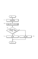
- FIG. 3 shows a flowchart of the interface inspection method according to the present invention, which will be described below based on the flowchart.
- ultrasonic flaw detection is performed using a steel plate having the same specifications as the bottom steel plate 2 to be inspected, and the flaw detection sensitivity of ultrasonic flaw detection is set in the pulser / receiver 14 in advance. Shall. Further, the processing after step S2 described below is performed by the arithmetic unit 18.
- Step S1 ultrasonic flaw detection is performed on the composite floor slab 6.
- the transmitting probe 11 and the receiving probe 12 are arranged at desired positions on the outer surface of the bottom steel plate 2, and ultrasonic waves are transmitted from the transmitting probe 11 toward the bottom steel plate 2, The reflected wave from the bottom steel plate 2 is received by the receiving probe 12.
- the frequency of the ultrasonic wave used in this step is appropriately selected according to the thickness of the bottom steel plate 2.
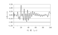
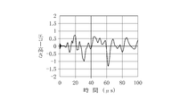
- FIGS. 4A and 4B An example of the waveform of the flaw detection result obtained in this step is shown in FIGS. 4A and 4B.
- FIG. 4A shows the flaw detection result when there is a gap at the interface 8
- FIG. 4B shows the flaw detection result when there is no gap at the interface 8.
- FIG. 4A in which there are voids at the interface 8 multiple reflections of ultrasonic waves occur in the bottom steel plate 2, and the multiple reflection components appear as reflected waves in the flaw detection result graph.
- FIG. 4B showing the flaw detection result in the sound part where no void exists at the interface 8, although multiple reflection of ultrasonic waves occurs in the bottom steel plate 2, some of the multiple reflection components escape into the concrete. As a result, the graph becomes smoother than in FIG. 4A.
- step S2 the frequency analysis of the reflected wave acquired in step S1 is performed. Specifically, fast Fourier transform (hereinafter referred to as FFT) is performed on the signal waveform of the reflected wave obtained in step S1, and the characteristics of frequency and amplitude are graphed. From this graph, it can be confirmed that when there is a gap at the interface 8 between the bottom steel plate 2 and the concrete 4, the amplitude of the frequency band specific to the bottom steel plate 2 is larger than the amplitude when there is no gap. This is because, when there is a gap at the interface 8, if low frequency ultrasonic waves (frequency: 20 kHz to 1 MHz) are incident on the interface 8 between the bottom steel plate 2 and the concrete 4, the ultrasonic waves do not escape into the concrete 4.
- FFT fast Fourier transform
- the bottom steel plate 2 In the bottom steel plate 2, it propagates mainly as a Lamb wave (plate wave) while repeating multiple reflections, mode conversions, and interferences. This is because a frequency component due to longitudinal wave interference shown in (1), that is, a frequency band unique to the bottom steel plate 2 is detected.
- the frequency band specific to the bottom steel plate 2 is obtained from the following equation (1).
- f v / (2 ⁇ t) (1)
- f the frequency band specific to the bottom steel plate 2
- v the speed of sound of the ultrasonic wave propagating through the bottom steel plate 2
- t the plate thickness of the bottom steel plate 2, respectively.
- FIGS. 7A and 7B An example of the result of frequency analysis in this step is shown in FIGS. 7A and 7B, and details will be described later.
- step S3 it is determined whether or not the magnitude of the amplitude in the specific frequency band of the frequency analysis result obtained in step S2 is less than a preset threshold value.
- the threshold value is a value determined that the interface 8 has a void having a size exceeding the allowable range. If the determination result is true (Yes), the process proceeds to step S4. If the determination result is false (No), the process proceeds to step S5.
- the specific frequency band for determining the filling state in this step is a specific frequency band determined according to the thickness of the bottom steel plate 2 to be inspected.
- step S4 since the amplitude in the specific frequency band in the frequency analysis result obtained in step S2 is less than the threshold value, there is no void existing in the interface 8 between the bottom steel plate 2 and the concrete 4, or the interface 8 This flow chart is ended by assuming that the gap existing in is in an allowable range and the filling state of the interface 8 is sufficient.
- step S5 since the amplitude in the specific frequency band in the frequency analysis result obtained in step S2 is equal to or larger than the threshold value, the size of the gap existing at the interface 8 between the bottom steel plate 2 and the concrete 4 is determined. It is determined that the allowable range is exceeded and the filling state of the interface 8 is insufficient, and this flowchart is ended.
- the reason why the filling state of the interface 8 can be identified by performing the above-described steps S1 to S5 is as follows. That is, when fresh concrete is present on the bottom steel plate 2, the longitudinal wave reflection component is partially transmitted into the fresh concrete. On the other hand, when there is no fresh concrete on the bottom steel plate 2, the longitudinal wave reflection component repeats multiple reflections in the bottom steel plate 2. Therefore, by paying attention to the reflection component of the frequency obtained from the above equation (1), it is possible to grasp and identify the filling / unfilling of the fresh concrete 4 on the bottom steel plate 2 by performing the above-described steps. .
- the ultrasonic probes 11 and 12 are arranged at desired positions on the bottom steel plate 2 to perform ultrasonic flaw detection on the composite floor slab 6 and perform frequency analysis of the received waveform to perform a specific analysis.
- the magnitude of the amplitude in the frequency band is compared with a threshold value, and the filling state of the concrete 4 at the interface 8 is determined.
- the transmission probe 11 and the reception probe 12 are applied to respective contact portions that contact the bottom steel plate 2. It is only necessary to remove the glycerin paste. Therefore, the filling state of the interface 8 can be efficiently inspected. And since the ultrasonic probe is used in the interface inspection method of the present invention, it can be used repeatedly for interface inspection of another synthetic floor slab, and the inspection cost can be reduced.
- FIG. 5 is a flowchart when the above-described interface inspection method is applied to the stagnant water inspection.
- steps S11 to S13 are the same as steps S1 to S3 of the interface inspection method described above, and steps S14 and S15 of the determination result are different from steps S4 and S5 described above. Therefore, in this flowchart, steps after step S13 for performing the determination will be described.
- step S13 it is determined whether or not the magnitude of the amplitude in the specific frequency band of the frequency analysis result obtained in step S12 is less than a preset threshold value.
- the threshold value is a value that is determined to be stagnant at the interface 8. If the determination result is true (Yes), the process proceeds to step S14. If the determination result is false (No), the process proceeds to step S15.
- the specific frequency band for determining the stagnant state in this step is a specific frequency band determined according to the thickness of the bottom steel plate 2 to be inspected.
- step S14 since the amplitude in the specific frequency band in the frequency analysis result obtained in step S12 is less than the threshold value, there is a cavity at the interface 8 between the bottom steel plate 2 and the hardened concrete, and the cavity is within the cavity. It determines with having stagnated and complete
- step S15 since the amplitude in the specific frequency band in the frequency analysis result obtained in step S12 is greater than or equal to the threshold value, there is a void at the interface 8 between the bottom steel plate 2 and the hardened concrete. It is determined that there is no water in the flow and this flowchart is terminated.
- the longitudinal wave reflection component represented by the above formula (1) When there is water in the gap formed at the interface 8 between the bottom steel plate 2 and the hardened concrete, the longitudinal wave reflection component represented by the above formula (1) partially permeates into the water. On the other hand, when there is no stagnant water, the longitudinal wave reflection component repeats multiple reflections in the bottom steel plate 2. Accordingly, by paying attention to the reflection component of the frequency obtained from the above-described equation (1), the presence or absence of water in the gap existing at the interface 8 between the bottom steel plate 2 and the hardened concrete is performed by performing the above-described steps S11 to S15. It becomes possible to grasp and identify. As described above, the principle of the stagnant water inspection method of the present modification is the same as that of the interface inspection method of the above embodiment, and therefore the interface inspection method of the above embodiment can be applied to the stagnant water inspection method of the present modification.
- Example 1 Using the interface inspection apparatus 10 according to the present invention, the interface inspection method described above was performed to inspect the filling state of the interface 8 of the composite slab 6 filled with fresh concrete.
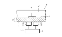
- FIG. 6 Schematic diagram of the interface inspection method performed in this example is shown in FIG.
- a simulated gap 9 having a diameter of 100 mm is formed at the interface 8 between the bottom steel plate 2 and the fresh concrete 4, and the transmitting probe 11 is formed on the outer surface of the bottom steel plate 2 so as to sandwich the simulated gap 9.
- the receiving probe 12 were arranged to perform ultrasonic flaw detection.
- the bottom steel plate 2 having a thickness D of 8 mm was used.
- the frequency of the ultrasonic wave input from the pulsar / receiver 14 to the transmission probe 11 is 250 kHz, and the vertical probe has a transducer diameter of 38.1 mm as the transmission probe 11 and the reception probe 12. I used a child.
- a synthetic floor slab 6 in which no simulated void 9 was formed was prepared, and the above-described interface inspection method was performed.
- the bottom steel plate 2 and the transmission probe 11 have the same specifications as described above, and the ultrasonic frequency used in the interface inspection method is also the same.
- the surface of the fresh concrete 4 is smoothed by applying vibrations to the fresh concrete 4 with a vibrator to bleed air at the interface 8 before performing ultrasonic flaw detection.
- a glycerin paste was used as the contact medium 13.
- FIGS. 7A, 7B, 8A, and 8B The results are shown in FIGS. 7A, 7B, 8A, and 8B.
- FIG. 7A is a graph of the signal processing result of the flaw detection waveform immediately after the fresh concrete 4 is filled in the bottom steel plate 2 in which the simulated gap 9 is formed in the interface 8
- FIG. 7B is the bottom of the healthy part in which no gap is formed in the interface 8.
- FIG. 8A is a graph of the signal processing result of the flaw detection waveform immediately after filling the steel plate 2 with the fresh concrete 4.
- FIG. 8A is a flaw detection waveform 180 minutes after the fresh concrete 4 is filled in the bottom steel plate 2 where the simulated gap 9 exists at the interface 8.
- FIG. 8B is a graph of the signal processing result of the flaw detection waveform 180 minutes after the fresh concrete 4 is filled in the bottom steel plate 2 of the healthy part having no gap at the interface 8.
- the frequency band is 300 to 450 kHz. It can be seen that the amplitude is significantly increased in the range of. This is because the ultrasonic wave multiple-reflected by the bottom steel plate 2 does not escape into the fresh concrete 4 due to the simulated air gap 9 and appears in the frequency band of 300 to 450 kHz which is the natural frequency band of the bottom steel plate 2. is there.
- the frequency band is 300 to 450 kHz. There is no noticeable amplitude in the range. This is because the simulated air gap 9 does not exist at the interface 8, so that the ultrasonic waves that have been multiple-reflected in the bottom steel plate 2 escape into the fresh concrete 4, so that the multiple reflection components are present in the natural frequency band of the bottom steel plate 2. It will not appear.
- the filled fresh concrete 4 is gradually hardened over time, but from FIG. 8A, when there is a simulated void 9 at the interface 8, the fresh concrete 4 is gradually hardened. Even in this case, a peak appears in the frequency band of 300 to 450 kHz, which indicates that the simulated air gap 9 can be detected.
- FIGS. 8A and 8B show that the filling state of the interface 8 can be inspected by the interface inspection method of the present invention even if the state of the fresh concrete 4 changes with time.
- the filling state of the interface 8 can be easily grasped by performing the interface inspection between the bottom steel plate 2 and the fresh concrete 4 by the interface inspection method according to the present invention.
- Example 2 Using the interface inspection apparatus 10 according to the present invention, the interface inspection method according to the present invention described above was performed to inspect the filling state of the interface 8 of the composite slab 6 filled with concrete.
- the present embodiment is different from the first embodiment in that the composite floor slab 6 composed of the bottom steel plate 2 and the hardened concrete 4 ′ is the inspection target, and other configurations and inspection conditions are the same as described above. The same as in the first embodiment.
- FIGS. 9A to 9D The survey results are shown in FIGS. 9A to 9D.
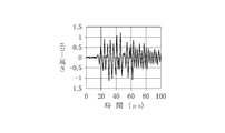
- FIG. 9A shows the flaw detection result of the composite floor slab 6 in which the simulated gap 9 is formed.
- FIG. 9B is a graph obtained by performing FFT on the waveform of FIG. 9A.
- FIG. 9C shows the flaw detection result of the composite floor slab 6 in which the simulated gap 9 is not formed, and
- FIG. 9D is a graph obtained by performing FFT on the waveform of FIG. 9C.
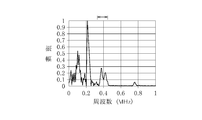
- FIG. 9B shows that the amplitude is remarkably increased in the frequency band of 300 to 450 kHz which is the natural frequency band of the bottom steel plate 2 due to the influence of the multiple reflection in the bottom steel plate 2 by the simulated gap 9. I know that. For this reason, the interface inspection method of the present invention can also be applied to the interface inspection of concrete after curing.
- Example 3 Using the interface inspection apparatus 10 according to the present invention, the water stagnation inspection at the interface 8 of the composite floor slab 6 ′ filled with concrete was performed using the water stagnation inspection method which is a modified example of the present invention described above.
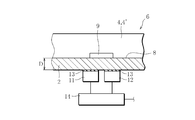
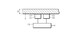
- FIG. 10 shows a schematic diagram of the water leakage inspection method performed in this example.
- a simulated gap 9 having a diameter of 100 mm is formed at the interface 8 between the bottom steel plate 2 and the hardened concrete 4 ′.
- Ultrasonic flaw detection was performed by placing the transmitting probe 11 and the receiving probe 12 on the outer surface of the bottom steel plate 2 so as to sandwich the simulated gap 9.
- the bottom steel plate 2 having a thickness D of 8 mm was used.
- the frequency of the ultrasonic wave incident on the bottom steel plate 2 and the diameters of the transmitting probe 11 and the receiving probe 12 are the same as in the first embodiment.
- a synthetic floor slab 6 in which a simulated gap 9 having a diameter of 100 mm is formed at the interface 8 between the bottom steel plate 2 and the hardened concrete 4 ′ is prepared, and a similar water leakage test is performed. Went.
- FIG. 11A is a graph showing flaw detection results when the bottom steel plate 2 in which the simulated gap 9 is formed is filled with concrete and hardened, and then the gap portion of the simulated gap 9 is stagnated.
- FIG. 11B is a graph of FIG.
- FIG. 11C is a graph showing the result of signal processing of the flaw detection waveform
- FIG. 11C is a graph showing the flaw detection result after the bottom steel plate 2 in which the simulated air gap 9 is formed is filled with concrete and cured
- FIG. 11D is the flaw detection waveform of FIG. The graph which shows the result of having processed the signal is shown.
- FIG. 11B in the graph of the result obtained by applying the interface inspection method of the present invention to the synthetic slab 6 ′ in which the simulated void 9 is formed in the interface 8 and the simulated void 9 is stagnant, Although the amplitude appears in the frequency band of 300 to 450 kHz, no conspicuous amplitude is seen.
- FIG. 11D in the graph obtained as a result of applying the interface inspection method of the present invention to the composite floor slab 6 in which the simulated gap 9 is formed at the interface 8, the frequency band is in the range of 300 to 450 kHz. It can be seen that the amplitude is significantly larger than that in FIG. 11B.
- the interface inspection method of the present invention is also applicable to a water-stagnation test for identifying a water-stagnation state in a gap formed at the interface 8.
- Example 4 Using the interface inspection apparatus 10 according to the present invention, the interface inspection method described in the above embodiment was performed, and the filling state of the interface 8 of the synthetic slab 6 filled with fresh concrete 4 was inspected.
- FIGS. Schematic diagrams of the interface inspection method performed in this example are shown in FIGS.
- the bottom steel plate 2 corresponding to the unfilled concrete 4 is not prepared.
- gap 9 was not formed in the interface 8 was prepared as a comparative example.
- the synthetic floor slab 6 of this example prepared the synthetic floor slab 6 immediately after filling the fresh concrete 4 and the synthetic floor slab 6 one hour after filling the fresh concrete 4.
- a gel sheet having a thickness of 5 mm was used as the contact medium 13.
- the thickness D of the bottom steel plate 2 is the same as that in the first embodiment.
- FIG. 14A is a graph showing a flaw detection result obtained by performing ultrasonic flaw detection using a gel sheet as the contact medium 13 on the bottom steel plate 2 not filled with concrete
- FIG. 14B is a graph showing a signal processing result of the flaw detection waveform of FIG.
- FIG. 14C is a graph showing the flaw detection result obtained by performing ultrasonic flaw detection using the gel sheet as the contact medium 13 on the bottom steel plate 2 immediately after filling with the fresh concrete 4
- FIG. 14D shows the signal processing result of the flaw detection waveform of FIG. 14C.
- FIG. 14E is a graph showing a flaw detection result obtained by performing ultrasonic flaw detection using a gel sheet as a contact medium on the bottom steel plate 60 minutes after filling with fresh concrete
- FIG. 14F is a flaw detection waveform of FIG. 14E. It is a graph which shows a signal processing result.
- the amplitude in the frequency band of 300 to 450 kHz is remarkably large. It has become.
- FIGS. 14D and 14F in the graph of the result obtained by applying the interface inspection method of the present invention to the composite floor slab 6 in which the simulated void is not formed, the frequency band is in the range of 300 to 450 kHz. Although the amplitude is seen, it can be seen that it is smaller than that in FIG. 14B. From these results, even when a gel sheet is used as the contact medium 13, the filling state of the interface 8 of the composite floor slab 6 can be well distinguished.
- frequency analysis by FFT is performed on the reflected wave received by the receiving probe 12, but instead of the frequency analysis, only a specific frequency of the received signal waveform is passed.
- the wavelet transform after converting the received signal obtained by ultrasonic flaw detection, the time axis information remains in addition to the characteristics of frequency and amplitude, and an analysis method such as sum / product of arbitrary components is used. Is possible and preferable.
- the said embodiment demonstrated determining the filling state of the interface 8 by the interface inspection method, when it determines with the filling state of the interface 8 being inadequate in the said step S3, the bottom steel plate 2 of a flaw detection location.
- a vibrator or the like may be installed to compact the concrete 4, and the filling state of the interface 8 may be inspected again by the interface inspection method described above. Thereby, the desired location of the interface 8 can be easily inspected.
- the state of the interface 8 can be grasped before the concrete 4 is hardened, it is not necessary to repair the concrete 4 by hardening a hole in the steel plate after the concrete 4 is hardened. Can be improved.
- the interface inspection method of the present invention is applied to the interface 8 of the fresh concrete 4, the interface 8 of the concrete 4 ′ after curing, and the presence of water remaining in the interface 8, but is not limited thereto.
Landscapes
- Physics & Mathematics (AREA)
- General Physics & Mathematics (AREA)
- Pathology (AREA)
- Life Sciences & Earth Sciences (AREA)
- Chemical & Material Sciences (AREA)
- Analytical Chemistry (AREA)
- Biochemistry (AREA)
- Health & Medical Sciences (AREA)
- Immunology (AREA)
- General Health & Medical Sciences (AREA)
- Engineering & Computer Science (AREA)
- Signal Processing (AREA)
- Acoustics & Sound (AREA)
- Mathematical Physics (AREA)
- Spectroscopy & Molecular Physics (AREA)
- Investigating Or Analyzing Materials By The Use Of Ultrasonic Waves (AREA)
Description
本発明は、複合構造体の界面検査方法及び装置に係り、特に複合構造体の界面の状態を検査する界面検査方法及び装置に関する。
一般に、橋梁等の複合構造体では、側鋼板を有し、主桁上部と剛結された底鋼板の枠内に鉄筋を配設し、その枠内にコンクリートを打設して合成床版を構築する工法が知られている。この枠内にコンクリートを充填すると、底鋼板とコンクリートとの界面に空隙が生じてしまうことがある。このような空隙内の空気が抜けきらずに、コンクリート硬化後にも空隙が残ってしまうと、複合構造体の強度及び耐久性の低下を引き起こしてしまう虞がある。このため、充填されたコンクリートが硬化する前に、底鋼板とコンクリートとの界面の状態を検査する方法が求められていた。
そこで、このような複合構造体において、所定の周波数範囲で連続的に変化する電気信号を圧電スピーカに入力し、圧電スピーカの周波数-電圧特性におけるピーク電圧の位置や大きさの変化を検出することで、コンクリートの充填状態を検査する方法が知られている(特許文献1参照)。
しかしながら、上記特許文献1に開示された方法では、圧電センサが小型であるために、圧電センサを配置した場所でしかコンクリートの充填状態を把握できず、局所的な情報しか得られない。また、橋梁等の大型複合構造体に適用しようとすると、複合構造体全体の界面状態の情報を得るには多数の圧電センサが必要になり、ケーブルの本数の増加により煩雑な施工状況となる他、検査コストが増大してしまうため好ましくない。
また、充填状態の検査が終了すると、底鋼板とコンクリートとの界面から外部に延びる圧電センサのケーブルを切断してコンクリート等に埋めるという後処理を行うという煩わしさがあった。さらに、検査に使用した圧電センサは使い捨てになってしまい、別の複合構造体の検査へ使い回すことができなかった。
また、充填状態の検査が終了すると、底鋼板とコンクリートとの界面から外部に延びる圧電センサのケーブルを切断してコンクリート等に埋めるという後処理を行うという煩わしさがあった。さらに、検査に使用した圧電センサは使い捨てになってしまい、別の複合構造体の検査へ使い回すことができなかった。
また、コンクリートが硬化して底鋼板とコンクリートとの界面に空隙が形成されてしまうと、底鋼板やコンクリートを補強している鉄筋やスタッド等の補強部材が、空隙に雨水等の水が侵入することにより腐食してしまうことが懸念される。このような補強部材が腐食してしまうと、複合構造体の強度が低下してしまう虞がある。このため底鋼板とコンクリートとからなる複合構造体の界面に形成された空隙における滞水の有無を識別するための検査手法も求められていた。
本発明はこのような課題に鑑みてなされたものであり、その目的とするところは、複合構造体の所望の箇所の界面の状態を容易に検査することのできる界面検査方法及び装置を提供することにある。
上記目的を達成するため、本発明の界面検査方法は、検査対象の複合構造体を構成する部材に適した周波数の超音波を発生させる超音波発生手段により前記複合構造体に超音波を送信し、前記複合構造体からの反射波を受信手段で受信して信号波形を取得する工程と、取得した信号波形を信号処理し、周波数に対する信号の振幅特性を取得する工程と、信号処理された信号波形における、前記複合構造体固有の周波数帯域の振幅に基づいて、前記複合構造体の界面の状態を判定する工程と、を有することを特徴とする。
上述した信号処理する工程では、前記取得した信号波形に対して周波数解析を行うようにしてもよい。
または、上述した信号処理する工程では、前記取得した信号波形の特定の周波数成分を通過させるバンドパスフィルタで処理してもよい。
上述した界面の状態は、鋼板とフレッシュコンクリートとからなる複合構造体の界面における前記フレッシュコンクリートの充填状態であってもよい。
または、上述した界面の状態は、鋼板と硬化したコンクリートとからなる複合構造体の界面における滞水の状態であってもよい。
本発明の界面検査装置は、検査対象の複合構造体に、前記複合構造体を構成する部材に適した周波数の超音波を加える超音波発生手段と、前記複合構造体からの反射波を受信して信号波形を取得する受信手段と、前記受信手段で受信した信号波形を信号処理し、周波数に対する信号の振幅特性を取得する信号処理手段と、信号処理された波形信号における、前記複合構造体固有の周波数帯域の振幅に基づいて、前記複合構造体の界面の状態を判定する判定手段と、を備えることを特徴とする。
本発明の界面検査方法及び装置によれば、複合構造体に適した周波数の超音波を加え、複合構造体からの反射波を受信して信号処理し、複合構造体固有の周波数帯域における振幅から、複合構造体の界面の状態を判定する。従って、複合構造体の所望の位置の界面の状態を複合構造体固有の周波数帯域における振幅に基づいて容易に検査することができるので、複合構造体を全体的に検査することで、複合構造体全体の界面の状態を把握することができる。
以下、図面に基づき本発明の一実施形態について説明する。
図1は、本発明に係る複合構造体の界面検査装置の概略構成図である。本実施形態では、複合構造体の一例として底鋼板2とフレッシュコンクリート4とからなる合成床版6を用いて説明する。界面検査装置10は、例えば橋梁の桁上部に設けられた、底鋼板2とコンクリート4とからなる合成床版6における底鋼板2とコンクリート4との界面8の状態を検査するための装置である。本発明で底鋼板2として使用する鋼板の厚さDは、1~100mmが好ましく、5~25mmであるのがより好ましい。コンクリート4は、硬化する前のコンクリート、即ちフレッシュコンクリートである。
図1は、本発明に係る複合構造体の界面検査装置の概略構成図である。本実施形態では、複合構造体の一例として底鋼板2とフレッシュコンクリート4とからなる合成床版6を用いて説明する。界面検査装置10は、例えば橋梁の桁上部に設けられた、底鋼板2とコンクリート4とからなる合成床版6における底鋼板2とコンクリート4との界面8の状態を検査するための装置である。本発明で底鋼板2として使用する鋼板の厚さDは、1~100mmが好ましく、5~25mmであるのがより好ましい。コンクリート4は、硬化する前のコンクリート、即ちフレッシュコンクリートである。
図1に示すように界面検査装置10は、送信用探触子(振動発生手段)11、受信用探触子(受信手段)12、パルサー/レシーバ14、アナログ/デジタル変換器(以下、A/D変換器という)16、演算装置18、及びモニタ24を備える。
送信用探触子11は、所定の周波数の超音波を送受信するパルサー/レシーバ14に接続され、パルサー/レシーバ14から送信された周波数の超音波を底鋼板2に送信する。パルサー/レシーバ14は、20kHz~1MHzの範囲で設定された周波数の超音波を送信用探触子11に入力する。
受信用探触子12は、パルサー/レシーバ14に接続されており、底鋼板2内で反射した反射波を受信する。図1に示すように、送信用探触子11及び受信用探触子12は底鋼板2の外側の所望の位置に配置される。送信用探触子11及び受信用探触子12が底鋼板2に当接するそれぞれの当接箇所には、超音波を底鋼板2に効率よく伝達するための接触媒質13としてグリセリンペーストが塗布されている。
なお、超音波を効率よく伝達するための接触媒質13として、グリセリンペーストの代わりに、例えば軟質のエラストマーからなるゲルシート等、超音波を伝達可能な媒質を用いてもよい。接触媒質13としてゲルシートを用いる場合、その硬度は、送信用探触子11及び受信用探触子12により押圧されると変形可能な硬さであり、例えば硬度アスカーC30以下であるのが好ましい。また、ゲルシートの厚さは、送信用探触子11及び受信用探触子12により押圧されて変形して薄くなっても、その薄くなった部分が所定の厚さになるのが好ましい。さらにゲルシートは、周囲の温度変化に対するエラストマーの性質が安定しているので、季節に依らず、特に夏の暑い時期や冬の寒い時期でも安定した接触状態となる。また、接触媒質13としてゲルシートを用いた場合には、ゲルシートを剥がすだけでよく、特別な後処理は不要である。また、ゲルシートの大きさは、底鋼板2の接触面2aにゲルシートを介して接する送信用探触子11、受信用探触子12の接触面の面積と略等しい大きさにするのが好ましい。
図2に示すように、底鋼板2の接触面2aに歪みがある場合、送信用探触子11及び受信用探触子12と接触面2aとの間にグリセリンペースト等の液状の接触媒質では埋めることの困難な隙間Sが生じてしまうことがある。このような場合に接触媒質13としてゲルシートを用いることによって、ゲルシートが隙間Sを埋めて、接触面2aに対する送信用探触子11及び受信用探触子12の追従性を向上させつつ超音波の送信及び反射波の受信を行うことができるので、検査精度を維持することができる。なお、送信用探触子11及び受信用探触子12をより小型化することによって、底鋼板2の接触面2aとの接触面積が小さくなるので、接触面2aに歪みがある場合でも隙間Sの形成を極力低減することができることは言うまでもない。
受信用探触子12で受信された反射波は、パルサー/レシーバ14で電気信号に変換される。電気信号に変換された反射波は、A/D変換器16でデジタル信号に変換され、演算装置18で信号処理される。詳しくは、演算装置18は信号処理部(信号処理手段)20と判定部(判定手段)22とを備え、信号処理部20で反射波の周波数解析を行い、解析結果をモニタ24に表示する。判定部22は、信号処理部20で解析処理された反射波から合成床版6の底鋼板2とコンクリート4との界面8の状態を判定するものである。なお、図示しないが、演算装置18は報知部を備えていてもよく、判定部22の判定結果に応じて当該報知部を用いて報知してもよい。また、図示しないが演算装置18はROM、RAM等のメモリを有しており、当該メモリには以下に説明する閾値等が設定されている。
以下、このように構成された界面検査装置10を用いて、合成床版6の界面8を検査する界面検査方法について説明する。図3には、本発明に係る界面検査方法のフローチャートが示されており、当該フローチャートに基づいて以下に説明する。なお、本発明の界面検査方法の事前準備として、検査対象の底鋼板2と同仕様の鋼板を用いて超音波探傷を行い、超音波探傷の探傷感度を予めパルサー/レシーバ14に設定しているものとする。また、以下に説明するステップS2以降の処理は、演算装置18で行われるものである。
ステップS1では、合成床版6の超音波探傷を行う。詳しくは、底鋼板2の外側面の所望の位置に送信用探触子11及び受信用探触子12を配置し、送信用探触子11から底鋼板2に向けて超音波を送信し、底鋼板2からの反射波を受信用探触子12で受信する。本ステップで使用される超音波の周波数は、底鋼板2の厚さに応じて適宜選択される。
本ステップで得られる探傷結果の波形の一例を図4A、図4Bに示す。図4Aは界面8に空隙がある場合の探傷結果を示しており、図4Bは界面8に空隙がない場合の探傷結果を示している。界面8に空隙が存在する図4Aでは、底鋼板2内で超音波の多重反射が起こり、その多重反射成分が反射波として探傷結果のグラフに現れている。一方、界面8に空隙が存在しない健全部での探傷結果を表す図4Bでは、底鋼板2内で超音波の多重反射が起こるものの、その多重反射成分の一部がコンクリート内に抜けてしまうため、図4Aと比べて滑らかなグラフとなる。
ステップS2では、上記ステップS1で取得した反射波の周波数解析を行う。詳しくは、上記ステップS1で得られた反射波の信号波形に対して高速フーリエ変換(Fast Fourier Transform、以下FFTという)を行い、周波数と振幅との特性をグラフ化する。このグラフから、底鋼板2とコンクリート4との界面8に空隙がある場合に、底鋼板2固有の周波数帯域の振幅の大きさが、空隙のない場合の振幅より大きくなることが確認できる。これは、界面8に空隙が存在する場合、底鋼板2とコンクリート4との界面8に低周波数超音波(周波数:20kHz~1MHz)を入射させると、超音波は、コンクリート4内に抜けていかずに底鋼板2内で多重反射、モード変換、干渉を繰り返しながら主にLamb波(板波)として伝搬するため、反射波の成分は、底鋼板2に入射した超音波の周波数と、以下の式(1)に示される縦波の干渉による周波数成分、即ち底鋼板2固有の周波数帯域とに検出されるからである。底鋼板2固有の周波数帯域は、以下の式(1)より求められる。
f=v/(2×t) ・・・(1)
ここで、f:底鋼板2固有の周波数帯域、v:底鋼板2を伝搬する超音波の音速、t:底鋼板2の板厚をそれぞれ示している。本ステップでの周波数解析の結果の一例を図7A、図7Bに示しており、詳細については後述する。
f=v/(2×t) ・・・(1)
ここで、f:底鋼板2固有の周波数帯域、v:底鋼板2を伝搬する超音波の音速、t:底鋼板2の板厚をそれぞれ示している。本ステップでの周波数解析の結果の一例を図7A、図7Bに示しており、詳細については後述する。
ステップS3では、上記ステップS2で得られた周波数解析結果の特定の周波数帯域における振幅の大きさが、予め設定された閾値未満であるか否かを判定する。当該閾値は、界面8に許容範囲を超える大きさの空隙があると判定される値である。当該判定結果が真(Yes)の場合にはステップS4に進み、一方偽(No)の場合にはステップS5へ進む。本ステップで充填状態を判定するための特定の周波数帯域は、検査対象の底鋼板2の厚さに応じて決まる固有の周波数帯域である。
ステップS4では、上記ステップS2で得られた周波数解析結果での特定の周波数帯域における振幅が閾値未満であったので、底鋼板2とコンクリート4との界面8に存在する空隙が無い、または界面8に存在する空隙は許容範囲内の大きさであり、界面8の充填状態は十分であるとして本フローチャートを終了する。
一方、ステップS5では、上記ステップS2で得られた周波数解析結果での特定の周波数帯域における振幅が閾値以上であったので、底鋼板2とコンクリート4との界面8に存在する空隙の大きさが許容範囲を超えており、界面8の充填状態が不十分であると判定して本フローチャートを終了する。
上述したステップS1~S5を行うことで界面8の充填状態が識別可能となるのは、以下の理由による。即ち、底鋼板2上にフレッシュコンクリートが存在する場合、縦波の反射成分はフレッシュコンクリート中へ一部透過する。一方、底鋼板2上にフレッシュコンクリートが存在しない場合、縦波の反射成分は底鋼板2内で多重反射を繰り返す。従って上記式(1)から求められる周波数の反射成分に着目することで、上述した各ステップを行い底鋼板2上でのフレッシュコンクリート4の充填/未充填を把握し、識別することが可能となる。
このように、本実施形態では、底鋼板2に超音波探触子11、12を所望の位置に配置して合成床版6の超音波探傷を行い、受信波形の周波数解析を行って特定の周波数帯域における振幅の大きさを閾値と比較し、界面8のコンクリート4の充填状態を判定する。これにより、界面8の所望の箇所を検査できるので、合成床版6全体を検査することで界面8全体の充填状態を把握することができる。また、超音波探傷で得られた受信信号を周波数解析することによって周波数と振幅との特性が得られるので、特定の周波数帯域における振幅の大きさを確認することで界面8の状態を容易に把握することができる。
さらに、界面検査終了後の処理として、接触媒質としてグリセリンペーストを用いた場合には、送信用探触子11及び受信用探触子12が底鋼板2に当接するそれぞれの当接箇所に塗布されたグリセリンペーストを除去するだけでよい。従って界面8の充填状態の検査を効率よく行うことができる。そして、本発明の界面検査方法では超音波探触子を使用するので、別の合成床版の界面検査にも繰り返して使用することができ、検査費用を低減することができる。
<変形例>
上記実施形態に係る界面検査方法の変形例について以下に述べる。この変形例では、上述した界面検査方法を利用して底鋼板と硬化したコンクリートとの界面に形成された空隙の滞水の有無を検査する点が異なっており、その他の構成については共通しているので説明を省略する。
上記実施形態に係る界面検査方法の変形例について以下に述べる。この変形例では、上述した界面検査方法を利用して底鋼板と硬化したコンクリートとの界面に形成された空隙の滞水の有無を検査する点が異なっており、その他の構成については共通しているので説明を省略する。
図5は、上述した界面検査方法を滞水検査に適用した場合のフローチャートである。本フローチャートは、ステップS11~S13が上述した界面検査方法のステップS1~S3と同じ手順であり、判定結果のステップS14、S15が上述したステップS4、S5と異なっている。従って本フローチャートでは、判定を行うステップS13以降について説明する。
ステップS13では、ステップS12で得られた周波数解析結果の特定の周波数帯域における振幅の大きさが、予め設定された閾値未満であるか否かを判定する。当該閾値は、界面8に滞水があると判定される値である。当該判定結果が真(Yes)の場合にはステップS14に進み、偽(No)の場合にはステップS15へ進む。本ステップで滞水状態を判定するための特定の周波数帯域とは、検査対象の底鋼板2の厚さに応じて決まる固有の周波数帯域のことである。
ステップS14では、ステップS12で得られた周波数解析結果での特定の周波数帯域における振幅が閾値未満であったので、底鋼板2と硬化したコンクリートとの界面8に空洞があり、且つその空洞内に滞水していると判定して本フローチャートを終了する。
一方ステップS15では、ステップS12で得られた周波数解析結果での特定の周波数帯域における振幅が閾値以上であったので、底鋼板2と硬化したコンクリートとの界面8に空隙が存在するものの、その空隙内に滞水していないと判定して本フローチャートを終了する。
底鋼板2と硬化したコンクリートとの界面8に形成された空隙に滞水がある場合には、上述した式(1)で表される縦波の反射成分は滞水中へ一部透過する。一方、滞水が存在しない場合には、縦波の反射成分は底鋼板2内で多重反射を繰り返す。従って上述した式(1)から求められる周波数の反射成分に着目することで、上述したステップS11~S15を行い底鋼板2と硬化したコンクリートとの界面8に存在する空隙内の滞水の有無を把握し、識別することが可能となる。このように本変形例の滞水検査方法は、上記実施形態の界面検査方法と原理が同じなので、上記実施形態の界面検査方法を本変形例の滞水検査方法に適用可能である。
以下、本発明について実施例を挙げて説明するが、本発明は以下の実施例に限定されるものではない。
<実施例1>
本発明に係る界面検査装置10を用いて、上述した界面検査方法を行い、フレッシュコンクリートが充填された合成床版6の界面8の充填状態の検査を行った。
本発明に係る界面検査装置10を用いて、上述した界面検査方法を行い、フレッシュコンクリートが充填された合成床版6の界面8の充填状態の検査を行った。
本実施例で行う界面検査方法の概略図を図6に示す。合成床版6には、底鋼板2とフレッシュコンクリート4との界面8に直径100mmの模擬空隙9を形成し、模擬空隙9を挟むように、底鋼板2の外側面に送信用探触子11と受信用探触子12とを配置して超音波探傷を行った。ここで、底鋼板2は厚さDが8mmのものを使用した。パルサー/レシーバ14から送信用探触子11に入力された超音波の周波数は250kHzであり、送信用探触子11及び受信用探触子12として振動子の直径が38.1mmの垂直探触子を使用した。また、比較例として、模擬空隙9を形成していない合成床版6を準備して、上述した界面検査方法を行った。底鋼板2、送信用探触子11は上記と同じ仕様であり、界面検査方法で使用した超音波の周波数も同じである。なお、いずれの場合も、超音波探傷を行う前に、フレッシュコンクリート4にバイブレータによる振動を加えて界面8の空気を抜き、フレッシュコンクリート4の表面ならしを行っている。また、接触媒質13としてグリセリンペーストを使用した。
結果を図7A、図7B、図8A、図8Bに示す。図7Aは界面8に模擬空隙9が形成された底鋼板2にフレッシュコンクリート4を充填した直後の探傷波形の信号処理結果のグラフ、図7Bは界面8に空隙が形成されていない健全部の底鋼板2にフレッシュコンクリート4を充填した直後の探傷波形の信号処理結果のグラフ、図8Aは界面8に模擬空隙9が存在する底鋼板2にフレッシュコンクリート4を充填してから180分後の探傷波形の信号処理結果のグラフ、図8Bは界面8に空隙のない健全部の底鋼板2にフレッシュコンクリート4を充填してから180分後の探傷波形の信号処理結果のグラフである。
図7A、図8Aに示すように、界面8に模擬空隙9が形成された合成床版6に上述した本発明の界面検査方法を適用して得られた結果のグラフでは、周波数帯域300~450kHzの範囲で振幅が顕著に大きくなっているのが判る。これは、模擬空隙9があるために底鋼板2で多重反射した超音波がフレッシュコンクリート4内へ抜けていかずに、底鋼板2の固有周波数帯域である300~450kHzの周波数帯に出現するためである。(例えば底鋼板2を伝搬する超音波の音速v=5920[m/s]の場合、底鋼板2の板厚t=8[mm]なので底鋼板2固有の周波数帯域は上記式(1)からf=370[kHz]と求められる)。
一方、界面8に模擬空隙9が形成されていない合成床版6に本発明の界面検査方法を適用して得た結果のグラフでは、図7B、図8Bに示すように、周波数帯域300~450kHzの範囲に目立った振幅は見られない。これは、界面8に模擬空隙9が存在しないので、底鋼板2内で多重反射した超音波がフレッシュコンクリート4内に抜けていってしまうため、底鋼板2の固有周波数帯域にその多重反射成分が出現しなくなるからである。
図8A、図8Bにおいて、充填されたフレッシュコンクリート4は時間経過と共に徐々に硬化していっているが、図8Aから、界面8に模擬空隙9がある場合には、フレッシュコンクリート4が徐々に硬化していても、300~450kHzの周波数帯にピークが出現しており、模擬空隙9の検出が可能であることが判る。
従って、図8A、図8Bは、フレッシュコンクリート4の状態が時間経過と共に変化しても、本発明の界面検査方法で界面8の充填状態を検査できることを示している。このように、本発明に係る界面検査方法で底鋼板2とフレッシュコンクリート4との界面検査を行うことで、界面8の充填状態を容易に把握できることが判る。
<実施例2>
本発明に係る界面検査装置10を用いて、上述した本発明に係る界面検査方法を行い、コンクリートが充填された合成床版6の界面8の充填状態の検査を行った。なお、本実施例は、上記実施例1に対し、底鋼板2と硬化したコンクリート4’から構成されている合成床版6を検査対象としている点が異なり、他の構成及び検査条件は上述した実施例1と同様である。
本発明に係る界面検査装置10を用いて、上述した本発明に係る界面検査方法を行い、コンクリートが充填された合成床版6の界面8の充填状態の検査を行った。なお、本実施例は、上記実施例1に対し、底鋼板2と硬化したコンクリート4’から構成されている合成床版6を検査対象としている点が異なり、他の構成及び検査条件は上述した実施例1と同様である。
調査結果を図9A~図9Dに示す。図9Aは模擬空隙9が形成されている合成床版6の探傷結果を示している。図9Bは、図9Aの波形に対してFFTを行ってグラフ化したものである。図9Cは模擬空隙9が形成されていない合成床版6の探傷結果を示しており、図9Dは図9Cの波形に対してFFTを行ってグラフ化したものである。図9Dと比べて図9Bは、模擬空隙9による底鋼板2内での多重反射の影響により、底鋼板2の固有周波数帯域である300~450kHzの周波数帯に振幅が顕著に大きくなって現れていることが判る。このことから、本発明の界面検査方法は、硬化後のコンクリートの界面検査にも適用可能である。
<実施例3>
本発明に係る界面検査装置10を用いて、上述した本発明の変形例である滞水検査方法を利用し、コンクリートが充填された合成床版6’の界面8における滞水検査を行った。
本発明に係る界面検査装置10を用いて、上述した本発明の変形例である滞水検査方法を利用し、コンクリートが充填された合成床版6’の界面8における滞水検査を行った。
本実施例で行う滞水検査方法の概略図を図10に示す。合成床版6’には、底鋼板2と硬化後のコンクリート4’との界面8に直径100mmの模擬空隙9を形成し、模擬空隙9内には水を充填して滞水した状態とした。模擬空隙9を挟むように、底鋼板2の外側面に送信用探触子11と受信用探触子12とを配置して超音波探傷を行った。ここで、底鋼板2は厚さDが8mmのものを使用した。底鋼板2に入射した超音波の周波数、及び送信用探触子11、受信用探触子12の直径は上記実施例1と同様である。また比較例として、図6に示すように、底鋼板2と硬化後のコンクリート4’との界面8に直径100mmの模擬空隙9を形成した合成床版6を準備して、同様の滞水検査を行った。
結果を図11A~図11Dに示す。図11Aは、模擬空隙9が形成されている底鋼板2にコンクリートを充填して硬化させた後に模擬空隙9の空隙部を滞水させた場合の探傷結果を表すグラフ、図11Bは図11Aの探傷波形を信号処理した結果を示すグラフ、図11Cは模擬空隙9が形成されている底鋼板2にコンクリートを充填して硬化させた後の探傷結果を表すグラフ、図11Dは図11Cの探傷波形を信号処理した結果を示すグラフを示している。
図11Bに示すように、界面8に模擬空隙9が形成され、且つ模擬空隙9が滞水している合成床版6’に本発明の界面検査方法を適用して得られた結果のグラフでは、周波数帯域300~450kHzの範囲で振幅が現れているものの目立った振幅は見られない。しかしながら、図11Dに示すように、界面8に模擬空隙9が形成された合成床版6に本発明の界面検査方法を適用して得られた結果のグラフでは、周波数帯域300~450kHzの範囲の振幅が図11Bに比べて顕著に大きくなっていることが判る。
模擬空隙9が滞水していると、底鋼板2で多重反射した超音波が水中に抜けていってしまうため図11Bのように目立った振幅は見られないが、模擬空隙9が滞水していない、つまり空隙であると、上述したように底鋼板2で超音波の多重反射が起こるため、図11Dのように顕著に大きい振幅が現れる。このように本発明の界面検査方法は、界面8に形成された空隙における滞水状態を識別する滞水検査にも適用可能であることが判る。
<実施例4>
本発明に係る界面検査装置10を用いて、上記実施形態で説明した界面検査方法を行い、フレッシュコンクリート4が充填された合成床版6の界面8の充填状態を検査した。
本発明に係る界面検査装置10を用いて、上記実施形態で説明した界面検査方法を行い、フレッシュコンクリート4が充填された合成床版6の界面8の充填状態を検査した。
本実施例で行う界面検査方法の概略図を図12、図13に示す。図12に示すように、コンクリート4を充填しない未充填に相当する底鋼板2を準備した。また、図13に示すように、比較例として界面8に模擬空隙9が形成されていない合成床版6を準備した。本実施例の合成床版6は、フレッシュコンクリート4を充填した直後の合成床版6、及びフレッシュコンクリート4を充填してから1時間後の合成床版6を準備した。本実施例では、接触媒質13として厚さ5mmのゲルシートを用いた。底鋼板2の厚さDは、上記実施例1と同様である。
結果を図14A~図14Fに示す。図14Aは、コンクリートが未充填の底鋼板2に接触媒質13としてゲルシートを用いて超音波探傷を行った探傷結果を表すグラフ、図14Bは、図14Aの探傷波形の信号処理結果を示すグラフ、図14Cは、フレッシュコンクリート4を充填した直後の底鋼板2に接触媒質13としてゲルシートを用いて超音波探傷を行った探傷結果を表すグラフ、図14Dは、図14Cの探傷波形の信号処理結果を示すグラフ、図14Eは、フレッシュコンクリートを充填してから60分後の底鋼板に接触媒質としてゲルシートを用いて超音波探傷を行った探傷結果を表すグラフ、図14Fは、図14Eの探傷波形の信号処理結果を示すグラフである。
図14Bに示すように、コンクリート4が未充填の場合の底鋼板2に本発明の界面検査方法を適用して得られた結果のグラフでは、周波数帯域300~450kHzの範囲の振幅が顕著に大きくなっている。また、図14D、図14Fに示すように、模擬空隙を形成しなかった合成床版6に本発明の界面検査方法を適用して得られた結果のグラフでは、周波数帯域300~450kHzの範囲の振幅が見られるものの、図14Bに比べて小さいことが判る。これらの結果から、接触媒質13としてゲルシートを用いても、合成床版6の界面8の充填状態を良好に判別可能である。
以上で実施形態及び実施例の説明を終えるが、本発明は上述した実施形態及び実施例に限定されるものではない。
例えば、上記実施形態では、受信用探触子12で受信した反射波に対してFFTによる周波数解析を行っているが、周波数解析の代わりに、受信した信号波形の特定の周波数のみを通過させるバンドパスフィルタ(アナログ・デジタルを問わない)や、周波数解析の1つであるウェーブレット変換を行うようにしてもよい。特にウェーブレット変換では、超音波探傷で得られた受信信号を変換した後も、周波数と振幅との特性に加えて時間軸の情報が残り、任意の成分同士の和・積等の解析方法を用いることが可能となり、好ましい。
例えば、上記実施形態では、受信用探触子12で受信した反射波に対してFFTによる周波数解析を行っているが、周波数解析の代わりに、受信した信号波形の特定の周波数のみを通過させるバンドパスフィルタ(アナログ・デジタルを問わない)や、周波数解析の1つであるウェーブレット変換を行うようにしてもよい。特にウェーブレット変換では、超音波探傷で得られた受信信号を変換した後も、周波数と振幅との特性に加えて時間軸の情報が残り、任意の成分同士の和・積等の解析方法を用いることが可能となり、好ましい。
さらに、上記実施形態では、界面検査方法で界面8の充填状態を判定することについて説明したが、上記ステップS3で界面8の充填状態が不十分と判定された場合に、探傷箇所の底鋼板2にバイブレータ等を設置してコンクリート4の締め固めを行い、再度上述した界面検査方法で界面8の充填状態を検査するようにしてもよい。これにより、界面8の所望の場所を容易に検査することができる。また、コンクリート4が硬化する前に界面8の状態を把握することができるので、コンクリート4が硬化した後に鋼板に孔を開けて空隙にコンクリート等を充填する補修を行う必要はなくなり、作業効率を向上させることができる。
そして、上記各実施例ではフレッシュコンクリート4の界面8、硬化後のコンクリート4’の界面8、及び界面8における滞水の有無の検査に本発明の界面検査方法を適用したが、これに限られず、例えば積層された繊維強化プラスチックの層の剥離や、ゴムを型に流し込み硬化させる注型において、ゴムと型との界面の充填状態、例えばゴムが流れないために生じる空洞の検査等にも適用可能である。
2 底鋼板
4、4’ コンクリート
8 界面
10 界面検査装置
11 送信用探触子(振動発生手段)
12 受信用探触子(受信手段)
18 演算装置
20 信号処理部
22 判定部
4、4’ コンクリート
8 界面
10 界面検査装置
11 送信用探触子(振動発生手段)
12 受信用探触子(受信手段)
18 演算装置
20 信号処理部
22 判定部
Claims (6)
- 検査対象の複合構造体を構成する部材に適した周波数の超音波を発生させる超音波発生手段により前記複合構造体に超音波を送信し、前記複合構造体からの反射波を受信手段で受信して信号波形を取得する工程と、
取得した信号波形を信号処理し、周波数に対する信号の振幅特性を取得する工程と、
信号処理された信号波形における、前記複合構造体固有の周波数帯域の振幅に基づいて、前記複合構造体の界面の状態を判定する工程と、
を有することを特徴とする複合構造体の界面検査方法。 - 前記信号処理する工程では、前記取得した信号波形に対して周波数解析を行うことを特徴とする請求項1に記載の複合構造体の界面検査方法。
- 前記信号処理する工程では、前記取得した信号波形の特定の周波数成分を通過させるバンドパスフィルタで処理することを特徴とする請求項1に記載の複合構造体の界面検査方法。
- 前記界面の状態は、鋼板とフレッシュコンクリートとからなる複合構造体の界面における前記フレッシュコンクリートの充填状態であることを特徴とする請求項1乃至3のいずれか1項に記載の複合構造体の界面検査方法。
- 前記界面の状態は、鋼板と硬化したコンクリートとからなる複合構造体の界面における滞水の状態であることを特徴とする請求項1乃至3のいずれか1項に記載の複合構造体の界面検査方法。
- 検査対象の複合構造体に、前記複合構造体を構成する部材に適した周波数の超音波を加える超音波発生手段と、
前記複合構造体からの反射波を受信して信号波形を取得する受信手段と、
前記受信手段で受信した信号波形を信号処理し、周波数に対する信号の振幅特性を取得する信号処理手段と、
信号処理された波形信号における、前記複合構造体固有の周波数帯域の振幅に基づいて、前記複合構造体の界面の状態を判定する判定手段と、
を備えることを特徴とする複合構造体の界面検査装置。
Priority Applications (3)
| Application Number | Priority Date | Filing Date | Title |
|---|---|---|---|
| EP13830901.8A EP2889613A4 (en) | 2012-08-21 | 2013-08-19 | METHOD AND DEVICE FOR INSPECTING COMPOSITE STRUCTURE INTERFACE |
| JP2014531620A JP5909285B2 (ja) | 2012-08-21 | 2013-08-19 | 複合構造体の界面検査方法及び装置 |
| US14/617,293 US20150153313A1 (en) | 2012-11-28 | 2015-02-09 | Interface inspection method and apparatus for composite structure |
Applications Claiming Priority (4)
| Application Number | Priority Date | Filing Date | Title |
|---|---|---|---|
| JP2012-182329 | 2012-08-21 | ||
| JP2012182329 | 2012-08-21 | ||
| JP2012259955 | 2012-11-28 | ||
| JP2012-259955 | 2012-11-28 |
Related Child Applications (1)
| Application Number | Title | Priority Date | Filing Date |
|---|---|---|---|
| US14/617,293 Continuation US20150153313A1 (en) | 2012-11-28 | 2015-02-09 | Interface inspection method and apparatus for composite structure |
Publications (1)
| Publication Number | Publication Date |
|---|---|
| WO2014030615A1 true WO2014030615A1 (ja) | 2014-02-27 |
Family
ID=50149924
Family Applications (1)
| Application Number | Title | Priority Date | Filing Date |
|---|---|---|---|
| PCT/JP2013/072117 Ceased WO2014030615A1 (ja) | 2012-08-21 | 2013-08-19 | 複合構造体の界面検査方法及び装置 |
Country Status (3)
| Country | Link |
|---|---|
| EP (1) | EP2889613A4 (ja) |
| JP (1) | JP5909285B2 (ja) |
| WO (1) | WO2014030615A1 (ja) |
Cited By (6)
| Publication number | Priority date | Publication date | Assignee | Title |
|---|---|---|---|---|
| EP3088884A1 (en) * | 2015-04-28 | 2016-11-02 | Uniper Technologies Limited | Method and system for ultrasonically determining the condition of a building structure |
| WO2017150046A1 (ja) | 2016-03-01 | 2017-09-08 | 三菱電機株式会社 | 超音波測定装置及び超音波測定方法 |
| JP2018179790A (ja) * | 2017-04-14 | 2018-11-15 | 日立造船株式会社 | 空隙判定方法、空隙判定システム及び弾性波検出方法 |
| JP2019023583A (ja) * | 2017-07-24 | 2019-02-14 | 株式会社駒井ハルテック | 測定装置及び測定方法 |
| US10302600B2 (en) | 2016-01-19 | 2019-05-28 | Northrop Grumman Innovation Systems, Inc. | Inspection devices and related systems and methods |
| JP2022526837A (ja) * | 2019-04-17 | 2022-05-26 | ディーエムシー グローバル インコーポレイテッド | 多層構造の物品における強固な結合と弱い結合の間の結合境界を特定する方法及びシステム |
Families Citing this family (1)
| Publication number | Priority date | Publication date | Assignee | Title |
|---|---|---|---|---|
| KR102516411B1 (ko) * | 2022-12-27 | 2023-03-31 | 성균관대학교산학협력단 | 지상투과레이더를 활용한 교량상판 내부체수를 계측하는 방법 및 이의 기록매체 |
Citations (3)
| Publication number | Priority date | Publication date | Assignee | Title |
|---|---|---|---|---|
| JPS61254850A (ja) * | 1985-05-07 | 1986-11-12 | Bridgestone Corp | 接着部の非破壊検査方法 |
| JPH08105864A (ja) * | 1994-09-30 | 1996-04-23 | Hihakai Kensa Kk | 弾性波パルスを用いた試験装置及び試験方法 |
| JP3883466B2 (ja) | 2001-10-29 | 2007-02-21 | 曙ブレーキ工業株式会社 | 充填物検知方法及び充填物検知装置 |
Family Cites Families (2)
| Publication number | Priority date | Publication date | Assignee | Title |
|---|---|---|---|---|
| SU1158920A1 (ru) * | 1983-08-04 | 1985-05-30 | Петрозаводский государственный университет им.О.В.Куусинена | Устройство дл ультразвукового контрол качества неоднородных бетонных конструкций |
| JPH04323553A (ja) * | 1991-04-23 | 1992-11-12 | Nippon Steel Corp | 超音波共振探傷方法および装置 |
-
2013
- 2013-08-19 EP EP13830901.8A patent/EP2889613A4/en not_active Withdrawn
- 2013-08-19 WO PCT/JP2013/072117 patent/WO2014030615A1/ja not_active Ceased
- 2013-08-19 JP JP2014531620A patent/JP5909285B2/ja not_active Expired - Fee Related
Patent Citations (3)
| Publication number | Priority date | Publication date | Assignee | Title |
|---|---|---|---|---|
| JPS61254850A (ja) * | 1985-05-07 | 1986-11-12 | Bridgestone Corp | 接着部の非破壊検査方法 |
| JPH08105864A (ja) * | 1994-09-30 | 1996-04-23 | Hihakai Kensa Kk | 弾性波パルスを用いた試験装置及び試験方法 |
| JP3883466B2 (ja) | 2001-10-29 | 2007-02-21 | 曙ブレーキ工業株式会社 | 充填物検知方法及び充填物検知装置 |
Non-Patent Citations (5)
| Title |
|---|
| ARISA YANAGIHARA ET AL.: "Choonpa ni yoru Hagane Concrete Gosei Shoban no Concrete Mijuten Kenshutsu Gijutsu no Kaihatsu to Jikki eno Tekiyo Kento", DAI 7 KAI DOROKYO SHOBAN SYMPOSIUM RONBUN HOKOKUSHU, 21 June 2012 (2012-06-21), pages 155 - 160, XP055190885 * |
| ARISA YANAGIHARA ET AL.: "Development and Application of Non-Destructive Inspection for Steel-Concrete Composite Structures", JOURNAL OF IHI TECHNOLOGIES, vol. 53, no. L, 1 March 2013 (2013-03-01), pages 47 - 53, XP055191244 * |
| HAJIME IINO ET AL.: "Concrete Filling Capacity and Quality Assurance Procedure Using Nondestructive Tests for Steel-Concrete Composite Slab (QS Slab)", MIYAJI GIHO, vol. 21, 2006, pages 66 - 73, XP008176465 * |
| HIROKI YOSHIO ET AL.: "Seikeigata Hagane Type no Gosei Shoban no Concrete Jutensei Kakunin Hoho ni Kansuru Kosatsu", PROCEEDINGS OF THE 61ST ANNUAL CONFERENCE OF THE JAPAN SOCIETY OF CIVIL ENGINEERS, September 2006 (2006-09-01), pages 115 - 116, XP008176347 * |
| See also references of EP2889613A4 * |
Cited By (8)
| Publication number | Priority date | Publication date | Assignee | Title |
|---|---|---|---|---|
| EP3088884A1 (en) * | 2015-04-28 | 2016-11-02 | Uniper Technologies Limited | Method and system for ultrasonically determining the condition of a building structure |
| US10302600B2 (en) | 2016-01-19 | 2019-05-28 | Northrop Grumman Innovation Systems, Inc. | Inspection devices and related systems and methods |
| US10962506B2 (en) | 2016-01-19 | 2021-03-30 | Northrop Grumman Systems Corporation | Inspection devices and related systems and methods |
| WO2017150046A1 (ja) | 2016-03-01 | 2017-09-08 | 三菱電機株式会社 | 超音波測定装置及び超音波測定方法 |
| US11193912B2 (en) | 2016-03-01 | 2021-12-07 | Mitsubishi Electric Corporation | Ultrasonic measurement apparatus and ultrasonic measurement method |
| JP2018179790A (ja) * | 2017-04-14 | 2018-11-15 | 日立造船株式会社 | 空隙判定方法、空隙判定システム及び弾性波検出方法 |
| JP2019023583A (ja) * | 2017-07-24 | 2019-02-14 | 株式会社駒井ハルテック | 測定装置及び測定方法 |
| JP2022526837A (ja) * | 2019-04-17 | 2022-05-26 | ディーエムシー グローバル インコーポレイテッド | 多層構造の物品における強固な結合と弱い結合の間の結合境界を特定する方法及びシステム |
Also Published As
| Publication number | Publication date |
|---|---|
| JPWO2014030615A1 (ja) | 2016-07-28 |
| EP2889613A1 (en) | 2015-07-01 |
| JP5909285B2 (ja) | 2016-04-26 |
| EP2889613A4 (en) | 2016-05-04 |
Similar Documents
| Publication | Publication Date | Title |
|---|---|---|
| JP5909285B2 (ja) | 複合構造体の界面検査方法及び装置 | |
| EP3070467B1 (en) | Ultrasonic test system, ultrasonic test method and method of manufacturing aircraft part | |
| Sun et al. | Nondestructive evaluation of steel-concrete composite structure using high-frequency ultrasonic guided wave | |
| Li et al. | Debonding detection in CFRP-reinforced steel structures using anti-symmetrical guided waves | |
| Aseem et al. | Debonding detection in rebar-reinforced concrete structures using second harmonic generation of longitudinal guided wave | |
| JP4938050B2 (ja) | 超音波診断評価装置 | |
| JP5403976B2 (ja) | コンクリート構造物品質検査方法 | |
| US20100319455A1 (en) | Damage volume and depth estimation | |
| Zhu et al. | Detection of delamination between steel bars and concrete using embedded piezoelectric actuators/sensors | |
| JP2012141230A (ja) | 非破壊検査装置 | |
| Stepinski | Novel instrument for inspecting rock bolt integrity using ultrasonic guided waves | |
| JP2004085370A (ja) | 配管検査方法及び装置 | |
| JP6130778B2 (ja) | 複合構造体の界面検査方法及び装置 | |
| Rosalie et al. | Variation in the group velocity of Lamb waves as a tool for the detection of delamination in GLARE aluminium plate-like structures | |
| US20150153313A1 (en) | Interface inspection method and apparatus for composite structure | |
| KR100955783B1 (ko) | 응력파를 이용한 콘크리트 구조물의 비파괴검사 방법 | |
| KR101027069B1 (ko) | 숏크리트 접착상태 평가 방법 | |
| JP4405821B2 (ja) | 超音波信号検出方法及び装置 | |
| JP5517374B1 (ja) | 複合構造体の界面検査方法、界面検査装置、及び界面検査プログラム | |
| CN113074850B (zh) | 一种应力应变测量方法 | |
| Wang et al. | Rayleigh wave-based crack monitoring of mortar coating on prestressed concrete cylinder pipe under internal pressure | |
| JP2013088239A (ja) | 合成構造体の欠陥面積率算出装置及び欠陥面積率算出方法 | |
| JP2002195989A (ja) | 構造物の非破壊検査方法 | |
| JP2013088238A (ja) | 合成構造体の欠陥面積率算出装置及び欠陥面積率算出方法 | |
| CN114441075B (zh) | 一种配电电缆接头机械应力超声评估方法及系统 |
Legal Events
| Date | Code | Title | Description |
|---|---|---|---|
| 121 | Ep: the epo has been informed by wipo that ep was designated in this application |
Ref document number: 13830901 Country of ref document: EP Kind code of ref document: A1 |
|
| ENP | Entry into the national phase |
Ref document number: 2014531620 Country of ref document: JP Kind code of ref document: A |
|
| WWE | Wipo information: entry into national phase |
Ref document number: 2013830901 Country of ref document: EP |
|
| NENP | Non-entry into the national phase |
Ref country code: DE |