WO2014033818A1 - 非可逆機構 - Google Patents
非可逆機構 Download PDFInfo
- Publication number
- WO2014033818A1 WO2014033818A1 PCT/JP2012/071614 JP2012071614W WO2014033818A1 WO 2014033818 A1 WO2014033818 A1 WO 2014033818A1 JP 2012071614 W JP2012071614 W JP 2012071614W WO 2014033818 A1 WO2014033818 A1 WO 2014033818A1
- Authority
- WO
- WIPO (PCT)
- Prior art keywords
- plate
- brake lining
- output shaft
- brake
- ball
- Prior art date
- Legal status (The legal status is an assumption and is not a legal conclusion. Google has not performed a legal analysis and makes no representation as to the accuracy of the status listed.)
- Ceased
Links
Images

Classifications
-
- F—MECHANICAL ENGINEERING; LIGHTING; HEATING; WEAPONS; BLASTING
- F16—ENGINEERING ELEMENTS AND UNITS; GENERAL MEASURES FOR PRODUCING AND MAINTAINING EFFECTIVE FUNCTIONING OF MACHINES OR INSTALLATIONS; THERMAL INSULATION IN GENERAL
- F16D—COUPLINGS FOR TRANSMITTING ROTATION; CLUTCHES; BRAKES
- F16D51/00—Brakes with outwardly-movable braking members co-operating with the inner surface of a drum or the like
- F16D51/10—Brakes with outwardly-movable braking members co-operating with the inner surface of a drum or the like shaped as exclusively radially-movable brake-shoes
- F16D51/12—Brakes with outwardly-movable braking members co-operating with the inner surface of a drum or the like shaped as exclusively radially-movable brake-shoes mechanically actuated
-
- F—MECHANICAL ENGINEERING; LIGHTING; HEATING; WEAPONS; BLASTING
- F16—ENGINEERING ELEMENTS AND UNITS; GENERAL MEASURES FOR PRODUCING AND MAINTAINING EFFECTIVE FUNCTIONING OF MACHINES OR INSTALLATIONS; THERMAL INSULATION IN GENERAL
- F16D—COUPLINGS FOR TRANSMITTING ROTATION; CLUTCHES; BRAKES
- F16D43/00—Automatic clutches
- F16D43/02—Automatic clutches actuated entirely mechanically
-
- F—MECHANICAL ENGINEERING; LIGHTING; HEATING; WEAPONS; BLASTING
- F16—ENGINEERING ELEMENTS AND UNITS; GENERAL MEASURES FOR PRODUCING AND MAINTAINING EFFECTIVE FUNCTIONING OF MACHINES OR INSTALLATIONS; THERMAL INSULATION IN GENERAL
- F16D—COUPLINGS FOR TRANSMITTING ROTATION; CLUTCHES; BRAKES
- F16D65/00—Parts or details
- F16D65/14—Actuating mechanisms for brakes; Means for initiating operation at a predetermined position
- F16D65/16—Actuating mechanisms for brakes; Means for initiating operation at a predetermined position arranged in or on the brake
- F16D65/22—Actuating mechanisms for brakes; Means for initiating operation at a predetermined position arranged in or on the brake adapted for pressing members apart, e.g. for drum brakes
-
- F—MECHANICAL ENGINEERING; LIGHTING; HEATING; WEAPONS; BLASTING
- F16—ENGINEERING ELEMENTS AND UNITS; GENERAL MEASURES FOR PRODUCING AND MAINTAINING EFFECTIVE FUNCTIONING OF MACHINES OR INSTALLATIONS; THERMAL INSULATION IN GENERAL
- F16D—COUPLINGS FOR TRANSMITTING ROTATION; CLUTCHES; BRAKES
- F16D2121/00—Type of actuator operation force
- F16D2121/14—Mechanical
-
- F—MECHANICAL ENGINEERING; LIGHTING; HEATING; WEAPONS; BLASTING
- F16—ENGINEERING ELEMENTS AND UNITS; GENERAL MEASURES FOR PRODUCING AND MAINTAINING EFFECTIVE FUNCTIONING OF MACHINES OR INSTALLATIONS; THERMAL INSULATION IN GENERAL
- F16D—COUPLINGS FOR TRANSMITTING ROTATION; CLUTCHES; BRAKES
- F16D2125/00—Components of actuators
- F16D2125/18—Mechanical mechanisms
- F16D2125/20—Mechanical mechanisms converting rotation to linear movement or vice versa
- F16D2125/34—Mechanical mechanisms converting rotation to linear movement or vice versa acting in the direction of the axis of rotation
- F16D2125/36—Helical cams, Ball-rotating ramps
-
- F—MECHANICAL ENGINEERING; LIGHTING; HEATING; WEAPONS; BLASTING
- F16—ENGINEERING ELEMENTS AND UNITS; GENERAL MEASURES FOR PRODUCING AND MAINTAINING EFFECTIVE FUNCTIONING OF MACHINES OR INSTALLATIONS; THERMAL INSULATION IN GENERAL
- F16D—COUPLINGS FOR TRANSMITTING ROTATION; CLUTCHES; BRAKES
- F16D2125/00—Components of actuators
- F16D2125/18—Mechanical mechanisms
- F16D2125/58—Mechanical mechanisms transmitting linear movement
- F16D2125/66—Wedges
-
- F—MECHANICAL ENGINEERING; LIGHTING; HEATING; WEAPONS; BLASTING
- F16—ENGINEERING ELEMENTS AND UNITS; GENERAL MEASURES FOR PRODUCING AND MAINTAINING EFFECTIVE FUNCTIONING OF MACHINES OR INSTALLATIONS; THERMAL INSULATION IN GENERAL
- F16D—COUPLINGS FOR TRANSMITTING ROTATION; CLUTCHES; BRAKES
- F16D41/00—Freewheels or freewheel clutches
- F16D41/06—Freewheels or freewheel clutches with intermediate wedging coupling members between an inner and an outer surface
- F16D41/08—Freewheels or freewheel clutches with intermediate wedging coupling members between an inner and an outer surface with provision for altering the freewheeling action
- F16D41/10—Freewheels or freewheel clutches with intermediate wedging coupling members between an inner and an outer surface with provision for altering the freewheeling action with self-actuated reversing
Definitions
- the present invention relates to a power transmission system for general industrial machines, aircraft equipment, etc., and relates to a non-reciprocal mechanism that does not transmit rotation to an input shaft even when a load acts on the output shaft.
- the nonreciprocal mechanism a1 includes a ball ramp portion a4 interposed between the input shaft a2 and the output shaft a3, and the load torque acting on the output shaft a3 by the ball ramp portion a4. It has a configuration for generating a brake torque by converting the rotational driving force into an axial load and applying the load to the multi-plate brake a5 (see, for example, Patent Document 1).
- the multi-plate brake a5 for generating the brake torque is formed by arranging a large number of friction plates a6 in the axial direction, so that the irreversible mechanism including such a multi-plate brake a5 is used.
- the total length in the axial direction of a1 becomes long and the number of parts increases.
- the total length of the nonreciprocal mechanism a1 in the axial direction becomes long, the total length of the housing a8 that accommodates the input shaft a2, the output shaft a3, the friction plate a6, and the like becomes long.
- disadvantages occur in terms of weight and cost.
- the present invention focuses on the above points, and an object of the present invention is to provide an irreversible mechanism having a short overall length, a small number of parts, and a light weight.
- the irreversible mechanism according to the present invention performs the following control. That is, the irreversible mechanism according to the present invention has an input shaft that receives an input of rotational driving force, an output shaft that receives torque from the input shaft, and a radial force when load torque acts on the output shaft. A ball ramp portion to be generated, a brake lining that receives the radial force from the ball ramp portion, and a brake drum that presses against the brake lining when the brake lining receives the radial force from the ball ramp portion And a housing that houses the input shaft, the output shaft, the ball ramp portion, the brake lining, and the brake drum.
- the ball ramp portion when a load torque is applied to the output shaft, the ball ramp portion generates a radial force, and this radial force is used to press the brake lining against the brake drum for input. Since the transmission of rotation to the shaft can be prevented, the overall length can be shortened and the number of parts and weight can be reduced as compared with the conventional nonreciprocal mechanism using other plate brakes.
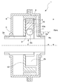
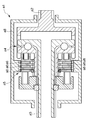
- FIG. 2 is a cross-sectional view taken along line AA according to FIG. 1. Schematic which shows the conventional irreversible mechanism.
- the irreversible mechanism 1 is used for an aircraft flap drive mechanism or the like, and as shown in FIGS. 1 and 2, an input shaft 2 that receives input of rotational driving force, and torque from the input shaft 2 An output shaft 3 that receives the transmission, a ball ramp portion 4 that generates a radial force when a load torque acts on the output shaft 3, and a brake lining 5 that receives the radial force from the ball ramp portion 4 A brake drum 6 that presses against the brake lining 5 when the brake lining 5 receives the radial force from the ball ramp portion 4, the input shaft 2, the output shaft 3, the ball ramp portion 4, the brake And a housing 8 for accommodating the lining 5 and the brake drum 6 therein.
- the input shaft 2 includes an input end 2a connected to a drive source at one end in the axial direction, and the output shaft 3 is engaged with the output shaft 3 at the other end.
- a key 2b for driving is integrally provided.
- the keys 2b are provided at three locations in the present embodiment, and the keys 2b adjacent to each other are separated from each other by 120 ° in the circumferential direction.
- a gap is interposed between the key 2b and the first plate 9 provided integrally with the output shaft 3.
- the output shaft 3 includes an output end 3 a connected to an object to be driven at one axial end, and a circumferential end at the other end is a key 2 b of the input shaft 2.
- the first plate 9 that receives the rotational driving force from the input shaft 2 and collides with the ball ramp portion 4 is integrally provided.
- the ball lamp portion 4 is provided integrally with the output shaft 3 as described above, and has the first ball lamp 9a radially outward at the center in the circumferential direction.
- the first plate 9 is provided at three locations in the present embodiment, and the key 2 b of the input shaft 2 is disposed between the first plates 9 adjacent to each other.
- the second plate 10 is provided at three places in the present embodiment, and the key 2b of the input shaft 2 is arranged between the second plates 10 adjacent to each other.
- the ball 11 is arranged between the first and second ball lamps 9a and 10a in the circumferential center of the first and second plates 9 and 10, and the first plate 9 and the second plate The plate 10 is closest to the radial direction.
- the ball 11 is By rolling and moving on the first and second ball lamps 9a and 10a, the second plate 10 is urged and moved in a direction away from the first plate 9 in the radial direction, that is, outward in the radial direction. Then, a radially outward force is transmitted to the brake lining 5.
- the brake lining 5 is provided on the outer side of the second plate 10 and can be engaged with a positioning protrusion 10 b provided on the outer surface of the second plate 10. It has a recess 5a. In the present embodiment, the brake lining 5 is also provided at three locations.
- a compression coil spring 7 is disposed between the brake lining 5 and the second plate 10 as an urging means for applying a preload force radially outward to the brake lining 5. .
- Carriers 12 are arranged on both sides of the brake lining 5 in the axial direction to prevent the brake lining 5 from falling off.
- the brake lining 5 receives the transmission of the outward force in the radial direction and receives the force transmitted to the brake drum 6. Crimp.
- the brake drum 6 has a substantially cylindrical shape as shown in FIGS. 1 and 2, and the inner surface thereof faces the outer surface of the brake lining 5.
- the brake drum 6 is fixed to the housing 8.
- the load torque and the brake torque are in a proportional relationship.
- Tout load torque
- Tbrk brake torque
- Rbrk, Rb, q are fixed parameters, so by specifying the friction coefficient m, The relationship of Tout ⁇ Tbrk can be maintained regardless of the value of Tout.
- Rbrk Effective brake radius
- Rb Effective ball ramp radius
- s Ball ramp angle
- the second plate is driven by the key 2b.
- the plate 10 is pushed by the input shaft key 2b, and the plate 9 is rotated by the load torque. Therefore, the output shaft 3, the plate 10, and the brake lining 5 always rotate while maintaining the phase difference S1.
- the ball ramp portion 4 when a load torque is applied to the output shaft 3, the ball ramp portion 4 generates a radial force, and the brake lining 5 is utilized using the radial force. Is prevented from being transmitted to the input shaft 2 by being pressed against the brake drum 6. Therefore, the overall length can be shortened and the number of parts and the weight can be reduced as compared with the conventional nonreciprocal mechanism using other plate brakes.
- the second plate of the ball ramp portion and the brake lining are configured separately, and a compression coil spring as an urging means is interposed between them.
- the second plate of the part and the brake lining may be integrally formed, and the urging means may be interposed between the first plate and the second plate of the ball ramp part.
- the number of keys of the ball ramp unit and the input shaft is set to three.
- the number of keys of the ball ramp unit and the input shaft may be set to any number other than three. Good.
- non-reciprocal mechanism of the present invention is not limited to the aircraft flap drive mechanism exemplified in the description of the above-described embodiment, and may of course be used in general power transmission systems such as general industrial machines and aircraft equipment.
Landscapes
- Engineering & Computer Science (AREA)
- General Engineering & Computer Science (AREA)
- Mechanical Engineering (AREA)
- Braking Arrangements (AREA)
Description
Tbrk = Tout *m *Rbrk / (Rb *tan (q) ) = k * Tout (k = m *Rbrk / (Rb *tan (q) ))
(Tout:負荷トルク、Tbrk:ブレーキトルク)
と表され、Rbrk、Rb、qは、固定パラメータであるため、摩擦係数mを規定することで、
Tout< Tbrkの関係をToutの値に関係なく維持することができる。
(Rbrk:有効ブレーキ半径、Rb:有効ボールランプ半径、s:ボールランプ角)
(図1、2を参照)
ここで、入力軸キー2bと、プレート9、10との隙間は、この回転位相以上にする必要がある。
2…入力軸
3…出力軸
4…ボールランプ部
5…ブレーキライニング
6…ブレーキドラム
8…ハウジング
Claims (2)
- 回転駆動力の入力を受け付ける入力軸と、この入力軸からトルクの伝達を受ける出力軸と、この出力軸に負荷トルクが作用した際にラジアル方向の力を発生させるボールランプ部と、このボールランプ部から前記ラジアル方向の力を受けるブレーキライニングと、このブレーキライニングが前記ボールランプ部から前記ラジアル方向の力を受けた際に前記ブレーキライニングと圧着するブレーキドラムと、これら入力軸、出力軸、ボールランプ部、ブレーキライニング、ブレーキドラム及び付勢手段を内部に収納するハウジングとを備えていることを特徴とする非可逆機構。
- 前記ブレーキライニング5が前記ボールランプ部を構成する第2のプレートの外方に設けられており、前記第2のプレートの外面に設けた位置決め突起と係合可能な位置決め凹部を有する請求項1記載の非可逆機構。
Priority Applications (4)
| Application Number | Priority Date | Filing Date | Title |
|---|---|---|---|
| EP12883469.4A EP2889504B1 (en) | 2012-08-27 | 2012-08-27 | Irreversible mechanism |
| PCT/JP2012/071614 WO2014033818A1 (ja) | 2012-08-27 | 2012-08-27 | 非可逆機構 |
| US14/424,366 US9470280B2 (en) | 2012-08-27 | 2012-08-27 | Irreversible mechanism |
| JP2014532599A JP6003991B2 (ja) | 2012-08-27 | 2012-08-27 | 非可逆機構 |
Applications Claiming Priority (1)
| Application Number | Priority Date | Filing Date | Title |
|---|---|---|---|
| PCT/JP2012/071614 WO2014033818A1 (ja) | 2012-08-27 | 2012-08-27 | 非可逆機構 |
Publications (1)
| Publication Number | Publication Date |
|---|---|
| WO2014033818A1 true WO2014033818A1 (ja) | 2014-03-06 |
Family
ID=50182669
Family Applications (1)
| Application Number | Title | Priority Date | Filing Date |
|---|---|---|---|
| PCT/JP2012/071614 Ceased WO2014033818A1 (ja) | 2012-08-27 | 2012-08-27 | 非可逆機構 |
Country Status (4)
| Country | Link |
|---|---|
| US (1) | US9470280B2 (ja) |
| EP (1) | EP2889504B1 (ja) |
| JP (1) | JP6003991B2 (ja) |
| WO (1) | WO2014033818A1 (ja) |
Cited By (3)
| Publication number | Priority date | Publication date | Assignee | Title |
|---|---|---|---|---|
| DE102014011336A1 (de) * | 2014-07-30 | 2016-02-04 | Liebherr-Aerospace Lindenberg Gmbh | Rücklaufsperre mit radial wirkenden Bremselementen |
| JP2017206229A (ja) * | 2016-03-14 | 2017-11-24 | ザ・ボーイング・カンパニーThe Boeing Company | ブローバック防止装置、及び関連する方法 |
| JP2024512887A (ja) * | 2022-03-07 | 2024-03-21 | 唐澤交通器材(泰州)有限公司 | 自転車用クラッチ式拡張ブレーキ |
Families Citing this family (3)
| Publication number | Priority date | Publication date | Assignee | Title |
|---|---|---|---|---|
| USD771540S1 (en) * | 2015-06-15 | 2016-11-15 | Saf-Holland, Inc. | Brake spider |
| EP3222869B1 (en) * | 2016-03-24 | 2020-05-06 | Goodrich Actuation Systems Limited | Torque limiting device |
| EP3480070B1 (en) | 2017-11-02 | 2020-10-07 | Goodrich Actuation Systems Limited | Braking device |
Citations (6)
| Publication number | Priority date | Publication date | Assignee | Title |
|---|---|---|---|---|
| JPS63115920A (ja) * | 1986-10-31 | 1988-05-20 | Ogura Clutch Co Ltd | 電磁ブレ−キ |
| JPH04261987A (ja) * | 1991-02-15 | 1992-09-17 | Toyota Motor Corp | ウインドレギュレータ |
| JP2006214523A (ja) | 2005-02-03 | 2006-08-17 | Shimadzu Corp | 非可逆機構を有するトルク伝達装置 |
| JP2006347412A (ja) * | 2005-06-17 | 2006-12-28 | Shimano Inc | ローラブレーキ取付アダプタ |
| JP2008309222A (ja) * | 2007-06-13 | 2008-12-25 | Ntn Corp | 逆入力防止クラッチ |
| JP2009287605A (ja) * | 2008-05-27 | 2009-12-10 | Denso Corp | クラッチ |
Family Cites Families (5)
| Publication number | Priority date | Publication date | Assignee | Title |
|---|---|---|---|---|
| GB567676A (en) * | 1942-01-13 | 1945-02-27 | Otto Edward Wolff | Improvements in or relating to clutch mechanism |
| US3468403A (en) * | 1967-11-20 | 1969-09-23 | Trw Inc | Multiroller brake and clutch construction |
| JP2007120535A (ja) * | 2005-10-25 | 2007-05-17 | Shimadzu Corp | トルク伝達装置 |
| WO2015162791A1 (ja) * | 2014-04-25 | 2015-10-29 | 株式会社島津製作所 | 非可逆機構 |
| DE102014011336A1 (de) * | 2014-07-30 | 2016-02-04 | Liebherr-Aerospace Lindenberg Gmbh | Rücklaufsperre mit radial wirkenden Bremselementen |
-
2012
- 2012-08-27 WO PCT/JP2012/071614 patent/WO2014033818A1/ja not_active Ceased
- 2012-08-27 EP EP12883469.4A patent/EP2889504B1/en active Active
- 2012-08-27 JP JP2014532599A patent/JP6003991B2/ja active Active
- 2012-08-27 US US14/424,366 patent/US9470280B2/en active Active
Patent Citations (6)
| Publication number | Priority date | Publication date | Assignee | Title |
|---|---|---|---|---|
| JPS63115920A (ja) * | 1986-10-31 | 1988-05-20 | Ogura Clutch Co Ltd | 電磁ブレ−キ |
| JPH04261987A (ja) * | 1991-02-15 | 1992-09-17 | Toyota Motor Corp | ウインドレギュレータ |
| JP2006214523A (ja) | 2005-02-03 | 2006-08-17 | Shimadzu Corp | 非可逆機構を有するトルク伝達装置 |
| JP2006347412A (ja) * | 2005-06-17 | 2006-12-28 | Shimano Inc | ローラブレーキ取付アダプタ |
| JP2008309222A (ja) * | 2007-06-13 | 2008-12-25 | Ntn Corp | 逆入力防止クラッチ |
| JP2009287605A (ja) * | 2008-05-27 | 2009-12-10 | Denso Corp | クラッチ |
Cited By (4)
| Publication number | Priority date | Publication date | Assignee | Title |
|---|---|---|---|---|
| DE102014011336A1 (de) * | 2014-07-30 | 2016-02-04 | Liebherr-Aerospace Lindenberg Gmbh | Rücklaufsperre mit radial wirkenden Bremselementen |
| JP2017206229A (ja) * | 2016-03-14 | 2017-11-24 | ザ・ボーイング・カンパニーThe Boeing Company | ブローバック防止装置、及び関連する方法 |
| JP2024512887A (ja) * | 2022-03-07 | 2024-03-21 | 唐澤交通器材(泰州)有限公司 | 自転車用クラッチ式拡張ブレーキ |
| JP7573120B2 (ja) | 2022-03-07 | 2024-10-24 | 唐澤交通器材(泰州)有限公司 | 自転車用クラッチ式拡張ブレーキ |
Also Published As
| Publication number | Publication date |
|---|---|
| JPWO2014033818A1 (ja) | 2016-08-08 |
| EP2889504A1 (en) | 2015-07-01 |
| EP2889504B1 (en) | 2018-10-10 |
| EP2889504A4 (en) | 2016-10-26 |
| JP6003991B2 (ja) | 2016-10-05 |
| US9470280B2 (en) | 2016-10-18 |
| US20150260242A1 (en) | 2015-09-17 |
Similar Documents
| Publication | Publication Date | Title |
|---|---|---|
| JP6003991B2 (ja) | 非可逆機構 | |
| JP7275874B2 (ja) | クラッチ装置 | |
| JP5272089B1 (ja) | モータサイクル用クラッチ装置 | |
| US10228034B2 (en) | Electric linear motion actuator and electric disk brake system | |
| WO2019064727A1 (ja) | 電動ディスクブレーキ | |
| US9841062B2 (en) | Clutch for vehicle | |
| JP2020029937A (ja) | 摩擦ブレーキ、車載装置 | |
| US20090071789A1 (en) | Power transmitting apparatus | |
| US10001177B2 (en) | Irreversible mechanism | |
| CN108105276B (zh) | 离合器结构 | |
| US6719106B1 (en) | Duplex skewed-roller brake disc | |
| JP3166978U (ja) | 非可逆装置 | |
| WO2017164400A1 (ja) | ブレーキ付モータおよびアクチュエータ | |
| JP7787676B2 (ja) | 電動クラッチ | |
| JP2007332986A (ja) | 非可逆装置 | |
| JP2007120535A (ja) | トルク伝達装置 | |
| JP2006312963A (ja) | トルク伝達装置 | |
| JP3167766U (ja) | 非可逆装置 | |
| JP2017184602A (ja) | ブレーキ付モータ | |
| JP2017089871A (ja) | ディスクブレーキ装置 | |
| JP2017175850A (ja) | アクチュエータ | |
| JP2015197208A (ja) | 多板摩擦係合装置 | |
| CN119435583A (zh) | 转矩限制器 | |
| JP2006220247A (ja) | トルク制限機構を有するトルク伝達装置 | |
| WO2018061628A1 (ja) | クラッチ装置 |
Legal Events
| Date | Code | Title | Description |
|---|---|---|---|
| 121 | Ep: the epo has been informed by wipo that ep was designated in this application |
Ref document number: 12883469 Country of ref document: EP Kind code of ref document: A1 |
|
| ENP | Entry into the national phase |
Ref document number: 2014532599 Country of ref document: JP Kind code of ref document: A |
|
| WWE | Wipo information: entry into national phase |
Ref document number: 2012883469 Country of ref document: EP |
|
| WWE | Wipo information: entry into national phase |
Ref document number: 14424366 Country of ref document: US |
|
| NENP | Non-entry into the national phase |
Ref country code: DE |