WO2014033849A1 - サイリスタ起動装置 - Google Patents
サイリスタ起動装置 Download PDFInfo
- Publication number
- WO2014033849A1 WO2014033849A1 PCT/JP2012/071792 JP2012071792W WO2014033849A1 WO 2014033849 A1 WO2014033849 A1 WO 2014033849A1 JP 2012071792 W JP2012071792 W JP 2012071792W WO 2014033849 A1 WO2014033849 A1 WO 2014033849A1
- Authority
- WO
- WIPO (PCT)
- Prior art keywords
- synchronous machine
- rotational speed
- control angle
- voltage
- phase
- Prior art date
- Legal status (The legal status is an assumption and is not a legal conclusion. Google has not performed a legal analysis and makes no representation as to the accuracy of the status listed.)
- Ceased
Links
Images






Classifications
-
- H—ELECTRICITY
- H02—GENERATION; CONVERSION OR DISTRIBUTION OF ELECTRIC POWER
- H02P—CONTROL OR REGULATION OF ELECTRIC MOTORS, ELECTRIC GENERATORS OR DYNAMO-ELECTRIC CONVERTERS; CONTROLLING TRANSFORMERS, REACTORS OR CHOKE COILS
- H02P27/00—Arrangements or methods for the control of AC motors characterised by the kind of supply voltage
- H02P27/04—Arrangements or methods for the control of AC motors characterised by the kind of supply voltage using variable-frequency supply voltage, e.g. inverter or converter supply voltage
- H02P27/047—V/F converter, wherein the voltage is controlled proportionally with the frequency
-
- H—ELECTRICITY
- H02—GENERATION; CONVERSION OR DISTRIBUTION OF ELECTRIC POWER
- H02P—CONTROL OR REGULATION OF ELECTRIC MOTORS, ELECTRIC GENERATORS OR DYNAMO-ELECTRIC CONVERTERS; CONTROLLING TRANSFORMERS, REACTORS OR CHOKE COILS
- H02P1/00—Arrangements for starting electric motors or dynamo-electric converters
- H02P1/16—Arrangements for starting electric motors or dynamo-electric converters for starting dynamo-electric motors or dynamo-electric converters
- H02P1/46—Arrangements for starting electric motors or dynamo-electric converters for starting dynamo-electric motors or dynamo-electric converters for starting an individual synchronous motor
- H02P1/52—Arrangements for starting electric motors or dynamo-electric converters for starting dynamo-electric motors or dynamo-electric converters for starting an individual synchronous motor by progressive increase of frequency of supply to motor
-
- H—ELECTRICITY
- H02—GENERATION; CONVERSION OR DISTRIBUTION OF ELECTRIC POWER
- H02P—CONTROL OR REGULATION OF ELECTRIC MOTORS, ELECTRIC GENERATORS OR DYNAMO-ELECTRIC CONVERTERS; CONTROLLING TRANSFORMERS, REACTORS OR CHOKE COILS
- H02P1/00—Arrangements for starting electric motors or dynamo-electric converters
- H02P1/16—Arrangements for starting electric motors or dynamo-electric converters for starting dynamo-electric motors or dynamo-electric converters
- H02P1/46—Arrangements for starting electric motors or dynamo-electric converters for starting dynamo-electric motors or dynamo-electric converters for starting an individual synchronous motor
-
- H—ELECTRICITY
- H02—GENERATION; CONVERSION OR DISTRIBUTION OF ELECTRIC POWER
- H02P—CONTROL OR REGULATION OF ELECTRIC MOTORS, ELECTRIC GENERATORS OR DYNAMO-ELECTRIC CONVERTERS; CONTROLLING TRANSFORMERS, REACTORS OR CHOKE COILS
- H02P23/00—Arrangements or methods for the control of AC motors characterised by a control method other than vector control
- H02P23/0086—Arrangements or methods for the control of AC motors characterised by a control method other than vector control specially adapted for high speeds, e.g. above nominal speed
- H02P23/009—Arrangements or methods for the control of AC motors characterised by a control method other than vector control specially adapted for high speeds, e.g. above nominal speed using field weakening
-
- H—ELECTRICITY
- H02—GENERATION; CONVERSION OR DISTRIBUTION OF ELECTRIC POWER
- H02P—CONTROL OR REGULATION OF ELECTRIC MOTORS, ELECTRIC GENERATORS OR DYNAMO-ELECTRIC CONVERTERS; CONTROLLING TRANSFORMERS, REACTORS OR CHOKE COILS
- H02P27/00—Arrangements or methods for the control of AC motors characterised by the kind of supply voltage
- H02P27/04—Arrangements or methods for the control of AC motors characterised by the kind of supply voltage using variable-frequency supply voltage, e.g. inverter or converter supply voltage
- H02P27/16—Arrangements or methods for the control of AC motors characterised by the kind of supply voltage using variable-frequency supply voltage, e.g. inverter or converter supply voltage using AC to AC converters without intermediate conversion to DC
-
- H—ELECTRICITY
- H02—GENERATION; CONVERSION OR DISTRIBUTION OF ELECTRIC POWER
- H02P—CONTROL OR REGULATION OF ELECTRIC MOTORS, ELECTRIC GENERATORS OR DYNAMO-ELECTRIC CONVERTERS; CONTROLLING TRANSFORMERS, REACTORS OR CHOKE COILS
- H02P2201/00—Indexing scheme relating to controlling arrangements characterised by the converter used
- H02P2201/13—DC-link of current link type, e.g. typically for thyristor bridges, having an inductor in series with rectifier
-
- H—ELECTRICITY
- H02—GENERATION; CONVERSION OR DISTRIBUTION OF ELECTRIC POWER
- H02P—CONTROL OR REGULATION OF ELECTRIC MOTORS, ELECTRIC GENERATORS OR DYNAMO-ELECTRIC CONVERTERS; CONTROLLING TRANSFORMERS, REACTORS OR CHOKE COILS
- H02P2209/00—Indexing scheme relating to controlling arrangements characterised by the waveform of the supplied voltage or current
- H02P2209/11—Sinusoidal waveform
-
- H—ELECTRICITY
- H02—GENERATION; CONVERSION OR DISTRIBUTION OF ELECTRIC POWER
- H02P—CONTROL OR REGULATION OF ELECTRIC MOTORS, ELECTRIC GENERATORS OR DYNAMO-ELECTRIC CONVERTERS; CONTROLLING TRANSFORMERS, REACTORS OR CHOKE COILS
- H02P27/00—Arrangements or methods for the control of AC motors characterised by the kind of supply voltage
- H02P27/04—Arrangements or methods for the control of AC motors characterised by the kind of supply voltage using variable-frequency supply voltage, e.g. inverter or converter supply voltage
- H02P27/06—Arrangements or methods for the control of AC motors characterised by the kind of supply voltage using variable-frequency supply voltage, e.g. inverter or converter supply voltage using DC to AC converters or inverters
Definitions
- the present invention relates to a thyristor starter, and more particularly to a thyristor starter that starts a synchronous machine.
- the thyristor starter is a converter that converts three-phase AC power into DC power, a DC reactor that smoothes the DC power, and DC power that is supplied from the converter via the DC reactor to three-phase AC power of a desired frequency. And an inverter for conversion and feeding to the synchronous machine.
- the synchronous machine in the stopped state can be started and rotated at a predetermined rotational speed.
- Patent Document 1 Japanese Patent Laid-Open No. 2003-61380 (Patent Document 1)).
- the first conventional method has a problem that the DC voltage appearing on the input terminal side of the inverter increases as the rotational speed of the synchronous machine increases. Since the converter needs to supply a DC voltage higher than the DC voltage appearing on the input terminal side of the inverter, the first method requires a large converter.
- a main object of the present invention is to provide a thyristor starter capable of reducing the size of a converter and improving the utilization efficiency.
- a thyristor starter is a thyristor starter for starting a synchronous machine, which converts a first AC power into a DC power and converts the DC power into a second AC power of a variable frequency.
- the speed calculation unit for determining the rotational speed of the synchronous machine, and the function or table indicating the relationship between the rotational speed of the synchronous machine and the phase control angle of the inverter, the synchronization obtained by the speed calculation unit
- a control angle calculation unit for obtaining a phase control angle having a value corresponding to the rotation speed of the machine, and a control unit for controlling the inverter based on the phase control angle obtained by the control angle calculation unit.
- the phase control angle changes from the minimum value to the maximum value according to the rotational speed of the synchronous machine
- the rate of increase of the phase control angle with respect to the rotational speed of the synchronous machine is a plurality of stages according to the rotational speed of the synchronous machine Be changed.
- the rate of increase of the phase control angle with respect to the rotational speed of the synchronous machine depends on the rotational speed of the synchronous machine so that the DC voltage appearing at the input terminal of the inverter is constant even if the rotational speed of the synchronous machine changes. Changed in multiple stages.
- the increase rate of the phase control angle with respect to the rotational speed of the synchronous machine decreases in a plurality of stages according to the rotational speed of the synchronous machine.
- a voltage detector that detects a three-phase AC voltage output from the synchronous machine is provided, and the speed calculation unit obtains the rotational speed of the synchronous machine based on the three-phase AC voltage detected by the voltage detector.
- a position detector for detecting the rotor position of the synchronous machine is provided, and the speed calculation unit obtains the rotational speed of the synchronous machine based on the detection result of the position detector.
- the synchronous machine is a generator of a thermal power plant.
- the phase control angle of the inverter changes from the minimum value to the maximum value according to the rotational speed of the synchronous machine, and the increase rate of the phase control angle with respect to the rotational speed of the synchronous machine is It is changed in multiple steps according to the rotation speed. Therefore, the change of the DC voltage appearing on the input terminal side of the inverter can be suppressed to a small size, and the converter can be downsized and the utilization efficiency can be improved.
- FIG. 2 is a circuit diagram showing the configuration and operation of the inverter shown in FIG. 1.
- FIG. 4 is another time chart schematically showing an ideal commutation operation of the inverter shown in FIG. 3.
- movement of the inverter shown in FIG. 4 is another time chart schematically showing an actual commutation operation of the inverter shown in FIG. 3. It is a figure which shows the relationship between the rotational speed in an actual (gamma) constant control system, a phase control angle, and DC voltage. It is a time chart which shows typically the actual commutation operation
- a generator that is a synchronous machine is coupled to a gas turbine, and the generator is driven to rotate by the gas turbine.
- the thyristor starting device is a device that starts the stopped generator and the gas turbine by rotating the stopped generator to a predetermined rotational speed at which the gas turbine can independently rise.
- the thyristor starter is generally called a load commutated inverter (LCI).
- the thyristor starter includes a transformer 1, a converter 2, a DC reactor 3, and an inverter 4.
- the transformer 1 converts the three-phase AC voltage supplied from the AC power source 20 into a three-phase AC voltage having a predetermined voltage value and supplies the converted voltage to the converter 2.
- the converter 2 is a three-phase full-wave rectifier circuit including at least six thyristors, and converts the three-phase AC power from the transformer 1 into variable voltage DC power.
- the DC reactor 3 is connected between the positive side output terminal 2a of the converter 2 and the positive side input terminal 4a of the inverter 4, and smoothes the DC current.
- Negative output terminal 2b of converter 2 and negative input terminal 4b of inverter 4 are connected to each other.
- Another DC reactor 3 may be connected between the negative output terminal 2 b of the converter 2 and the negative input terminal 4 b of the inverter 4.
- the three output terminals 4c to 4e of the inverter 4 are connected to the R-phase terminal 21a, the S-phase terminal 21b, and the T-phase terminal 21c of the synchronous machine 21, respectively.
- the inverter 4 is a three-phase full-wave rectifier circuit including at least six thyristors, and converts DC power supplied from the converter 2 through the DC reactor 3 into three-phase AC power of variable frequency and variable voltage to synchronize. To the stator of the machine (generator) 21.
- the thyristor activation device includes voltage detectors 5 and 7, a current detector 6, a speed calculation unit 8, a control angle calculation unit 9, and a control unit 10.
- the voltage detector 5 detects an instantaneous value of the three-phase AC voltage supplied from the AC power source 20 and gives a signal indicating the detected value to the control unit 10.
- the current detector 6 detects the current flowing from the transformer 1 to the converter 2 and gives a signal indicating the detected value to the control unit 10.
- the voltage detector 7 detects instantaneous values of the three-phase AC voltages VR, VS, and VT appearing at the R-phase terminal 21a, the S-phase terminal 21b, and the T-phase terminal 21c of the synchronous machine 21, and a signal indicating the detected value is controlled by the control unit.
- the speed calculation unit 8 calculates the rotational speed N (rpm) of the synchronous machine 21 based on the signal from the voltage detector 7, and gives a signal indicating the calculated value to the control angle calculation unit 9 and the control unit 10.
- a position detector that detects the position of the rotor of the synchronous machine 21 is provided instead of the voltage detector 7, and the rotational speed N (rpm) of the synchronous machine 21 is determined based on the detection result of the position detector in the speed calculation unit 8. May be calculated.
- the control angle calculation unit 9 stores a function (or table) indicating the relationship between the rotational speed N of the synchronous machine 21 and the phase control angle ⁇ of the inverter 4, and the function (or table) and the speed calculation unit 8 Based on the given signal indicating the rotational speed N, a phase control angle ⁇ having a value corresponding to the rotational speed N is obtained, and a signal indicating the phase control angle ⁇ is given to the control unit 10.
- the phase control angle ⁇ continuously increases from the minimum value to the maximum value, and the change rate ⁇ / ⁇ N of the phase control angle ⁇ changes two or more times.
- Control unit 10 controls converter 2 based on signals from voltage detector 5, current detector 6, and speed calculation unit 8.
- the control unit 10 controls the inverter 4 based on signals from the voltage detector 7 (or the position detector), the speed calculation unit 8, and the control angle calculation unit 9.
- the control method of the phase control angle ⁇ which is a feature of this thyristor starting device, will be described in detail.
- the effective value VE of the terminal voltage of the synchronous machine 21 is maintained at a constant rated voltage Vc even if the rotation speed N (rpm) is changed by the field control.
- Converter 2 always controls output voltage VDC1 so as to be slightly larger than DC voltage VDC2 on the input terminal side of inverter 4 by a voltage drop due to the resistance component of DC reactor 3 during startup. Thereby, the direct current flowing through the direct current reactor 3 is controlled.
- the phase control angle ⁇ is maintained at a sufficiently small constant value regardless of the rotational speed N until the synchronous machine 21 is rotated at a predetermined rotational speed Na from the complete stop state, and the terminal voltage of the synchronous machine 21 is
- the effective value VE increases linearly from 0V to the rated voltage VC.
- the inverter 4 includes at least six thyristors U, V, W, X, Y, and Z as shown in FIG.
- the anodes of the thyristors U, V, and W are all connected to the positive input terminal 4a, and their cathodes are connected to the output terminals 4c to 4e, respectively.
- the anodes of the thyristors X, Y, and Z are connected to the output terminals 4c to 4e, respectively, and the cathodes thereof are all connected to the negative input terminal 4b.
- one thyristor among the thyristors U, V, W and one thyristor among the thyristors X, Y, Z are made conductive, so that the synchronous machine 21 It is possible to increase the rotational speed N of the synchronous machine 21 by supplying three-phase AC power to the motor.
- FIG. 4A shows the three-phase AC voltages VR, VS, and VT
- FIG. 4B shows the thyristor that is conductive among the six thyristors U, V, W, X, Y, and Z of the inverter 4.
- FIG. 4C shows the DC voltage VDC2 appearing between the input terminals 4a and 4b of the inverter 4.
- an ignition command signal is given to a predetermined thyristor at a time when the phase is advanced by a desired angle ⁇ 1 from the reference point. For example, an ignition command signal is given to the thyristor V while the thyristor U is conducting, and then an ignition command signal is given to the thyristor W while the thyristor V is conducting. Similarly, an ignition command signal is given to thyristor X during the period in which thyristor Z is conducting, and then an ignition command signal is given to thyristor Y during the period in which thyristor X is conducting.
- the line voltages VR-VS, VS-VT, and VT-VR of the synchronous machine 21 sequentially appear as the DC voltage VDC2 between the input terminals 4a and 4b of the inverter 4 in accordance with the transition of the thyristor that is conducted.
- the control unit 10 controls the path of the current flowing through the synchronous machine 21 by firing the six thyristors U, V, W, X, Y, and Z two by two in order according to the rotation of the synchronous machine 21. In synchronization with the rotation of the synchronous machine 21.
- the three-phase line voltage VR of the synchronous machine 21 can be obtained as shown in FIG. -VS, VS-VT, and VT-VR continue to appear sequentially between the input terminals 4a and 4b of the inverter 4.
- the pulsation of the DC voltage VDC2 between the input terminals 4a and 4b is smoothed by the DC reactor 3, and the average value of the DC voltage VDC2 becomes constant.
- FIGS. 5A and 5B are time charts schematically showing an ideal commutation operation of the inverter 4 when the rotational speed N increases.
- FIGS. 4A to 4C are time charts. It is a figure compared.
- FIG. 5A shows the three-phase AC voltages VR, VS, and VT
- FIG. 5B shows the DC voltage VDC2 that appears between the input terminals 4a and 4b of the inverter 4.
- FIGS. 5 (a) and 5 (b) even when the rotational speed N of the synchronous machine 21 is increased, the average value of the DC voltage VDC2 is not changed as in FIGS. 4 (a) to 4 (c).
- FIG. 6A is a diagram showing the relationship between the rotational speed N and the DC voltage VDC2 in an ideal case
- FIG. 6B is a diagram showing the relationship between the rotational speed N and the phase control angle ⁇ in that case. It is.
- the DC voltage VDC2 is maintained at a constant value by setting the phase control angle ⁇ to a constant value regardless of the change in the rotational speed N.
- a method of setting the phase control angle ⁇ to a constant value is referred to as a ⁇ constant control method.
- the thyristor that has been conducting does not extinguish instantaneously. Due to the inductance component of the synchronous machine 21 or the like, there is a period in which both the thyristor that is conducting until just before and the thyristor that is conducting from now on are in a conducting state for a finite period. This period is called the commutation overlap period, and the angle corresponding to the commutation overlap period is called the commutation overlap angle u.
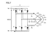
- FIG. 7 is a circuit diagram showing a current actually flowing through the inverter 4 shown in FIG.
- the synchronous machine 21 includes three-phase inductances 21r, 21s, and 21t.
- FIGS. 8A to 8C are time charts schematically showing actual commutation operation of the inverter 4, and are compared with FIGS. 4A to 4C.
- FIG. 8A shows the three-phase AC voltages VR, VS, and VT
- FIG. 8B shows the thyristor that is conductive among the six thyristors U, V, W, X, Y, and Z of the inverter 4.
- FIG. 8C shows the DC voltage VDC2 appearing between the input terminals 4a and 4b of the inverter 4. As shown in FIGS.
- FIGS. 9A and 9B are time charts schematically showing the actual commutation operation of the inverter 4 when the rotational speed N increases, and are compared with FIGS. 8A to 8C.
- FIG. 9A shows the three-phase AC voltages VR, VS, and VT
- FIG. 9B shows the DC voltage VDC2 that appears between the input terminals 4a and 4b of the inverter 4.
- FIGS. 9A and 9B when the rotational speed N increases, the rate at which the DC voltage VDC2 increases during commutation increases.
- FIGS. 10A and 10B are diagrams showing an actual relationship among the rotational speed N, the phase control angle ⁇ , and the DC voltage VDC2 in the constant ⁇ control method.
- FIG. 10B shows the relationship between the rotational speed N and the phase control angle ⁇ .
- the DC voltage VDC2 gradually increases as the rotational speed N increases due to the increase in the commutation overlap period. To increase. Since it is necessary to supply the DC voltage VDC1 higher than the DC voltage VDC2 from the converter 2, a large converter 2 is required.
- a method of increasing the phase control angle ⁇ linearly from the minimum value to the maximum value at a constant increase rate ⁇ / ⁇ N as the rotational speed N increases can be considered.
- this method is referred to as a ⁇ linear control method.
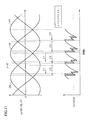
- FIGS. 11A and 11B are time charts schematically showing the actual commutation operation of the inverter 4 when the phase control angle ⁇ is increased, and are compared with FIGS. 8A to 8C.
- FIG. 11A shows the three-phase AC voltages VR, VS, and VT
- FIG. 11B shows the DC voltage VDC2 that appears between the input terminals 4a and 4b of the inverter 4.
- FIGS. 11A and 11B even if the phase control angle ⁇ is increased to ⁇ 1, ⁇ 2, ⁇ 3,... (Where ⁇ 1 ⁇ 2 ⁇ 3), it is caused by the commutation overlap angle u. As a result, the DC voltage VDC2 increases.
- the phase control angle ⁇ is increased, the DC voltage VDC2 is reduced by the amount corresponding to the hatched portion compared to the case where the phase control angle ⁇ is not increased. Therefore, the increase in the DC voltage VDC2 accompanying the increase in the rotational speed N can be corrected by the ⁇ linear control method.
- FIG. 12A is a diagram showing the relationship between the rotational speed N and the DC voltage VDC2 in the ⁇ linear control system
- FIG. 12B is a diagram showing the relationship between the rotational speed N and the phase control angle ⁇ in the system. . 12A and 12B, in the ⁇ linear control method, the phase control angle ⁇ is maintained at the minimum value ⁇ a when the rotational speed N is between 0 and Na.
- the inverter 4 is controlled based on the rotor position signal output from (not shown).
- the phase control angle ⁇ is maintained at a sufficiently small constant value ⁇ a regardless of the rotational speed N.
- the rotational speed N is between Na and Nb
- the phase control angle ⁇ increases linearly according to the rotational speed N from the minimum value ⁇ a to the maximum value ⁇ b.
- the rotational speed N exceeds Nb, the phase control angle ⁇ is maintained at the maximum value ⁇ b.
- the rotational speed N reaches Nb, the start of the synchronous machine 21 by the thyristor starter is finished, and the synchronous machine 21 is rotationally driven by the gas turbine.
- the DC voltage VDC2 increases linearly.
- the rotational speed N is between Na and Nb
- the DC voltage VDC2 has a peak value at a certain rotational speed Np.
- the rotational speed N exceeds Nb
- the DC voltage VDC2 increases according to the rotational speed N.
- the DC voltage VDC2 cannot be reduced uniformly over the entire rotation speed N, and the DC voltage VDC2 changes non-linearly at a certain rotation speed Np. Has a peak value. Therefore, it is necessary to provide a converter 2 having a capacity capable of outputting the DC voltage VDC1 even when the DC voltage VDC2 reaches a peak value. Further, such a converter 2 needs to be operated at a rotational speed N other than the rotational speed Np at which the direct-current voltage VDC2 has a peak value, so that the use efficiency of the converter 2 is reduced.
- the increase rate ⁇ / ⁇ N of the phase control angle ⁇ is changed twice or more according to the rotational speed N so that the DC voltage VDC2 approaches a constant value.
- the rotational speed N exceeds Nb, the phase control angle ⁇ is maintained at the maximum value ⁇ b.
- the DC voltage VDC2 increases linearly.
- the rotational speed N is between Na and Nm
- the DC voltage VDC2 has a peak value at a certain rotational speed Np1.
- the rotational speed N is between Nm and Nb
- the DC voltage VDC2 has a peak value at a certain rotational speed Np2.
- the rotational speed N exceeds Nb, the DC voltage VDC2 increases according to the rotational speed N.
- the ⁇ variable control method reduces the DC voltage VDC2 in the entire rotation speed N range. It can be seen that the DC voltage VDC2 can be made close to a constant value. In this way, the DC voltage VDC2 can be brought close to a constant value by increasing the number of times of changing the increase rate ⁇ / ⁇ N of the phase control angle ⁇ according to the rotational speed N to 3, 4, and 5. It becomes.
- the DC voltage VDC2 can be brought close to a constant value. Therefore, it is possible to reduce the size of the converter 2 and improve the utilization efficiency.
- the synchronous machine 21 is a generator driven by a gas turbine in a thermal power plant.
- the present invention is not limited to this, and the synchronous machine 21 is used in the general industrial field. It may be a synchronous machine.
- the synchronous machine 21 may be a synchronous machine for a cooling blower in an ironworks.
Landscapes
- Engineering & Computer Science (AREA)
- Power Engineering (AREA)
- Control Of Eletrric Generators (AREA)
- Inverter Devices (AREA)
- Control Of Ac Motors In General (AREA)
Description
この発明はサイリスタ起動装置に関し、特に、同期機を起動させるサイリスタ起動装置に関する。
サイリスタ起動装置は、三相交流電力を直流電力に変換するコンバータと、直流電力を平滑化させる直流リアクトルと、コンバータから直流リアクトルを介して与えられた直流電力を所望の周波数の三相交流電力に変換して同期機に与えるインバータとを備える。同期機に与える三相交流電力を制御することにより、停止状態の同期機を起動させて所定の回転速度で回転駆動させることができる。
インバータの制御方法としては、位相制御角を一定値に設定する第1の方法や、同期機の回転速度に応じて位相制御角を最小値から最大値まで一定の増加率で増大させる第2の方法がある(たとえば、特開2003-61380号公報(特許文献1)参照)。
しかし、従来の第1の方法では、同期機の回転速度が増大するに従って、インバータの入力端子側に現れる直流電圧が上昇するという問題がある。コンバータはインバータの入力端子側に現れる直流電圧よりも高い直流電圧を供給する必要があるので、第1の方法では、大型のコンバータが必要になる。
また、従来の第2の方法では、同期機の回転速度がある値になると、インバータの入力端子側に現れる直流電圧がピーク値になる。この場合は、直流電圧がピーク値になったときに直流電力を供給できる容量のコンバータを搭載し、直流電圧がピーク値にならない期間ではコンバータの出力を低下させる必要があり、コンバータの利用効率が低下する。
それゆえに、この発明の主たる目的は、コンバータの小型化と利用効率の向上を図ることが可能なサイリスタ起動装置を提供することである。
この発明に係るサイリスタ起動装置は、同期機を起動させるサイリスタ起動装置であって、第1の交流電力を直流電力に変換するコンバータと、直流電力を可変周波数の第2の交流電力に変換して同期機に供給するインバータと、同期機の回転速度を求める速度演算部と、同期機の回転速度とインバータの位相制御角との関係を示す関数またはテーブルを含み、速度演算部によって求められた同期機の回転速度に応じた値の位相制御角を求める制御角演算部と、制御角演算部によって求められた位相制御角に基づいてインバータを制御する制御部とを備えたものである。ここで、位相制御角は、同期機の回転速度に応じて最小値から最大値まで変化し、同期機の回転速度に対する位相制御角の増加率は、同期機の回転速度に応じて複数段階で変更される。
好ましくは、同期機の回転速度に対する位相制御角の増加率は、同期機の回転速度が変化してもインバータの入力端子に現れる直流電圧が一定になるように、同期機の回転速度に応じて複数段階で変更される。
また好ましくは、同期機の回転速度に対する位相制御角の増加率は、同期機の回転速度に応じて複数段階で減少する。
また好ましくは、同期機から出力される三相交流電圧を検出する電圧検出器を備え、速度演算部は、電圧検出器によって検出された三相交流電圧に基づいて同期機の回転速度を求める。
また好ましくは、同期機の回転子位置を検出する位置検出器を備え、速度演算部は、位置検出器の検出結果に基づいて同期機の回転速度を求める。
また好ましくは、同期機は火力発電所の発電機である。
この発明に係るサイリスタ起動装置では、インバータの位相制御角は、同期機の回転速度に応じて最小値から最大値まで変化し、同期機の回転速度に対する位相制御角の増加率は、同期機の回転速度に応じて複数段階で変更される。したがって、インバータの入力端子側に現れる直流電圧の変化を小さく抑制することができ、コンバータの小型化と利用効率の向上を図ることができる。
火力発電所では、同期機である発電機がガスタービンに結合されており、発電機はガスタービンによって回転駆動される。サイリスタ起動装置は、停止している発電機をガスタービンが自立昇速できる所定の回転速度まで回転させることにより、停止している発電機およびガスタービンを起動させる装置である。サイリスタ起動装置は、一般には負荷転流型インバータ(LCI:Load Commutated Inverter)と呼ばれている。
本発明の一実施の形態によるサイリスタ起動装置は、図1に示すように、変圧器1、コンバータ2、直流リアクトル3、およびインバータ4を備える。変圧器1は、交流電源20から供給される三相交流電圧を所定の電圧値の三相交流電圧に変換してコンバータ2に与える。
コンバータ2は、少なくとも6個のサイリスタを含む三相全波整流回路であり、変圧器1からの三相交流電力を可変電圧の直流電力に変換する。直流リアクトル3は、コンバータ2の正側出力端子2aとインバータ4の正側入力端子4aとの間に接続され、直流電流を平滑化する。コンバータ2の負側出力端子2bとインバータ4の負側入力端子4bとは互いに接続される。なお、もう1つの直流リアクトル3が、コンバータ2の負側出力端子2bとインバータ4の負側入力端子4bとの間に接続されていてもよい。
インバータ4の3つの出力端子4c~4eは、それぞれ同期機21のR相端子21a、S相端子21b、およびT相端子21cに接続される。インバータ4は、少なくとも6個のサイリスタを含む三相全波整流回路であり、コンバータ2から直流リアクトル3を介して供給される直流電力を可変周波数、可変電圧の三相交流電力に変換して同期機(発電機)21の固定子に与える。
また、このサイリスタ起動装置は、電圧検出器5,7、電流検出器6、速度演算部8、制御角演算部9、および制御部10を備える。電圧検出器5は、交流電源20から供給される三相交流電圧の瞬時値を検出し、検出値を示す信号を制御部10に与える。電流検出器6は、変圧器1からコンバータ2に流れる電流を検出し、検出値を示す信号を制御部10に与える。電圧検出器7は、同期機21のR相端子21a、S相端子21b、T相端子21cに現れる三相交流電圧VR,VS,VTの瞬時値を検出し、検出値を示す信号を制御部10および速度演算部8に与える。速度演算部8は、電圧検出器7からの信号に基づいて同期機21の回転速度N(rpm)を演算し、その演算値を示す信号を制御角演算部9および制御部10に与える。なお、電圧検出器7の代わりに同期機21の回転子の位置を検出する位置検出器を設け、速度演算部8において位置検出器の検出結果に基づいて同期機21の回転速度N(rpm)を演算しても構わない。
制御角演算部9は、同期機21の回転速度Nとインバータ4の位相制御角γとの関係を示す関数(またはテーブル)を記憶しており、その関数(またはテーブル)と速度演算部8から与えられた回転速度Nを示す信号とに基づいて、回転速度Nに応じた値の位相制御角γを求め、その位相制御角γを示す信号を制御部10に与える。
本願のサイリスタ起動装置では、回転速度Nが増大するに従って位相制御角γは最小値から最大値まで連続的に増加し、位相制御角γの変化率Δγ/ΔNは2回以上変化する。これにより、コンバータ2の小型化と利用効率の向上を図ることが可能となっている。これについては、後で詳細に説明する。
制御部10は、電圧検出器5、電流検出器6、および速度演算部8からの信号に基づいてコンバータ2を制御する。また、制御部10は、電圧検出器7(または上記位置検出器)、速度演算部8、および制御角演算部9からの信号に基づいてインバータ4を制御する。
次に、このサイリスタ起動装置の特徴となる位相制御角γの制御方法について詳細に説明する。起動時は図2に示すように、同期機21の端子電圧の実効値VEは、界磁の制御により回転速度N(rpm)が変わっても一定の定格電圧Vcに保たれる。コンバータ2は、起動中常に、インバータ4の入力端子側の直流電圧VDC2よりも直流リアクトル3の抵抗成分による電圧降下分だけ少し大きくなるように出力電圧VDC1を制御する。これにより、直流リアクトル3に流れる直流電流が制御される。
なお、同期機21を完全な停止状態から所定の回転速度Naで回転させるまでの間は、位相制御角γは回転速度Nに関係なく、十分小さな一定値に維持され、同期機21の端子電圧の実効値VEは0Vから定格電圧VCまで線形に増大する。
同期機21が回転駆動されると、同期機21のR相端子21a、S相端子21b、およびT相端子21cにそれぞれ三相交流電圧VR,VS,VTが現れる。この三相交流電圧VR,VS,VTは、インバータ4により直流電圧VDC2に変換されてインバータ4の入力端子4a,4b間に現れる。すなわち、インバータ4は、図3に示すように、少なくとも6個のサイリスタU,V,W,X,Y,Zを含む。
サイリスタU,V,Wのアノードはともに正側入力端子4aに接続され、それらのカソードはそれぞれ出力端子4c~4eに接続される。サイリスタX,Y,Zのアノードはそれぞれ出力端子4c~4eに接続され、それらのカソードはともに負側入力端子4bに接続される。
三相交流電圧VR,VS,VTに同期して、サイリスタU,V,Wのうちの1つのサイリスタと、サイリスタX,Y,Zのうちの1つのサイリスタとを導通させることにより、同期機21に三相交流電力を供給して同期機21の回転速度Nを上昇させることが可能となっている。
たとえば、図3に示すように、サイリスタU,Zが導通している場合は、同期機21のR相端子21aの電圧VRがサイリスタUを介してインバータ4の入力端子4aに現れ、T相端子21cの電圧VTがインバータ4の入力端子4bに現れる。すなわち、同期機21のR-T線間電圧VRT=VR-VTが直流電圧VDC2となって入力端子4a,4b間に現れる。
図4(a)~(c)は、インバータ4の理想的な転流動作を模式的に示すタイムチャートである。図4(a)は三相交流電圧VR,VS,VTを示し、図4(b)はインバータ4の6個のサイリスタU,V,W,X,Y,Zのうちの導通しているサイリスタを示し、図4(c)はインバータ4の入力端子4a,4b間に現れる直流電圧VDC2を示している。
図4(a)~(c)において、線間電圧VR-VS,VS-VT,VT-VRが0Vとなる点が位相制御角γの基準点であり、基準点ではγ=0度である。基準点から所望の角度γ1だけ位相を進めた時刻で所定のサイリスタに点弧指令信号を与える。たとえば、サイリスタUが導通している期間中にサイリスタVに点弧指令信号を与え、次にサイリスタVが導通している期間中にサイリスタWに点弧指令信号を与える。同様に、サイリスタZが導通している期間中にサイリスタXに点弧指令信号を与え、次にサイリスタXが導通している期間中にサイリスタYに点弧指令信号を与える。
導通するサイリスタの遷移に応じて、同期機21の線間電圧VR-VS,VS-VT,VT-VRがインバータ4の入力端子4a,4b間に直流電圧VDC2として順次現れる。制御部10は、同期機21の回転に応じて、6個のサイリスタU,V,W,X,Y,Zを2個ずつ順序良く点弧させて同期機21内を流れる電流の経路を制御し、同期機21の回転に同期する。
同期機21のインダクタンスが無視できるほど小さい理想的な場合は、位相制御角γを一定値に保っていれば、図4(c)に示すように、同期機21の3相の線間電圧VR-VS,VS-VT,VT-VRがインバータ4の入力端子4a,4b間に順次現れ続ける。入力端子4a,4b間の直流電圧VDC2の脈動分は直流リアクトル3によって平滑化され、直流電圧VDC2の平均値は一定になる。
また、図5(a)(b)は、回転速度Nが上昇した場合におけるインバータ4の理想的な転流動作を模式的に示すタイムチャートであって、図4(a)~(c)と対比される図である。図5(a)は三相交流電圧VR,VS,VTを示し、図5(b)はインバータ4の入力端子4a,4b間に現れる直流電圧VDC2を示している。図5(a)(b)に示すように、同期機21の回転速度Nが上昇した場合でも図4(a)~(c)と同様であり、直流電圧VDC2の平均値は変わらない。
また、図6(a)は理想的な場合における回転速度Nと直流電圧VDC2の関係を示す図であり、図6(b)はその場合における回転速度Nと位相制御角γの関係を示す図である。図6(a)(b)に示すように、理想的な場合は、回転速度Nの変化に関わらず位相制御角γを一定値に設定することにより、直流電圧VDC2は一定値に維持される。ここでは、位相制御角γを一定値に設定する方法をγ一定制御方式と称する。
しかし、実際には、導通していたサイリスタが瞬時に消弧することはない。同期機21などのインダクタンス成分に起因して、有限の期間、直前まで導通しているサイリスタとこれから導通するサイリスタの両方が導通状態になる期間が生じる。この期間は転流重なり期間と呼ばれ、転流重なり期間に対応する角度は転流重なり角uと呼ばれる。
図7は、図3に示したインバータ4に実際に流れる電流を示す回路図である。図7において、同期機21は3相のインダクタンス21r,21s,21tを含む。たとえば、サイリスタUが導通しているときにサイリスタVに点弧指令信号を与えても、インダクタンス21r,21sの影響により、転流重なり期間中は両方のサイリスタU,Vが導通し続ける。このため、インバータ4の入力端子4a,4b間の直流電圧VDC2は、R相電圧VRとS相電圧VSの平均値(VR+VS)/2からT相電圧VTを減算した電圧となる。すなわち、VDC2=-VT+(VR+VS)/2である。
図8(a)~(c)は、インバータ4の実際の転流動作を模式的に示すタイムチャートであって、図4(a)~(c)と対比される図である。図8(a)は三相交流電圧VR,VS,VTを示し、図8(b)はインバータ4の6個のサイリスタU,V,W,X,Y,Zのうちの導通しているサイリスタを示し、図8(c)はインバータ4の入力端子4a,4b間に現れる直流電圧VDC2を示している。図8(a)~(c)に示すように、転流重なり角uを考慮すると、転流重なり期間中は直流電圧VDC2が理想的な転流動作時と比較して、図中の斜線を施した分だけ大きくなる。
また、図9(a)(b)は、回転速度Nが上昇した場合におけるインバータ4の実際の転流動作を模式的に示すタイムチャートであって、図8(a)~(c)と対比される図である。図9(a)は三相交流電圧VR,VS,VTを示し、図9(b)はインバータ4の入力端子4a,4b間に現れる直流電圧VDC2を示している。図9(a)(b)に示すように、回転速度Nが上昇すると、転流時に直流電圧VDC2が上昇する割合が増加する。
また、図10(a)(b)はγ一定制御方式における回転速度Nと位相制御角γと直流電圧VDC2の実際の関係を示す図であり、特に、図10(a)は回転速度Nと直流電圧VDC2の関係を示し、図10(b)は回転速度Nと位相制御角γの関係を示している。図10(a)(b)に示すように、実際に位相制御角γを一定に維持すると、転流重なり期間における上昇分の影響により、回転速度Nの上昇に応じて直流電圧VDC2が徐々に増加する。その直流電圧VDC2よりも高い直流電圧VDC1をコンバータ2から供給する必要があるので、大型のコンバータ2が必要になる。
その対策として、回転速度Nの増加に応じて、位相制御角γを最小値から最大値まで一定の増加率Δγ/ΔNで線形に増大させる方法が考えられる。ここでは、この方法をγ線形制御方式と称する。
図11(a)(b)は、位相制御角γを増大させた場合におけるインバータ4の実際の転流動作を模式的に示すタイムチャートであって、図8(a)~(c)と対比される図である。図11(a)は三相交流電圧VR,VS,VTを示し、図11(b)はインバータ4の入力端子4a,4b間に現れる直流電圧VDC2を示している。図11(a)(b)に示すように、位相制御角γをγ1,γ2,γ3,…(ただし、γ1<γ2<γ3である)と増大させても、転流重なり角uに起因して直流電圧VDC2は増大する。しかし、位相制御角γを増大させると、位相制御角γを増大させない場合に比べて、斜線を施した部分の分だけ直流電圧VDC2が減少する。したがって、γ線形制御方式により、回転速度Nの増加に伴う直流電圧VDC2の上昇分を補正することができる。
図12(a)はγ線形制御方式における回転速度Nと直流電圧VDC2の関係を示す図であり、図12(b)は同方式における回転速度Nと位相制御角γの関係を示す図である。図12(a)(b)において、γ線形制御方式では、回転速度Nが0からNaの間では位相制御角γは最小値γaに維持される。
図2でも説明したが、同期機21を完全な停止状態から所定の回転速度Naで回転させるまでの間は、電圧検出器7の出力信号、または同期機21に設けられた回転子位置検出器(図示せず)から出力される回転子位置信号に基づいてインバータ4を制御する。この期間では、位相制御角γは回転速度Nに関係なく、十分小さな一定値γaに維持される。回転速度NがNaからNbの間では、位相制御角γは最小値γaから最大値γbまで回転速度Nに応じて線形に増大する。回転速度NがNbを超えると、位相制御角γは最大値γbに維持される。回転速度NがNbに到達すると、サイリスタ起動装置による同期機21の起動は終了し、同期機21はガスタービンによって回転駆動される。
また、回転速度Nが0からNaの間では、直流電圧VDC2は線形に増大する。回転速度NがNaからNbの間では、直流電圧VDC2は、ある回転速度Npにおいてピーク値を持つ。回転速度NがNbを超えると、直流電圧VDC2は回転速度Nに応じて増大する。
図12(a)(b)に示すようにγ線形制御方式では、回転速度Nの全域において満遍なく直流電圧VDC2を減少させることはできず、直流電圧VDC2は非線形に変化し、ある回転速度Npにおいてピーク値を持つ。したがって、直流電圧VDC2がピーク値になったときでも直流電圧VDC1を出力できるような容量のコンバータ2を設ける必要がある。また、そのようなコンバータ2は、直流電圧VDC2がピーク値となる回転速度Np以外の回転速度Nでは、直流電圧VDC1を下げて運転する必要があり、コンバータ2の利用効率が低下する。
そこで、本願発明では、直流電圧VDC2が一定値に近づくように、回転速度Nに応じて位相制御角γの増加率Δγ/ΔNを2回以上変化させる。ここでは、この方法をγ可変制御方式と称する。図13(a)(b)では、γの増加率Δγ/ΔNを2段階で変更している。すなわち、回転速度Nが0からNaの間では位相制御角γは最小値γaに維持される。回転速度NがNaからNmの間では、位相制御角γは最小値γaから所定値γmまで回転速度Nに応じて所定の増加率Δγ/ΔN=A1で線形に増大する。回転速度NがNmからNbの間では、位相制御角γは所定値γmから最大値γbまで回転速度Nに応じて所定の増加率Δγ/ΔN=A2で線形に増大する。回転速度NがNbを超えると、位相制御角γは最大値γbに維持される。ただし、Na<Nm<Nb、γa<γm<γb、A1>A2である。
また、回転速度Nが0からNaの間では、直流電圧VDC2は線形に増大する。回転速度NがNaからNmの間では、直流電圧VDC2は、ある回転速度Np1においてピーク値を持つ。回転速度NがNmからNbの間では、直流電圧VDC2は、ある回転速度Np2においてピーク値を持つ。回転速度NがNbを超えると、直流電圧VDC2は回転速度Nに応じて増大する。
図12(a)(b)のγ線形制御方式と図13(a)(b)のγ可変制御方式を比較すると、γ可変制御方式の方が回転速度Nの全域において直流電圧VDC2を減少させることができ、直流電圧VDC2を一定値に近づけることが可能であることが分かる。このようにして、回転速度Nに応じて位相制御角γの増加率Δγ/ΔNを変化させる回数を3回、4回、5回と増やすことにより、直流電圧VDC2を一定値に近付けることが可能となる。
この実施の形態では、回転速度Nに応じて位相制御角γの増加率Δγ/ΔNを複数回変化させるので、直流電圧VDC2を一定値に近付けることができる。したがって、コンバータ2の小型化と利用効率の向上を図ることができる。
なお、この実施の形態では、同期機21が火力発電所においてガスタービンにによって回転駆動される発電機である場合について説明したが、これに限るものではなく、同期機21は一般産業分野で使用される同期機であってもよい。たとえば、同期機21は、製鉄所の冷却ブロワ用の同期機であってもよい。
今回開示された実施の形態はすべての点で例示であって制限的なものではないと考えられるべきである。本発明の範囲は上記した説明でなくて請求の範囲によって示され、請求の範囲と均等の意味および範囲内でのすべての変更が含まれることが意図される。
1 変圧器、2 コンバータ、3 直流リアクトル、4 インバータ、5,7 電圧検出器、6 電流検出器、8 速度演算部、9 制御角演算部、10 制御部、20 交流電源、21 同期機。
Claims (6)
- 同期機(21)を起動させるサイリスタ起動装置であって、
第1の交流電力を直流電力に変換するコンバータ(2)と、
前記直流電力を可変周波数の第2の交流電力に変換して前記同期機(21)に供給するインバータ(4)と、
前記同期機(21)の回転速度を求める速度演算部(8)と、
前記同期機(21)の回転速度と前記インバータ(4)の位相制御角との関係を示す関数またはテーブルを含み、前記速度演算部(8)によって求められた前記同期機(21)の回転速度に応じた値の位相制御角を求める制御角演算部(9)と、
前記制御角演算部(9)によって求められた位相制御角に基づいて前記インバータ(4)を制御する制御部(10)とを備え、
前記位相制御角は、前記同期機(21)の回転速度に応じて最小値から最大値まで変化し、
前記同期機(21)の回転速度に対する前記位相制御角の増加率は、前記同期機(21)の回転速度に応じて複数段階で変更される、サイリスタ起動装置。 - 前記同期機(21)の回転速度に対する前記位相制御角の増加率は、前記同期機(21)の回転速度が変化しても前記インバータ(4)の入力端子に現れる直流電圧が一定になるように、前記同期機(21)の回転速度に応じて複数段階で変更される、請求項1に記載のサイリスタ起動装置。
- 前記同期機(21)の回転速度に対する前記位相制御角の増加率は、前記同期機(21)の回転速度に応じて複数段階で減少する、請求項1に記載のサイリスタ起動装置。
- 前記同期機(21)から出力される三相交流電圧を検出する電圧検出器(7)を備え、
前記速度演算部(8)は、前記電圧検出器(7)によって検出された三相交流電圧に基づいて前記同期機(21)の回転速度を求める、請求項1に記載のサイリスタ起動装置。 - 前記同期機(21)の回転子位置を検出する位置検出器を備え、
前記速度演算部(8)は、前記位置検出器の検出結果に基づいて前記同期機(21)の回転速度を求める、請求項1に記載のサイリスタ起動装置。 - 前記同期機(21)は火力発電所の発電機である、請求項1に記載のサイリスタ起動装置。
Priority Applications (4)
| Application Number | Priority Date | Filing Date | Title |
|---|---|---|---|
| US14/422,520 US20150236622A1 (en) | 2012-08-29 | 2012-08-29 | Thyristor starter |
| PCT/JP2012/071792 WO2014033849A1 (ja) | 2012-08-29 | 2012-08-29 | サイリスタ起動装置 |
| EP12883614.5A EP2892149B1 (en) | 2012-08-29 | 2012-08-29 | Thyristor activation device |
| JP2014532626A JP5918371B2 (ja) | 2012-08-29 | 2012-08-29 | サイリスタ起動装置 |
Applications Claiming Priority (1)
| Application Number | Priority Date | Filing Date | Title |
|---|---|---|---|
| PCT/JP2012/071792 WO2014033849A1 (ja) | 2012-08-29 | 2012-08-29 | サイリスタ起動装置 |
Publications (1)
| Publication Number | Publication Date |
|---|---|
| WO2014033849A1 true WO2014033849A1 (ja) | 2014-03-06 |
Family
ID=50182699
Family Applications (1)
| Application Number | Title | Priority Date | Filing Date |
|---|---|---|---|
| PCT/JP2012/071792 Ceased WO2014033849A1 (ja) | 2012-08-29 | 2012-08-29 | サイリスタ起動装置 |
Country Status (4)
| Country | Link |
|---|---|
| US (1) | US20150236622A1 (ja) |
| EP (1) | EP2892149B1 (ja) |
| JP (1) | JP5918371B2 (ja) |
| WO (1) | WO2014033849A1 (ja) |
Cited By (8)
| Publication number | Priority date | Publication date | Assignee | Title |
|---|---|---|---|---|
| WO2018235190A1 (ja) | 2017-06-21 | 2018-12-27 | 東芝三菱電機産業システム株式会社 | サイリスタ起動装置 |
| WO2018235189A1 (ja) | 2017-06-21 | 2018-12-27 | 東芝三菱電機産業システム株式会社 | サイリスタ起動装置 |
| WO2018235187A1 (ja) | 2017-06-21 | 2018-12-27 | 東芝三菱電機産業システム株式会社 | サイリスタ起動装置 |
| WO2018235188A1 (ja) | 2017-06-21 | 2018-12-27 | 東芝三菱電機産業システム株式会社 | サイリスタ起動装置 |
| WO2019159346A1 (ja) | 2018-02-19 | 2019-08-22 | 東芝三菱電機産業システム株式会社 | サイリスタ起動装置 |
| WO2020141569A1 (ja) | 2019-01-04 | 2020-07-09 | 東芝三菱電機産業システム株式会社 | サイリスタ起動装置 |
| WO2023084766A1 (ja) | 2021-11-15 | 2023-05-19 | 東芝三菱電機産業システム株式会社 | サイリスタ起動装置 |
| JPWO2024150292A1 (ja) * | 2023-01-11 | 2024-07-18 |
Citations (5)
| Publication number | Priority date | Publication date | Assignee | Title |
|---|---|---|---|---|
| JPS51129614A (en) * | 1975-05-06 | 1976-11-11 | Hitachi Ltd | Speed controller for no-commutator motor |
| JPH09322599A (ja) * | 1996-06-03 | 1997-12-12 | Hitachi Ltd | サイリスタ起動装置を備えた発電装置 |
| JP2003033070A (ja) * | 2001-06-29 | 2003-01-31 | Lg Electronics Inc | モータの運転を制御する装置及びその方法 |
| JP2003061380A (ja) | 2001-08-10 | 2003-02-28 | Toshiba Corp | 同期機のサイリスタ起動装置 |
| JP2012135067A (ja) * | 2010-12-20 | 2012-07-12 | Hitachi Appliances Inc | 電動機の駆動装置 |
Family Cites Families (10)
| Publication number | Priority date | Publication date | Assignee | Title |
|---|---|---|---|---|
| JPS5953795B2 (ja) * | 1978-02-03 | 1984-12-26 | 株式会社日立製作所 | サイリスタモ−タの制御装置 |
| US4654572A (en) * | 1984-05-04 | 1987-03-31 | Kabushiki Kaisha Toshiba | Load-commutated inverter for operating synchronous motor |
| US4870338A (en) * | 1988-09-26 | 1989-09-26 | Westinghouse Electric Corp. | Load commutated inverter (LCI) induction motor drive |
| JP3506457B2 (ja) * | 1993-04-23 | 2004-03-15 | 東芝キヤリア株式会社 | 空気調和機におけるコンプレッサの起動制御方法 |
| JP3052804B2 (ja) * | 1995-05-19 | 2000-06-19 | トヨタ自動車株式会社 | 原動機の始動装置および始動方法 |
| US6605912B1 (en) * | 1998-06-25 | 2003-08-12 | Delphi Technologies, Inc. | Method for controlling a permanent magnet motor |
| KR100645808B1 (ko) * | 2004-12-08 | 2006-11-23 | 엘지전자 주식회사 | 모터 제어방법 |
| US8519656B2 (en) * | 2008-10-01 | 2013-08-27 | Toshiba Mitsubishi-Electric Industrial Systems Corporation | Synchronous machine starting device |
| EP2384540B1 (en) * | 2009-01-30 | 2014-12-17 | Siemens Aktiengesellschaft | Power system frequency inertia for power generation system |
| WO2011024247A1 (ja) * | 2009-08-24 | 2011-03-03 | 東芝三菱電機産業システム株式会社 | 同期機起動装置 |
-
2012
- 2012-08-29 EP EP12883614.5A patent/EP2892149B1/en active Active
- 2012-08-29 JP JP2014532626A patent/JP5918371B2/ja active Active
- 2012-08-29 WO PCT/JP2012/071792 patent/WO2014033849A1/ja not_active Ceased
- 2012-08-29 US US14/422,520 patent/US20150236622A1/en not_active Abandoned
Patent Citations (5)
| Publication number | Priority date | Publication date | Assignee | Title |
|---|---|---|---|---|
| JPS51129614A (en) * | 1975-05-06 | 1976-11-11 | Hitachi Ltd | Speed controller for no-commutator motor |
| JPH09322599A (ja) * | 1996-06-03 | 1997-12-12 | Hitachi Ltd | サイリスタ起動装置を備えた発電装置 |
| JP2003033070A (ja) * | 2001-06-29 | 2003-01-31 | Lg Electronics Inc | モータの運転を制御する装置及びその方法 |
| JP2003061380A (ja) | 2001-08-10 | 2003-02-28 | Toshiba Corp | 同期機のサイリスタ起動装置 |
| JP2012135067A (ja) * | 2010-12-20 | 2012-07-12 | Hitachi Appliances Inc | 電動機の駆動装置 |
Cited By (29)
| Publication number | Priority date | Publication date | Assignee | Title |
|---|---|---|---|---|
| CN110771031B (zh) * | 2017-06-21 | 2022-12-23 | 东芝三菱电机产业系统株式会社 | 晶闸管起动装置 |
| JPWO2018235188A1 (ja) * | 2017-06-21 | 2020-05-21 | 東芝三菱電機産業システム株式会社 | サイリスタ起動装置 |
| WO2018235187A1 (ja) | 2017-06-21 | 2018-12-27 | 東芝三菱電機産業システム株式会社 | サイリスタ起動装置 |
| KR20200017490A (ko) | 2017-06-21 | 2020-02-18 | 도시바 미쓰비시덴키 산교시스템 가부시키가이샤 | 사이리스터 기동 장치 |
| US11211882B2 (en) | 2017-06-21 | 2021-12-28 | Toshiba Mitsubishi-Electric Industrial Systems Corporation | Thyristor starter |
| JPWO2018235187A1 (ja) * | 2017-06-21 | 2020-01-23 | 東芝三菱電機産業システム株式会社 | サイリスタ起動装置 |
| CN110771031A (zh) * | 2017-06-21 | 2020-02-07 | 东芝三菱电机产业系统株式会社 | 晶闸管起动装置 |
| KR20200017498A (ko) | 2017-06-21 | 2020-02-18 | 도시바 미쓰비시덴키 산교시스템 가부시키가이샤 | 사이리스터 기동 장치 |
| WO2018235189A1 (ja) | 2017-06-21 | 2018-12-27 | 東芝三菱電機産業システム株式会社 | サイリスタ起動装置 |
| KR20200017500A (ko) | 2017-06-21 | 2020-02-18 | 도시바 미쓰비시덴키 산교시스템 가부시키가이샤 | 사이리스터 기동 장치 |
| WO2018235188A1 (ja) | 2017-06-21 | 2018-12-27 | 東芝三菱電機産業システム株式会社 | サイリスタ起動装置 |
| JPWO2018235190A1 (ja) * | 2017-06-21 | 2020-05-28 | 東芝三菱電機産業システム株式会社 | サイリスタ起動装置 |
| US11233466B2 (en) | 2017-06-21 | 2022-01-25 | Toshiba Mitsubishi-Electric Industrial Systems Corporation | Thyristor starter |
| US10951144B2 (en) | 2017-06-21 | 2021-03-16 | Toshiba Mitsubishi-Electric Industrial Systems Corporation | Thyristor starter |
| WO2018235190A1 (ja) | 2017-06-21 | 2018-12-27 | 東芝三菱電機産業システム株式会社 | サイリスタ起動装置 |
| US11239769B2 (en) | 2017-06-21 | 2022-02-01 | Toshiba Mitsubishi-Electric Industrial Systems Corporation | Thyristor starter |
| US11469692B2 (en) | 2018-02-19 | 2022-10-11 | Toshiba Mitsubishi-Electric Industrial Systems Corporation | Thyristor starter |
| KR20200123200A (ko) | 2018-02-19 | 2020-10-28 | 도시바 미쓰비시덴키 산교시스템 가부시키가이샤 | 사이리스터 기동 장치 |
| WO2019159346A1 (ja) | 2018-02-19 | 2019-08-22 | 東芝三菱電機産業システム株式会社 | サイリスタ起動装置 |
| CN112292811A (zh) * | 2019-01-04 | 2021-01-29 | 东芝三菱电机产业系统株式会社 | 晶闸管起动装置 |
| KR20210019058A (ko) | 2019-01-04 | 2021-02-19 | 도시바 미쓰비시덴키 산교시스템 가부시키가이샤 | 사이리스터 기동 장치 |
| US11277087B2 (en) | 2019-01-04 | 2022-03-15 | Toshiba Mitsubishi-Electric Industrial Systems Corporation | Thyristor starter |
| JPWO2020141569A1 (ja) * | 2019-01-04 | 2021-02-18 | 東芝三菱電機産業システム株式会社 | サイリスタ起動装置 |
| WO2020141569A1 (ja) | 2019-01-04 | 2020-07-09 | 東芝三菱電機産業システム株式会社 | サイリスタ起動装置 |
| WO2023084766A1 (ja) | 2021-11-15 | 2023-05-19 | 東芝三菱電機産業システム株式会社 | サイリスタ起動装置 |
| KR20240099489A (ko) | 2021-11-15 | 2024-06-28 | 가부시키가이샤 티마이크 | 사이리스터 기동 장치 |
| JPWO2024150292A1 (ja) * | 2023-01-11 | 2024-07-18 | ||
| WO2024150292A1 (ja) * | 2023-01-11 | 2024-07-18 | 株式会社Tmeic | モータ駆動システムおよびインバータ装置の制御方法 |
| JP7696195B2 (ja) | 2023-01-11 | 2025-06-20 | 株式会社Tmeic | モータ駆動システムおよびインバータ装置の制御方法 |
Also Published As
| Publication number | Publication date |
|---|---|
| EP2892149A4 (en) | 2016-07-06 |
| JPWO2014033849A1 (ja) | 2016-08-08 |
| JP5918371B2 (ja) | 2016-05-18 |
| EP2892149A1 (en) | 2015-07-08 |
| US20150236622A1 (en) | 2015-08-20 |
| EP2892149B1 (en) | 2020-12-16 |
Similar Documents
| Publication | Publication Date | Title |
|---|---|---|
| JP5918371B2 (ja) | サイリスタ起動装置 | |
| CN108292902B (zh) | 用于变速感应电机系统的混合驱动电路和控制方法 | |
| US10050573B2 (en) | Wind power generation system including doubly-fed generator and stator-connected auxiliary converter | |
| JP3980005B2 (ja) | モータ駆動用インバータ制御装置および空気調和機 | |
| US20150365008A1 (en) | Power conversion device and control method therefor | |
| CN111066237A (zh) | 用于控制风能设施的多相他励同步发电机的方法 | |
| JP5168955B2 (ja) | 電動機制御装置 | |
| JP6704523B2 (ja) | サイリスタ起動装置 | |
| KR102554511B1 (ko) | 사이리스터 기동 장치 | |
| CN112292811B (zh) | 晶闸管起动装置 | |
| US11239769B2 (en) | Thyristor starter | |
| JP6044854B2 (ja) | 電動工具 | |
| JPWO2019159346A1 (ja) | サイリスタ起動装置 | |
| JP7315799B1 (ja) | サイリスタ起動装置 | |
| KR101861986B1 (ko) | 인버터 제어장치 | |
| Alcaso et al. | Asymmetrical operation of a twelve-pulse LCI drive system with power converter faults | |
| WO2018235190A1 (ja) | サイリスタ起動装置 | |
| JP2012005303A (ja) | 直流電源装置 |
Legal Events
| Date | Code | Title | Description |
|---|---|---|---|
| 121 | Ep: the epo has been informed by wipo that ep was designated in this application |
Ref document number: 12883614 Country of ref document: EP Kind code of ref document: A1 |
|
| ENP | Entry into the national phase |
Ref document number: 2014532626 Country of ref document: JP Kind code of ref document: A |
|
| WWE | Wipo information: entry into national phase |
Ref document number: 14422520 Country of ref document: US |
|
| NENP | Non-entry into the national phase |
Ref country code: DE |