WO2014033861A1 - 印刷機 - Google Patents
印刷機 Download PDFInfo
- Publication number
- WO2014033861A1 WO2014033861A1 PCT/JP2012/071880 JP2012071880W WO2014033861A1 WO 2014033861 A1 WO2014033861 A1 WO 2014033861A1 JP 2012071880 W JP2012071880 W JP 2012071880W WO 2014033861 A1 WO2014033861 A1 WO 2014033861A1
- Authority
- WO
- WIPO (PCT)
- Prior art keywords
- squeegee
- scooping
- solder
- mask
- scraping
- Prior art date
- Legal status (The legal status is an assumption and is not a legal conclusion. Google has not performed a legal analysis and makes no representation as to the accuracy of the status listed.)
- Ceased
Links
Images





Classifications
-
- B—PERFORMING OPERATIONS; TRANSPORTING
- B41—PRINTING; LINING MACHINES; TYPEWRITERS; STAMPS
- B41F—PRINTING MACHINES OR PRESSES
- B41F15/00—Screen printers
- B41F15/08—Machines
- B41F15/0881—Machines for printing on polyhedral articles
-
- B—PERFORMING OPERATIONS; TRANSPORTING
- B41—PRINTING; LINING MACHINES; TYPEWRITERS; STAMPS
- B41F—PRINTING MACHINES OR PRESSES
- B41F15/00—Screen printers
- B41F15/14—Details
- B41F15/40—Inking units
- B41F15/42—Inking units comprising squeegees or doctors
- B41F15/423—Driving means for reciprocating squeegees
-
- B—PERFORMING OPERATIONS; TRANSPORTING
- B41—PRINTING; LINING MACHINES; TYPEWRITERS; STAMPS
- B41F—PRINTING MACHINES OR PRESSES
- B41F15/00—Screen printers
- B41F15/14—Details
- B41F15/44—Squeegees or doctors
- B41F15/46—Squeegees or doctors with two or more operative parts
-
- H—ELECTRICITY
- H05—ELECTRIC TECHNIQUES NOT OTHERWISE PROVIDED FOR
- H05K—PRINTED CIRCUITS; CASINGS OR CONSTRUCTIONAL DETAILS OF ELECTRIC APPARATUS; MANUFACTURE OF ASSEMBLAGES OF ELECTRICAL COMPONENTS
- H05K3/00—Apparatus or processes for manufacturing printed circuits
- H05K3/10—Apparatus or processes for manufacturing printed circuits in which conductive material is applied to the insulating support in such a manner as to form the desired conductive pattern
- H05K3/12—Apparatus or processes for manufacturing printed circuits in which conductive material is applied to the insulating support in such a manner as to form the desired conductive pattern using thick film techniques, e.g. printing techniques to apply the conductive material or similar techniques for applying conductive paste or ink patterns
- H05K3/1216—Apparatus or processes for manufacturing printed circuits in which conductive material is applied to the insulating support in such a manner as to form the desired conductive pattern using thick film techniques, e.g. printing techniques to apply the conductive material or similar techniques for applying conductive paste or ink patterns by screen printing or stencil printing
- H05K3/1233—Methods or means for supplying the conductive material and for forcing it through the screen or stencil
-
- H—ELECTRICITY
- H05—ELECTRIC TECHNIQUES NOT OTHERWISE PROVIDED FOR
- H05K—PRINTED CIRCUITS; CASINGS OR CONSTRUCTIONAL DETAILS OF ELECTRIC APPARATUS; MANUFACTURE OF ASSEMBLAGES OF ELECTRICAL COMPONENTS
- H05K2203/00—Indexing scheme relating to apparatus or processes for manufacturing printed circuits covered by H05K3/00
- H05K2203/01—Tools for processing; Objects used during processing
- H05K2203/0104—Tools for processing; Objects used during processing for patterning or coating
- H05K2203/0139—Blade or squeegee, e.g. for screen printing or filling of holes
-
- H—ELECTRICITY
- H05—ELECTRIC TECHNIQUES NOT OTHERWISE PROVIDED FOR
- H05K—PRINTED CIRCUITS; CASINGS OR CONSTRUCTIONAL DETAILS OF ELECTRIC APPARATUS; MANUFACTURE OF ASSEMBLAGES OF ELECTRICAL COMPONENTS
- H05K3/00—Apparatus or processes for manufacturing printed circuits
- H05K3/30—Assembling printed circuits with electric components, e.g. with resistors
- H05K3/32—Assembling printed circuits with electric components, e.g. with resistors electrically connecting electric components or wires to printed circuits
- H05K3/34—Assembling printed circuits with electric components, e.g. with resistors electrically connecting electric components or wires to printed circuits by soldering
- H05K3/3465—Application of solder
- H05K3/3485—Application of solder paste, slurry or powder
Definitions
- the present invention relates to a printing machine for printing solder on a substrate.
- a printing machine for printing cream solder on the surface of a circuit board before electronic components are mounted has been used.
- a mask having a printing opening is arranged on the upper surface of the circuit board, paste-like cream solder is placed on the upper surface of the mask, and the cream solder is moved from one of the mask upper surfaces to the other with a squeegee.
- the cream solder is printed on the circuit board.
- the mask may be replaced depending on the type of circuit board. In this case, the cream solder remaining on the upper surface of the mask is transferred to the upper surface of a new mask using a spatula. Is done.
- the cream solder must be transferred in several steps with a spatula, which complicates the work and takes a long time.
- the shape of the cream solder collapses during transfer, it is necessary to prepare the shape of the cream solder when printing is started using a new mask.
- a printing machine having a solder collection squeegee that moves cream solder to a predetermined place while printing on a circuit board on a plurality of sets of rails has also been developed (see, for example, Japanese Patent Application Laid-Open No. 2008-109159). .
- This printing machine double track stencil printing device
- a wiper squeegee for moving cream solder includes a distribution squeegee that is arranged slightly above the wiper squeegee while moving in the moving direction, and moves with the wiper squeegee, and a frame that extends vertically
- a solder collecting squeegee arm is provided at the lower end of the member and includes a wiper squeegee and a solder collecting head similar to a shovel extending in the horizontal direction toward the distribution squeegee.
- the cream solder located between the wiper squeegee and the distribution squeegee can be placed on the solder collection head by moving the solder collection head toward the wiper squeegee while moving the cream solder with the wiper squeegee. Furthermore, by moving the solder collecting squeegee arm in this state, the solder can be conveyed to a predetermined position.
- the wiper squeegee is made of polyurethane and the distribution squeegee is made of Teflon (registered trademark). Since the paste-like cream solder has good wettability to such a material, it easily adheres to a wiper squeegee or a distribution squeegee. As a result, the solder adhering to the wiper squeegee or the distribution squeegee may droop within the printing operation range.
- the present invention has been made to address the above-described problems, and the purpose of the present invention is to reduce the set-up time and to allow the solder to adhere by loading and unloading all at once without destroying the shape of the solder. It is an object of the present invention to provide a printing machine having solder scraping means that can be prevented.
- a structural feature of the printing press according to the present invention is that a squeegee unit having a printing squeegee is moved forward and backward in one direction on the upper surface of a mask on which a substrate is disposed below to move solder. And a scraping squeegee that advances and retreats in the direction of the printing operation together with the squeegee unit, and a scooping squeegee that advances and retreats in the direction of the printing operation together with the squeegee unit.
- the scooping squeegee can be contacted and separated relative to the scooping squeegee so that the solder on the top surface of the mask can be scooped, and the surface of the scraping squeegee facing the scooping squeegee has uneven fibers or sponges. Is that it is attached.
- the printing press according to the present invention is configured such that the scraping squeegee and scooping squeegee advance and retreat together with the squeegee unit together with the printing squeegee.
- the scraping squeegee and the scooping squeegee can be brought into and out of contact with each other. For this reason, the solder brought to one side of the upper surface of the mask by the printing squeegee can be transferred at once by sandwiching between the scraping squeegee and the scooping squeegee.
- the solder can be transferred at a time, the time for transferring the solder at the time of mask replacement can be shortened. Further, since the transfer can be performed without destroying the shape of the solder, it becomes unnecessary to prepare the shape of the solder when a new mask is used, thereby reducing the time for solder rolling.
- one direction said by this invention is a direction including reciprocation, such as right and left and front and back.
- Another structural feature of the printing press according to the present invention is that a frame is provided on the outer periphery of the mask, so that the scraping squeegee and scooping squeegee can rise above the height of the mask frame. It is in.
- the scraping squeegee and scooping squeegee can be moved up and down between the upper surface of the mask and the upper part of the frame. For this reason, when replacing the mask, the scraping squeegee and scooping squeegee are raised above the frame, making it easy to replace the mask while retaining the solder on the scraping squeegee and scooping squeegee. It can be carried out.
- the scraping squeegee and scooping squeegee are raised above the frame to prevent the scraping squeegee and scooping squeegee from interfering with the printing operation. .
- Still another structural feature of the printing press according to the present invention is that the scraping squeegee and scooping squeegee can be moved up and down separately.
- the solder when scooping up the solder, the solder can be placed on the scooping squeegee using the surface of the scraping squeegee that faces the scooping squeegee. Further, when the solder is lowered, the solder can be removed from the scooping squeegee and supplied to the mask using a surface of the scraping squeegee opposite to the surface facing the scooping squeegee.
- Still another structural feature of the printing press according to the present invention is that uneven fibers or sponges are attached to the surface of the scraping squeegee opposite to the surface facing the scooping squeegee. According to the present invention, it is difficult for the solder to scrape off and adhere to the squeegee when the solder is supplied to the mask.
- a manual soldering device can be used in a conventional printing machine.
- the solder scooping tool in this case is a solder scooping tool for the operator to scoop the solder on the mask of the printing machine, and a scooping tool for scooping up the solder on the top surface of the mask.
- a scraper for placing the solder on the scooping device, and the surface of the scraping device can be configured such that uneven fibers or sponges are attached.
- the time for solder transfer can be shortened because the solder can be put on and removed from the mask all at once. Further, since the solder can be put down without breaking the shape of the solder, it is not necessary to prepare the shape of the solder in the next operation, thereby shortening the time for solder rolling. Further, since the solder is prevented from adhering to the scraper, the scraper can be reused efficiently. In addition, since a scooping device is what a solder is put on or taken down by a scraper, it is prevented by a scraper that solder adheres.
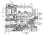
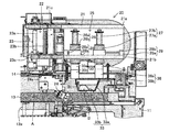
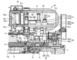
- FIG. 1 is a cross-sectional view of a printing machine according to an embodiment of the present invention. It is the side view which showed the scraping squeegee. It is sectional drawing which showed the principal part of the printing machine of the state which dropped the scraping squeegee and the scooping squeegee at intervals. It is sectional drawing which showed the principal part of the printing machine of the state which moved the scooping squeegee to the scraping squeegee side and scooped cream solder. It is sectional drawing which showed the principal part of the printing machine of the state which lifted cream solder with the scraping squeegee and the scooping squeegee.
- FIG. 1 shows a printing machine 10 according to the embodiment.
- the printing machine 10 is an apparatus for printing paste-like cream solder B on the surface of a printed board A.
- the printing machine 10 includes a base 11, an installation device 12 provided on the base 11 for installing the printed circuit board A at a predetermined installation position, and a mask installed so as to be replaceable above the installation position of the printed circuit board A. 13 and a squeegee unit 20 which is provided above the mask 13 and moves forward and backward in the X-axis direction (left-right direction in FIG. 1) by the operation of the driving device.
- the left and right, front and rear, and upper and lower directions will be described with reference to FIG.
- the base 11 is configured by providing leg portions 11b on both left and right sides of the main body 11a.
- the main body 11a is formed with a wide opening portion 11c penetrating in the front-rear direction and an opening portion penetrating vertically.
- a carry-in conveyor and a carry-out conveyor are respectively provided before and after the opening 11c, and the installation device 12 includes a carry-in conveyor, a carry-out conveyor, It is provided between.
- the printed circuit board A is conveyed to the setting device 12 by a carry-in conveyor, and after being subjected to printing processing, is carried out by a carry-out conveyor.
- the installation device 12 positions and fixes the printed circuit board A conveyed by the carry-in conveyor on the lower surface of the mask 13, and supports the printed circuit board A so that it can be displaced in the rotational direction on the left, right, front, back, top, bottom, and horizontal planes. To do.
- the installation apparatus 12 includes a support fixing unit 12a including a support mechanism that supports the printed circuit board A and a clamp mechanism that grips the printed circuit board A, and a moving mechanism that moves the support fixing unit 12a in each direction.
- the support mechanism of the support fixing portion 12a supports the printed circuit board A from below using a support pin, and the clamp mechanism sandwiches the printed circuit board A from the left and right with a pair of gripping pieces.
- the moving mechanism includes a guide rail 12b, a ball screw 12c, a servo motor 12d, and the like, and an X-axis drive unit that moves the support fixing unit 12a in the X-axis direction, and the support fixing unit 12a in the Y-axis direction (front-rear direction).
- a Y-axis drive unit that moves the support fixing unit 12a in the Z-axis direction (vertical direction), and an R-axis drive unit that rotates the support fixing unit 12a around the Z-axis.
- the mask 13 is configured by attaching a mask sheet having a plurality of printing openings to the lower end opening of a rectangular frame. This mask 13 is installed so as to close the opening that penetrates the top and bottom of the main body 11a of the base 11, and as shown in FIG. It is installed near the right end of 11a. Further, as the mask 13, a plurality of masks having different numbers and arrangements of printing openings are used, and can be appropriately replaced according to the printed board A to be printed.
- a linear guide 14 is provided that is positioned above the mask 13 so as to be spanned by a support portion provided at a distance from the left and right, and the squeegee unit 20 is attached to the linear guide 14. It is mounted movably.
- the squeegee unit 20 reciprocates in the left-right direction along the linear guide 14 by the operation of a drive device (not shown).
- the squeegee unit 20 is configured by assembling a squeegee head 22 and a solder lifting head 25 to a frame-like head support portion 21.
- the head support portion 21 is configured by connecting a plate-like upper surface portion 21a and a lower surface portion 21b arranged at intervals in the vertical direction via a connecting piece 21c or the like.
- a long and narrow elongated hole (not shown) extending in the left and right direction penetrates in a portion where the solder lifting head 25 is disposed on the lower surface portion 21b.
- the squeegee head 22 includes a lifting mechanism 23 including a ball screw 23a and a guide shaft 23b provided above and below the upper surface portion 21a and the lower surface portion 21b, and a squeegee holding mechanism that moves up and down via a connecting member 23c by the operation of the lifting mechanism 23.
- the printing squeegee 24 is attached to the squeegee holding part 24a.
- the printing squeegee 24 moves the cream solder B along the upper surface (mask sheet) of the mask 13 and is composed of an elongated member whose width in the front-rear direction is set slightly longer than the printed circuit board A.
- the front end portion in the direction is composed of a flat plate member.
- the plate member at the tip of the printing squeegee 24 is made of hard urethane or stainless steel, and when it comes into contact with the upper surface of the mask 13, there is no gap between the portions other than the printing opening. It is formed as follows. Further, the printing squeegee 24 is supported by the squeegee holding portion 24a via a support shaft, and is rotatable in the direction around the support shaft.
- the solder elevating head 25 is provided on the right side of the squeegee head 22 in the head support 21 and includes elevating cylinders 26 and 27, drive cylinders 28 and 29, a scraping squeegee 31, and a scooping squeegee 33.
- the elevating cylinder 26 includes a cylindrical cylinder body 26a that extends vertically and a shaft portion 26b that passes through the cylinder body 26a and moves up and down with respect to the cylinder body 26a.
- the cylinder body 26a is a lower surface portion 21b. It is located in the long hole.
- the elevating cylinder 27 includes a cylinder main body 27a and a shaft portion 27b, and the cylinder main body 27a is positioned in the long hole of the lower surface portion 21b.
- the drive cylinder 28 has a cylinder main body 28a fixed to the center portion on the upper surface of the lower surface portion 21b, and a ring-shaped holding portion that can move forward and backward in the right direction from the cylinder main body 28a and holds the cylinder main body 26a of the elevating cylinder 26 at the tip. It is comprised with the formed movement holding
- the drive cylinder 28 moves the lifting / lowering cylinder 26 left and right along the long hole of the lower surface portion 21b by moving the movement holding portion 28b forward and backward.
- the drive cylinder 29 is formed with a cylinder main body 29a fixed to the right end on the upper surface of the lower surface portion 21b, and a ring-shaped holding portion that can move forward and backward in the left direction from the cylinder main body 29a and holds the cylinder main body 27a of the elevating cylinder 27 at the tip. And the movable holding portion 29b.
- the drive cylinder 29 moves the elevating cylinder 27 left and right along the long hole of the lower surface portion 21b by moving the moving holding portion 29b forward and backward. For this reason, the raising / lowering cylinder 26 and the raising / lowering cylinder 27 can be advanced / retreated mutually along the long hole of the lower surface part 21b.
- the scraping squeegee 31 is detachably attached to the elevating cylinder 26 via an attachment jig 35
- the scooping squeegee 33 is detachably attached to the elevating cylinder 27 via an attachment jig 36.
- the attachment jig 35 is composed of an upper engagement portion 35a and a lower engagement portion 35b that can be attached to and detached from each other.
- the upper engagement portion 35a is attached to the lower end of the shaft portion 26b of the elevating cylinder 26, and the lower engagement portion 35a.
- the joint portion 35 b is attached to the upper end portion of the scraping squeegee 31.
- the attachment jig 36 includes an upper engagement portion 36 a and a lower engagement portion 36 b that are detachable from each other.
- the upper engagement portion 36 a is attached to the lower end of the shaft portion 27 b of the elevating cylinder 27.
- the lower engaging portion 36 b is attached to the upper end portion of the scooping squeegee 33.
- the scraping squeegee 31 and the scooping squeegee 33 are for transferring the cream solder B remaining on the mask 13 to the newly installed mask 13 when the mask 13 is replaced. 27 and the drive cylinders 28 and 29 are moved separately in the vertical and horizontal directions. As shown in FIG. 2, the scraping squeegee 31 is formed in a plate shape that is inclined so that the lower end is located on the right side of the upper end connected to the lower engaging portion 35b.
- the printing squeegee 24 is set to be substantially the same.
- the scraping squeegee 31 includes a main body 31a made of hard urethane or stainless steel, and a sheet-like covering portion 32 that covers both the left and right sides and the lower end of the main body 31a. Yes.
- the covering portion 32 is made of a nonwoven fabric having a surface with irregularities.
- the scooping squeegee 33 includes a vertical piece 33a connected to the lower engagement portion 36b and a horizontal piece 33b extending leftward from the lower end of the vertical piece 33a.
- the vertical piece 33a is formed in a plate shape inclined so that the lower end is located on the left side of the upper end, and the horizontal piece 33b extends horizontally from the lower end of the vertical piece 33a toward the lower end of the scraping squeegee 31. ing.
- the width of the scooping squeegee 33 in the front-rear direction is slightly longer than the width of the scraping squeegee 31 in the front-rear direction.
- the wall part (illustration) with a low height for preventing the cream solder B from spilling out is formed before and after the horizontal piece 33b.
- the scooping squeegee 33 is also made of hard urethane or stainless steel.
- the scooping squeegee 33 is for scooping up the cream solder B on the horizontal piece 33b.
- the scraping squeegee 31 moves the cream solder B on the mask 13 onto the horizontal piece 33b or on the horizontal piece 33b.
- the cream solder B is moved onto the mask 13.
- the cream solder B is printed on the surface of the printed circuit board A using the printing machine 10 configured as described above, first, the printed circuit board A conveyed from the carry-in conveyor is installed in the installation device 12. Position on the lower surface of the mask 13. Then, the lifting cylinders 26 and 27 are operated to raise the scraping squeegee 31 and the scooping squeegee 33 and lower the printing squeegee 24 to contact the upper surface of the mask 13 as shown in FIG. In this state, the cream solder B is placed on one of the upper surfaces of the mask 13. Then, the cream solder B is printed on the surface of the printed circuit board A in a predetermined shape by moving the squeegee unit 20 in the left-right direction. In this case, since the scraping squeegee 31 and the scooping squeegee 33 are positioned above the mask 13, the printing process by the printing squeegee 24 is not hindered.
- the printed circuit board A that has been printed is transported to the next step by the carry-out conveyor, and the new printed circuit board A transported from the carry-in conveyor is positioned on the lower surface of the mask 13.
- the cream solder B is printed on the surface of the printed board A, and the above-described processing is repeated.
- the mask 13 is replaced with one corresponding to the new printed circuit board A, and the remaining cream solder B is transferred from the mask 13 after use to the mask 13 before use.
- the cream solder B is brought close to the right side of the mask 13 by the printing squeegee 24 and the squeegee unit 20 is moved so that the solder lifting head 25 is moved above the cream solder B.
- the scraping squeegee 31 is positioned at the left end of the moving range
- the scooping squeegee 33 is positioned at the right end of the moving range.
- the elevating cylinders 26 and 27 are operated to lower the scraping squeegee 31 and the scooping squeegee 33 so that the lower portions thereof are in contact with the surface of the mask 13.
- the cream solder B is sandwiched between the lower end portion of the scraping squeegee 31 and the distal end portion of the horizontal piece 33b of the scooping squeegee 33.
- the drive cylinder 29 is operated to move the scooping squeegee 33 together with the lifting cylinder 27 in the left direction.
- the cream solder B is scooped up on the upper surface of the horizontal piece 33b of the scooping squeegee 33.
- the cream solder B is prevented from moving leftward by the scraping squeegee 31, and is smoothly pushed up to the upper surface of the horizontal piece 33b.
- the cream solder B is transferred to the upper surface of the horizontal piece 33b while maintaining almost the same shape as when it was positioned on the mask 13.
- the elevating cylinders 26 and 27 are operated to raise the scraping squeegee 31 and the scooping squeegee 33 at the same time, thereby lifting the cream solder B as shown in FIG.
- the lifting mechanism 23 is operated to raise the printing squeegee 24 as well. Then, the mask 13 is replaced.
- the lifting cylinder 27 is operated to lower the scooping squeegee 33 together with the cream solder B, and the driving cylinder 28 is operated to move the scraping squeegee 31 to the right. .
- the scraping squeegee 31 is positioned on the right side of the cream solder B in the left-right direction.
- the covering portion 32 is provided on the surface of the scraping squeegee 31, the cream solder B hardly adheres to the scraping squeegee 31.
- the lifting cylinder 26 is operated to lower the scraping squeegee 31, the lower end portion of the scraping squeegee 31 is brought into contact with the upper surface of the horizontal piece 33 b, and then the driving cylinder 29 is operated to remove the scooping squeegee 33. Move to the right.
- the scraping squeegee 31 prevents the cream solder B from moving in the right direction while the scooping squeegee 33 moves in the right direction, so that the cream solder B is scraped from the upper surface of the horizontal piece 33b.
- the cream solder B is transferred to the upper surface of the mask 13 while maintaining almost the same shape as when it was positioned on the horizontal piece 33b.
- the cream solder B is prevented from adhering to the scraping squeegee 31 by the covering portion 32 on the surface of the scraping squeegee 31.
- the lifting cylinders 26 and 27 are operated to raise the scraping squeegee 31 and the scooping squeegee 33, and the driving cylinder 29 is operated to move the scooping squeegee 33 to the left, as shown in FIG. To the state. This completes a series of processing.
- the printing press 10 is configured such that the printing squeegee 24, the scraping squeegee 31 and the scooping squeegee 33 all advance and retract together via the head support portion 21.
- the scraping squeegee 31 and the scooping squeegee 33 can be moved forward and backward by the drive cylinders 28 and 29 in the left-right direction. Further, the scraping squeegee 31 and the scooping squeegee 33 can be moved separately in the vertical direction by the elevating cylinders 26 and 27.
- the cream solder B brought to one side of the upper surface of the mask 13 by the printing squeegee 24 can be transferred at a time by being sandwiched between the scraping squeegee 31 and the scooping squeegee 33.
- the transfer time of the cream solder B when the mask 13 is replaced can be shortened.
- the transfer can be performed without breaking the shape of the cream solder B, it is not necessary to prepare the shape of the cream solder B when the new mask 13 is used, and thus the solder rolling time can be reduced. Can be shortened.
- the scraping squeegee 31 is provided with a coating portion 32 made of a nonwoven fabric having irregularities, the cream solder B is difficult to adhere to the scraping squeegee 31. Further, the scraping squeegee 31 and the scooping squeegee can be raised to the height of the mask frame or more by the elevating cylinders 26 and 27. Therefore, when the printing squeegee 24 performs a printing operation, scraping The squeegee 31 and the scooping squeegee do not get in the way. Furthermore, when the mask 13 is replaced, the mask 13 can be replaced while the cream solder B is raised by the scraping squeegee 31 and the scooping squeegee 33.
- the operator can manually operate the same tool as the scraping squeegee 31 and scooping squeegee 33.
- the solder scooping tool 40 comprising the scraper 41 and scooping device 43 shown in FIG. 9 can be used.
- the scraper 41 is configured by providing a gripping portion 41b at the upper center of a horizontally long plate-like main body 41a formed in the same manner as the scraping squeegee 31, and attaching covering portions 42 to both surfaces of the main body 41a.
- a sheet-like sponge is used as the covering portion 42.
- the scooping device 43 includes a horizontally long vertical piece 43a formed in the same manner as the scooping squeegee 33, a horizontally long horizontal piece 43b that is inclined with respect to the vertical piece 43a and extends from the lower end of the vertical piece 43a, and a horizontal
- the main body 44 which consists of the side wall part 43c formed in the both sides of the piece 43b is provided.
- the scooping device 43 is configured by forming a gripping portion 44 a at the center of the upper end of the vertical piece 43 a in the main body 44.
- a printing machine 10a not provided with the solder lifting head 25 is used as shown in FIG.
- the solder raising / lowering head is not assembled to the squeegee unit 20a, but only the squeegee head 22 is assembled.
- the head support 51 including the upper surface 51a and the lower surface 51b and the connecting piece 51c is shorter in the left-right direction than the head support 21 described above.
- the same parts are denoted by the same reference numerals and the description thereof is omitted.
- the operator holds the solder scooping tool 40 by hand.
- the scooping device 43 is placed in the vicinity of the cream solder B on the upper surface of the mask 13, and the scraper 41 uses the cream solder B to remove the cream solder B.
- B is placed on the upper surface of the horizontal piece 43b.
- the scraper 41 is slid from the back side to the tip side on the upper surface of the horizontal piece 43b, thereby the cream solder B Is pushed onto the mask 13.
- the scraper 41 may use either surface.
- the present embodiment since it is not necessary to provide a mechanism for attaching the solder lifting head 25 to the printing machine 10a, a conventional printing machine that does not include the solder lifting head 25 can be used as it is. Further, since the processing is performed by the operator's operation, the operation can be performed while confirming, and there is no mistake in the transfer of the cream solder B. Furthermore, the operation can be performed regardless of which side of the cream solder B is brought closer to the mask 13. About the other effect of this embodiment, it is the same as that of the printer 10 mentioned above.
- the printing press and the solder scooping tool according to the present invention are not limited to the above-described embodiments, and can be implemented with appropriate modifications.
- the covering portion 32 attached to the scraping squeegee 31 is made of a non-woven fabric.
- the covering portion 32 may be made of a woven fabric or a sheet made of sponge. May be.
- coated part 42 attached to the scraper 41 is comprised with sponge, this coating
- the scooping squeegee 33 is constituted by the vertical piece 33a and the horizontal piece 33b, but the horizontal piece 33b may be omitted and constituted by only the vertical piece 33a.
- the scooping squeegee is preferably provided with a covering portion.
- the vertical piece 43a may be omitted in the scooping device 43, and the configuration of the other parts of the printing machine and the solder scooping tool may be appropriately changed within the technical scope of the present invention. it can.
Landscapes
- Engineering & Computer Science (AREA)
- Mechanical Engineering (AREA)
- Manufacturing & Machinery (AREA)
- Microelectronics & Electronic Packaging (AREA)
- Electric Connection Of Electric Components To Printed Circuits (AREA)
- Screen Printers (AREA)
Abstract
Description
Claims (4)
- 下方に基板が配置されたマスクの上面で印刷用スキージを有するスキージユニットを一方向に進退させて半田を移動させることにより前記基板に半田を印刷する印刷機であって、
前記スキージユニットとともに印刷動作の方向に進退する掻き取りスキージと、
前記スキージユニットとともに印刷動作の方向に進退する掬い取りスキージとを備え、
前記掻き取りスキージと前記掬い取りスキージとが印刷動作の方向で相対的に接離可能になって、前記マスク上面の半田を掬い取ることができ、
前記掻き取りスキージにおける前記掬い取りスキージに対向する面に、凹凸のある繊維またはスポンジが取り付けられていることを特徴とする印刷機。 - 前記マスクの外周に枠が設けられており、前記掻き取りスキージと前記掬い取りスキージとが前記マスクの枠の高さ以上に上昇可能になっている請求項1に記載の印刷機。
- 前記掻き取りスキージと前記掬い取りスキージとが別々に昇降可能になっている請求項1または2に記載の印刷機。
- 前記掻き取りスキージにおける前記掬い取りスキージに対向する面と反対の面に、凹凸のある繊維またはスポンジが取り付けられている請求項1ないし3のうちのいずれか一つに記載の印刷機。
Priority Applications (4)
| Application Number | Priority Date | Filing Date | Title |
|---|---|---|---|
| JP2014532637A JP5842063B2 (ja) | 2012-08-29 | 2012-08-29 | 印刷機 |
| EP12883458.7A EP2873526B1 (en) | 2012-08-29 | 2012-08-29 | Printing machine |
| PCT/JP2012/071880 WO2014033861A1 (ja) | 2012-08-29 | 2012-08-29 | 印刷機 |
| CN201280074127.7A CN104411498B (zh) | 2012-08-29 | 2012-08-29 | 印刷机 |
Applications Claiming Priority (1)
| Application Number | Priority Date | Filing Date | Title |
|---|---|---|---|
| PCT/JP2012/071880 WO2014033861A1 (ja) | 2012-08-29 | 2012-08-29 | 印刷機 |
Publications (1)
| Publication Number | Publication Date |
|---|---|
| WO2014033861A1 true WO2014033861A1 (ja) | 2014-03-06 |
Family
ID=50182711
Family Applications (1)
| Application Number | Title | Priority Date | Filing Date |
|---|---|---|---|
| PCT/JP2012/071880 Ceased WO2014033861A1 (ja) | 2012-08-29 | 2012-08-29 | 印刷機 |
Country Status (4)
| Country | Link |
|---|---|
| EP (1) | EP2873526B1 (ja) |
| JP (1) | JP5842063B2 (ja) |
| CN (1) | CN104411498B (ja) |
| WO (1) | WO2014033861A1 (ja) |
Cited By (5)
| Publication number | Priority date | Publication date | Assignee | Title |
|---|---|---|---|---|
| JP2017164948A (ja) * | 2016-03-15 | 2017-09-21 | 富士機械製造株式会社 | スクリーン印刷機 |
| CN109572165A (zh) * | 2018-11-23 | 2019-04-05 | 安徽翔胜科技有限公司 | 一种芯片电阻印刷装置 |
| JP2021041708A (ja) * | 2020-12-01 | 2021-03-18 | 株式会社Fuji | スクリーン印刷機 |
| US11407217B2 (en) * | 2018-06-05 | 2022-08-09 | Yamaha Hatsudoki Kabushiki Kaisha | Printing device |
| US12220768B2 (en) * | 2019-06-13 | 2025-02-11 | Illinois Tool Works Inc. | Solder paste bead recovery system and method |
Families Citing this family (2)
| Publication number | Priority date | Publication date | Assignee | Title |
|---|---|---|---|---|
| CN107351535B (zh) * | 2017-07-28 | 2019-02-05 | 常州市天方印刷有限公司 | 一种移动调节式油墨刮刀驱动装置 |
| CN112677638A (zh) * | 2020-12-25 | 2021-04-20 | 东莞市凯格精机股份有限公司 | 一种锡膏回收装置及印刷装置 |
Citations (6)
| Publication number | Priority date | Publication date | Assignee | Title |
|---|---|---|---|---|
| JPH05338112A (ja) * | 1992-06-10 | 1993-12-21 | Tokuyama Soda Co Ltd | 印刷用マスク |
| JP2001315304A (ja) * | 2000-05-02 | 2001-11-13 | Noritake Co Ltd | スクリーン印刷のペースト返し方法 |
| JP2006062209A (ja) * | 2004-08-27 | 2006-03-09 | Hitachi Industries Co Ltd | スクリーン印刷機 |
| JP2007106103A (ja) * | 2005-09-16 | 2007-04-26 | Nippon Paint Co Ltd | 印刷方法およびそのための装置 |
| JP2008109159A (ja) | 1997-02-21 | 2008-05-08 | Speedline Technologies Inc | はんだ収集ヘッドを備えた二重トラックステンシル印刷装置 |
| JP2011000757A (ja) * | 2009-06-17 | 2011-01-06 | Bonmaaku:Kk | スクリーン印刷用スキージ及びその製造方法 |
Family Cites Families (6)
| Publication number | Priority date | Publication date | Assignee | Title |
|---|---|---|---|---|
| US3845712A (en) * | 1970-11-27 | 1974-11-05 | Armstrong Cork Co | Screen printing method |
| CN85107665A (zh) * | 1984-10-06 | 1986-06-10 | 鲁道夫·奥古斯特·屈尔登 | 丝网印刷机用压头 |
| FR2722138B1 (fr) * | 1994-07-07 | 1996-09-20 | Bourrieres Francis | Pochoir de serigraphie et procede pour le realiser |
| US5809608A (en) * | 1995-02-10 | 1998-09-22 | Zadro; Zlatko | Adjustable length squeegee |
| DE19624442C2 (de) * | 1996-06-19 | 1999-08-05 | Leipold Xaver F Gmbh & Co Kg | Verfahren zum Herstellen von Druckgut mittels Durchdruck, insbesondere Siebdruck und Durchdruck-, insbesondere Siebdruckmaschine |
| JP3129095U (ja) * | 2006-11-23 | 2007-02-01 | 株式会社プロセス・ラボ・ミクロン | 逆エンボススキージ |
-
2012
- 2012-08-29 WO PCT/JP2012/071880 patent/WO2014033861A1/ja not_active Ceased
- 2012-08-29 CN CN201280074127.7A patent/CN104411498B/zh active Active
- 2012-08-29 JP JP2014532637A patent/JP5842063B2/ja active Active
- 2012-08-29 EP EP12883458.7A patent/EP2873526B1/en active Active
Patent Citations (6)
| Publication number | Priority date | Publication date | Assignee | Title |
|---|---|---|---|---|
| JPH05338112A (ja) * | 1992-06-10 | 1993-12-21 | Tokuyama Soda Co Ltd | 印刷用マスク |
| JP2008109159A (ja) | 1997-02-21 | 2008-05-08 | Speedline Technologies Inc | はんだ収集ヘッドを備えた二重トラックステンシル印刷装置 |
| JP2001315304A (ja) * | 2000-05-02 | 2001-11-13 | Noritake Co Ltd | スクリーン印刷のペースト返し方法 |
| JP2006062209A (ja) * | 2004-08-27 | 2006-03-09 | Hitachi Industries Co Ltd | スクリーン印刷機 |
| JP2007106103A (ja) * | 2005-09-16 | 2007-04-26 | Nippon Paint Co Ltd | 印刷方法およびそのための装置 |
| JP2011000757A (ja) * | 2009-06-17 | 2011-01-06 | Bonmaaku:Kk | スクリーン印刷用スキージ及びその製造方法 |
Non-Patent Citations (1)
| Title |
|---|
| See also references of EP2873526A4 * |
Cited By (7)
| Publication number | Priority date | Publication date | Assignee | Title |
|---|---|---|---|---|
| JP2017164948A (ja) * | 2016-03-15 | 2017-09-21 | 富士機械製造株式会社 | スクリーン印刷機 |
| US11407217B2 (en) * | 2018-06-05 | 2022-08-09 | Yamaha Hatsudoki Kabushiki Kaisha | Printing device |
| CN109572165A (zh) * | 2018-11-23 | 2019-04-05 | 安徽翔胜科技有限公司 | 一种芯片电阻印刷装置 |
| CN109572165B (zh) * | 2018-11-23 | 2021-09-24 | 安徽翔胜科技有限公司 | 一种芯片电阻印刷装置 |
| US12220768B2 (en) * | 2019-06-13 | 2025-02-11 | Illinois Tool Works Inc. | Solder paste bead recovery system and method |
| JP2021041708A (ja) * | 2020-12-01 | 2021-03-18 | 株式会社Fuji | スクリーン印刷機 |
| JP7195299B2 (ja) | 2020-12-01 | 2022-12-23 | 株式会社Fuji | スクリーン印刷機 |
Also Published As
| Publication number | Publication date |
|---|---|
| JPWO2014033861A1 (ja) | 2016-08-08 |
| EP2873526A4 (en) | 2015-08-26 |
| CN104411498B (zh) | 2016-08-24 |
| EP2873526A1 (en) | 2015-05-20 |
| EP2873526B1 (en) | 2017-04-19 |
| JP5842063B2 (ja) | 2016-01-13 |
| CN104411498A (zh) | 2015-03-11 |
Similar Documents
| Publication | Publication Date | Title |
|---|---|---|
| JP5842063B2 (ja) | 印刷機 | |
| JP6142290B2 (ja) | スクリーン印刷機、部品実装ライン及びスクリーン印刷方法 | |
| EP2690940B1 (en) | Screen printing machine | |
| EP2690939B1 (en) | Screen printing machine | |
| US11766730B2 (en) | Solder paste bead recovery system and method | |
| CN109982851B (zh) | 丝网印刷机 | |
| JP5126172B2 (ja) | スクリーン印刷装置およびスクリーン印刷方法 | |
| CN202986337U (zh) | 掩模清洗装置及丝网印刷机 | |
| JP2015039865A (ja) | スクリーン印刷機 | |
| CN202923093U (zh) | 丝网印刷装置 | |
| WO2014033860A1 (ja) | 印刷機 | |
| KR101192013B1 (ko) | 백스퀴지가 구비된 반자동 인쇄장치 | |
| JP2013193402A (ja) | スクリーン印刷機及びスクリーン印刷方法 | |
| CN208035633U (zh) | 一种led电路板视觉印刷机 | |
| CN116323221A (zh) | 印刷装置 | |
| JP7460737B2 (ja) | スクリーン印刷機 | |
| JP2025074468A (ja) | 印刷装置および印刷システム | |
| WO2025074712A1 (ja) | 印刷装置および印刷システム | |
| JP2025176537A (ja) | 基板押圧装置、フラックス塗布装置、ローラ清掃装置、および基板押圧方法 | |
| TW201711868A (zh) | 印刷方法及印刷裝置 | |
| JP2007168283A (ja) | スクリーン印刷装置およびスクリーン印刷用のスキージホルダ | |
| JP2023161610A (ja) | 印刷装置及び印刷装置の制御方法 |
Legal Events
| Date | Code | Title | Description |
|---|---|---|---|
| 121 | Ep: the epo has been informed by wipo that ep was designated in this application |
Ref document number: 12883458 Country of ref document: EP Kind code of ref document: A1 |
|
| ENP | Entry into the national phase |
Ref document number: 2014532637 Country of ref document: JP Kind code of ref document: A |
|
| REEP | Request for entry into the european phase |
Ref document number: 2012883458 Country of ref document: EP |
|
| WWE | Wipo information: entry into national phase |
Ref document number: 2012883458 Country of ref document: EP |
|
| NENP | Non-entry into the national phase |
Ref country code: DE |