WO2014033962A1 - 車両用シートのシートフレーム - Google Patents
車両用シートのシートフレーム Download PDFInfo
- Publication number
- WO2014033962A1 WO2014033962A1 PCT/JP2012/072387 JP2012072387W WO2014033962A1 WO 2014033962 A1 WO2014033962 A1 WO 2014033962A1 JP 2012072387 W JP2012072387 W JP 2012072387W WO 2014033962 A1 WO2014033962 A1 WO 2014033962A1
- Authority
- WO
- WIPO (PCT)
- Prior art keywords
- frame
- side wall
- seat
- vehicle seat
- reclining mechanism
- Prior art date
- Legal status (The legal status is an assumption and is not a legal conclusion. Google has not performed a legal analysis and makes no representation as to the accuracy of the status listed.)
- Ceased
Links
Images


Classifications
-
- B—PERFORMING OPERATIONS; TRANSPORTING
- B60—VEHICLES IN GENERAL
- B60N—SEATS SPECIALLY ADAPTED FOR VEHICLES; VEHICLE PASSENGER ACCOMMODATION NOT OTHERWISE PROVIDED FOR
- B60N2/00—Seats specially adapted for vehicles; Arrangement or mounting of seats in vehicles
- B60N2/68—Seat frames
- B60N2/682—Joining means
-
- B—PERFORMING OPERATIONS; TRANSPORTING
- B60—VEHICLES IN GENERAL
- B60N—SEATS SPECIALLY ADAPTED FOR VEHICLES; VEHICLE PASSENGER ACCOMMODATION NOT OTHERWISE PROVIDED FOR
- B60N2/00—Seats specially adapted for vehicles; Arrangement or mounting of seats in vehicles
- B60N2/02—Seats specially adapted for vehicles; Arrangement or mounting of seats in vehicles the seat or part thereof being movable, e.g. adjustable
- B60N2/0224—Non-manual adjustments, e.g. with electrical operation
- B60N2/02246—Electric motors therefor
- B60N2/02258—Electric motors therefor characterised by the mounting of the electric motor for adjusting the seat
-
- B—PERFORMING OPERATIONS; TRANSPORTING
- B60—VEHICLES IN GENERAL
- B60N—SEATS SPECIALLY ADAPTED FOR VEHICLES; VEHICLE PASSENGER ACCOMMODATION NOT OTHERWISE PROVIDED FOR
- B60N2/00—Seats specially adapted for vehicles; Arrangement or mounting of seats in vehicles
- B60N2/02—Seats specially adapted for vehicles; Arrangement or mounting of seats in vehicles the seat or part thereof being movable, e.g. adjustable
- B60N2/04—Seats specially adapted for vehicles; Arrangement or mounting of seats in vehicles the seat or part thereof being movable, e.g. adjustable the whole seat being movable
- B60N2/16—Seats specially adapted for vehicles; Arrangement or mounting of seats in vehicles the seat or part thereof being movable, e.g. adjustable the whole seat being movable height-adjustable
- B60N2/1605—Seats specially adapted for vehicles; Arrangement or mounting of seats in vehicles the seat or part thereof being movable, e.g. adjustable the whole seat being movable height-adjustable characterised by the cinematic
- B60N2/161—Rods
- B60N2/1615—Parallelogram-like structure
-
- B—PERFORMING OPERATIONS; TRANSPORTING
- B60—VEHICLES IN GENERAL
- B60N—SEATS SPECIALLY ADAPTED FOR VEHICLES; VEHICLE PASSENGER ACCOMMODATION NOT OTHERWISE PROVIDED FOR
- B60N2/00—Seats specially adapted for vehicles; Arrangement or mounting of seats in vehicles
- B60N2/02—Seats specially adapted for vehicles; Arrangement or mounting of seats in vehicles the seat or part thereof being movable, e.g. adjustable
- B60N2/04—Seats specially adapted for vehicles; Arrangement or mounting of seats in vehicles the seat or part thereof being movable, e.g. adjustable the whole seat being movable
- B60N2/16—Seats specially adapted for vehicles; Arrangement or mounting of seats in vehicles the seat or part thereof being movable, e.g. adjustable the whole seat being movable height-adjustable
- B60N2/1635—Seats specially adapted for vehicles; Arrangement or mounting of seats in vehicles the seat or part thereof being movable, e.g. adjustable the whole seat being movable height-adjustable characterised by the drive mechanism
- B60N2/165—Gear wheel driven mechanism
-
- B—PERFORMING OPERATIONS; TRANSPORTING
- B60—VEHICLES IN GENERAL
- B60N—SEATS SPECIALLY ADAPTED FOR VEHICLES; VEHICLE PASSENGER ACCOMMODATION NOT OTHERWISE PROVIDED FOR
- B60N2/00—Seats specially adapted for vehicles; Arrangement or mounting of seats in vehicles
- B60N2/02—Seats specially adapted for vehicles; Arrangement or mounting of seats in vehicles the seat or part thereof being movable, e.g. adjustable
- B60N2/22—Seats specially adapted for vehicles; Arrangement or mounting of seats in vehicles the seat or part thereof being movable, e.g. adjustable the back-rest being adjustable
- B60N2/225—Seats specially adapted for vehicles; Arrangement or mounting of seats in vehicles the seat or part thereof being movable, e.g. adjustable the back-rest being adjustable by cycloidal or planetary mechanisms
-
- B—PERFORMING OPERATIONS; TRANSPORTING
- B60—VEHICLES IN GENERAL
- B60N—SEATS SPECIALLY ADAPTED FOR VEHICLES; VEHICLE PASSENGER ACCOMMODATION NOT OTHERWISE PROVIDED FOR
- B60N2/00—Seats specially adapted for vehicles; Arrangement or mounting of seats in vehicles
- B60N2/24—Seats specially adapted for vehicles; Arrangement or mounting of seats in vehicles for particular purposes or particular vehicles
- B60N2/42—Seats specially adapted for vehicles; Arrangement or mounting of seats in vehicles for particular purposes or particular vehicles the seat constructed to protect the occupant from the effect of abnormal g-forces, e.g. crash or safety seats
- B60N2/427—Seats or parts thereof displaced during a crash
- B60N2/42709—Seats or parts thereof displaced during a crash involving residual deformation or fracture of the structure
-
- B—PERFORMING OPERATIONS; TRANSPORTING
- B60—VEHICLES IN GENERAL
- B60N—SEATS SPECIALLY ADAPTED FOR VEHICLES; VEHICLE PASSENGER ACCOMMODATION NOT OTHERWISE PROVIDED FOR
- B60N2/00—Seats specially adapted for vehicles; Arrangement or mounting of seats in vehicles
- B60N2/68—Seat frames
Definitions
- the present invention relates to a seat frame for a vehicle seat, and in particular, a seat frame for a vehicle seat in which a reclining mechanism and an actuator for driving the reclining mechanism are attached to side frames disposed at both left and right ends of a seat back frame.
- a seat frame for a vehicle seat and in particular, a seat frame for a vehicle seat in which a reclining mechanism and an actuator for driving the reclining mechanism are attached to side frames disposed at both left and right ends of a seat back frame.
- the reclining mechanism described in Patent Document 1 includes a shaft that penetrates the reclining mechanism body, and this shaft is inserted into a through hole formed in the side frame.
- An actuator arranged on the left and right inner sides of the side frame is attached to a portion of the shaft protruding from the through hole.
- the output shaft and the shaft of the actuator are engaged with each other, and when the actuator is driven, the output shaft is rotated integrally with the shaft, so that the driving force from the actuator is transmitted to the reclining mechanism.
- the actuator is bolted to a predetermined part of the seat frame in order to restrict the rotation of the actuator itself when the actuator is driven.
- the reclining mechanism is attached to side frames arranged at the left and right ends of the seat back frame, in particular, the lower end connected to the seat cushion frame.
- the bolt hole is formed in the arrangement
- the reinforcement bracket is joined to the part in which said bolt hole was formed in the side frame.
- the reinforcing bracket When joining the above-mentioned reinforcing bracket to the side frame, it is naturally desirable that it be easily attached.
- the shaft rotating to drive the reclining mechanism may interfere with the reinforcing plate. Therefore, the reinforcing bracket is required to have a shape that can be easily joined to the side frame while avoiding interference with the shaft.
- the number of components of the vehicle seat is as small as possible, and it is required to reduce the number of components in the configuration in which the reinforcing bracket is provided.
- the reinforcing bracket is joined to the side frame by welding, it is necessary to set the welding region so that the positional relationship between the bolt for fixing the actuator and the above-described shaft is stable without fluctuation.
- the present invention has been made in view of the above-described problems, and the purpose thereof is to easily join the bracket for mounting the actuator to the side frame while avoiding interference with the shaft for driving the reclining mechanism. It is to provide a seat frame for a vehicle seat. Another object of the present invention is to provide a seat frame for a vehicle seat capable of realizing a reduction in the number of parts while providing a bracket for mounting an actuator. Another object of the present invention is to provide a welding region so that the positional relationship between the bolt for fixing the actuator and the shaft for driving the reclining mechanism is stabilized when the bracket for mounting the actuator is joined to the side frame by welding. Is to provide a seat frame for a vehicle seat.
- a seat frame for a vehicle seat in which a welding region is appropriately set so that a welding operation is easily performed.
- Another object of the present invention is to provide a seat frame for a vehicle seat capable of improving the rigidity of the bracket while considering that the bracket for mounting the actuator does not interfere with the actuator.
- another object of the present invention is to provide a seat frame for a vehicle seat including an actuator mounting bracket having a shape that takes into account a load generated on a side frame due to the rotation of the armrest in the vehicle seat including the armrest. That is.
- the problem is that the side frame disposed at both ends in the width direction of the vehicle seat in the seat back frame provided in the seat back of the vehicle seat, and the width direction A reclining mechanism that swings the seat back with respect to a seat cushion of the vehicle seat by rotating the rotating shaft, and an actuator that is driven to rotate the rotating shaft,
- the reclining mechanism is attached to the side wall in a state where the rotating shaft penetrates the side wall of the side frame, and the actuator is engaged with a portion of the rotating shaft that penetrates the side wall.
- the mounting bracket is fixed to a mounting bracket joined to the inner surface in the width direction of the side wall, and the mounting
- the racket has an upper part arranged above the region where the reclining mechanism is attached on the side wall, and a lower part arranged below the region where the reclining mechanism is attached on the side wall.
- the one end of each of the upper part and the lower part in the front-rear direction of the vehicle seat is connected, and the other end of each of the upper part and the lower part in the front-rear direction is spaced apart. It is solved by.
- the shape of the mounting bracket of the actuator is a shape that avoids the region where the reclining mechanism is attached on the side wall of the side frame, avoid interference with the rotating shaft for driving the reclining mechanism.
- the mounting bracket can be joined to the side frame.
- the one end part of the front-back direction of a mounting bracket becomes the shape opened, it becomes possible to join a mounting bracket to a side frame easily, avoiding interference with the said rotating shaft.
- the seat frame for a vehicle seat includes a connection frame that connects lower end portions of the side frames, and the mounting brackets are disposed at both ends of the connection frame and integrated with the connection frame. It is preferable that If it is said structure, the edge part of a connection frame will function as a mounting bracket. That is, the number of parts can be reduced as compared with the configuration in which the mounting bracket is provided as a separate member.
- a bolt hole for fixing the actuator is formed in the upper part, and the reclining mechanism is attached to the side wall in the upper part. And a portion located between the bolt hole and the bolt hole are preferably welded to the side wall. If it is said structure, since a mounting bracket is welded to a side frame between a bolt hole and the attachment area
- a region where the reclining mechanism is attached to the side wall is a circular region when viewed from the width direction, and the mounting bracket is viewed from the width direction. It is preferable that the side wall has a C-shape along the outer edge of the portion to which the reclining mechanism is attached. If it is said structure, according to the outer edge of the part to which the reclining mechanism was attached among the side walls of a side frame, it becomes possible to join a mounting bracket to a side frame efficiently.
- each of the upper part and lower part of a mounting bracket can be favorably joined with respect to the side wall of a side frame. Further, since each welding region extends in the front-rear direction of the vehicle seat, it is possible to secure strength against a load acting in the front-rear direction, and each of the upper part and the lower part of the mounting bracket is attached to the side frame side wall. It becomes possible to stably hold the joined state.
- a bent portion that is bent inward in the width direction is formed at an upper end portion of the mounting bracket. If it is said structure, the rigidity of a mounting bracket will improve because the bending part is formed in the mounting bracket.
- a bolt hole for fixing the actuator is formed in the upper portion, and the mounting bracket among the bent portions
- the amount of extension inward in the width direction is shorter than the portion not adjacent to the bolt hole formation site.
- a portion adjacent to the bolt hole forming portion faces a part of the actuator, specifically, a portion around which a fixing bolt is attached. Therefore, as in the above configuration, if the amount of extension of the portion adjacent to the bolt hole formation portion of the bent portion is shorter, the bent portion can be formed while suppressing interference with the actuator. It becomes.
- a rotation when the armrest of the vehicle seat rotates with respect to the seat back is provided on a portion of the side wall located above the mounting bracket.
- a shaft is supported, and the upper portion has an extending portion extending upward toward the rotating shaft, and the extending portion is provided at a position ahead of the rotating shaft. It is preferable.
- the pivot shaft of the armrest is supported on the side wall of the side frame, when the armrest pivots, a load is applied to a portion of the side frame that is positioned in front of the pivot shaft.
- the upper portion of the mounting bracket is provided with an extending portion that extends upward toward the rotation shaft at a position ahead of the rotation shaft.
- the side frame of the vehicle seat provided with an extension part at the upper part of the mounting bracket, the side frame is tilted backward when a collision load from the rear is applied to the rear end part of the side wall. It is more preferable that a fragile portion that is deformed is formed, and the extending portion is provided at a position ahead of the fragile portion. If it is said structure, since the said extension part exists in the front side position from a weak part in order to avoid a weak part, when the collision load from the back is applied to the vehicle seat, a weak part is good. Deformed.
- the mounting bracket is easily joined to the side frame while avoiding interference with the rotating shaft for driving the reclining mechanism.
- the number of parts is reduced as compared with the configuration in which the mounting bracket is provided as a separate member.
- the positions of the bolt holes and the rotating shaft are difficult to change, so that the positional relationship between the bolt for fixing the actuator and the rotating shaft is stable. Will come to do.
- the mounting bracket is efficiently joined to the side frame in accordance with the outer edge of the region where the reclining mechanism is mounted on the side wall of the side frame.
- each of the upper part and the lower part of the mounting bracket is favorably joined to the side frame of the side frame.
- the state where each of the upper part and the lower part of the mounting bracket is joined to the side frame of the side frame is stably maintained.
- the rigidity of the mounting bracket is improved.
- the seat frame of the vehicle seat according to claim 7 of the present invention it is possible to form the bent portion while suppressing interference with the actuator.
- the rigidity of the side frame is improved against the load generated on the side frame when the armrest is rotated.
- the fragile portion is favorably deformed when a collision load from the rear is applied to the vehicle seat.
- FIG. 1 is a schematic side view showing an appearance of a vehicle seat according to an embodiment of the present invention. It is a perspective view showing the whole picture of the seat frame of the vehicular seat concerning one embodiment of the present invention. It is a figure when the seat frame of the vehicular seat concerning one embodiment of the present invention is seen from the back. It is an exploded view around a side frame among seat frames. It is a figure which shows the positional relationship of a side frame, a connection frame, and a reclining mechanism. It is a perspective view which shows the joining state of a side frame and a connection frame. It is explanatory drawing about the welding location of a side frame and a connection frame.
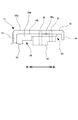
- FIG. 4 is a cross-sectional view showing a structure of a side frame, and is a view showing a cross section AA in FIG.
- FIG. 4 is a cross-sectional view showing the connecting frame attached to the side frame, and is a cross-sectional view taken along the line BB in FIG. 3.
- It is a schematic side view which shows the modification of the vehicle seat which concerns on one Embodiment of this invention. It is a figure which shows the modification about the positional relationship of a side frame, a connection frame, and an actuator.
- FIGS. 2, 4, 5, 6, 7, 8, and 9 the illustration of the actuator and the fixing bolt is omitted for the sake of easy understanding of the structure of the seat frame.
- the height adjusting mechanism 4 and the slide rail mechanism R described later are not shown in FIG.
- the front-rear direction is a direction that matches the traveling direction of the vehicle.
- the width direction is a direction along the lateral width of the vehicle, more specifically, the left-right direction, and corresponds to the width direction of the vehicle seat of the present invention.
- the vertical direction is the vertical direction of the vehicle seat.
- the seat S is substantially the same as a known vehicle seat in terms of the basic structure, and is particularly used in the present embodiment as a front seat disposed in front of the rear seat.
- the present invention is not limited to this, and the present invention is also applicable to a vehicle seat frame that is a rear seat.
- the seat S includes a seat back S1, a seat cushion S2, and a headrest S3 as main components.
- the main frame F forming the skeleton of the main seat S includes a seat back frame F1 provided in the seat back S1 and a seat cushion frame F2 provided in the seat cushion S2, as shown in FIG.
- a guide stay fs that supports the main body of the headrest S3 is fixed to the upper portion of the seat back frame F1 by inserting a pillar S3a extending from the lower portion of the headrest S3.
- the frame F is composed of a metal member, and welding, particularly laser welding is used as a method of joining the structural parts of the frame. As shown in FIG. 2, the seat back frame F1 and the seat cushion frame F2 assembled using this laser welding are constructed so as to form a rectangular frame shape.
- the lower ends of the side frames 11 provided at both ends in the width direction of the seat back frame F1 are assembled to the rear ends of the side frames 1 provided at both ends in the width direction of the seat cushion frame F2.
- the lower end portion of the side frame 11 is assembled to the rear end portion of the side frame 1 via the reclining mechanism 3 illustrated in FIG.
- the reclining mechanism 3 is operated by an occupant operating an operation unit (not shown), and swings the seat back S1 so as to fall forward or backward relative to the seat cushion S2.
- the reclining mechanism 3 is individually provided for each of the side frames 11 provided at both ends in the width direction of the seat back frame F1, and laser welding is performed on the lower part of the outer side surface 12a of each side frame 11. It is attached.
- the reclining mechanism 3 is welded to the rear end portion of the inner wall surface of the side frame 1 on the surface opposite to the side welded to the side frame 11.
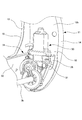
- each reclining mechanism 3 is a known structure, and includes a reclining mechanism main body 3a and a through shaft 3b extending in the width direction while penetrating the reclining mechanism main body 3a.
- the portion of the reclining mechanism main body 3a joined to the side frame 11 is joined to the opposite side, specifically, the side frame 1 of the seat cushion frame F2.
- the side frame 11 to which the reclining mechanism 3 is attached rotates relative to the seat cushion S2 around the through shaft 3b. That is, the seat back S1 swings around the through shaft 3b with respect to the seat cushion S2.
- the penetrating shaft 3b is a rotating shaft that rotates to drive the reclining mechanism 3, and is also a swinging shaft when the seat back S1 swings with respect to the seat cushion S2 by the reclining mechanism 3.
- the through shaft 3 b is a common shaft between the reclining mechanism 3 attached to one side frame 11 and the reclining mechanism 3 attached to the other side frame 11. That is, the penetrating shaft 3 b penetrates the side wall 12 of one side frame 11, goes to the other side frame 11 along the width direction, and further penetrates the side wall 12 of the side frame 11.
- shaft 3b penetrates the corresponding reclining mechanism main body 3a, and also the side frame 1 of the seat cushion frame F2 located beside the reclining mechanism main body 3a. It penetrates to. That is, in the sheet S, the through shaft 3b is rotatably provided in a state of penetrating the side wall 12 and the side frame 1 of the side frame 11 in the width direction. In other words, the reclining mechanism 3 is attached to the side wall 12 in a state where the through shaft 3 b penetrates the side wall 12 of the side frame 11.
- the actuator 50 is connected to the reclining mechanism 3 via the side wall 12 in a state of engaging with a portion of the through shaft 3b that penetrates the side wall 12 of the side frame 11 and is inside the width direction of the side wall 12.
- the actuator 50 is bolted to the side frame 11 in order to restrict the actuator 50 itself from rotating with respect to the side frame 11 when rotating the output shaft.
- a slide rail mechanism R for disposing the seat S so as to be slidable in the front-rear direction with respect to the vehicle body floor is disposed below the seat cushion S2.
- a height adjusting mechanism 4 for adjusting the seat height is provided between the seat cushion S2 and the slide rail mechanism R in the vertical direction. The height adjustment mechanism 4 operates when the occupant operates the operation lever 5 shown in FIG.
- the height adjustment mechanism 4 uses a driving force generated by operating the operation lever 5 to rotate the link that connects the seat cushion frame F2 and the slide rail mechanism R.
- the seat height is adjusted by rotating 6.
- each rotation link 6 is rotatably supported by a support portion Rx provided in the slide rail mechanism R so as to protrude upward on the upper rail Ru. Moreover, the other end part of each rotation link 6 is rotatably attached to the side frame 1 of the seat cushion frame F2.
- a sector gear 7a is formed on the rear rotating link 6 located on one end side in the width direction of the rotating link 6, and a pinion gear 7b is engaged with the sector gear 7a.
- the pinion gear 7b is connected to the operation lever 5 by a connecting shaft (not shown).
- the operation lever 5 is set so as to be positioned on the side of the seat cushion S2, and further, between the side frame 1 of the seat cushion frame F2 and the operation lever 5 is not shown.
- a brake mechanism is provided. The brake mechanism applies a frictional force to the connecting shaft that connects the operation lever 5 and the pinion gear 7b when the height adjusting mechanism 4 is not driven, that is, when the operation lever 5 is not operated.
- the seat height is maintained by restricting unintentional rotation of the shaft.
- the seat back frame F1 in the main frame F includes a side frame 11 disposed at both ends in the width direction, an upper frame 21 that connects the upper ends of the side frames 11, and a lower end of the side frame 11. It has a lower member frame 31 as a communication frame for connecting them together.
- the upper frame 21 is a portion that forms the upper end of the seat back frame F1, as shown in FIGS.
- the upper frame 21 includes a bent portion 22 that is bent downward in a U-shape so that both ends are directed downward, and an upper member frame 23 that is bridged from one end of the bent portion 22 toward the other end. And is composed of.
- the bending portion 22 is formed by bending a metal pipe.
- two portions that are crushed so as to form a plane on the front side are provided in a portion of the bent portion 22 that extends along the width direction.
- This crushing area is provided symmetrically in the bending portion 22, and the above-described guide stay fs is fixed to the plane formed on the front side of each crushing area by laser welding.
- the upper member frame 23 is formed by processing a sheet metal material, and the end of the upper member frame 23 is applied to the end of the bent portion 22 that is bent and extends downward. With laser welding.
- a plurality of rectangular openings 23a are formed at regular intervals in a region located at the center in the extending direction.
- the side frame 11 is a portion that extends in the vertical direction, forming both ends in the width direction of the seat back frame F1.
- each side frame 11 is bent in a substantially arcuate shape so that the upper end portion thereof is located somewhat behind the lower end portion.
- each side frame 11 is shape
- each side frame 11 includes a side wall 12 located on the outer side in the width direction, and a rear wall 13 extending inward in the width direction from the rear end of the side wall 12.
- the side wall 12 extends substantially straight in the vertical direction, and when viewed from the side along the width direction, the side wall 12 has a sharp shape with a narrower width as the upper end portion is directed upward, and the central portion is gently It has a curved shape, and its lower end has a semi-elliptical shape.
- a plurality of holes are formed in the side wall 12, and one of the holes 12 c is formed in the lower end portion of the side wall 12.
- the through-shaft for driving the reclining mechanism 3 described above is formed in the hole. 3b is inserted.
- the other hole is a bolt hole 12d that is positioned above the hole 12c into which the through shaft 3b is inserted, and into which the bolt 51 for preventing rotation of the actuator 50 described above is inserted.
- one of the remaining holes is a hole for fixing the side frame 11 when assembling the seat back frame F1, particularly when welding the members constituting the seat back frame F1, A fixing jig (not shown) is inserted into the hole during welding.
- the reclining mechanism 3 is attached to the outer side surface 12a located on the outer side in the width direction among the side surfaces of the side wall 12. More specifically, in the present sheet S, the reclining mechanism 3 is attached to a portion located slightly above the lower end of the side wall 12 by laser welding.
- the laser is irradiated to the inner side surface 12b located on the back side of the outer side surface 12a in the width direction among the side surfaces of the side wall 12. For this reason, the unevenness
- a portion of the reclining mechanism 3 that is joined to the side wall 12 of the side frame 11, more specifically, a portion of the reclining mechanism main body 3a that faces the side wall 12 is circular. Yes. Therefore, in this seat S, the region where the reclining mechanism 3 is attached to the outer surface 12a on the side wall 12 of each side frame 11 is a circular region M when viewed from the width direction, as shown in FIG. . A hole into which the above-described through shaft 3b is inserted is formed at the center position of the circular region M.
- a side wall flange 14 that is bent inward in the width direction is formed at the front end of the side wall 12.
- the side wall flange 14 corresponds to a side wall bent portion, and is provided from the upper end to the lower end of the side wall 12 in order to reinforce the side wall 12.
- the lower end portion of the side wall 12 has a semi-elliptical shape as described above, and the side wall side flange 14 provided at the lower end portion of the side wall 12 is rearward from the front along the outer edge of the lower end portion of the side wall 12. It is formed in an arc shape so as to go around.
- the rear wall 13 is adjacent to the rear end portion of the side wall 12 in a state of intersecting with the side wall 12, and in this sheet S, the angle between the rear wall 13 and the side wall 12 is about 90 degrees.
- the outer end in the width direction of the rear wall 13 forms a corner of the side frame 11 together with the rear end of the side wall 12.
- the upper end of the rear wall 13 is at a position slightly lower than the upper end of the side wall 12, and the lower end of the rear wall 13 is at a position slightly higher than the lower end of the side wall 12.
- a substantially trapezoidal member frame is attached to the lower end of the rear wall 13 so that the amount of extension to the inner side in the width direction is larger than the portion located above the portion.
- a portion 13a is formed.
- a lower member frame 31, which will be described later, is attached to the member frame attaching portion 13a.
- a slot 16 formed so as to be substantially horizontal across both the side wall 12 and the rear wall 13 is formed in a boundary portion between the side wall 12 and the rear wall 13, that is, in a corner portion of the side frame 11. ing.
- the long holes 16 are formed at the corners of the side frame 11, for example, the side frame 11 tilts backward when a collision load from the rear is applied to the vehicle on which the seat S is mounted. It is easy to deform.
- the long hole 16 corresponds to a fragile portion, and is deformed first in the side frame 11 when a collision load is applied from the rear (strictly, so as to be crushed vertically). It is a starting point when the side frame 11 is deformed.
- a rear wall side flange 15 bent to the front side is formed at the inner end of the rear wall 13 in the width direction.
- the rear wall side flange 15 is formed downward from the upper end of the rear wall 13 in order to reinforce the rear wall 13, and extends over the upper end portion of the member frame mounting portion 13a.
- a rear wall side flange 15 is formed in a region of the rear wall 13 located below the member frame attachment portion 13a.
- the flange 15 is not formed in the outer edge part of the member frame attachment part 13a in the part which exists in the width direction inside, and the part which exists in a lower end side in order to avoid interference with the lower member frame 31.
- the rear wall side flange 15 formed at the lower end portion of the rear wall 13 is a side wall formed so as to wrap around at the lower end portion of the side wall 12 at the outer end portion in the width direction. It is continuous with the side flange 14. Thereby, the rigidity of the entire side frame 11 is further improved.
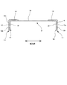
- the lower member frame 31 is a substantially U-shaped member when viewed from above, and is formed by processing a single sheet metal material.
- the lower member frame 31 includes a first extension portion 32 that extends along the width direction, and a second extension portion 33 that extends forward from both ends of the first extension portion 32 in the width direction. ing.
- the first extending portion 32 is a portion that is disposed between the side frames 11 in the width direction and is attached to the rear wall 13 in the side frame 11, particularly the member frame attaching portion 13a described above. More specifically, each end portion in the extending direction of the first extending portion 32 is attached to the member frame attaching portion 13a by laser welding in a state of being in contact with the front surface of the member frame attaching portion 13a. Yes.
- the lower member frame 31 is attached to a part of the side frame 11 located below the part where the long hole 16 is formed. That is, the lower member frame 31 is attached to the side frame 11 at a position avoiding the long hole 16 in the vertical direction. As a result, the effect that the lower member frame 31 is attached and the rigidity is improved does not easily reach around the long hole 16, so that the long hole 16 is easily deformed when a collision load is applied from the rear.
- a through-hole (not shown) formed in the attachment portion 13 a when attached to the member frame attachment portion 13 a is formed at the extending direction end of the first extension portion 32.
- a communicating hole 32b is formed.
- the hole 32b is a hole for fixing the lower member frame 31 when the seat back frame F1 is assembled, particularly when the members constituting the seat back frame F1 are welded.
- a fixing jig (not shown) is inserted during welding.
- the lower end position of the first extending portion 32 is the lower end at the end portion in the extending direction at the center portion in the extending direction. It is located somewhat above the position. That is, in the sheet S, the first extending portion 32 has a shape in which the lower end is somewhat raised at the central portion in the extending direction.
- crew's leg of a rear seat may enter into the space located under the lower member frame 31 in a front seat.
- the first extension part 32 located above the occupant's leg if the lower end of the center part in the extension direction is located above the lower end of the end part in the extension direction, It is possible to suppress the occupant's legs from interfering with the lower member frame 31.
- the end portion in the extending direction of the first extending portion 32 is wider in the vertical direction than the central portion in the extending direction, whereby the rigidity of the lower member frame 31 is ensured.
- a raised portion 32a (in other words, a portion where the rear surface is recessed in an arc shape) is formed in the central portion of the first extension portion 32 in the vertical direction. ing.
- the raised portion 32 a is a so-called reinforcing bead, and is formed slightly longer along the extending direction of the first extending portion 32.
- a first extension part upper flange 34 bent to the front side is formed at the upper end part of the first extension part 32.
- the first extending portion upper flange 34 is formed from one end to the other end of the first extending portion 32 in order to reinforce the first extending portion 32.
- first extending portion lower flange 35 bent forward is formed at the lower end portion of the first extending portion 32 from one end to the other end in the extending direction of the first extending portion 32. Thereby, the rigidity of the lower member frame 31 is further improved.
- the second extending portion 33 is adjacent to both ends in the extending direction of the first extending portion 32 in a state of intersecting with the first extending portion 32.
- the second extending portion 33 and the first extending portion 32 are adjacent to each other.
- the angle between the two extending portions 33 is about 90 degrees.
- the rear end portion of the second extending portion 33 forms a corner portion of the lower member frame 31 together with the extending direction end portion of the first extending portion 32.
- the lower member frame 31 is attached to the above-mentioned member frame attaching part 13a so that the corner
- the second extending portion 33 is positioned on the inner side of the side wall 12 of the side frame 11 in the width direction and overlaps the side wall 12. More specifically, the second extending portion 33 is attached to the side wall 12 by laser welding in a state where the second extending portion 33 is in contact with the inner side surface 12b of the side wall 12.
- the second extending portion 33 of the lower member frame 31 is disposed in contact with the inner side surface 12b of the side wall 12 of the side frame 11, the side of the side wall 12 of the side frame 11 is disposed.
- the rigidity, particularly the rigidity against the load acting in the width direction is improved, and the side frame 11 is prevented from falling down. That is, by arranging the second extending portion 33 so as to overlap the side wall 12 of the side frame 11, the rigidity can be improved to the extent that the side frame 11 is prevented from falling down.
- the second extending portion 33 functions as a mounting bracket for mounting the actuator 50 on the inner side in the width direction of the side wall 12 of the side frame 11 as shown in FIG. That is, in this sheet S, when the actuator 50 is attached to the inner side surface 12b of the side wall 12 of the side frame 11, the mounting bracket is joined to the inner side in the width direction of the side wall 12, and the actuator 50 is fixed to the mounting bracket. Yes. Specifically, a bolt hole 33a is formed in the mounting bracket, and the bolt hole 12a and the bolt hole 12d formed in the side wall 12 of the side frame 11 are in communication with each other. Fifty detent bolts 51 are inserted.
- the 2nd extension part 33 of the lower member frame 31 bears the function as said mounting bracket.
- the mounting brackets are disposed at both ends of the lower member frame 31 and are integrated with the lower member frame 31.
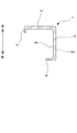
- the second extending portion 33 has a C-shape when viewed from the width direction. That is, in the 2nd extension part 33 with which this sheet
- the lower half region of the front end portion of the second extending portion 33 is cut out in a circular shape so as to be continuous with the punched portion.
- the second extending portion 33 is disposed above the circular punching portion and below the circular punching portion.
- the upper portion 36 and the lower portion 37 are both joined to the side wall 12 by laser welding in a state where they are in contact with the inner side surface 12b of the side wall 12 of the side frame 11.
- the portion of the second extending portion 33 punched out in a circular shape is not naturally joined to the side wall 12 of the side frame 11.
- seat S the reclining mechanism 3 is arrange
- the reclining mechanism 3 is attached to the outer side surface 12a in the region where the upper portion 36 and the lower portion 37 of the second extending portion 33 are in contact with the inner side surface 12b on the side wall 12 of the side frame 11. This means that you are out of the area.
- irregularities as welding marks at the time of laser welding may be formed on the inner side surface 12 b. Since the second extending portion 33 is attached to the inner side surface 12b of the side wall 12 while avoiding the portion where the unevenness is formed, the lower member frame 31 including the second extending portion 33 can be attached favorably.
- this sheet S the region where the reclining mechanism 3 is attached to the outer side surface 12a in the side wall 12 is circular as seen from the width direction as described above.
- the center portion of the second extending portion 33 of the lower member frame 31 is punched into a circular shape so as to match the circular region M.
- the 2nd extension part 33 is joined to the side wall 12 so that the outer edge of the circular area
- the region where the second extending portion 33 is in contact with the inner side surface 12b in the side wall 12 is a C-shape along the outer edge of the circular region M described above when viewed from the width direction. It is an area. More specifically, in the upper portion 36 of the second extending portion 33, as shown in FIGS. 6 and 7, the lower portion of the center portion in the front-rear direction is cut out in a semicircular shape. ing. And the 2nd extension part 33 is attached to the side wall 12 so that the edge of this notch and the upper part of the outer edge of the circular area
- the lower portion 37 of the second extending portion 33 extends in an arc shape toward the front as shown in FIGS. And the 2nd extension part 33 is attached to the side wall 12 so that the said lower part 37 may follow the lower part of the outer edge of the circular area
- the lower portion 37 is a portion of the second extending portion 33 that is disposed below the circular region M described above, and extends in an arc shape along the outer edge of the circular region M. Yes.
- the second extending portion 33 has the outer edge of the circular region M described above (the region where the reclining mechanism 3 is attached to the side wall 12 of the side frame 11) as viewed from the width direction. It is a C-shaped shape along.
- the second extending portion 33 is joined to the side wall 12 so that the circular region M and the circular punched portion of the second extending portion 33 coincide with each other.
- the circular region M described above and the circular punched portion of the second extending portion 33 may be matched.
- the reclining mechanism 3 is first attached to the side wall 12 of the side frame 11 by laser welding, and then the lower member frame 31 is attached to the side frame 11.
- the reclining on the side wall 12 of the side frame 11 is performed. It becomes easier to attach the lower member frame 31 while avoiding the attachment portion of the mechanism 3. That is, when assembling the seat back frame F1 by the above assembling procedure, it is more effective to punch out the central portion of the second extending portion 33 in a circular shape along the outer edge of the circular region M described above. It will be a thing.
- the connecting portion 40 is located behind the region where the reclining mechanism 3 is attached on the side wall 12 and has a shape along the outer edge of the region.
- the front ends of the upper part 36 and the lower part 37 are spaced apart in the vertical direction.
- the shape of the second extending portion 33 that functions as the mounting bracket of the actuator is a shape that avoids the region where the reclining mechanism 3 is attached on the side wall 12 of the side frame 11. Accordingly, the second extending portion 33 can be joined to the inner side surface 12b of the side wall 12 of the side frame 11 while avoiding interference with the rotating shaft for driving the reclining mechanism 3, that is, the through shaft 3b. Furthermore, since the front end portion of the second extension portion 33 is open, it is possible to easily join the second extension portion 33 to the inner side surface 12b of the side wall 12 while avoiding interference with the through shaft 3b. Is possible.
- the second extending portion 33 is C-shaped along the outer edge of the region where the reclining mechanism 3 is attached to the side wall 12 of the side frame 11 when viewed from the width direction. Therefore, the second extending portion 33 can be efficiently joined to the inner side surface 12b of the side wall 12.
- the lower portion 37 of the second extending portion 33 wraps around from the rear of the through shaft 3 b to the front of the through shaft 3 b. It extends in an arc shape.
- the upper portion 36 of the second extending portion 33 extends from the rear of the through shaft 3b to the front of the through shaft 3b.
- the upper portion 36 and the lower portion 37 of the second extending portion 33 are laser-welded to the side wall 12 of the side frame 11, respectively.
- seat S as shown in FIG. 7, the welding area
- the welding region X2 between the lower portion 37 and the side wall 12 extends in an arc shape in the front-rear direction so that a part of the welding region X2 is located behind the through shaft 3b.
- each welding region X1, X2 is a region having a certain length in the front-rear direction, so that each of the upper portion 36 and the lower portion 37 of the second extending portion 33 is provided. Is well fixed to the side wall 12 of the side frame 11. Furthermore, since each welding area
- the welding region X1 between the upper portion 36 and the side wall 12 is an arc-shaped region corresponding to about 3 of the circumference centering on the through shaft 3b, and the lower portion 37 and the side wall 12.
- the welding area X2 is an arc-shaped area corresponding to about 1/6 of the circumference.
- the two welding regions X1, X2 are separated from each other.
- both the welding regions X1 and X2 are less than one circumference around the through shaft 3b and are separated from each other. For this reason, at the time of assembling the seat back frame F1, welding work is performed more easily than in the case where laser welding is performed continuously for one circumference around the through shaft 3b.
- a bolt hole 33a is formed at the front end of the upper portion 36.
- the bolt hole 33a is formed to fix the actuator 50, and is a hole for inserting the bolt 51 for preventing rotation of the actuator 50 as described above.
- seat S as shown in FIG. 7, the site
- the upper portion 36 and the lower portion 37 of the second extending portion 33 are respectively formed with flanges bent inward in the width direction. More specifically, the upper part 36 of the second extension part 33 is formed with a second extension part upper flange 38 whose upper end part is bent inward in the width direction.
- the second extending portion upper flange 38 corresponds to a bent portion, and is formed from the front end to the rear end of the upper portion 36 in order to reinforce the second extending portion 33.
- the rigidity of the lower member frame 31 itself is increased by forming the reinforcing flange 38 at the upper end portion of the upper portion 36 of the second extending portion 33. As a result, the side to which the frame 31 is attached. The rigidity of the frame 11 is also improved.
- the 2nd extension part upper side flange 38 is following the 1st extension part upper side flange 34 formed in the upper end part of the 1st extension part 32 in the rear-end part. Yes. As a result, the rigidity of the entire lower member frame 31 is further improved.
- the front end portion of the second extending portion upper flange 38 is cut away as shown in FIG. More specifically, the portion of the second extending portion upper flange 38 that is adjacent to the formation portion of the bolt hole 33a in the upper portion 36 (hereinafter referred to as the adjacent portion 38a) is not adjacent to the formation portion of the bolt hole 33a.
- the amount of extension inward in the width direction is shorter than that of the portion (hereinafter, non-adjacent portion 38b). Since the adjacent portion 38a faces the periphery of the portion of the actuator 50 where the bolt 51 is attached, the second extending portion upper flange 38 can be formed while suppressing interference with the actuator 50 by the above-described configuration. Become.
- a second extension portion lower flange 39 whose lower end portion is bent inward in the width direction is formed in the lower portion 37 of the second extension portion 33.
- the second extension portion lower flange 39 corresponds to a second extension portion side bent portion, and is formed from the front end to the rear end of the lower portion 37 in order to reinforce the second extension portion 33.
- the second extending portion lower flange 39 also extends in an arc shape. .
- seat S as shown in FIG. 6, in the state which the 2nd extension part 33 was joined to the side wall 12, the front-end part of the 2nd extension part lower side flange 39 is the side wall 12 of the side frame 11 mentioned above.
- the side wall side flange 14 formed on the side wall 12 it overlaps with the rear end portion extending in an arc shape at the lower end position of the side wall 12 in the vertical direction.
- the lower part 37 of the second extension part 33 is such that the second extension part lower flange 39 is along the side wall flange 14 and the front end part of the second extension part lower flange 39 is the side wall.
- the side flange 14 extends so as to overlap the rear end portion. That is, in the seat S, the lower member frame 31 is attached to the side frame 11 as if the second extending portion lower flange 39 and the side wall flange 14 are continuous. Thereby, the integration of the lower member frame 31 and the side frame 11, particularly the lower end portion of the side wall 12, is enhanced, and the rigidity around the portion of the side frame 11 where the lower member frame 31 is attached is further improved.
- the second extension portion lower flange 39 is connected to the first extension portion lower flange 35 formed at the lower end portion of the first extension portion 32 at the rear end portion. Yes. Thereby, the rigidity of the whole lower member frame 31 is further improved.
- the configuration example of the seat frame of the vehicle seat according to the present invention has been described.
- the above-described embodiment is merely an example for facilitating the understanding of the present invention, and the present invention is limited. Not what you want. That is, the shape, dimensions, arrangement, and the like of the members described above can be changed and improved without departing from the spirit of the present invention, and the present invention includes its equivalents. is there.
- the vehicle seat according to the modified example (hereinafter referred to as the seat HS according to the modified example) has one configuration in the width direction of the seat back S1 as shown in FIG. 13 in addition to the same configuration as the vehicle seat according to the above-described embodiment.
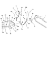
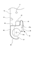
- the armrest S4 is pivotable in the vertical direction and the front-rear direction with respect to the seat back S1, and the armrest pivot shaft 9 as the pivot shaft is supported on the side wall 12 of the side frame 11 as shown in FIG. Has been. More specifically, the armrest rotating shaft 9 is supported by a portion of the side wall 12 that is positioned above a portion to which the reclining mechanism 3 and the lower member frame 31 are attached.
- the additional extending portion 41 corresponds to the extending portion, is provided at a position ahead of the armrest rotating shaft 9, and is joined to the inner side surface 12b of the side wall 12 of the side frame 11 by welding. Thereby, the rigidity of the part located ahead of the side frame 11, especially the armrest rotating shaft 9 with respect to the load generated when the armrest S4 rotates is improved.
- an additional extending portion 41 is provided in the upper portion 36 just above the formation site of the bolt hole 33a.
- the actuator 50 regarding the 2nd extension part 33 of the lower member frame 31.
- the upper end of the additional extending portion 41 does not reach the support position of the armrest rotating shaft 9 and is somewhat below the support position.
- a plurality of holes are formed in the side wall 12 of the side frame 11, but the additional extension portion 41 avoids the holes so as not to block these holes. Be joined.
- a long hole 16 is formed in the rear end portion of the side wall 12 of the side frame 11 as a fragile portion that is deformed to tilt the side frame 11 backward when a collision load is applied from the rear.
- the additional extension part 41 is provided in the front position rather than said long hole 16, as shown in FIG. In such a positional relationship, even if the additional extending portion 41 is provided, the influence does not reach the long hole 16 and the long hole 16 is well deformed when a collision load is applied from the rear. To come.
- the present invention is also applicable to cases other than the embodiments described above.
- the second extending portion 33 of the lower member frame 31 is in contact with the inner side surface 12 b on the side wall 12 of the side frame 11.
- the region where the reclining mechanism 3 is attached to the outer surface 12a in the side wall 12 is a circular region M when viewed from the width direction.
- abutting to the inner surface 12b in the side wall 12 becomes a C-shaped area
- the second extending portion 33 has the upper portion 36 disposed above the circular region M and the lower portion 37 disposed below the circular region M.
- the 2nd extension part 33 may be the structure which has only the part corresponded to either one among said upper part 36 and lower part 37. .
- the reinforcing flanges (the second extending portion upper flange 38 and the second extending portion lower flange 39) are formed in each of the upper portion 36 and the lower portion 37.
- the structure in which the flange for reinforcement is not formed may be sufficient.
- the front end portions of the upper portion 36 and the lower portion 37 are separated from each other and the rear end portions are connected to each other.
- the present invention is not limited to this.
- the rear end portions of the lower portion 37 may be separated from each other and the front end portions may be connected to each other.
Landscapes
- Engineering & Computer Science (AREA)
- Aviation & Aerospace Engineering (AREA)
- Transportation (AREA)
- Mechanical Engineering (AREA)
- Seats For Vehicles (AREA)
Description
また、補強ブラケットを溶接にてサイドフレームに接合する際には、アクチュエータ固定用のボルトと上述のシャフトとの位置関係が変動せずに安定するように溶接領域を設定する必要がある。その一方で、溶接作業が容易に行われるように補強ブラケットとサイドフレームとの溶接領域を設定することが望まれる。
また、補強ブラケットとサイドフレームとの接合状態を安定させるためには、補強ブラケット自体の剛性を確保する必要がある。そのため、アクチュエータの取り付け時に補強ブラケットがアクチュエータと干渉しないように配慮しつつ、補強ブラケットの剛性を向上させることが求められる。
さらに、アームレストを備える車両用シートにおいてサイドフレームに当該アームレストの回動軸が支持されているときには、アームレストの回動によってサイドフレームに生じる荷重を考慮して補強ブラケットを設ける必要がある。
また、本発明の他の目的は、アクチュエータ取り付け用のブラケットを設けつつも部品点数の削減を実現することが可能な車両用シートのシートフレームを提供することである。
また、本発明の他の目的は、アクチュエータ取り付け用のブラケットを溶接にてサイドフレームに接合する際に、アクチュエータ固定用のボルトとリクライニング機構駆動用のシャフトとの位置関係が安定するように溶接領域が設定された車両用シートのシートフレームを提供することである。特に、溶接作業が容易に行われるように溶接領域が適切に設定された車両用シートのシートフレームを提供することである。
また、本発明の他の目的は、アクチュエータ取り付け用のブラケットがアクチュエータと干渉しないように配慮しながら当該ブラケットの剛性を向上させることが可能な車両用シートのシートフレームを提供することである。
さらに、本発明の他の目的は、アームレストを備える車両用シートにおいてアームレストの回動によってサイドフレームに生じる荷重を考慮した形状をなすアクチュエータ取り付け用のブラケットを備えた車両用シートのシートフレームを提供することである。
上記の構成であれば、連結フレームの端部が取り付けブラケットとして機能する。つまり、取り付けブラケットを別部材で設ける構成と比較して、部品点数をより少なくすることが可能となる。
上記の構成であれば、ボルト穴とリクライニング機構の取り付け領域との間で取り付けブラケットをサイドフレームに溶接するのでボルト穴とリクライニング機構駆動用の回転軸との間に溶接領域が存在することになる。これにより、ボルト穴及び回転軸の各々の位置が変化し難くなるため、アクチュエータ固定用のボルトと上記回転軸との位置関係が安定するようになる。
上記の構成であれば、サイドフレームの側壁のうちのリクライニング機構が取り付けられた部分の外縁に応じて、取り付けブラケットを効率的にサイドフレームに接合させることが可能となる。
上記の構成であれば、取り付けブラケットの上方部及び下方部の各々をサイドフレームの側壁に対して良好に接合することができる。さらに、各溶接領域が車両用シートの前後方向に延びているので、前後方向に作用する荷重に対する強度を確保することが可能となり、取り付けブラケットの上方部及び下方部の各々がサイドフレームの側壁に接合された状態を安定的に保持することが可能となる。
上記の構成であれば、取り付けブラケットに折れ曲がり部が形成されていることにより、取り付けブラケットの剛性が向上する。
折れ曲がり部のうち、ボルト穴の形成部位と隣接する部分は、アクチュエータの一部、具体的には、固定用のボルトが取り付けられる部分周辺と対向する。したがって、上記の構成のように、折れ曲がり部のうち、ボルト穴の形成部位と隣接する部分の延出量がより短くなっていれば、アクチュエータとの干渉を抑えながら折れ曲がり部を形成することが可能となる。
アームレストの回動軸がサイドフレームの側壁に支持されている場合、アームレストが回動すると、サイドフレームのうち、回動軸よりも前方に位置する部分に荷重が掛かる。これに対して、上記の構成では、取り付けブラケットの上方部が、上記の回動軸に向かって上側に延出する延出部が回動軸よりも前方位置に設けられている。これにより、アームレストの回動時に発生する上記の荷重に対するサイドフレームの剛性を向上させることが可能となる。
上記の構成であれば、上記の延出部が脆弱部を避けるために脆弱部よりも前側位置にあるので、車両用シートに後方からの衝突荷重が掛かった際には、脆弱部が良好に変形するようになる。
本発明の請求項2に記載の車両用シートのシートフレームによれば、取り付けブラケットを別部材で設ける構成と比較して、部品点数がより少なくなる。
本発明の請求項3に記載の車両用シートのシートフレームによれば、ボルト穴及び回転軸の各々の位置が変化し難くなるため、アクチュエータ固定用のボルトと上記回転軸との位置関係が安定するようになる。
本発明の請求項4に記載の車両用シートのシートフレームによれば、サイドフレームの側壁においてリクライニング機構が取り付けられている領域の外縁に応じて、取り付けブラケットが効率的にサイドフレームに接合される。
本発明の請求項5に記載の車両用シートのシートフレームによれば、取り付けブラケットの上方部及び下方部の各々がサイドフレームの側壁に対して良好に接合される。また、取り付けブラケットの上方部及び下方部の各々がサイドフレームの側壁に接合された状態が安定的に保持される。
本発明の請求項6に記載の車両用シートのシートフレームによれば、取り付けブラケットの剛性が向上する。
本発明の請求項7に記載の車両用シートのシートフレームによれば、アクチュエータとの干渉を抑えつつ、折れ曲がり部を形成することが可能となる。
本発明の請求項8に記載の車両用シートのシートフレームによれば、アームレストの回動時にサイドフレームに発生する荷重に対して、サイドフレームの剛性が向上する。
本発明の請求項9に記載の車両用シートのシートフレームによれば、車両用シートに後方からの衝突荷重が掛かった際に脆弱部が良好に変形するようになる。
本シートSは、基本構造の面では、公知の車両用シートと略同様であり、本実施形態では特に、後部座席の前に配置された前部座席として利用されるものである。但し、これに限定されるものではなく、本発明は、後部座席である車両用シートのシートフレームにも適用可能である。
なお、アクチュエータ50は、出力軸を回転させる際にアクチュエータ50自体がサイドフレーム11に対して回転するのを規制するために、サイドフレーム11にボルト止めされている。
シートバックフレームF1は、図2及び3に示すように、幅方向の両端部に配置されたサイドフレーム11と、サイドフレーム11の上端部同士を連結する上部フレーム21と、サイドフレーム11の下端部同士を連結する連絡フレームとしての下部メンバフレーム31とを有する。
各サイドフレーム11は、図8に示すように、幅方向外側に位置する側壁12と、側壁12の後端から幅方向内側に延出した後壁13とを有する。側壁12は、上下方向に略真っ直ぐに延出しており、側方から幅方向に沿って見ると、上端部が上方に向かうほど幅狭となるように尖った形状をなし、中央部が緩やかにカーブした形状をなし、下端部が半楕円状の形状をなしている。
その一方で、第1延出部32の延出方向端部では、延出方向中央部に比して、上下に幅広となっており、これにより下部メンバフレーム31の剛性が確保されている。
なお、図4に示すように、第2延出部上側フランジ38は、その後端部にて、第1延出部32の上端部に形成された第1延出部上側フランジ34と連続している。これにより、下部メンバフレーム31全体の剛性がより向上している。
S1 シートバック、S2 シートクッション、S3 ヘッドレスト
S3a ピラー
S4 アームレスト
F 本フレーム
F1 シートバックフレーム、F2 シートクッションフレーム
fs ガイドステー
R スライドレール機構、Ru アッパレール、Rx 支持部
M 円形の領域
X1,X2 溶接領域
HS 変形例に係るシート
1 側部フレーム
3 リクライニング機構
3a リクライニング機構本体、3b 貫通軸
4 ハイト調整機構、5 操作レバー、6 回動リンク
7a セクターギア、7b ピニオンギア
9 アームレスト回動軸
11 サイドフレーム
12 側壁
12a 外側面、12b 内側面、12c 穴、12d ボルト穴
13 後壁、13a メンバフレーム取り付け部
14 側壁側フランジ、15 後壁側フランジ
16 長穴
21 上部フレーム、22 折り曲げ加工部
23 上部メンバフレーム、23a 開口
31 下部メンバフレーム
32 第1延出部、32a 隆起部、32b 穴
33 第2延出部、33a ボルト穴
34 第1延出部上側フランジ、35 第1延出部下側フランジ
36 上方部、37 下方部
38 第2延出部上側フランジ
38a 隣接部分、38b 非隣接部分
39 第2延出部下側フランジ、40 連結部
41 追加延出部
50 アクチュエータ、51 ボルト
Claims (9)
- 車両用シートのシートバックが備えるシートバックフレームにおいて前記車両用シートの幅方向の両端部に配置されたサイドフレームと、
前記幅方向に延びた回転軸を備え、該回転軸が回転することにより前記車両用シートのシートクッションに対して前記シートバックを揺動させるリクライニング機構と、
前記回転軸を回転させるために駆動するアクチュエータと、を備え、
前記リクライニング機構は、前記回転軸が前記サイドフレームの側壁を貫通した状態で該側壁に取り付けられ、
前記アクチュエータは、前記回転軸のうちの前記側壁を貫通した部分と係合した状態で、前記側壁の前記幅方向内側の面に接合された取り付けブラケットに固定されており、
前記取り付けブラケットは、前記側壁において前記リクライニング機構が取り付けられている領域より上方に配置された上方部と、前記側壁において前記リクライニング機構が取り付けられている領域より下方に配置された下方部と、を有し、
前記車両用シートの前後方向における前記上方部及び前記下方部の各々の一端部同士が連結し、前記前後方向における前記上方部及び前記下方部の各々の他端部同士が離間していることを特徴とする車両用シートのシートフレーム。 - 前記サイドフレームの下端部同士を連結する連結フレームが備えられ、
前記取り付けブラケットは、前記連結フレームの両端部に配置され、前記連結フレームと一体化していることを特徴とする請求項1に記載の車両シートのシートフレーム。 - 前記上方部には前記アクチュエータを固定するためのボルト穴が形成されており、
前記上方部のうち、前記側壁において前記リクライニング機構が取り付けられている領域と前記ボルト穴との間に位置する部位が前記側壁に溶接されていることを特徴とする請求項1または2に記載の車両用シートのシートフレーム。 - 前記側壁のうちの前記リクライニング機構が取り付けられた部分は、前記幅方向から見て円形の領域となっており、
前記取り付けブラケットは、前記幅方向から見て、前記側壁において前記リクライニング機構が取り付けられている領域の外縁に沿ったC字状の形状となっていることを特徴とする請求項1乃至3のいずれか一項に記載の車両用シートのシートフレーム。 - 前記上方部及び前記下方部は、それぞれ、前記側壁に溶接されており、
前記上方部と前記側壁との溶接領域のうち、少なくとも一部が前記回転軸よりも前方に位置しており、
前記下方部と前記側壁との溶接領域のうち、少なくとも一部が前記回転軸よりも後方に位置していることを特徴とする請求項4に記載の車両用シートのシートフレーム。 - 前記取り付けブラケットの上端部には、前記幅方向の内側に折れ曲がった折れ曲がり部が形成されていることを特徴とする請求項1乃至5のいずれか一項に記載の車両用シートのシートフレーム。
- 前記上方部には前記アクチュエータを固定するためのボルト穴が形成されており、
前記折れ曲がり部のうち、前記取り付けブラケットにおける前記ボルト穴の形成部位と隣接する部分では、前記ボルト穴の形成部位と隣接しない部分に比して、前記幅方向の内側への延出量がより短くなっていることを特徴とする請求項6に記載の車両用シートのシートフレーム。 - 前記側壁のうち、前記取り付けブラケットよりも上方に位置する部分には、前記車両用シートのアームレストが前記シートバックに対して回動する際の回動軸が支持されており、
前記上方部は、前記回動軸に向かって上方に延出した延出部を有し、
該延出部は、前記回動軸よりも前方位置に設けられていることを特徴とする請求項1乃至7のいずれか一項に記載の車両用シートのシートフレーム。 - 前記側壁の後端部には、後方からの衝突荷重が掛かった際に前記サイドフレームを後傾させるために変形する脆弱部が形成されており、
前記延出部は、前記脆弱部よりも前方位置に設けられていることを特徴とする請求項8に記載の車両用シートのシートフレーム。
Priority Applications (16)
| Application Number | Priority Date | Filing Date | Title |
|---|---|---|---|
| CN201280075441.7A CN104583007B (zh) | 2012-09-03 | 2012-09-03 | 车用座椅的座椅框架 |
| EP12883445.4A EP2894061B1 (en) | 2012-09-03 | 2012-09-03 | Seat frame for vehicle seat |
| JP2014532722A JP6005163B2 (ja) | 2012-09-03 | 2012-09-03 | 車両用シートのシートフレーム |
| MX2015002727A MX354225B (es) | 2012-09-03 | 2012-09-03 | Armazón de asiento para asiento de vehículo. |
| US14/424,312 US9428084B2 (en) | 2012-09-03 | 2012-09-03 | Seat frame for vehicle seat |
| PCT/JP2012/072387 WO2014033962A1 (ja) | 2012-09-03 | 2012-09-03 | 車両用シートのシートフレーム |
| BR112015004391A BR112015004391B8 (pt) | 2012-09-03 | 2012-09-03 | armação de assento para um assento de veículo. |
| US15/249,960 US9815397B2 (en) | 2012-09-03 | 2016-08-29 | Seat frame for vehicle seat |
| US15/810,970 US10266087B2 (en) | 2012-09-03 | 2017-11-13 | Seat frame for vehicle seat |
| US16/389,387 US10604044B2 (en) | 2012-09-03 | 2019-04-19 | Seat frame for vehicle seat |
| US16/834,056 US10967770B2 (en) | 2012-09-03 | 2020-03-30 | Seat frame for vehicle seat |
| US17/222,103 US20210221268A1 (en) | 2012-09-03 | 2021-04-05 | Seat frame for vehicle seat |
| US17/571,581 US11628754B2 (en) | 2012-09-03 | 2022-01-10 | Seat frame for vehicle seat |
| US18/300,442 US11938851B2 (en) | 2012-09-03 | 2023-04-14 | Seat frame for vehicle seat |
| US18/581,458 US12257936B2 (en) | 2012-09-03 | 2024-02-20 | Seat frame for vehicle seat |
| US18/950,332 US20250074280A1 (en) | 2012-09-03 | 2024-11-18 | Seat frame for vehicle seat |
Applications Claiming Priority (1)
| Application Number | Priority Date | Filing Date | Title |
|---|---|---|---|
| PCT/JP2012/072387 WO2014033962A1 (ja) | 2012-09-03 | 2012-09-03 | 車両用シートのシートフレーム |
Related Child Applications (2)
| Application Number | Title | Priority Date | Filing Date |
|---|---|---|---|
| US14/424,312 A-371-Of-International US9428084B2 (en) | 2012-09-03 | 2012-09-03 | Seat frame for vehicle seat |
| US15/249,960 Division US9815397B2 (en) | 2012-09-03 | 2016-08-29 | Seat frame for vehicle seat |
Publications (1)
| Publication Number | Publication Date |
|---|---|
| WO2014033962A1 true WO2014033962A1 (ja) | 2014-03-06 |
Family
ID=50182806
Family Applications (1)
| Application Number | Title | Priority Date | Filing Date |
|---|---|---|---|
| PCT/JP2012/072387 Ceased WO2014033962A1 (ja) | 2012-09-03 | 2012-09-03 | 車両用シートのシートフレーム |
Country Status (7)
| Country | Link |
|---|---|
| US (10) | US9428084B2 (ja) |
| EP (1) | EP2894061B1 (ja) |
| JP (1) | JP6005163B2 (ja) |
| CN (1) | CN104583007B (ja) |
| BR (1) | BR112015004391B8 (ja) |
| MX (1) | MX354225B (ja) |
| WO (1) | WO2014033962A1 (ja) |
Cited By (2)
| Publication number | Priority date | Publication date | Assignee | Title |
|---|---|---|---|---|
| JP2019026052A (ja) * | 2017-07-28 | 2019-02-21 | 株式会社タチエス | 車両用シート |
| US20240123876A1 (en) * | 2021-01-14 | 2024-04-18 | Ts Tech Co., Ltd. | Conveyance seat |
Families Citing this family (17)
| Publication number | Priority date | Publication date | Assignee | Title |
|---|---|---|---|---|
| DE102010043012B4 (de) * | 2010-10-27 | 2022-01-27 | Adient Luxembourg Holding S.À R.L. | Sitzuntergestell für Kraftfahrzeugsitze |
| JP6004863B2 (ja) * | 2012-09-24 | 2016-10-12 | テイ・エス テック株式会社 | シートのフレーム |
| CN104797456B (zh) * | 2012-11-16 | 2016-10-05 | 提爱思科技股份有限公司 | 交通工具座椅 |
| DE102013213995B4 (de) * | 2013-07-17 | 2015-03-26 | Johnson Controls Components Gmbh & Co. Kg | Rückenlehne für einen Fahrzeugsitz und Fahrzeugsitz |
| JP2017065484A (ja) * | 2015-09-30 | 2017-04-06 | アイシン精機株式会社 | 車両用シートリフター装置 |
| JP6651981B2 (ja) * | 2016-05-19 | 2020-02-19 | トヨタ紡織株式会社 | シートバックフレーム |
| CN108284775B (zh) * | 2018-01-30 | 2023-08-29 | 重庆博奥镁铝金属制造有限公司 | 一种汽车座椅靠背骨架结构 |
| JP6604491B2 (ja) * | 2018-03-28 | 2019-11-13 | マツダ株式会社 | 車両用シート構造 |
| JP7200701B2 (ja) * | 2019-01-30 | 2023-01-10 | トヨタ紡織株式会社 | シート |
| CN110435506B (zh) * | 2019-08-23 | 2021-05-07 | 延锋汽车饰件系统有限公司 | 零重力座椅及包含其的汽车 |
| CN110435501B (zh) | 2019-08-23 | 2021-08-27 | 延锋汽车饰件系统有限公司 | 汽车座椅及包含其的汽车 |
| CN119550891A (zh) | 2019-08-28 | 2025-03-04 | 提爱思科技股份有限公司 | 车辆座椅 |
| FR3102418B1 (fr) | 2019-10-25 | 2026-04-10 | Renault Sas | Armature de siège d’un véhicule automobile et siège de véhicule associé |
| JP7374830B2 (ja) | 2020-03-24 | 2023-11-07 | トヨタ紡織株式会社 | 乗物用シートのワイヤハーネス取付構造 |
| US11639125B2 (en) * | 2021-07-19 | 2023-05-02 | Lear Corporation | Vehicle seat assembly and method of assembling |
| FR3138367B1 (fr) * | 2022-07-26 | 2025-11-21 | Faurecia Sieges Dautomobile | Armature de banquette avec une armature de dossier pivotable à liaison pivot et dispositif de rétention intégrés |
| WO2024158850A1 (en) * | 2023-01-24 | 2024-08-02 | Yanfeng International Automotive Technology Co., Ltd. | Seat system for vehicle |
Citations (4)
| Publication number | Priority date | Publication date | Assignee | Title |
|---|---|---|---|---|
| JPS5968449U (ja) * | 1982-10-28 | 1984-05-09 | 本田技研工業株式会社 | 車両用シ−ト装置 |
| JPH04124525U (ja) * | 1991-04-30 | 1992-11-13 | 株式会社タチエス | パワーシートのモータ取付構造 |
| JP2006306188A (ja) | 2005-04-27 | 2006-11-09 | Fuji Kiko Co Ltd | 車両用電動シートリクライニング装置 |
| JP2012131464A (ja) * | 2010-12-24 | 2012-07-12 | Honda Motor Co Ltd | 車両用シート |
Family Cites Families (32)
| Publication number | Priority date | Publication date | Assignee | Title |
|---|---|---|---|---|
| US3544164A (en) * | 1967-07-24 | 1970-12-01 | Toyota Motor Co Ltd | Seat frame construction |
| JPH0613267B2 (ja) * | 1985-09-18 | 1994-02-23 | 日産自動車株式会社 | 乗物用座席 |
| US5769499A (en) * | 1996-06-07 | 1998-06-23 | Lear Corporation | Motor vehicle seat |
| JPH10278644A (ja) | 1997-03-31 | 1998-10-20 | Tachi S Co Ltd | 車両用衝撃吸収シートの衝撃吸収方法および車両用衝撃吸収シート |
| JP2002034712A (ja) | 2000-07-31 | 2002-02-05 | Tachi S Co Ltd | シート・バック・フレーム |
| JP2002187465A (ja) | 2000-12-21 | 2002-07-02 | Fuji Kiko Co Ltd | 車両用シートのクッションフレーム取付構造 |
| US6857698B2 (en) * | 2003-02-21 | 2005-02-22 | Lear Corporation | Seat side impact resistance mechanism |
| JP4210990B2 (ja) | 2003-03-31 | 2009-01-21 | テイ・エス テック株式会社 | 超高張力鋼板製の自動車用シートバックフレーム |
| JP4210989B2 (ja) | 2003-03-31 | 2009-01-21 | テイ・エス テック株式会社 | 超高張力鋼板製の自動車用シートバックフレーム |
| US7066552B2 (en) * | 2003-03-31 | 2006-06-27 | Ts Tech Co., Ltd. | Seat back frame for vehicle seat |
| JP2005119468A (ja) | 2003-10-16 | 2005-05-12 | T S Tec Kk | シートフレーム |
| JP4860932B2 (ja) * | 2005-02-04 | 2012-01-25 | テイ・エス テック株式会社 | 衝撃吸収可能な自動車用シート |
| EP1894769B1 (en) * | 2005-03-31 | 2012-08-29 | TS Tech Co., Ltd. | Seat height adjustment device for automobile |
| US7284800B2 (en) * | 2005-12-30 | 2007-10-23 | Tachi-S Co., Ltd. | Seat back frame for automotive seat |
| JP4922627B2 (ja) * | 2006-02-28 | 2012-04-25 | 富士機工株式会社 | 車両用シートリクライニング装置 |
| US8033602B2 (en) * | 2007-07-20 | 2011-10-11 | Honda Motor Co., Ltd. | Vehicle seat |
| KR101047563B1 (ko) * | 2007-12-14 | 2011-07-07 | 기아자동차주식회사 | 차량용 시트백프레임 어셈블리 |
| JP5470740B2 (ja) * | 2008-05-08 | 2014-04-16 | アイシン精機株式会社 | 車両用シートリクライニング装置 |
| US7976103B2 (en) * | 2008-09-23 | 2011-07-12 | Lear Corporation | Seat assembly having a switch and method of operation |
| US8632126B2 (en) * | 2009-01-21 | 2014-01-21 | Ts Tech Co., Ltd. | Vehicle seat |
| US8434823B2 (en) * | 2009-07-17 | 2013-05-07 | Ford Global Technologies | Reclining seat assembly |
| EP2536588B8 (en) * | 2010-02-19 | 2018-05-02 | Adient Luxembourg Holding S.à r.l. | One-piece seat back structure and method of manufacturing |
| JP5599625B2 (ja) * | 2010-02-26 | 2014-10-01 | テイ・エス テック株式会社 | 車両用シート |
| JP5508064B2 (ja) | 2010-03-03 | 2014-05-28 | テイ・エス テック株式会社 | シートバックフレーム |
| JP5513212B2 (ja) * | 2010-03-30 | 2014-06-04 | 日本発條株式会社 | 車両用シートバック及びこれを備えた車両用シート |
| JP5521729B2 (ja) | 2010-04-20 | 2014-06-18 | トヨタ紡織株式会社 | 乗物用シート |
| JP5666279B2 (ja) | 2010-12-15 | 2015-02-12 | 株式会社タチエス | 車両用シートのシートバックフレーム構造 |
| JP5580727B2 (ja) * | 2010-12-24 | 2014-08-27 | テイ・エス テック株式会社 | 乗物用シート |
| EP2657070B1 (en) | 2010-12-24 | 2018-07-11 | TS Tech Co., Ltd. | Vehicle seat |
| US9511698B2 (en) * | 2011-06-03 | 2016-12-06 | Ford Global Technologist, LLC | Vehicle seat back having support members with integrated recliner heart |
| US9499080B2 (en) * | 2011-06-03 | 2016-11-22 | Ford Global Technologies, Llc | Vehicle seat back member |
| DE102012019810A1 (de) * | 2012-10-10 | 2014-04-10 | Daimler Ag | Sitzanlage, insbesondere Fahrzeugsitz, für einen Kraftwagen |
-
2012
- 2012-09-03 EP EP12883445.4A patent/EP2894061B1/en active Active
- 2012-09-03 WO PCT/JP2012/072387 patent/WO2014033962A1/ja not_active Ceased
- 2012-09-03 CN CN201280075441.7A patent/CN104583007B/zh active Active
- 2012-09-03 JP JP2014532722A patent/JP6005163B2/ja active Active
- 2012-09-03 US US14/424,312 patent/US9428084B2/en active Active
- 2012-09-03 MX MX2015002727A patent/MX354225B/es active IP Right Grant
- 2012-09-03 BR BR112015004391A patent/BR112015004391B8/pt active IP Right Grant
-
2016
- 2016-08-29 US US15/249,960 patent/US9815397B2/en active Active
-
2017
- 2017-11-13 US US15/810,970 patent/US10266087B2/en active Active
-
2019
- 2019-04-19 US US16/389,387 patent/US10604044B2/en active Active
-
2020
- 2020-03-30 US US16/834,056 patent/US10967770B2/en active Active
-
2021
- 2021-04-05 US US17/222,103 patent/US20210221268A1/en not_active Abandoned
-
2022
- 2022-01-10 US US17/571,581 patent/US11628754B2/en active Active
-
2023
- 2023-04-14 US US18/300,442 patent/US11938851B2/en active Active
-
2024
- 2024-02-20 US US18/581,458 patent/US12257936B2/en active Active
- 2024-11-18 US US18/950,332 patent/US20250074280A1/en active Pending
Patent Citations (4)
| Publication number | Priority date | Publication date | Assignee | Title |
|---|---|---|---|---|
| JPS5968449U (ja) * | 1982-10-28 | 1984-05-09 | 本田技研工業株式会社 | 車両用シ−ト装置 |
| JPH04124525U (ja) * | 1991-04-30 | 1992-11-13 | 株式会社タチエス | パワーシートのモータ取付構造 |
| JP2006306188A (ja) | 2005-04-27 | 2006-11-09 | Fuji Kiko Co Ltd | 車両用電動シートリクライニング装置 |
| JP2012131464A (ja) * | 2010-12-24 | 2012-07-12 | Honda Motor Co Ltd | 車両用シート |
Non-Patent Citations (1)
| Title |
|---|
| See also references of EP2894061A4 |
Cited By (2)
| Publication number | Priority date | Publication date | Assignee | Title |
|---|---|---|---|---|
| JP2019026052A (ja) * | 2017-07-28 | 2019-02-21 | 株式会社タチエス | 車両用シート |
| US20240123876A1 (en) * | 2021-01-14 | 2024-04-18 | Ts Tech Co., Ltd. | Conveyance seat |
Also Published As
| Publication number | Publication date |
|---|---|
| US20180065530A1 (en) | 2018-03-08 |
| US10967770B2 (en) | 2021-04-06 |
| US20250074280A1 (en) | 2025-03-06 |
| US12257936B2 (en) | 2025-03-25 |
| US20160368399A1 (en) | 2016-12-22 |
| BR112015004391A2 (pt) | 2017-07-04 |
| US11938851B2 (en) | 2024-03-26 |
| US9815397B2 (en) | 2017-11-14 |
| JP6005163B2 (ja) | 2016-10-12 |
| BR112015004391B1 (pt) | 2020-06-23 |
| MX2015002727A (es) | 2015-05-15 |
| US9428084B2 (en) | 2016-08-30 |
| US20150239369A1 (en) | 2015-08-27 |
| US20230249595A1 (en) | 2023-08-10 |
| EP2894061A4 (en) | 2015-10-28 |
| US20210221268A1 (en) | 2021-07-22 |
| US10266087B2 (en) | 2019-04-23 |
| CN104583007A (zh) | 2015-04-29 |
| MX354225B (es) | 2018-02-19 |
| BR112015004391B8 (pt) | 2020-07-14 |
| US11628754B2 (en) | 2023-04-18 |
| US20200223337A1 (en) | 2020-07-16 |
| EP2894061A1 (en) | 2015-07-15 |
| JPWO2014033962A1 (ja) | 2016-08-08 |
| US20220134923A1 (en) | 2022-05-05 |
| US20190241105A1 (en) | 2019-08-08 |
| US10604044B2 (en) | 2020-03-31 |
| US20240190315A1 (en) | 2024-06-13 |
| EP2894061B1 (en) | 2019-11-06 |
| CN104583007B (zh) | 2016-09-21 |
Similar Documents
| Publication | Publication Date | Title |
|---|---|---|
| JP6005163B2 (ja) | 車両用シートのシートフレーム | |
| JP6005162B2 (ja) | 車両用シートのシートフレーム | |
| US9744884B2 (en) | Vehicle seat having an elevation mechanism and a cushion frame with rigid portions | |
| JP6483773B2 (ja) | 車両用シートのシートフレーム | |
| JP6212173B2 (ja) | 車両用シートのシートフレーム | |
| JP6764119B2 (ja) | 車両用シート | |
| JP2023038344A (ja) | 車両用シートのシートフレーム及び車両用シート |
Legal Events
| Date | Code | Title | Description |
|---|---|---|---|
| 121 | Ep: the epo has been informed by wipo that ep was designated in this application |
Ref document number: 12883445 Country of ref document: EP Kind code of ref document: A1 |
|
| WWE | Wipo information: entry into national phase |
Ref document number: 14424312 Country of ref document: US |
|
| ENP | Entry into the national phase |
Ref document number: 2014532722 Country of ref document: JP Kind code of ref document: A |
|
| WWE | Wipo information: entry into national phase |
Ref document number: MX/A/2015/002727 Country of ref document: MX |
|
| NENP | Non-entry into the national phase |
Ref country code: DE |
|
| WWE | Wipo information: entry into national phase |
Ref document number: 2012883445 Country of ref document: EP |
|
| REG | Reference to national code |
Ref country code: BR Ref legal event code: B01A Ref document number: 112015004391 Country of ref document: BR |
|
| ENP | Entry into the national phase |
Ref document number: 112015004391 Country of ref document: BR Kind code of ref document: A2 Effective date: 20150227 |