WO2014034510A1 - アクチュエータ - Google Patents
アクチュエータ Download PDFInfo
- Publication number
- WO2014034510A1 WO2014034510A1 PCT/JP2013/072361 JP2013072361W WO2014034510A1 WO 2014034510 A1 WO2014034510 A1 WO 2014034510A1 JP 2013072361 W JP2013072361 W JP 2013072361W WO 2014034510 A1 WO2014034510 A1 WO 2014034510A1
- Authority
- WO
- WIPO (PCT)
- Prior art keywords
- side chamber
- piston
- actuator
- pressure
- passage
- Prior art date
- Legal status (The legal status is an assumption and is not a legal conclusion. Google has not performed a legal analysis and makes no representation as to the accuracy of the status listed.)
- Ceased
Links
Images


Classifications
-
- F—MECHANICAL ENGINEERING; LIGHTING; HEATING; WEAPONS; BLASTING
- F15—FLUID-PRESSURE ACTUATORS; HYDRAULICS OR PNEUMATICS IN GENERAL
- F15B—SYSTEMS ACTING BY MEANS OF FLUIDS IN GENERAL; FLUID-PRESSURE ACTUATORS, e.g. SERVOMOTORS; DETAILS OF FLUID-PRESSURE SYSTEMS, NOT OTHERWISE PROVIDED FOR
- F15B15/00—Fluid-actuated devices for displacing a member from one position to another; Gearing associated therewith
- F15B15/18—Combined units comprising both motor and pump
-
- F—MECHANICAL ENGINEERING; LIGHTING; HEATING; WEAPONS; BLASTING
- F15—FLUID-PRESSURE ACTUATORS; HYDRAULICS OR PNEUMATICS IN GENERAL
- F15B—SYSTEMS ACTING BY MEANS OF FLUIDS IN GENERAL; FLUID-PRESSURE ACTUATORS, e.g. SERVOMOTORS; DETAILS OF FLUID-PRESSURE SYSTEMS, NOT OTHERWISE PROVIDED FOR
- F15B15/00—Fluid-actuated devices for displacing a member from one position to another; Gearing associated therewith
- F15B15/08—Characterised by the construction of the motor unit
- F15B15/14—Characterised by the construction of the motor unit of the straight-cylinder type
- F15B15/149—Fluid interconnections, e.g. fluid connectors, passages
-
- B—PERFORMING OPERATIONS; TRANSPORTING
- B61—RAILWAYS
- B61F—RAIL VEHICLE SUSPENSIONS, e.g. UNDERFRAMES, BOGIES OR ARRANGEMENTS OF WHEEL AXLES; RAIL VEHICLES FOR USE ON TRACKS OF DIFFERENT WIDTH; PREVENTING DERAILING OF RAIL VEHICLES; WHEEL GUARDS, OBSTRUCTION REMOVERS OR THE LIKE FOR RAIL VEHICLES
- B61F5/00—Constructional details of bogies; Connections between bogies and vehicle underframes; Arrangements or devices for adjusting or allowing self-adjustment of wheel axles or bogies when rounding curves
- B61F5/02—Arrangements permitting limited transverse relative movements between vehicle underframe or bolster and bogie; Connections between underframes and bogies
- B61F5/22—Guiding of the vehicle underframes with respect to the bogies
- B61F5/24—Means for damping or minimising the canting, skewing, pitching, or plunging movements of the underframes
- B61F5/245—Means for damping or minimising the canting, skewing, pitching, or plunging movements of the underframes by active damping, i.e. with means to vary the damping characteristics in accordance with track or vehicle induced reactions, especially in high speed mode
-
- F—MECHANICAL ENGINEERING; LIGHTING; HEATING; WEAPONS; BLASTING
- F15—FLUID-PRESSURE ACTUATORS; HYDRAULICS OR PNEUMATICS IN GENERAL
- F15B—SYSTEMS ACTING BY MEANS OF FLUIDS IN GENERAL; FLUID-PRESSURE ACTUATORS, e.g. SERVOMOTORS; DETAILS OF FLUID-PRESSURE SYSTEMS, NOT OTHERWISE PROVIDED FOR
- F15B1/00—Installations or systems with accumulators; Supply reservoir or sump assemblies
- F15B1/26—Supply reservoir or sump assemblies
-
- F—MECHANICAL ENGINEERING; LIGHTING; HEATING; WEAPONS; BLASTING
- F15—FLUID-PRESSURE ACTUATORS; HYDRAULICS OR PNEUMATICS IN GENERAL
- F15B—SYSTEMS ACTING BY MEANS OF FLUIDS IN GENERAL; FLUID-PRESSURE ACTUATORS, e.g. SERVOMOTORS; DETAILS OF FLUID-PRESSURE SYSTEMS, NOT OTHERWISE PROVIDED FOR
- F15B11/00—Servomotor systems without provision for follow-up action; Circuits therefor
- F15B11/02—Systems essentially incorporating special features for controlling the speed or actuating force of an output member
- F15B11/04—Systems essentially incorporating special features for controlling the speed or actuating force of an output member for controlling the speed
- F15B11/044—Systems essentially incorporating special features for controlling the speed or actuating force of an output member for controlling the speed by means in the return line, i.e. "meter out"
- F15B11/0445—Systems essentially incorporating special features for controlling the speed or actuating force of an output member for controlling the speed by means in the return line, i.e. "meter out" with counterbalance valves, e.g. to prevent overrunning or for braking
-
- F—MECHANICAL ENGINEERING; LIGHTING; HEATING; WEAPONS; BLASTING
- F15—FLUID-PRESSURE ACTUATORS; HYDRAULICS OR PNEUMATICS IN GENERAL
- F15B—SYSTEMS ACTING BY MEANS OF FLUIDS IN GENERAL; FLUID-PRESSURE ACTUATORS, e.g. SERVOMOTORS; DETAILS OF FLUID-PRESSURE SYSTEMS, NOT OTHERWISE PROVIDED FOR
- F15B11/00—Servomotor systems without provision for follow-up action; Circuits therefor
- F15B11/08—Servomotor systems without provision for follow-up action; Circuits therefor with only one servomotor
-
- F—MECHANICAL ENGINEERING; LIGHTING; HEATING; WEAPONS; BLASTING
- F15—FLUID-PRESSURE ACTUATORS; HYDRAULICS OR PNEUMATICS IN GENERAL
- F15B—SYSTEMS ACTING BY MEANS OF FLUIDS IN GENERAL; FLUID-PRESSURE ACTUATORS, e.g. SERVOMOTORS; DETAILS OF FLUID-PRESSURE SYSTEMS, NOT OTHERWISE PROVIDED FOR
- F15B11/00—Servomotor systems without provision for follow-up action; Circuits therefor
- F15B11/16—Servomotor systems without provision for follow-up action; Circuits therefor with two or more servomotors
- F15B11/17—Servomotor systems without provision for follow-up action; Circuits therefor with two or more servomotors using two or more pumps
-
- F—MECHANICAL ENGINEERING; LIGHTING; HEATING; WEAPONS; BLASTING
- F15—FLUID-PRESSURE ACTUATORS; HYDRAULICS OR PNEUMATICS IN GENERAL
- F15B—SYSTEMS ACTING BY MEANS OF FLUIDS IN GENERAL; FLUID-PRESSURE ACTUATORS, e.g. SERVOMOTORS; DETAILS OF FLUID-PRESSURE SYSTEMS, NOT OTHERWISE PROVIDED FOR
- F15B15/00—Fluid-actuated devices for displacing a member from one position to another; Gearing associated therewith
- F15B15/20—Other details, e.g. assembly with regulating devices
- F15B15/204—Control means for piston speed or actuating force without external control, e.g. control valve inside the piston
-
- F—MECHANICAL ENGINEERING; LIGHTING; HEATING; WEAPONS; BLASTING
- F15—FLUID-PRESSURE ACTUATORS; HYDRAULICS OR PNEUMATICS IN GENERAL
- F15B—SYSTEMS ACTING BY MEANS OF FLUIDS IN GENERAL; FLUID-PRESSURE ACTUATORS, e.g. SERVOMOTORS; DETAILS OF FLUID-PRESSURE SYSTEMS, NOT OTHERWISE PROVIDED FOR
- F15B15/00—Fluid-actuated devices for displacing a member from one position to another; Gearing associated therewith
- F15B15/20—Other details, e.g. assembly with regulating devices
- F15B15/22—Other details, e.g. assembly with regulating devices for accelerating or decelerating the stroke
- F15B15/224—Other details, e.g. assembly with regulating devices for accelerating or decelerating the stroke having a piston which closes off fluid outlets in the cylinder bore by its own movement
-
- F—MECHANICAL ENGINEERING; LIGHTING; HEATING; WEAPONS; BLASTING
- F15—FLUID-PRESSURE ACTUATORS; HYDRAULICS OR PNEUMATICS IN GENERAL
- F15B—SYSTEMS ACTING BY MEANS OF FLUIDS IN GENERAL; FLUID-PRESSURE ACTUATORS, e.g. SERVOMOTORS; DETAILS OF FLUID-PRESSURE SYSTEMS, NOT OTHERWISE PROVIDED FOR
- F15B21/00—Common features of fluid actuator systems; Fluid-pressure actuator systems or details thereof, not covered by any other group of this subclass
- F15B21/14—Energy-recuperation means
-
- F—MECHANICAL ENGINEERING; LIGHTING; HEATING; WEAPONS; BLASTING
- F15—FLUID-PRESSURE ACTUATORS; HYDRAULICS OR PNEUMATICS IN GENERAL
- F15B—SYSTEMS ACTING BY MEANS OF FLUIDS IN GENERAL; FLUID-PRESSURE ACTUATORS, e.g. SERVOMOTORS; DETAILS OF FLUID-PRESSURE SYSTEMS, NOT OTHERWISE PROVIDED FOR
- F15B2211/00—Circuits for servomotor systems
- F15B2211/20—Fluid pressure source, e.g. accumulator or variable axial piston pump
- F15B2211/205—Systems with pumps
- F15B2211/2053—Type of pump
- F15B2211/20538—Type of pump constant capacity
-
- F—MECHANICAL ENGINEERING; LIGHTING; HEATING; WEAPONS; BLASTING
- F15—FLUID-PRESSURE ACTUATORS; HYDRAULICS OR PNEUMATICS IN GENERAL
- F15B—SYSTEMS ACTING BY MEANS OF FLUIDS IN GENERAL; FLUID-PRESSURE ACTUATORS, e.g. SERVOMOTORS; DETAILS OF FLUID-PRESSURE SYSTEMS, NOT OTHERWISE PROVIDED FOR
- F15B2211/00—Circuits for servomotor systems
- F15B2211/20—Fluid pressure source, e.g. accumulator or variable axial piston pump
- F15B2211/205—Systems with pumps
- F15B2211/20576—Systems with pumps with multiple pumps
-
- F—MECHANICAL ENGINEERING; LIGHTING; HEATING; WEAPONS; BLASTING
- F15—FLUID-PRESSURE ACTUATORS; HYDRAULICS OR PNEUMATICS IN GENERAL
- F15B—SYSTEMS ACTING BY MEANS OF FLUIDS IN GENERAL; FLUID-PRESSURE ACTUATORS, e.g. SERVOMOTORS; DETAILS OF FLUID-PRESSURE SYSTEMS, NOT OTHERWISE PROVIDED FOR
- F15B2211/00—Circuits for servomotor systems
- F15B2211/20—Fluid pressure source, e.g. accumulator or variable axial piston pump
- F15B2211/27—Directional control by means of the pressure source
-
- F—MECHANICAL ENGINEERING; LIGHTING; HEATING; WEAPONS; BLASTING
- F15—FLUID-PRESSURE ACTUATORS; HYDRAULICS OR PNEUMATICS IN GENERAL
- F15B—SYSTEMS ACTING BY MEANS OF FLUIDS IN GENERAL; FLUID-PRESSURE ACTUATORS, e.g. SERVOMOTORS; DETAILS OF FLUID-PRESSURE SYSTEMS, NOT OTHERWISE PROVIDED FOR
- F15B2211/00—Circuits for servomotor systems
- F15B2211/40—Flow control
- F15B2211/415—Flow control characterised by the connections of the flow control means in the circuit
- F15B2211/41581—Flow control characterised by the connections of the flow control means in the circuit being connected to an output member and a return line
-
- F—MECHANICAL ENGINEERING; LIGHTING; HEATING; WEAPONS; BLASTING
- F15—FLUID-PRESSURE ACTUATORS; HYDRAULICS OR PNEUMATICS IN GENERAL
- F15B—SYSTEMS ACTING BY MEANS OF FLUIDS IN GENERAL; FLUID-PRESSURE ACTUATORS, e.g. SERVOMOTORS; DETAILS OF FLUID-PRESSURE SYSTEMS, NOT OTHERWISE PROVIDED FOR
- F15B2211/00—Circuits for servomotor systems
- F15B2211/50—Pressure control
- F15B2211/505—Pressure control characterised by the type of pressure control means
- F15B2211/50509—Pressure control characterised by the type of pressure control means the pressure control means controlling a pressure upstream of the pressure control means
- F15B2211/50518—Pressure control characterised by the type of pressure control means the pressure control means controlling a pressure upstream of the pressure control means using pressure relief valves
-
- F—MECHANICAL ENGINEERING; LIGHTING; HEATING; WEAPONS; BLASTING
- F15—FLUID-PRESSURE ACTUATORS; HYDRAULICS OR PNEUMATICS IN GENERAL
- F15B—SYSTEMS ACTING BY MEANS OF FLUIDS IN GENERAL; FLUID-PRESSURE ACTUATORS, e.g. SERVOMOTORS; DETAILS OF FLUID-PRESSURE SYSTEMS, NOT OTHERWISE PROVIDED FOR
- F15B2211/00—Circuits for servomotor systems
- F15B2211/50—Pressure control
- F15B2211/515—Pressure control characterised by the connections of the pressure control means in the circuit
- F15B2211/5153—Pressure control characterised by the connections of the pressure control means in the circuit being connected to an output member and a directional control valve
- F15B2211/5154—Pressure control characterised by the connections of the pressure control means in the circuit being connected to an output member and a directional control valve being connected to multiple ports of an output member
-
- F—MECHANICAL ENGINEERING; LIGHTING; HEATING; WEAPONS; BLASTING
- F15—FLUID-PRESSURE ACTUATORS; HYDRAULICS OR PNEUMATICS IN GENERAL
- F15B—SYSTEMS ACTING BY MEANS OF FLUIDS IN GENERAL; FLUID-PRESSURE ACTUATORS, e.g. SERVOMOTORS; DETAILS OF FLUID-PRESSURE SYSTEMS, NOT OTHERWISE PROVIDED FOR
- F15B2211/00—Circuits for servomotor systems
- F15B2211/50—Pressure control
- F15B2211/515—Pressure control characterised by the connections of the pressure control means in the circuit
- F15B2211/5159—Pressure control characterised by the connections of the pressure control means in the circuit being connected to an output member and a return line
-
- F—MECHANICAL ENGINEERING; LIGHTING; HEATING; WEAPONS; BLASTING
- F15—FLUID-PRESSURE ACTUATORS; HYDRAULICS OR PNEUMATICS IN GENERAL
- F15B—SYSTEMS ACTING BY MEANS OF FLUIDS IN GENERAL; FLUID-PRESSURE ACTUATORS, e.g. SERVOMOTORS; DETAILS OF FLUID-PRESSURE SYSTEMS, NOT OTHERWISE PROVIDED FOR
- F15B2211/00—Circuits for servomotor systems
- F15B2211/50—Pressure control
- F15B2211/52—Pressure control characterised by the type of actuation
- F15B2211/526—Pressure control characterised by the type of actuation electrically or electronically
-
- F—MECHANICAL ENGINEERING; LIGHTING; HEATING; WEAPONS; BLASTING
- F15—FLUID-PRESSURE ACTUATORS; HYDRAULICS OR PNEUMATICS IN GENERAL
- F15B—SYSTEMS ACTING BY MEANS OF FLUIDS IN GENERAL; FLUID-PRESSURE ACTUATORS, e.g. SERVOMOTORS; DETAILS OF FLUID-PRESSURE SYSTEMS, NOT OTHERWISE PROVIDED FOR
- F15B2211/00—Circuits for servomotor systems
- F15B2211/50—Pressure control
- F15B2211/57—Control of a differential pressure
-
- F—MECHANICAL ENGINEERING; LIGHTING; HEATING; WEAPONS; BLASTING
- F15—FLUID-PRESSURE ACTUATORS; HYDRAULICS OR PNEUMATICS IN GENERAL
- F15B—SYSTEMS ACTING BY MEANS OF FLUIDS IN GENERAL; FLUID-PRESSURE ACTUATORS, e.g. SERVOMOTORS; DETAILS OF FLUID-PRESSURE SYSTEMS, NOT OTHERWISE PROVIDED FOR
- F15B2211/00—Circuits for servomotor systems
- F15B2211/70—Output members, e.g. hydraulic motors or cylinders or control therefor
- F15B2211/705—Output members, e.g. hydraulic motors or cylinders or control therefor characterised by the type of output members or actuators
- F15B2211/7051—Linear output members
- F15B2211/7053—Double-acting output members
-
- Y—GENERAL TAGGING OF NEW TECHNOLOGICAL DEVELOPMENTS; GENERAL TAGGING OF CROSS-SECTIONAL TECHNOLOGIES SPANNING OVER SEVERAL SECTIONS OF THE IPC; TECHNICAL SUBJECTS COVERED BY FORMER USPC CROSS-REFERENCE ART COLLECTIONS [XRACs] AND DIGESTS
- Y10—TECHNICAL SUBJECTS COVERED BY FORMER USPC
- Y10S—TECHNICAL SUBJECTS COVERED BY FORMER USPC CROSS-REFERENCE ART COLLECTIONS [XRACs] AND DIGESTS
- Y10S60/00—Power plants
- Y10S60/911—Fluid motor system incorporating electrical system
Definitions
- the present invention relates to an actuator.
- the actuator for example, one that is interposed between the vehicle body and the carriage is known in order to suppress vibration in the lateral direction with respect to the traveling direction of the vehicle body of the railway vehicle.
- the actuator includes, for example, a cylinder, a piston that is slidably inserted into the cylinder, a rod that is inserted into the cylinder and connected to the piston, a rod side chamber and a piston that are partitioned by the piston in the cylinder.
- a first opening / closing valve provided in the middle of the first passage communicating the side chamber, the tank, the rod side chamber and the piston side chamber, and a second opening / closing valve provided in the middle of the second passage communicating the piston side chamber and the tank;
- a pump that supplies liquid to the rod side chamber, a motor that drives the pump, a discharge passage that connects the rod side chamber to the tank, and a variable relief valve provided in the middle of the discharge passage. .
- the direction of thrust to be output can be determined by appropriately opening and closing the first on-off valve and the second on-off valve. Then, a desired amount of thrust is desired by controlling the pressure in the cylinder by adjusting the relief pressure of the variable relief valve while supplying a constant flow rate into the cylinder by rotating the pump at a constant speed with a motor. It is possible to output in the direction.
- the actuator suppresses the lateral vibration of the vehicle body of a railway vehicle
- the acceleration in the lateral direction of the vehicle body is detected by the acceleration sensor and the thrust that antagonizes the detected acceleration is output by the actuator
- Vibration can be suppressed.
- the thrust output by the actuator may become very large due to the effects of noise and drift input to the acceleration sensor.
- the vehicle body is supported by the carriage via an air spring or the like.
- the air spring attempts to return the vehicle body to the center. Is generated.
- the actuator outputs a large thrust in the direction of returning the vehicle body to the neutral position due to the influence of the noise and drift described above. Since the air spring also generates a reaction force in the same direction, the force to return the vehicle body to the neutral position becomes excessive, and the vehicle body may move past the neutral position to the reverse side, making it difficult for the vibration of the vehicle body to converge. is there.
- the present invention has been made in view of the above problems, and an object of the present invention is to provide an actuator that can stably suppress vibration of a vibration-controlled object.
- an actuator includes a cylinder, a piston that is slidably inserted into the cylinder, a rod that is inserted into the cylinder and coupled to the piston, Rod side chamber and piston side chamber defined by the piston, a tank, a first pump capable of supplying liquid to the rod side chamber, a second pump capable of supplying liquid to the piston side chamber, the rod side chamber, and the A first control passage communicating with the tank; a second control passage communicating between the piston side chamber and the tank; and provided in the middle of the first control passage, and when the pressure in the rod side chamber reaches the valve opening pressure
- a first variable relief valve capable of changing the valve opening pressure to open and permit the flow of liquid from the rod side chamber toward the tank; and provided in the middle of the second control passage
- a second variable relief valve capable of changing the valve opening pressure that opens when the pressure in the piston side chamber reaches the valve opening pressure and allows the flow of liquid from the piston side chamber toward the tank; and
- An actuator comprising a center passage communicating with the inside of the cylinder is provided.
- FIG. 1 is a schematic view of an actuator according to an embodiment of the present invention.
- FIG. 2 is a diagram illustrating a state in which the actuator according to the embodiment of the present invention is interposed between the vibration-controlled object and the vibration input side portion.
- FIG. 3 is a diagram illustrating a state where the actuator according to the embodiment of the present invention exerts thrust and a state where the actuator does not exhibit thrust.
- FIG. 4 is a diagram showing trajectories of relative displacement and relative velocity between a vibration-controlled object to which the actuator according to the embodiment of the present invention is applied and a vibration input side portion.
- the actuator 1 includes a cylinder 2, a piston 3 that is slidably inserted into the cylinder 2, a rod 4 that is inserted into the cylinder 2 and connected to the piston 3, and the cylinder 2
- a first control passage 10 that communicates the rod side chamber 5 and the tank 7, a second control passage 11 that communicates the piston side chamber 6 and the tank 7, and a pressure in the rod side chamber 5 provided in the middle of the first control passage 10.
- Piston side The second variable relief valve 14 which can be opened when the pressure of 6 reaches the valve opening pressure and can change the valve opening pressure allowing the flow of liquid from the piston side chamber 6 to the tank 7.
- a center passage 16 communicating with each other.
- the rod side chamber 5 and the piston side chamber 6 are filled with a liquid such as hydraulic oil, and the tank 7 is filled with a gas in addition to the liquid.
- the tank 7 need not be in a pressurized state by compressing and filling the gas, but may be pressurized.
- the valve opening pressure of the first variable relief valve 12 and the valve opening pressure of the second variable relief valve 14 are adjusted, and the rod pressure is adjusted to the pressure in the rod side chamber 5.
- the pressure in the piston side chamber 6 is greater than the resultant force of the force obtained by multiplying the area of the piston 3 facing the side chamber 5 (rod side pressure receiving area) and the force obtained by multiplying the cross-sectional area of the rod 4 by the pressure outside the actuator 1.
- the valve opening pressure of the first variable relief valve 12 and the valve opening pressure of the second variable relief valve 14 are adjusted to obtain the pressure in the rod side chamber 5.
- the actuator 1 can exert a thrust in the contraction direction according to the pressure difference between the rod side chamber 5 and the piston side chamber 6.
- the cylinder 2 has a cylindrical shape, one end is closed by a lid 17, and an annular rod guide 18 is attached to the other end.
- the rod 4 is slidably inserted into the rod guide 18.
- the rod 4 has one end protruding out of the cylinder 2 and the other end connected to a piston 3 that is also slidably inserted into the cylinder 2.
- the space between the outer periphery of the rod 4 and the rod guide 8 is sealed by a seal member (not shown), whereby the cylinder 2 is hermetically sealed.
- the rod side chamber 5 and the piston side chamber 6 partitioned by the piston 3 in the cylinder 2 are filled with hydraulic oil as a liquid.
- the end of the rod 4 that protrudes outside the cylinder 2 and the lid 17 that closes one end of the cylinder 2 include a mounting portion (not shown), and the actuator 1 is subject to vibration suppression, for example, railway It can be interposed between the vehicle body and the carriage.
- the rod side chamber 5 and the piston side chamber 6 are communicated with each other by an extension side relief passage 19 and a pressure side relief passage 20 provided in the piston 3.
- an extension side relief passage 19 In the middle of the extension side relief passage 19, when the pressure in the rod side chamber 5 exceeds the pressure in the piston side chamber 6 by a predetermined amount, the valve opens to open the extension side relief passage 19, and the pressure in the rod side chamber 5 is transferred to the piston side chamber 6.
- An extension side relief valve 21 is provided for relief.
- the valve is opened to open the pressure side relief passage 20, and the pressure in the piston side chamber 6 is transferred to the rod side chamber 5.
- a pressure relief valve 22 is provided for relief. Installation of the extension side relief valve 21 and the pressure side relief valve 22 is optional, but by providing these, the pressure in the cylinder 2 can be prevented from becoming excessive, and the actuator 1 can be protected.
- a first variable relief valve 12 and a first check valve 13 are provided in parallel in the middle of the first control passage 10 that communicates the rod side chamber 5 and the tank 7.
- the first control passage 10 includes a main passage 10a and a branch passage 10b that branches off from the main passage 10a and comes together with the main passage 10a again.
- the first control passage 10 is composed of a main passage 10a and a branch passage 10b branched from the main passage 10a.
- the first control passage 10 may be composed of two independent passages. .
- the first variable relief valve 12 includes a valve body 12a provided in the middle of the main passage 10a of the first control passage 10, a spring 12b for urging the valve body 12a so as to block the main passage 10a, and a spring 12b when energized. And a proportional solenoid 12c that generates a thrust that counteracts the urging force, and the valve opening pressure can be adjusted by adjusting the amount of current flowing through the proportional solenoid 12c.
- the pressure of the rod side chamber 5 increases, and the resultant force of the thrust due to the pressure that pushes the valve body 12a in the direction to open the first control passage 10 and the thrust by the proportional solenoid 12c is:
- the valve body 12a is retracted to open the first control passage 10, and the rod side chamber 5 moves toward the tank 7.
- the liquid is allowed to move.
- the first variable relief valve 12 does not open for the flow of liquid from the tank 7 toward the rod side chamber 5, and the flow of the liquid is blocked.
- the thrust generated by the proportional solenoid 12c can be increased by increasing the amount of current supplied to the proportional solenoid 12c. Therefore, when the amount of current supplied to the proportional solenoid 12c is maximized, the valve opening pressure of the first variable relief valve 12 is minimized, and conversely, when no current is supplied to the proportional solenoid 12c, the valve opening pressure is maximized. .
- the first check valve 13 is provided in the middle of the branch passage 10 b of the first control passage 10.
- the first check valve 13 allows only the flow of liquid from the tank 7 toward the rod side chamber 5 and blocks the flow in the opposite direction.
- a second variable relief valve 14 and a second check valve 15 are provided in parallel in the middle of the second control passage 11 that communicates the piston side chamber 6 and the tank 7.
- the second control passage 11 includes a main passage 11a and a branch passage 11b that branches off from the main passage 11a and comes together with the main passage 11a again.
- the second control passage 11 is composed of a main passage 11a and a branch passage 11b branched from the main passage 11a.
- the second control passage 11 may be composed of two independent passages.
- the second variable relief valve 14 includes a valve body 14a provided in the middle of the main passage 11a of the second control passage 11, a spring 14b for urging the valve body 14a so as to block the main passage 11a, and a spring 14b when energized. And a proportional solenoid 14c that generates a thrust force that counteracts the urging force.
- the valve opening pressure can be adjusted by adjusting the amount of current flowing through the proportional solenoid 14c.
- the pressure of the piston side chamber 6 increases, and the resultant force of the thrust due to the pressure that pushes the valve body 14 a in the direction to open the second control passage 11 and the thrust by the proportional solenoid 14 c is
- the valve body 14a is retracted to open the second control passage 11 and head from the piston side chamber 6 to the tank 7.
- the liquid is allowed to move.
- the second variable relief valve 14 is not opened for the flow of liquid from the tank 7 toward the piston side chamber 6, and the flow of the liquid is blocked.
- the valve opening pressure of the second variable relief valve 14 is minimized, and conversely, when no current is supplied to the proportional solenoid 14c, the valve opening pressure is maximized.
- the second check valve 15 is provided in the middle of the branch passage 11 b of the second control passage 11.
- the second check valve 15 allows only the flow of liquid from the tank 7 toward the piston side chamber 6 and blocks the flow in the opposite direction.
- the first pump 8 and the second pump 9 are pumps that suck up and discharge liquid from the tank 7, and are driven by the motor 23 in this embodiment.
- the discharge port communicates with the rod side chamber 5 through the supply passage 24 and is driven by the motor 23, the first pump 8 sucks liquid from the tank 7 and supplies the liquid to the rod side chamber 5.
- the second pump 9 communicates with the piston side chamber 6 through the supply passage 25 and is driven by the motor 23 to suck the liquid from the tank 7 and supply the liquid to the piston side chamber 6.
- the first pump 8 and the second pump 9 discharge liquid only in one direction and there is no rotation direction switching operation, so there is no problem that the discharge amount changes at the time of rotation switching, and the cost is low.
- a simple gear pump or the like can be used.
- the rotation directions of the first pump 8 and the second pump 9 are always the same, they can be tandem pumps. Therefore, the drive source for driving the first pump 8 and the second pump 9 can be a single motor 23. Also, the motor 23 only needs to rotate in one direction, and therefore, high responsiveness to rotation switching is required. Instead, an inexpensive one can be used.
- check valves 26 and 27 for preventing a back flow of liquid from the rod side chamber 5 and the piston side chamber 6 to the first pump 8 and the second pump 9 are provided.
- a through hole 2 a that communicates the inside and outside of the cylinder 2 is provided at a position facing the piston 3 of the cylinder 2, in this case, in the center of the cylinder 2.
- the through hole 2 a communicates with the tank 7 through the center passage 16, whereby the inside of the cylinder 2 and the tank 7 communicate with each other.
- the neutral position of the piston 3 is not necessarily limited to the center of the cylinder 2 and can be set arbitrarily. In the present embodiment, the position where the through hole 2 a is made in the cylinder 2 is made to coincide with the stroke center of the piston 3. Accordingly, the inside of the cylinder 2 communicates with the tank 7 through the center passage 16 except when the through hole 2a is closed facing the piston 3.
- the on-off valve 28 includes a valve body 29 having a communication position 29a for opening the center passage 16 and a blocking position 29b for blocking the center passage 16, a spring 30 for biasing the valve body 29 to be positioned at the blocking position 29b, And a solenoid 31 that switches the valve body 29 to the communication position 29a against the biasing force of the spring 30 when energized.
- the on-off valve 28 may be an on-off valve that is not electromagnetic but may be manually opened and closed.
- the actuator 1 liquid is supplied from the first pump 8 and the second pump 9 to the rod side chamber 5 and the piston side chamber 6, respectively, and the pressure in the rod side chamber 5 is changed to the first variable relief valve. 12, the pressure in the piston side chamber 6 can be adjusted by the second variable relief valve 14. Therefore, by adjusting the valve opening pressure of the first variable relief valve 12 and the valve opening pressure of the second variable relief valve 14 to adjust the pressure difference between the rod side chamber 5 and the piston side chamber 6, the actuator 1 The direction and magnitude of the thrust can be controlled.
- liquid is supplied from the first pump 8 and the second pump 9 to the rod side chamber 5 and the piston side chamber 6 respectively, while the first variable relief valve 12
- the valve opening pressure and the valve opening pressure of the second variable relief valve 14 are adjusted.
- the piston 3 receives the pressure of the rod side chamber 5 at the annular surface facing the rod side chamber 5, the force obtained by multiplying the pressure of the rod side chamber 5 by the rod side pressure receiving area which is the area of the annular surface, and the rod 4
- the resultant force (the rod side force) with the force obtained by multiplying the cross-sectional area by the pressure outside the actuator 1 acts in the direction in which the actuator 1 contracts.
- the piston 3 receives the pressure of the piston side chamber 6 at the surface facing the piston side chamber 6, a force (piston side force) obtained by multiplying the pressure of the piston side chamber 6 by the piston side pressure receiving area which is the area of the above surface, Acting in the direction of extending the actuator 1.
- the first variable relief valve 12 When the first variable relief valve 12 reaches the valve opening pressure, the first variable relief valve 12 opens to release the pressure in the rod side chamber 5 to the tank 7, so that the pressure in the rod side chamber 5 is changed to the valve opening pressure of the first variable relief valve 12.
- the second variable relief valve 14 opens and releases the pressure in the piston side chamber 6 to the tank 7, so that the pressure in the piston side chamber 6 is reduced to the second variable relief valve 14. Can be made equal to the valve opening pressure. Therefore, by adjusting the pressures in the rod side chamber 5 and the piston side chamber 6 so that the piston side force exceeds the rod side force and the force obtained by subtracting the rod side force from the piston side force has a desired magnitude, 1 can exert the desired thrust in the extending direction.
- the first pump 8 and the second pump 9 are driven while the valve opening pressure of the first variable relief valve 12 and the second variable relief valve 14 are
- the pressure in the rod side chamber 5 and the piston side chamber 6 is adjusted so that the rod side force exceeds the piston side force and the force obtained by subtracting the piston side force from the rod side force has a desired magnitude. You can adjust.
- the relationship between the amount of current to the proportional solenoids 12c and 14c of the first variable relief valve 12 and the second variable relief valve 14 and the valve opening pressure is grasped. All that is needed is open loop control. Alternatively, the energization amount to the proportional solenoids 12c and 14c may be sensed, and feedback control may be performed using a current loop. Further, the pressure in the rod side chamber 5 and the piston side chamber 6 is sensed to perform feedback control. It is also possible. When the actuator 1 is extended, the valve opening pressure of the first variable relief valve 12 is minimized, and when the actuator 1 is contracted, the valve opening pressure of the second variable relief valve 14 is minimized. One of the 8 and the second pump 9 can be unloaded to minimize the energy consumption of the motor 23.
- a desired thrust can be obtained by adjusting the valve opening pressure of the first variable relief valve 12 and the valve opening pressure of the second variable relief valve 14. The same applies to a case where it is desired to obtain a desired thrust in the contraction direction to resist the actuator 1 in a state where the actuator 1 is expanding due to an external force.
- the actuator 1 when the actuator 1 is expanded or contracted in response to an external force as described above, the actuator 1 is in a state where it does not exert a thrust greater than the external force, and therefore it is sufficient to cause the actuator 1 to function as a damper. Since the actuator 1 includes the first check valve 13 and the second check valve 15, one of the rod side chamber 5 and the piston side chamber 6 that expands when expanding and contracting by external force is liquid from the tank 7. Can be supplied. Therefore, the liquid supply from the first pump 8 and the second pump 9 is cut off, and the valve opening pressure of the first variable relief valve 12 and the valve opening pressure of the second variable relief valve 14 are also controlled. Thrust can be obtained.
- the actuator 1 since the actuator 1 includes check valves 26 and 27 provided in the middle of the supply passages 24 and 25, the backflow of liquid from the cylinder 2 to the first pump 8 and the second pump 9 is prevented. . Therefore, when the actuator 1 expands and contracts by an external force, the opening pressure of the first variable relief valve 12 and the opening pressure of the second variable relief valve 14 are reduced even if the torque of the motor 23 becomes insufficient. By adjusting and causing the actuator 1 to function as a damper, it is possible to obtain a thrust greater than the thrust by the torque of the motor 23.
- the pressure in the rod side chamber 5 is the first variable relief valve. Since the piston side chamber 6 communicates with the tank 7 through the center passage 16 in addition to the second variable relief valve 14, the pressure is maintained at the tank pressure.
- the actuator 1 can exert thrust in the direction of pushing the piston 3 toward the lid 17 with the pressure in the rod side chamber 5, that is, thrust in the contraction direction, but the pressure in the piston side chamber 6 becomes the tank pressure.
- the piston 3 cannot be pushed toward the rod guide 18 and cannot exert thrust in the extending direction.
- the pressure in the piston-side chamber 6 is the second variable relief valve 14.
- the rod side chamber 5 communicates with the tank 7 through the center passage 16, so that the pressure is maintained at the tank pressure.
- the actuator 1 can exert thrust in the direction of pushing the piston 3 toward the rod guide 18 with the pressure in the piston side chamber 6, that is, thrust in the extension direction, but the pressure in the rod side chamber 5 becomes the tank pressure. Therefore, the piston 3 cannot be pushed to the lid 17 side, and the thrust in the contraction direction cannot be exhibited.
- the opening / closing valve 28 communicates with the center passage 16, the first pump 8 and the second pump 9 are not driven, and the actuator 1 functions as a damper, and the piston 3 communicates with the center passage 16.
- the pressure in the rod side chamber 5 can be adjusted to the valve opening pressure of the first variable relief valve 12 when the actuator 1 is extended.
- the actuator 1 can exert a thrust in the contraction direction that resists the extension operation.
- the first check valve 13 is opened and the pressure in the rod side chamber 5 becomes the tank pressure, so that the actuator 1 does not exert thrust in the extending direction.
- the pressure in the piston side chamber 6 is adjusted to the valve opening pressure of the second variable relief valve 14 when the actuator 1 is contracted. can do.
- the actuator 1 can exhibit the thrust in the extending direction that resists the contraction operation.
- the second check valve 15 is opened and the pressure in the piston side chamber 6 becomes the tank pressure, so that the actuator 1 does not exert thrust in the contraction direction.
- the on-off valve 28 communicates with the center passage 16 and the actuator 1 functions as an actuator, thrust can be exerted only in the direction in which the piston 3 returns to the center of the cylinder 2, and when the actuator 1 functions as a damper. Only when the piston 3 makes a stroke in a direction away from the center of the cylinder 2, a thrust force against this is exerted. In other words, whether the actuator 1 functions as an actuator or a damper, the piston 3 moves to the neutral position regardless of whether the piston 3 is on the rod guide 18 side or the lid 17 side from the neutral position. The thrust is exerted only in the direction of returning to the side.
- FIG. 2 a model in which the actuator 1 is interposed between the vibration-controlled object O and the vibration input side I is considered.
- the left-right direction displacement of the vibration-controlled object O is X1
- the left-right direction displacement of the vibration input side I is X2
- the relative speed between the vibration-controlled object O and the vibration input side I is d ( X1-X2) / dt
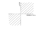
- the displacement in the right direction in FIG. 2 is positive
- the displacement X1 is taken on the vertical axis
- the relative speed d (X1-X2) / dt is taken on the horizontal axis
- the actuator 1 exerts a damping force.
- the first quadrant state and the third quadrant state shown by hatching in FIG. 3 are exhibited.
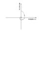
- the apparent rigidity of the actuator 1 is increased, and when the actuator 1 does not exhibit thrust, the apparent rigidity is reduced. Therefore, when the relative displacement between the vibration input side I and the vibration controlled object O is X and the relative speed is dX / dt, and the vibration controlled object O is displaced relative to the vibration input side I, FIG. As shown, the locus converges to the origin on the phase plane between the relative displacement X and the relative velocity dX / dt. That is, it is asymptotically stable and does not diverge.
- the actuator 1 since the actuator 1 is provided with the center passage 16, the actuator 1 does not exhibit thrust that promotes the separation from the neutral position of the piston 3, and the vibration converges. It becomes easy to do. Therefore, it is possible to stably suppress the vibration of the controlled object O.
- the actuator 1 when the actuator 1 is used between a vehicle body and a bogie of a railway vehicle, when the railway vehicle travels in a curved section, steady acceleration acts on the vehicle body due to the effects of noise and drift input to the acceleration sensor. Even if the thrust output by the actuator becomes very large, when the piston 3 passes the neutral position, the thrust that promotes the separation from the neutral position of the piston 3 is not exhibited. In other words, since the vehicle body is not vibrated past the neutral position, the vibration is easily converged and the riding comfort of the railway vehicle is improved.
- the center passage 16 can be switched between the opened state and the blocked state. Therefore, if the center passage 16 is shut off, the actuator 1 can be made to function as a general actuator that exerts thrust in both directions over the entire stroke, and versatility is improved. Further, when necessary, stable vibration suppression can be realized by opening the center passage 16. For example, in the case of low frequency vibration in which vibration with low frequency and high wave height is input, the center passage 16 may be opened to suppress vibration, and vibration suppression is performed as the center passage 16 is opened and closed. There is no need to switch the control mode for.
- the on-off valve 28 since the on-off valve 28 is in the communication position 29a when not energized, the center passage 16 can be opened during a failure to perform stable vibration suppression.
- the on-off valve 28 can be set so as to be in the cutoff position 29b when power supply is impossible.
- resistance can be given to the flow of liquid passing therethrough.
- the opening position of the center passage 16 is the center of the cylinder 2 and the position opposite to the stroke center of the piston 3, the damping when the piston 3 returns to the stroke center. There is no bias in the stroke range where the force is not exerted, and the entire stroke length of the actuator 1 can be used effectively.
- the vibration-suppressed object O and the vibration input side I have been described as the body and carriage of a railway vehicle.
- the present invention is not limited to the railway vehicle, and, for example, approximately vibration such as between a building and the ground.
- the actuator 1 can be used for applications that are used for suppression.
Landscapes
- Engineering & Computer Science (AREA)
- Mechanical Engineering (AREA)
- Physics & Mathematics (AREA)
- Fluid Mechanics (AREA)
- General Engineering & Computer Science (AREA)
- Chemical & Material Sciences (AREA)
- Analytical Chemistry (AREA)
- Fluid-Pressure Circuits (AREA)
- Actuator (AREA)
- Fluid-Damping Devices (AREA)
Abstract
Description
Claims (5)
- アクチュエータであって、
シリンダと、
前記シリンダ内に摺動自在に挿入されるピストンと、
前記シリンダ内に挿入されて前記ピストンに連結されるロッドと、
前記シリンダ内に前記ピストンで区画されるロッド側室およびピストン側室と、
タンクと、
前記ロッド側室へ液体を供給可能な第一ポンプと、
前記ピストン側室へ液体を供給可能な第二ポンプと、
前記ロッド側室と前記タンクとを連通する第一制御通路と、
前記ピストン側室と前記タンクとを連通する第二制御通路と、
前記第一制御通路の途中に設けられ、前記ロッド側室の圧力が開弁圧に達すると開弁して前記ロッド側室から前記タンクへ向かう液体の流れを許容する前記開弁圧を変更可能な第一可変リリーフ弁と、
前記第二制御通路の途中に設けられ、前記ピストン側室の圧力が開弁圧に達すると開弁して前記ピストン側室から前記タンクへ向かう液体の流れを許容する前記開弁圧を変更可能な第二可変リリーフ弁と、
前記タンクと前記シリンダ内とを連通するセンター通路と、
を備えるアクチュエータ。 - 請求項1に記載のアクチュエータであって、
前記第一制御通路の途中に前記第一可変リリーフ弁と並列に設けられ、前記タンクから前記ロッド側室へ向かう液体の通過のみを許容する第一逆止弁と、
前記第二制御通路の途中に前記第二可変リリーフ弁と並列に設けられ、前記タンクから前記ピストン側室へ向かう液体の通過のみを許容する第二逆止弁と、
をさらに備えるアクチュエータ。 - 請求項1に記載のアクチュエータであって、
前記センター通路が、前記シリンダの中央であって、且つ、前記ピストンのストローク中心と対向する位置に開口するアクチュエータ。 - 請求項1に記載のアクチュエータであって、
前記センター通路の途中に、前記センター通路を開閉する開閉弁を設けたアクチュエータ。 - 請求項1に記載のアクチュエータであって、
前記第一ポンプおよび前記第二ポンプは、双方が単一のモータで駆動されるタンデム型ポンプであるアクチュエータ。
Priority Applications (6)
| Application Number | Priority Date | Filing Date | Title |
|---|---|---|---|
| US14/408,573 US9476436B2 (en) | 2012-09-03 | 2013-08-22 | Actuator |
| KR1020147035469A KR101671607B1 (ko) | 2012-09-03 | 2013-08-22 | 액추에이터 |
| EP13832084.1A EP2868931B1 (en) | 2012-09-03 | 2013-08-22 | Actuator |
| CN201380031771.0A CN104379944B (zh) | 2012-09-03 | 2013-08-22 | 致动器 |
| CA2878316A CA2878316C (en) | 2012-09-03 | 2013-08-22 | Actuator |
| ES13832084.1T ES2625478T3 (es) | 2012-09-03 | 2013-08-22 | Actuador |
Applications Claiming Priority (2)
| Application Number | Priority Date | Filing Date | Title |
|---|---|---|---|
| JP2012192754A JP5517368B2 (ja) | 2012-09-03 | 2012-09-03 | アクチュエータ |
| JP2012-192754 | 2012-09-03 |
Publications (1)
| Publication Number | Publication Date |
|---|---|
| WO2014034510A1 true WO2014034510A1 (ja) | 2014-03-06 |
Family
ID=50183325
Family Applications (1)
| Application Number | Title | Priority Date | Filing Date |
|---|---|---|---|
| PCT/JP2013/072361 Ceased WO2014034510A1 (ja) | 2012-09-03 | 2013-08-22 | アクチュエータ |
Country Status (8)
| Country | Link |
|---|---|
| US (1) | US9476436B2 (ja) |
| EP (1) | EP2868931B1 (ja) |
| JP (1) | JP5517368B2 (ja) |
| KR (1) | KR101671607B1 (ja) |
| CN (1) | CN104379944B (ja) |
| CA (1) | CA2878316C (ja) |
| ES (1) | ES2625478T3 (ja) |
| WO (1) | WO2014034510A1 (ja) |
Families Citing this family (26)
| Publication number | Priority date | Publication date | Assignee | Title |
|---|---|---|---|---|
| CN105934582B (zh) * | 2014-02-07 | 2019-04-23 | 杰姆塔布系统公司 | 空气驱动的液压泵 |
| WO2015131196A1 (en) | 2014-02-28 | 2015-09-03 | Project Phoenix, LLC | Pump integrated with two independently driven prime movers |
| WO2015164453A2 (en) | 2014-04-22 | 2015-10-29 | Afshari Thomas | Fluid delivery system with a shaft having a through-passage |
| JP6397220B2 (ja) * | 2014-05-12 | 2018-09-26 | Kyb株式会社 | シリンダ装置 |
| WO2015187681A1 (en) | 2014-06-02 | 2015-12-10 | Afshari Thomas | Hydrostatic transmission assembly and system |
| EP3149342B1 (en) | 2014-06-02 | 2020-04-15 | Project Phoenix LLC | Linear actuator assembly and system |
| KR102316426B1 (ko) | 2014-07-22 | 2021-10-21 | 프로젝트 피닉스, 엘엘씨 | 독립적으로 구동되는 2개의 원동기와 통합된 외부 기어 펌프 |
| US10072676B2 (en) | 2014-09-23 | 2018-09-11 | Project Phoenix, LLC | System to pump fluid and control thereof |
| EP3896314B1 (en) | 2014-10-06 | 2024-03-27 | Project Phoenix, LLC | Linear actuator assembly and system |
| JP6363934B2 (ja) * | 2014-10-17 | 2018-07-25 | Kyb株式会社 | シリンダ装置 |
| US10677352B2 (en) | 2014-10-20 | 2020-06-09 | Project Phoenix, LLC | Hydrostatic transmission assembly and system |
| KR101595117B1 (ko) * | 2015-02-24 | 2016-02-17 | 주식회사 에네스지 | 공기배출유닛 어셈블리 및 이를 갖는 발전소용 복동식 유압액추에이터 |
| KR102328900B1 (ko) * | 2015-04-06 | 2021-11-19 | 현대두산인프라코어(주) | 유압 브레이크 장치 |
| EP3121115B1 (en) * | 2015-07-21 | 2021-09-01 | Airbus Defence and Space GmbH | Coupling device for a wing assembly of an aircraft |
| EP3344853B1 (en) | 2015-09-02 | 2020-11-04 | Project Phoenix LLC | System to pump fluid and control thereof |
| TWI712744B (zh) | 2015-09-02 | 2020-12-11 | 美商鳳凰計劃股份有限公司 | 泵送流體之系統及其控制 |
| CN106286478A (zh) * | 2016-10-08 | 2017-01-04 | 苏州威尔特铝合金升降机械有限公司 | 桅柱式高空作业平台液压缸卸荷装置 |
| CN107806455A (zh) * | 2017-11-21 | 2018-03-16 | 无锡科安自动化装备有限公司 | 食品生产线液压系统用液压缸 |
| US10428845B1 (en) | 2018-03-29 | 2019-10-01 | Sun Hydraulics, Llc | Hydraulic system with a counterbalance valve configured as a meter-out valve and controlled by an independent pilot signal |
| JP6938828B2 (ja) * | 2018-12-28 | 2021-09-22 | Smc株式会社 | 低騒音ゲートバルブ |
| EP4179211A1 (en) | 2020-07-08 | 2023-05-17 | Project Phoenix, LLC | Dynamic control of gears in a gear pump having a drive-drive configuration |
| WO2022011022A1 (en) | 2020-07-08 | 2022-01-13 | Project Phoenix, LLC | Dynamic control of gears in a gear pump having a drive-drive configuration |
| JP7104847B1 (ja) | 2021-04-19 | 2022-07-21 | Kyb株式会社 | ダンパ |
| KR102704482B1 (ko) * | 2021-10-20 | 2024-09-09 | 주식회사 준씨에스 | 승압기를 구비한 유압 실린더 |
| US11619246B1 (en) * | 2022-04-25 | 2023-04-04 | Hamilton Sundstrand Corporation | Fail-fixed hydraulic actuator |
| US12595811B2 (en) * | 2024-04-30 | 2026-04-07 | Rosenboom Machine & Tool, Inc. | Seal plate method for communicating retract oil to retract side of piston in hydraulic cylinder |
Citations (8)
| Publication number | Priority date | Publication date | Assignee | Title |
|---|---|---|---|---|
| JPS5266164A (en) * | 1975-11-29 | 1977-06-01 | Fujikoshi Kk | Electrohydraulic control circuit |
| JPS5910505U (ja) * | 1982-03-15 | 1984-01-23 | エスエムシ−株式会社 | 空気圧シリンダにおけるクツシヨンストロ−クの可変機構 |
| JPH11117907A (ja) * | 1997-10-15 | 1999-04-27 | Tokimec Inc | 液圧源装置を使用した液圧システム |
| JP2001208004A (ja) * | 2000-01-25 | 2001-08-03 | Nireco Corp | 油圧駆動装置 |
| JP2001214903A (ja) * | 2000-02-02 | 2001-08-10 | Kayaba Ind Co Ltd | 油圧式駆動装置 |
| JP2002295413A (ja) * | 2001-03-29 | 2002-10-09 | Fuji Heavy Ind Ltd | 油圧アクチュエータ |
| JP2004510907A (ja) * | 2000-10-05 | 2004-04-08 | ルノー スポール | 弁の作動用の装置及び同装置の制御方法 |
| JP2010065797A (ja) | 2008-09-12 | 2010-03-25 | Kayaba Ind Co Ltd | シリンダ装置 |
Family Cites Families (10)
| Publication number | Priority date | Publication date | Assignee | Title |
|---|---|---|---|---|
| US3465645A (en) * | 1966-09-16 | 1969-09-09 | Renault | Power assisted steering systems of automotive vehicles |
| NL182162C (nl) * | 1977-01-10 | 1988-01-18 | Hydraudyne Bv | Inrichting voor het hydraulisch of pneumatisch aandrijven en afremmen van een werktuig. |
| JP2003042216A (ja) | 2001-07-31 | 2003-02-13 | Tokico Ltd | 油圧ダンパ |
| EP1828618B8 (en) * | 2004-12-01 | 2013-05-08 | Concentric Rockford, Inc | Hydraulic drive system |
| RU2296890C2 (ru) * | 2005-05-05 | 2007-04-10 | Вениамин Яковлевич Вейнберг | Привод для устройства автоматического регулирования |
| CN101357640B (zh) * | 2007-07-30 | 2012-05-23 | 萱场工业株式会社 | 铁道车辆的抑制振动装置 |
| DE202007013300U1 (de) | 2007-09-21 | 2009-02-12 | Liebherr-Aerospace Lindenberg Gmbh | Aktiver hydraulischer Dämpfer und hydraulischer Stellantrieb |
| DE102010011912A1 (de) | 2010-03-18 | 2011-09-22 | Daimler Ag | Gasfederdämpfervorrichtung mit einer Motorgeneratorpumpeneinheit |
| JP5486367B2 (ja) | 2010-03-24 | 2014-05-07 | カヤバ工業株式会社 | アクチュエータユニット |
| CN102588382B (zh) * | 2012-03-19 | 2014-11-26 | 北京航空航天大学 | 一种直接驱动电静液作动器 |
-
2012
- 2012-09-03 JP JP2012192754A patent/JP5517368B2/ja active Active
-
2013
- 2013-08-22 WO PCT/JP2013/072361 patent/WO2014034510A1/ja not_active Ceased
- 2013-08-22 CA CA2878316A patent/CA2878316C/en not_active Expired - Fee Related
- 2013-08-22 CN CN201380031771.0A patent/CN104379944B/zh not_active Expired - Fee Related
- 2013-08-22 EP EP13832084.1A patent/EP2868931B1/en not_active Not-in-force
- 2013-08-22 KR KR1020147035469A patent/KR101671607B1/ko not_active Expired - Fee Related
- 2013-08-22 ES ES13832084.1T patent/ES2625478T3/es active Active
- 2013-08-22 US US14/408,573 patent/US9476436B2/en not_active Expired - Fee Related
Patent Citations (8)
| Publication number | Priority date | Publication date | Assignee | Title |
|---|---|---|---|---|
| JPS5266164A (en) * | 1975-11-29 | 1977-06-01 | Fujikoshi Kk | Electrohydraulic control circuit |
| JPS5910505U (ja) * | 1982-03-15 | 1984-01-23 | エスエムシ−株式会社 | 空気圧シリンダにおけるクツシヨンストロ−クの可変機構 |
| JPH11117907A (ja) * | 1997-10-15 | 1999-04-27 | Tokimec Inc | 液圧源装置を使用した液圧システム |
| JP2001208004A (ja) * | 2000-01-25 | 2001-08-03 | Nireco Corp | 油圧駆動装置 |
| JP2001214903A (ja) * | 2000-02-02 | 2001-08-10 | Kayaba Ind Co Ltd | 油圧式駆動装置 |
| JP2004510907A (ja) * | 2000-10-05 | 2004-04-08 | ルノー スポール | 弁の作動用の装置及び同装置の制御方法 |
| JP2002295413A (ja) * | 2001-03-29 | 2002-10-09 | Fuji Heavy Ind Ltd | 油圧アクチュエータ |
| JP2010065797A (ja) | 2008-09-12 | 2010-03-25 | Kayaba Ind Co Ltd | シリンダ装置 |
Non-Patent Citations (1)
| Title |
|---|
| See also references of EP2868931A4 |
Also Published As
| Publication number | Publication date |
|---|---|
| US9476436B2 (en) | 2016-10-25 |
| CA2878316A1 (en) | 2014-03-06 |
| JP5517368B2 (ja) | 2014-06-11 |
| EP2868931B1 (en) | 2017-04-12 |
| CN104379944B (zh) | 2016-04-13 |
| EP2868931A1 (en) | 2015-05-06 |
| CN104379944A (zh) | 2015-02-25 |
| EP2868931A4 (en) | 2016-03-09 |
| JP2014047876A (ja) | 2014-03-17 |
| US20150184681A1 (en) | 2015-07-02 |
| KR20150015509A (ko) | 2015-02-10 |
| ES2625478T3 (es) | 2017-07-19 |
| CA2878316C (en) | 2017-07-04 |
| KR101671607B1 (ko) | 2016-11-01 |
Similar Documents
| Publication | Publication Date | Title |
|---|---|---|
| WO2014034510A1 (ja) | アクチュエータ | |
| JP5552174B1 (ja) | アクチュエータ | |
| WO2016042996A1 (ja) | 鉄道用制振装置 | |
| JP5564541B2 (ja) | アクチュエータ | |
| JP5572236B1 (ja) | アクチュエータ | |
| JP5608252B2 (ja) | アクチュエータ | |
| JP2011202675A (ja) | アクチュエータユニット | |
| JP5391119B2 (ja) | アクチュエータユニット |
Legal Events
| Date | Code | Title | Description |
|---|---|---|---|
| 121 | Ep: the epo has been informed by wipo that ep was designated in this application |
Ref document number: 13832084 Country of ref document: EP Kind code of ref document: A1 |
|
| ENP | Entry into the national phase |
Ref document number: 20147035469 Country of ref document: KR Kind code of ref document: A |
|
| WWE | Wipo information: entry into national phase |
Ref document number: 14408573 Country of ref document: US |
|
| ENP | Entry into the national phase |
Ref document number: 2878316 Country of ref document: CA |
|
| REEP | Request for entry into the european phase |
Ref document number: 2013832084 Country of ref document: EP |
|
| WWE | Wipo information: entry into national phase |
Ref document number: 2013832084 Country of ref document: EP |
|
| NENP | Non-entry into the national phase |
Ref country code: DE |