WO2014041723A1 - Impact tightening tool - Google Patents
Impact tightening tool Download PDFInfo
- Publication number
- WO2014041723A1 WO2014041723A1 PCT/JP2013/003226 JP2013003226W WO2014041723A1 WO 2014041723 A1 WO2014041723 A1 WO 2014041723A1 JP 2013003226 W JP2013003226 W JP 2013003226W WO 2014041723 A1 WO2014041723 A1 WO 2014041723A1
- Authority
- WO
- WIPO (PCT)
- Prior art keywords
- torque
- value
- angular acceleration
- screw
- output shaft
- Prior art date
- Legal status (The legal status is an assumption and is not a legal conclusion. Google has not performed a legal analysis and makes no representation as to the accuracy of the status listed.)
- Ceased
Links
Images

Classifications
-
- B—PERFORMING OPERATIONS; TRANSPORTING
- B25—HAND TOOLS; PORTABLE POWER-DRIVEN TOOLS; MANIPULATORS
- B25B—TOOLS OR BENCH DEVICES NOT OTHERWISE PROVIDED FOR, FOR FASTENING, CONNECTING, DISENGAGING, OR HOLDING
- B25B23/00—Details of, or accessories for, spanners, wrenches, screwdrivers
- B25B23/14—Arrangement of torque limiters or torque indicators in wrenches or screwdrivers
- B25B23/147—Arrangement of torque limiters or torque indicators in wrenches or screwdrivers specially adapted for electrically operated wrenches or screwdrivers
- B25B23/1475—Arrangement of torque limiters or torque indicators in wrenches or screwdrivers specially adapted for electrically operated wrenches or screwdrivers for impact wrenches or screwdrivers
-
- B—PERFORMING OPERATIONS; TRANSPORTING
- B25—HAND TOOLS; PORTABLE POWER-DRIVEN TOOLS; MANIPULATORS
- B25B—TOOLS OR BENCH DEVICES NOT OTHERWISE PROVIDED FOR, FOR FASTENING, CONNECTING, DISENGAGING, OR HOLDING
- B25B21/00—Portable power-driven screw or nut setting or loosening tools; Attachments for drilling apparatus serving the same purpose
- B25B21/02—Portable power-driven screw or nut setting or loosening tools; Attachments for drilling apparatus serving the same purpose with means for imparting impact to screwdriver blade or nut socket
-
- B—PERFORMING OPERATIONS; TRANSPORTING
- B25—HAND TOOLS; PORTABLE POWER-DRIVEN TOOLS; MANIPULATORS
- B25B—TOOLS OR BENCH DEVICES NOT OTHERWISE PROVIDED FOR, FOR FASTENING, CONNECTING, DISENGAGING, OR HOLDING
- B25B23/00—Details of, or accessories for, spanners, wrenches, screwdrivers
- B25B23/14—Arrangement of torque limiters or torque indicators in wrenches or screwdrivers
- B25B23/145—Arrangement of torque limiters or torque indicators in wrenches or screwdrivers specially adapted for fluid operated wrenches or screwdrivers
- B25B23/1456—Arrangement of torque limiters or torque indicators in wrenches or screwdrivers specially adapted for fluid operated wrenches or screwdrivers having electrical components
Definitions
- the present invention relates to an impact tightening tool to be used for tightening a screw.
- Screws are used for fastening parts together. A screw will loosen if the tightening torque is insufficient and, on the contrary, excessive torque may cause failure of the screw. Therefore, when tightening a screw, it is essential to perform a tightening operation with a proper torque.
- the tightening torque of the tool is determined by acquiring a twist amount (strain amount) of a power transmission shaft with a strain gauge provided in the power transmission shaft, and the motor is stopped when the tightening torque reaches a preset value.
- This is convenient for tightening a screw with a proper torque.
- the operation to paste a strain gauge onto the power transmission shaft is very delicate, it requires skilled work and poses high cost.
- a problem exists in that the tool as a whole increases in size, as well as in weight.
- the tightening torque of the tool is calculated from the inertia of the rotating part including a motor, and the angular acceleration value obtained based on the position sensor information owned by the driving side of the impact tightening generation mechanism.
- the output shaft becomes not to include a strain gauge so that the impact tightening tool becomes reduced in size and weight.
- there exist various losses such as deflection and internal loss in each transmission part due to pulsed tightening torque, and losses caused by the internal inertia of the transmission part itself, and backlashes in joint portions, and thus the technique according to Patent Literature 2 has a problem in that such losses are not taken into consideration.
- actual tightening torque in an impact tightening tool
- e EPSILON
- T(t) Actual torque with which the output shaft tightens a screw
- J*w"(t) Torque generated by the acceleration of the rotating part
- Mt(t) Torque generated by the motor
- e(t) Various loss torques that occur in the transmission system.
- the impact tightening tool according to Patent Literature 2 does not take into account e(t).
- the invention according to claim 1 is an impact tightening tool, including a rotating part, angular acceleration detection means, torque value calculation means, and a storage section, wherein: the rotating part includes a rotary power source, an impact tightening generation mechanism, and an output shaft; the angular acceleration detection means is configured to detect an angular acceleration value of the rotary power source; the torque value calculation means is configured to calculate an actual torque approximate value of the output shaft by using an approximation formula stored in the storage section; and the approximation formula stored in the storage section is a formula which correlates an angular acceleration value detected by the angular acceleration detection means at the time of torque transmission to a screw with an actual torque value of the output shaft at the time of torque transmission to the screw, and is a formula based on a torque measured value of the output shaft measured before the torque transmission to the screw.
- the invention according to claim 2 is the impact tightening tool according to claim 1, wherein the formula based on the torque measured value is derived by substituting an angular acceleration value of the rotary power source measured before the torque transmission to the screw and a torque measured value of the output shaft measured by a torque tester before the torque transmission to the screw into the correlated formula.
- the invention according to claim 3 is an impact tightening tool, including a rotating part, angular acceleration detection means, torque value calculation means, a storage section, and approximation formula derivation means, wherein: the rotating part includes a rotary power source, an impact tightening generation mechanism, and an output shaft; the angular acceleration detection means is configured to detect an angular acceleration value of the rotary power source; the torque value calculation means is configured to calculate an actual torque approximate value of the output shaft by using an approximation formula derived by the approximation formula derivation means; the storage section stores an angular acceleration value of the rotary power source measured before torque transmission to a screw, and a torque measured value of the output shaft measured by a torque tester before the torque transmission to the screw; and the approximation formula derivation means is configured to derive a formula based on the torque measured value of the output shaft measured before the torque transmission to the screw by substituting the angular acceleration value and the torque measured value stored in the storage section into
- the impact tightening tool of the present invention has become an impact tightening tool which enables the calculation of an actual torque approximate value which takes into account the loss caused by actual impact tightening, without an expensive strain gauge provided on the output shaft, thus enabling improved tightening.
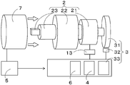
- Fig. 1 shows a partial cross-sectional view and a general side view of an impact tightening tool.
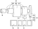
- Fig. 2 is a conceptual diagram of an impact tightening tool performing the measurement of a torque measured value before the torque transmission to a screw.
- Fig. 3 is a conceptual diagram of an impact tightening tool at the time of torque transmission to a screw.
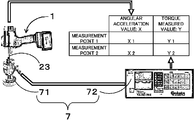
- Fig. 4 is a conceptual diagram showing the measurement of a torque measured value by using a torque tester.
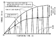
- Fig. 5 is a graph comparing a tightening torque indicated in the conventional art with an actual tightening torque.
- FIG. 1 shows a partial cross-sectional view and a general side view of an impact tightening tool 1.
- Fig. 2 is a conceptual diagram of an impact tightening tool performing the measurement of a torque measured value before the torque transmission to a screw.
- Fig. 3 is a conceptual diagram of an impact tightening tool at the time of torque transmission to a screw.
- Fig. 4 is a conceptual diagram showing the measurement of a torque measured value by using a torque tester.
- Formula 1 shows an example of the formula for calculating an actual torque approximate value T, represented by a first-order equation.
- the impact tightening tool 1 which includes a rotating part 2, angular acceleration detection means 3, torque value calculation means 4, and a storage section 5, is configured to tighten a screw with a preset torque value and include control means 13 for stopping tightening at a preset torque value.
- the impact tightening tool 1 may also include approximation formula derivation means 6.
- the impact tightening tool 1 may include a trigger 11 for performing rotating operation of the rotating part 2, as well as a rotational direction designating lever 12 for designating the rotational direction. To be specific, such impact tightening tool 1 being used is referred to such as an impulse wrench and an impact wrench.
- the impact tightening tool 1 includes at least a calibration mode and a tightening mode.
- the calibration mode is a mode in which storing operation into the storage section 5 is performed
- the tightening mode is a mode in which a screw is tightened with a preset torque.
- the rotating part 2 rotates upon pulling of the trigger 11, and stops upon releasing of the trigger 11.
- the rotating part 2 includes a rotary power source 21, an impact tightening generation mechanism 22, and an output shaft 23.
- the rotary power source 21 may utilize an electric motor, an air motor, and the like.
- the output shaft 23 may be provided with a socket 8 at its front end.
- the angular acceleration detection means 3 is configured to detect an angular acceleration value X of the rotary power source 21.
- the angular acceleration detection means 3 is made up at least of a rotor 31, a sensor 32, and differentiation means 33, as shown in Fig. 2.
- the rotor 31 is connected to the above described rotary power source 21 so as to rotate in tandem.
- the sensor 32 detects a rotational angle THETA of the rotor 31.
- the differentiation means 33 differentiates the detected rotational angle THETA twice to detect an angular acceleration. That is, differentiating rotational angle THETA with respect to time t will result in angular velocity OMEGA, and further differentiating angular velocity OMEGA with respect to time t will result in angular acceleration.
- This value of angular acceleration is an angular acceleration value X.
- the differentiation means 33 for detecting the angular acceleration value X may utilize an arithmetic processing unit to be described later.
- Torque value calculation means 4 The torque value calculation means 4 is configured to calculate an actual torque approximate value T of the output shaft 23 from the angular acceleration value X by using an approximation formula stored in the storage section 5.
- the approximation formula is a formula which correlates the angular acceleration value X detected by the angular acceleration detection means 3 at the time of torque transmission to the screw with the actual torque value of the output shaft 23 at the time of torque transmission to the screw.
- the arithmetic processing unit may be used as the torque value calculation means 4 to calculate an actual torque approximate value T.
- a calculation circuit corresponding to the above described approximation formula may be made up in place of the arithmetic processing unit, to be used as the torque value calculation means 4.
- Torque measured value of output shaft 23 measured before the torque transmission to a screw and an approximation formula Fig. 5 is a graph comparing a tightening torque indicated in the conventional art with an actual tightening torque.
- Formula 1 is an approximation formula, which is based on a torque measured value Y of the output shaft 23 measured before the torque transmission to the screw.
- the torque sensor 71 is attached and fixed to the output shaft 23 of the impact tightening tool 1 so that the torque measured value Y of the output shaft 23 is measured by the torque tester 7 (see Fig. 5).
- the torque tester 7 see Fig. 5
- the angular acceleration values (X1, X2) and the torque measured values (Y1, Y2) are substituted into Formula 1 to derive an approximation formula which is a first-order equation between the angular acceleration value X and the actual torque approximate value T.
- the derived approximation formula of a first-order equation is stored in the storage section 5, and when the storing operation into the storage section 5 is finished, the impact tightening tool 1 is switched from the calibration mode to a tightening mode.
- an actual torque approximate value T is calculated by using the stored approximation formula of a first-order equation based on the angular acceleration value X detected by the angular acceleration detection means 3 at the time of torque transmission to the screw.
- the storage section 5 may be configured to store angular acceleration values (X1, X2) of the rotary power source 21 measured before the torque transmission to the screw, and torque measured values (Y1, Y2) of the output shaft 23 measured by the torque tester 7 before the torque transmission to the screw.
- the impact tightening tool 1 includes approximation formula derivation means 6. In this case as well, when the storing operation into the storage section 5 is finished, the impact tightening tool 1 is switched from the calibration mode to the tightening mode.
- the approximation formula derivation means 6 substitutes "the angular acceleration values (X1, X2) and the torque measured values (Y1, Y2) stored in the storage section 5" into the "formula (Formula 1) which correlates the angular acceleration value X detected by the angular acceleration detection means 3 at the time of torque transmission to the screw with the actual torque value of the output shaft 23 at the time of torque transmission to the screw” to derive a "formula (approximation formula of a first-order equation) based on the torque measured value Y of the output shaft 23 measured before the torque transmission to the screw.”
- the torque value calculation means 4 calculates the actual torque approximate value T of the output shaft 23 by using the approximation formula of a first-order equation derived by the approximation formula derivation means 6 based on the angular acceleration value X detected by the angular acceleration detection means 3 at the time of torque transmission to the screw.
- the storage section 5 stores data such as "the approximation formula of a first-order equation between the angular acceleration value X and the actual torque approximate value T" or "the angular acceleration values (X1, X2) of the rotary power source 21 measured before the torque transmission to the screw, and the torque measured values (Y1, Y2) of the output shaft 23 measured by the torque tester 7 before the torque transmission to the screw.”
- Examples of the storage section 5 storing these data may include a flash memory.
- the impact tightening tool 1 may incorporate a flash memory, and also include an access terminal to the flash memory. The access terminal enables data storage by external electronic devices.
- the impact tightening tool 1 does not need to include an input key which is used in the operation for storing data in the flash memory. This will allow the reduction in size and weight of the impact tightening tool 1.
- the flash memory may be a removable small one, such that it may be removable from the interior of the impact tightening tool 1. By doing so, the removed small flash memory can be mounted to an external electronic device to make the flash memory store the above described data. Then, the small flash memory that has stored the above described data is mounted to the impact tightening tool 1.
- the above described approximation formula of torque will not be limited to Formula 1 and a first-order equation between the angular acceleration value X and the actual torque approximate value T, and can be exemplified by linear approximation, polynomial approximation, power approximation, exponential approximation, log approximation, the spline interpolation, and so on. Then, the number of measurement points may be 2 to n points ([X1, X2, ..., Xn : Y1, Y2, ..., Yn], where n is an arbitrary number) in correspondence with the approximation formula.
- the differentiation means 33, the torque value calculation means 4, the storage section 5 and the approximation formula derivation means 6 can be combined and installed in the impact tightening tool 1 as hardware or software so that the actual torque approximate value T can be calculated by using various mathematical algorithms including the above described methods.
- Patent Laid-Open No. S61-4676 A Patent Literature 2 : Japanese Patent No. 4560268
Landscapes
- Engineering & Computer Science (AREA)
- Mechanical Engineering (AREA)
- Details Of Spanners, Wrenches, And Screw Drivers And Accessories (AREA)
Description
The present invention relates to an impact tightening tool to be used for tightening a screw.
Screws are used for fastening parts together. A screw will loosen if the tightening torque is insufficient and, on the contrary, excessive torque may cause failure of the screw.
Therefore, when tightening a screw, it is essential to perform a tightening operation with a proper torque.
Therefore, when tightening a screw, it is essential to perform a tightening operation with a proper torque.
Nowadays, impact tightening tools which perform tightening of a screw with successive blows are widely used. Upon use of an impact tightening tool, tightening operation is performed such that when a preset tightening torque (proper tightening torque) is reached, the torque transmission to the screw is stopped, thereby maintaining a proper tightening torque.
Implementations of the stopping of torque transmission to the screw may be exemplified by such as one in which a rotary power source (for example, a motor) of the impact tightening tool is stopped or broken, and one in which the torque transmission from the drive source to the screw is disengaged.
Impact tightening tools of this type have been already disclosed in Japanese Patent Laid-Open No. 61-4676 and Japanese Patent No. 4560268. (Patent Literature 1, Patent Literature 2)
Implementations of the stopping of torque transmission to the screw may be exemplified by such as one in which a rotary power source (for example, a motor) of the impact tightening tool is stopped or broken, and one in which the torque transmission from the drive source to the screw is disengaged.
Impact tightening tools of this type have been already disclosed in Japanese Patent Laid-Open No. 61-4676 and Japanese Patent No. 4560268. (
In the technique according to Patent Literature 1, the tightening torque of the tool is determined by acquiring a twist amount (strain amount) of a power transmission shaft with a strain gauge provided in the power transmission shaft, and the motor is stopped when the tightening torque reaches a preset value.
This is convenient for tightening a screw with a proper torque. However, since the operation to paste a strain gauge onto the power transmission shaft is very delicate, it requires skilled work and poses high cost. Moreover, since it requires associated parts, a problem exists in that the tool as a whole increases in size, as well as in weight.
This is convenient for tightening a screw with a proper torque. However, since the operation to paste a strain gauge onto the power transmission shaft is very delicate, it requires skilled work and poses high cost. Moreover, since it requires associated parts, a problem exists in that the tool as a whole increases in size, as well as in weight.
In the technique according to Patent Literature 2, the tightening torque of the tool is calculated from the inertia of the rotating part including a motor, and the angular acceleration value obtained based on the position sensor information owned by the driving side of the impact tightening generation mechanism. According to the technique of Patent Literature 2, the output shaft becomes not to include a strain gauge so that the impact tightening tool becomes reduced in size and weight.
However, in actual impact tightening, there exist various losses such as deflection and internal loss in each transmission part due to pulsed tightening torque, and losses caused by the internal inertia of the transmission part itself, and backlashes in joint portions, and thus the technique according toPatent Literature 2 has a problem in that such losses are not taken into consideration.
However, in actual impact tightening, there exist various losses such as deflection and internal loss in each transmission part due to pulsed tightening torque, and losses caused by the internal inertia of the transmission part itself, and backlashes in joint portions, and thus the technique according to
For example, actual tightening torque (actual torque) in an impact tightening tool can be represented as follows.
T(t) = J*w"(t) + Mt(t) - e(t)
w=OMEGA, e=EPSILON
where,
T(t): Actual torque with which the output shaft tightens a screw,
J*w"(t): Torque generated by the acceleration of the rotating part,
Mt(t): Torque generated by the motor, and
e(t): Various loss torques that occur in the transmission system.
Based on the above described formula, the impact tightening tool according toPatent Literature 2 does not take into account e(t).
Because of this, measure values of torque of the impact tightening tool according toPatent Literature 2 tended to be larger than actual torque values since various loss torques that occur in the transmission system e(t) are not taken into account. As a result of that, the impact tightening tool according to Patent Literature 2 has a problem in that the tightening operation is automatically stopped before a proper tightening torque is reached (the timing of automatic stopping is too early).
T(t) = J*w"(t) + Mt(t) - e(t)
w=OMEGA, e=EPSILON
where,
T(t): Actual torque with which the output shaft tightens a screw,
J*w"(t): Torque generated by the acceleration of the rotating part,
Mt(t): Torque generated by the motor, and
e(t): Various loss torques that occur in the transmission system.
Based on the above described formula, the impact tightening tool according to
Because of this, measure values of torque of the impact tightening tool according to
Accordingly, it is an object of the present invention to provide an impact tightening tool whereby the tool can be stopped at a proper torque by using torque calculation means which takes into account the loss caused by actual impact tightening, without expensive strain gauges provided in the output shaft, thereby enabling improved tightening.
In order to achieve the above described object, the present invention has used the following means.
(The invention according to claim 1)
The invention according toclaim 1 is an impact tightening tool, including a rotating part, angular acceleration detection means, torque value calculation means, and a storage section, wherein: the rotating part includes a rotary power source, an impact tightening generation mechanism, and an output shaft; the angular acceleration detection means is configured to detect an angular acceleration value of the rotary power source; the torque value calculation means is configured to calculate an actual torque approximate value of the output shaft by using an approximation formula stored in the storage section; and the approximation formula stored in the storage section is a formula which correlates an angular acceleration value detected by the angular acceleration detection means at the time of torque transmission to a screw with an actual torque value of the output shaft at the time of torque transmission to the screw, and is a formula based on a torque measured value of the output shaft measured before the torque transmission to the screw.
(The invention according to claim 1)
The invention according to
(The invention according to claim 2)
The invention according toclaim 2 is the impact tightening tool according to claim 1, wherein the formula based on the torque measured value is derived by substituting an angular acceleration value of the rotary power source measured before the torque transmission to the screw and a torque measured value of the output shaft measured by a torque tester before the torque transmission to the screw into the correlated formula.
(The invention according to claim 3)
The invention according toclaim 3 is an impact tightening tool, including a rotating part, angular acceleration detection means, torque value calculation means, a storage section, and approximation formula derivation means, wherein: the rotating part includes a rotary power source, an impact tightening generation mechanism, and an output shaft; the angular acceleration detection means is configured to detect an angular acceleration value of the rotary power source; the torque value calculation means is configured to calculate an actual torque approximate value of the output shaft by using an approximation formula derived by the approximation formula derivation means; the storage section stores an angular acceleration value of the rotary power source measured before torque transmission to a screw, and a torque measured value of the output shaft measured by a torque tester before the torque transmission to the screw; and the approximation formula derivation means is configured to derive a formula based on the torque measured value of the output shaft measured before the torque transmission to the screw by substituting the angular acceleration value and the torque measured value stored in the storage section into a formula which correlates the angular acceleration value detected by the angular acceleration detection means at the time of torque transmission to the screw with the actual torque value of the output shaft at the time of torque transmission to the screw.
The invention according to
(The invention according to claim 3)
The invention according to
Owing to the above described configuration, the impact tightening tool of the present invention has become an impact tightening tool which enables the calculation of an actual torque approximate value which takes into account the loss caused by actual impact tightening, without an expensive strain gauge provided on the output shaft, thus enabling improved tightening. As a result, it is possible to provide a compact, light and inexpensive impact tightening tool.
Hereafter, the impact tightening tool will be described in conjunction with an embodiment shown in each drawing.
1. General configuration of impact tightening tool 1
Fig. 1 shows a partial cross-sectional view and a general side view of animpact tightening tool 1. Fig. 2 is a conceptual diagram of an impact tightening tool performing the measurement of a torque measured value before the torque transmission to a screw. Fig. 3 is a conceptual diagram of an impact tightening tool at the time of torque transmission to a screw. Fig. 4 is a conceptual diagram showing the measurement of a torque measured value by using a torque tester. Formula 1 shows an example of the formula for calculating an actual torque approximate value T, represented by a first-order equation.
Theimpact tightening tool 1, which includes a rotating part 2, angular acceleration detection means 3, torque value calculation means 4, and a storage section 5, is configured to tighten a screw with a preset torque value and include control means 13 for stopping tightening at a preset torque value. The impact tightening tool 1 may also include approximation formula derivation means 6.
Theimpact tightening tool 1 may include a trigger 11 for performing rotating operation of the rotating part 2, as well as a rotational direction designating lever 12 for designating the rotational direction. To be specific, such impact tightening tool 1 being used is referred to such as an impulse wrench and an impact wrench.
Theimpact tightening tool 1 includes at least a calibration mode and a tightening mode. The calibration mode is a mode in which storing operation into the storage section 5 is performed, and the tightening mode is a mode in which a screw is tightened with a preset torque.
Fig. 1 shows a partial cross-sectional view and a general side view of an
The
The
The
2. Rotating part 2
The rotatingpart 2 rotates upon pulling of the trigger 11, and stops upon releasing of the trigger 11.
The rotatingpart 2 includes a rotary power source 21, an impact tightening generation mechanism 22, and an output shaft 23.
Therotary power source 21 may utilize an electric motor, an air motor, and the like. The output shaft 23 may be provided with a socket 8 at its front end.
The rotating
The rotating
The
3. Control of impact tightening tool 1
When tightening a screw with a preset torque value using theimpact tightening tool 1, the following control is performed. Since the tightening torque of a screw increases as it is tightened, the impact tightening tool 1 calculates a current, actual torque approximate value T by using an approximation formula stored in the storage section 5 while tightening the screw. When the above described actual torque approximate value T reaches a preset torque value, the control means 13 stops the rotary power source 21 thereby terminating tightening. Alternatively, upon the preset torque value being reached, the control means 13 signals the operator with such as sound and light to release the trigger 11. The confirmation that the preset torque value is reached is performed when the actual torque approximate value T exceeds the preset torque value.
When tightening a screw with a preset torque value using the
4. Angular acceleration detection means 3
The angular acceleration detection means 3 is configured to detect an angular acceleration value X of therotary power source 21.
The angular acceleration detection means 3 is made up at least of arotor 31, a sensor 32, and differentiation means 33, as shown in Fig. 2. The rotor 31 is connected to the above described rotary power source 21 so as to rotate in tandem. The sensor 32 detects a rotational angle THETA of the rotor 31. The differentiation means 33 differentiates the detected rotational angle THETA twice to detect an angular acceleration. That is, differentiating rotational angle THETA with respect to time t will result in angular velocity OMEGA, and further differentiating angular velocity OMEGA with respect to time t will result in angular acceleration. This value of angular acceleration is an angular acceleration value X.
The differentiation means 33 for detecting the angular acceleration value X may utilize an arithmetic processing unit to be described later.
The angular acceleration detection means 3 is configured to detect an angular acceleration value X of the
The angular acceleration detection means 3 is made up at least of a
The differentiation means 33 for detecting the angular acceleration value X may utilize an arithmetic processing unit to be described later.
5. Torque value calculation means 4
The torque value calculation means 4 is configured to calculate an actual torque approximate value T of theoutput shaft 23 from the angular acceleration value X by using an approximation formula stored in the storage section 5. The approximation formula is a formula which correlates the angular acceleration value X detected by the angular acceleration detection means 3 at the time of torque transmission to the screw with the actual torque value of the output shaft 23 at the time of torque transmission to the screw. In an implementation in which the impact tightening tool 1 is provided with an arithmetic processing unit, the arithmetic processing unit may be used as the torque value calculation means 4 to calculate an actual torque approximate value T. Moreover, a calculation circuit corresponding to the above described approximation formula may be made up in place of the arithmetic processing unit, to be used as the torque value calculation means 4.
The torque value calculation means 4 is configured to calculate an actual torque approximate value T of the
6. Torque measured value of output shaft 23 measured before the torque transmission to a screw and an approximation formula
Fig. 5 is a graph comparing a tightening torque indicated in the conventional art with an actual tightening torque.
Formula 1 is an approximation formula, which is based on a torque measured value Y of the output shaft 23 measured before the torque transmission to the screw.
Fig. 5 is a graph comparing a tightening torque indicated in the conventional art with an actual tightening torque.

Description will be made, as an example, on a case in which as a formula based on the torque measured value Y of the output shaft 23 measured before the torque transmission to the screw, an approximation formula of a first-order equation is derived by substituting angular acceleration values (X1, X2) of the rotary power source 21 measured before the torque transmission to the screw, and torque measured values (Y1, Y2) of the output shaft 23 measured by the torque tester 7 before the torque transmission to the screw into Formula 1.
First, as shown in Fig. 4, atorque tester 7 having a torque sensor 71 and a torque indicator 72 is prepared. Next, the impact tightening tool 1 is activated in a preprogrammed calibration mode. Then, the torque sensor 71 is attached and fixed to the output shaft 23 of the impact tightening tool 1 so that the torque measured value Y of the output shaft 23 is measured by the torque tester 7 (see Fig. 5). When there are two measurement points, it is possible to obtain a torque measured value Y1 when the angular acceleration value is X1, and a torque measured value Y2 when the angular acceleration value is X2.
Then, the angular acceleration values (X1, X2) and the torque measured values (Y1, Y2) are substituted intoFormula 1 to derive an approximation formula which is a first-order equation between the angular acceleration value X and the actual torque approximate value T. The derived approximation formula of a first-order equation is stored in the storage section 5, and when the storing operation into the storage section 5 is finished, the impact tightening tool 1 is switched from the calibration mode to a tightening mode. At the time of torque transmission to the screw, an actual torque approximate value T is calculated by using the stored approximation formula of a first-order equation based on the angular acceleration value X detected by the angular acceleration detection means 3 at the time of torque transmission to the screw.
First, as shown in Fig. 4, a
Then, the angular acceleration values (X1, X2) and the torque measured values (Y1, Y2) are substituted into
7. Implementation in which storage section 5 stores angular acceleration values and torque measured values
Further, thestorage section 5 may be configured to store angular acceleration values (X1, X2) of the rotary power source 21 measured before the torque transmission to the screw, and torque measured values (Y1, Y2) of the output shaft 23 measured by the torque tester 7 before the torque transmission to the screw.
When thestorage section 5 stores the angular acceleration values (X1, X2) and the torque measured values (Y1, Y2), the impact tightening tool 1 includes approximation formula derivation means 6. In this case as well, when the storing operation into the storage section 5 is finished, the impact tightening tool 1 is switched from the calibration mode to the tightening mode.
Then, the approximation formula derivation means 6 substitutes "the angular acceleration values (X1, X2) and the torque measured values (Y1, Y2) stored in thestorage section 5" into the "formula (Formula 1) which correlates the angular acceleration value X detected by the angular acceleration detection means 3 at the time of torque transmission to the screw with the actual torque value of the output shaft 23 at the time of torque transmission to the screw" to derive a "formula (approximation formula of a first-order equation) based on the torque measured value Y of the output shaft 23 measured before the torque transmission to the screw."
Then, at the time of torque transmission to the screw, the torque value calculation means 4 calculates the actual torque approximate value T of theoutput shaft 23 by using the approximation formula of a first-order equation derived by the approximation formula derivation means 6 based on the angular acceleration value X detected by the angular acceleration detection means 3 at the time of torque transmission to the screw.
Further, the
When the
Then, the approximation formula derivation means 6 substitutes "the angular acceleration values (X1, X2) and the torque measured values (Y1, Y2) stored in the
Then, at the time of torque transmission to the screw, the torque value calculation means 4 calculates the actual torque approximate value T of the
8. Data storage of storage section 5
As described so far, thestorage section 5 stores data such as "the approximation formula of a first-order equation between the angular acceleration value X and the actual torque approximate value T" or "the angular acceleration values (X1, X2) of the rotary power source 21 measured before the torque transmission to the screw, and the torque measured values (Y1, Y2) of the output shaft 23 measured by the torque tester 7 before the torque transmission to the screw." Examples of the storage section 5 storing these data may include a flash memory.
Then, theimpact tightening tool 1 may incorporate a flash memory, and also include an access terminal to the flash memory. The access terminal enables data storage by external electronic devices.
In this way, theimpact tightening tool 1 does not need to include an input key which is used in the operation for storing data in the flash memory. This will allow the reduction in size and weight of the impact tightening tool 1.
Further, the flash memory may be a removable small one, such that it may be removable from the interior of theimpact tightening tool 1. By doing so, the removed small flash memory can be mounted to an external electronic device to make the flash memory store the above described data. Then, the small flash memory that has stored the above described data is mounted to the impact tightening tool 1.
As described so far, the
Then, the
In this way, the
Further, the flash memory may be a removable small one, such that it may be removable from the interior of the
9. Other approximation formulas
The above described approximation formula of torque will not be limited toFormula 1 and a first-order equation between the angular acceleration value X and the actual torque approximate value T, and can be exemplified by linear approximation, polynomial approximation, power approximation, exponential approximation, log approximation, the spline interpolation, and so on. Then, the number of measurement points may be 2 to n points ([X1, X2, ..., Xn : Y1, Y2, ..., Yn], where n is an arbitrary number) in correspondence with the approximation formula. Further, the differentiation means 33, the torque value calculation means 4, the storage section 5 and the approximation formula derivation means 6 can be combined and installed in the impact tightening tool 1 as hardware or software so that the actual torque approximate value T can be calculated by using various mathematical algorithms including the above described methods.
The above described approximation formula of torque will not be limited to
10. Effect of the impact tightening tool 1 which adopts the above described actual torque approximate value T
As a result of usingFormula 1 or the first-order equation between the angular acceleration value X and the actual torque approximate value T, the calculated actual torque approximate value T becomes close to the torque measured value Y shown in Fig. 5 so that the impact tightening tool 1 enables better torque management.
As a result of obviating the need for a strain gauge which is conventionally needed for good torque management, theimpact tightening tool 1 becomes reduced in size and weight, and moreover inexpensive, even though it can obtain a relatively accurate actual torque approximate value T.
As a result of using
As a result of obviating the need for a strain gauge which is conventionally needed for good torque management, the
It is assumed that the above described actual torque approximate value T be used for impact tightening tools 1 such as air impact wrenches, air impulse wrenches, power impact wrenches, power impulse wrenches, and so on.
It can also be applied to other tools which provide successive blows.
It can also be applied to other tools which provide successive blows.
1.impact tightening tool
11.trigger
12.rotational direction designating lever
13.control means
2.rotating part
21.rotary power source
22.impact tightening generation mechanism
23.output shaft
3 .angular acceleration detection means
31.rotor
32.sensor
33.differentiation means
4.torque value calculation means
5.storage section
6.approximation formula derivation means
7.torque tester
71.torque sensor
72.torque indicator
8.socket
11.trigger
12.rotational direction designating lever
13.control means
2.rotating part
21.rotary power source
22.impact tightening generation mechanism
23.output shaft
3 .angular acceleration detection means
31.rotor
32.sensor
33.differentiation means
4.torque value calculation means
5.storage section
6.approximation formula derivation means
7.torque tester
71.torque sensor
72.torque indicator
8.socket
Claims (3)
-
An impact tightening tool (1), comprising a rotating part (2), angular acceleration detection means (3), torque value calculation means (4), and a storage section (5), wherein:
the rotating part (2) includes a rotary power source (21), an impact tightening generation mechanism (22), and an output shaft (23);
the angular acceleration detection means (3) is configured to detect an angular acceleration value of the rotary power source (21);
the torque value calculation means (4) is configured to calculate an actual torque approximate value of the output shaft (23) by using an approximation formula stored in the storage section (5); and
the approximation formula stored in the storage section (5) is a formula which correlates an angular acceleration value detected by the angular acceleration detection means (3) at the time of torque transmission to a screw with an actual torque value of the output shaft (23) at the time of torque transmission to the screw, and is a formula based on a torque measured value of the output shaft (23) measured before the torque transmission to the screw. - The impact tightening tool according to claim 1, wherein
the formula based on the torque measured value is derived by substituting an angular acceleration value of the rotary power source (21) measured before the torque transmission to the screw and a torque measured value of the output shaft (23) measured by a torque tester (7) before the torque transmission to the screw into the correlated formula. - An impact tightening tool (1), comprising a rotating part (2), angular acceleration detection means (3), torque value calculation means (4), a storage section (5), and approximation formula derivation means (6), wherein:
the rotating part (2) includes a rotary power source (21), an impact tightening generation mechanism (22), and an output shaft (23);
the angular acceleration detection means (3) is configured to detect an angular acceleration value of the rotary power source (21);
the torque value calculation means (4) is configured to calculate an actual torque approximate value of the output shaft (23) by using an approximation formula derived by the approximation formula derivation means (6);
the storage section (5) stores an angular acceleration value of the rotary power source (21) measured before torque transmission to a screw, and a torque measured value of the output shaft (23) measured by a torque tester (7) before the torque transmission to the screw; and
the approximation formula derivation means (6) is configured to derive a formula based on the torque measured value of the output shaft (23) measured before the torque transmission to the screw by substituting the angular acceleration value and the torque measured value stored in the storage section (5) into a formula which correlates the angular acceleration value detected by the angular acceleration detection means (3) at the time of torque transmission to the screw with the actual torque value of the output shaft (23) at the time of torque transmission to the screw.
Priority Applications (1)
| Application Number | Priority Date | Filing Date | Title |
|---|---|---|---|
| EP13786144.9A EP2895300B1 (en) | 2012-09-13 | 2013-05-21 | Impact tightening tool |
Applications Claiming Priority (2)
| Application Number | Priority Date | Filing Date | Title |
|---|---|---|---|
| JP2012-201414 | 2012-09-13 | ||
| JP2012201414A JP5877468B2 (en) | 2012-09-13 | 2012-09-13 | Impact tightening tool |
Publications (1)
| Publication Number | Publication Date |
|---|---|
| WO2014041723A1 true WO2014041723A1 (en) | 2014-03-20 |
Family
ID=50277870
Family Applications (1)
| Application Number | Title | Priority Date | Filing Date |
|---|---|---|---|
| PCT/JP2013/003226 Ceased WO2014041723A1 (en) | 2012-09-13 | 2013-05-21 | Impact tightening tool |
Country Status (3)
| Country | Link |
|---|---|
| EP (1) | EP2895300B1 (en) |
| JP (1) | JP5877468B2 (en) |
| WO (1) | WO2014041723A1 (en) |
Cited By (1)
| Publication number | Priority date | Publication date | Assignee | Title |
|---|---|---|---|---|
| WO2021167668A1 (en) * | 2020-02-17 | 2021-08-26 | Apex Brands, Inc. | Automatic torque calibration |
Families Citing this family (5)
| Publication number | Priority date | Publication date | Assignee | Title |
|---|---|---|---|---|
| JP6135925B2 (en) * | 2013-07-19 | 2017-05-31 | パナソニックIpマネジメント株式会社 | Impact rotary tool and tip attachment for impact rotary tool |
| JP6395075B2 (en) * | 2014-03-31 | 2018-09-26 | パナソニックIpマネジメント株式会社 | Attachment for impact tool and impact tool |
| JP6917453B2 (en) * | 2016-11-21 | 2021-08-11 | 厚 飛 胡 | How to protect the high-speed rotary wrench and the motor used for the high-speed rotary wrench |
| JP6984082B2 (en) * | 2017-08-25 | 2021-12-17 | 京都機械工具株式会社 | Driver unit |
| CN109465630A (en) * | 2018-12-21 | 2019-03-15 | 南京林城亿轮轨道交通技术有限公司 | A kind of intelligence torque operation supervisory systems and control method |
Citations (4)
| Publication number | Priority date | Publication date | Assignee | Title |
|---|---|---|---|---|
| JPS58217278A (en) * | 1982-05-26 | 1983-12-17 | レジ−・ナシヨナル・デ・ユジ−ヌ・ルノ− | Clamping of assembly having assembling element with screw |
| JPS614676A (en) | 1984-06-15 | 1986-01-10 | ヨコタ工業株式会社 | Controller for clamping torque of impulse wrench |
| JPH0435878A (en) * | 1990-05-31 | 1992-02-06 | Matsushita Electric Works Ltd | Motor driver |
| WO2002083366A1 (en) * | 2001-04-17 | 2002-10-24 | Atlas Copco Tools Ab | Method and device for determining the torque applied to the fastener as a function of the retardation and te inertia moment |
Family Cites Families (2)
| Publication number | Priority date | Publication date | Assignee | Title |
|---|---|---|---|---|
| JP2007167959A (en) * | 2003-06-25 | 2007-07-05 | 株式会社空研 | Screw tightening control method and impact power screw tightening tool |
| JP2005212022A (en) * | 2004-01-29 | 2005-08-11 | Yokota Kogyo Kk | Impact fastening tool |
-
2012
- 2012-09-13 JP JP2012201414A patent/JP5877468B2/en active Active
-
2013
- 2013-05-21 WO PCT/JP2013/003226 patent/WO2014041723A1/en not_active Ceased
- 2013-05-21 EP EP13786144.9A patent/EP2895300B1/en active Active
Patent Citations (5)
| Publication number | Priority date | Publication date | Assignee | Title |
|---|---|---|---|---|
| JPS58217278A (en) * | 1982-05-26 | 1983-12-17 | レジ−・ナシヨナル・デ・ユジ−ヌ・ルノ− | Clamping of assembly having assembling element with screw |
| JPS614676A (en) | 1984-06-15 | 1986-01-10 | ヨコタ工業株式会社 | Controller for clamping torque of impulse wrench |
| JPH0435878A (en) * | 1990-05-31 | 1992-02-06 | Matsushita Electric Works Ltd | Motor driver |
| WO2002083366A1 (en) * | 2001-04-17 | 2002-10-24 | Atlas Copco Tools Ab | Method and device for determining the torque applied to the fastener as a function of the retardation and te inertia moment |
| JP4560268B2 (en) | 2001-04-17 | 2010-10-13 | アトラス・コプコ・ツールス・アクチボラグ | Method and apparatus for measuring torque supplied to a part as a function of deceleration and moment of inertia and impact tool system |
Cited By (2)
| Publication number | Priority date | Publication date | Assignee | Title |
|---|---|---|---|---|
| WO2021167668A1 (en) * | 2020-02-17 | 2021-08-26 | Apex Brands, Inc. | Automatic torque calibration |
| US11768124B2 (en) | 2020-02-17 | 2023-09-26 | Apex Brands, Inc. | Automatic torque calibration |
Also Published As
| Publication number | Publication date |
|---|---|
| EP2895300B1 (en) | 2018-04-04 |
| EP2895300A4 (en) | 2016-06-08 |
| JP2014054702A (en) | 2014-03-27 |
| EP2895300A1 (en) | 2015-07-22 |
| JP5877468B2 (en) | 2016-03-08 |
Similar Documents
| Publication | Publication Date | Title |
|---|---|---|
| WO2014041723A1 (en) | Impact tightening tool | |
| KR102547472B1 (en) | pulsed tool | |
| CN112533731B (en) | Tightening device, driving torque generating device, tightening system, and torque control method | |
| JPH06210574A (en) | Method and device for monitoring rotating angle and for tightening or loosening thread connector | |
| JP7275008B2 (en) | Diagnostic device, motor drive device and diagnostic method | |
| KR102623683B1 (en) | electric pulse tool | |
| WO2018100802A1 (en) | Rotary impact tool | |
| JP5687539B2 (en) | Impact tools | |
| JP2009083002A (en) | Impact rotary tool | |
| CN110325323B (en) | Electric pulse tool | |
| JPH09285974A (en) | Impact wrench fastening controlling method and device thereof | |
| US10668603B2 (en) | Impulse wrench rotation detection | |
| JP2005279865A (en) | Impact type fastening tool | |
| JPH08267368A (en) | Torque control type pulse tool | |
| JP2013107165A (en) | Impact rotary tool | |
| US20230271306A1 (en) | Impact rotary tool, torque calculation method, and program | |
| JP6664102B2 (en) | How to set impact rotary tool and shut-off impact number | |
| JP2002127032A (en) | Impact rotary tool | |
| JP2009262273A (en) | Impact rotary tool | |
| JPH08267369A (en) | Torque control type pulse tool | |
| KR102774527B1 (en) | Hand held electric pulse tool and a method for tightening operations | |
| KR102505813B1 (en) | Apparatus and method for correcting electrical angle of motor | |
| JP7220362B2 (en) | Electric tool | |
| WO2026068125A1 (en) | Pulse tool for tightening joints | |
| JP2005212022A (en) | Impact fastening tool |
Legal Events
| Date | Code | Title | Description |
|---|---|---|---|
| 121 | Ep: the epo has been informed by wipo that ep was designated in this application |
Ref document number: 13786144 Country of ref document: EP Kind code of ref document: A1 |
|
| NENP | Non-entry into the national phase |
Ref country code: DE |