WO2014041748A1 - スイッチ - Google Patents
スイッチ Download PDFInfo
- Publication number
- WO2014041748A1 WO2014041748A1 PCT/JP2013/004921 JP2013004921W WO2014041748A1 WO 2014041748 A1 WO2014041748 A1 WO 2014041748A1 JP 2013004921 W JP2013004921 W JP 2013004921W WO 2014041748 A1 WO2014041748 A1 WO 2014041748A1
- Authority
- WO
- WIPO (PCT)
- Prior art keywords
- plate
- terminal
- switch
- main body
- switch body
- Prior art date
- Legal status (The legal status is an assumption and is not a legal conclusion. Google has not performed a legal analysis and makes no representation as to the accuracy of the status listed.)
- Ceased
Links
Images


Classifications
-
- H—ELECTRICITY
- H01—ELECTRIC ELEMENTS
- H01H—ELECTRIC SWITCHES; RELAYS; SELECTORS; EMERGENCY PROTECTIVE DEVICES
- H01H23/00—Tumbler or rocker switches, i.e. switches characterised by being operated by rocking an operating member in the form of a rocker button
- H01H23/02—Details
- H01H23/12—Movable parts; Contacts mounted thereon
- H01H23/14—Tumblers
- H01H23/143—Tumblers having a generally flat elongated shape
-
- H—ELECTRICITY
- H01—ELECTRIC ELEMENTS
- H01H—ELECTRIC SWITCHES; RELAYS; SELECTORS; EMERGENCY PROTECTIVE DEVICES
- H01H23/00—Tumbler or rocker switches, i.e. switches characterised by being operated by rocking an operating member in the form of a rocker button
- H01H23/02—Details
- H01H23/12—Movable parts; Contacts mounted thereon
- H01H23/16—Driving mechanisms
- H01H23/20—Driving mechanisms having snap action
- H01H23/205—Driving mechanisms having snap action using a compression spring between tumbler and an articulated contact plate
-
- H—ELECTRICITY
- H01—ELECTRIC ELEMENTS
- H01H—ELECTRIC SWITCHES; RELAYS; SELECTORS; EMERGENCY PROTECTIVE DEVICES
- H01H23/00—Tumbler or rocker switches, i.e. switches characterised by being operated by rocking an operating member in the form of a rocker button
- H01H23/02—Details
- H01H23/04—Cases; Covers
Definitions
- the present invention relates to a switch.
- a switch body embedded in an embedding hole provided in a wall material and an insertion hole through which the switch body is inserted are detachably coupled to the switch body and fixed to the wall material.
- an object of the present invention is to provide a switch that can reduce maintenance costs when the switch body is repeatedly attached to and detached from the plate.
- the switch of the present invention has a switch body embedded in an embedding hole provided in a wall material, and an insertion hole through which the switch body is inserted, and is detachably coupled to the switch body and the wall.
- a plate fixed to the material, and the switch body and the plate are coupled to each other with an engaging projection provided on a portion of the plate facing each other across the switch body. It is achieved by engaging in the engagement hole formed.
- the engagement convex portion which is relatively easily damaged when the switch body is repeatedly attached to and detached from the plate, is provided on the plate whose unit price is generally lower than that of the switch body. Maintenance costs can be reduced compared to the case where the convex portion is provided on the switch body side.
- FIG. 1 It is a perspective view which shows the plate and switch main body in the switch which concern on embodiment of this invention. It is a disassembled perspective view which shows the switch which concerns on embodiment of this invention. It is the perspective view seen from the front side which shows the switch concerning the embodiment of the present invention. It is the perspective view seen from the back side which shows the switch which concerns on embodiment of this invention. It is sectional drawing which shows the principal part in the state by which the terminal screw was loosened in the switch which concerns on embodiment of this invention. It is sectional drawing which shows the switch which concerns on embodiment of this invention. It is a perspective view which shows the plate and switch main body in the conventional switch. It is sectional drawing which shows the plate and switch main body in the conventional switch.
- the switch of this embodiment is shown in FIGS.
- the vertical direction coincides with the axial direction of the terminal screw 44 described later
- the upward direction (A direction) indicates the moving direction of the first terminal nut 431 when the first terminal screw 451 described later is tightened.
- the first direction the downward direction (the B direction) is the opposite direction to the first direction, and the moving direction of the second terminal nut 432 when a second terminal screw 452 to be described later is tightened ( (Second direction).
- the left-right direction is a direction orthogonal to the first direction and parallel to the surface of the plate 21, and the left direction (C direction) is the left direction (third direction) when the switch is viewed from the front.
- the right direction (D direction) is the opposite direction to the third direction, and is the right direction (fourth direction) when the switch is viewed from the front.
- the front-rear direction is a direction orthogonal to the first direction and the third direction
- the front direction (E direction) is a direction in which the electric wire is inserted into first and second electric wire insertion holes 531 and 532 (to be described later)
- the fifth direction) is the opposite direction to the fifth direction, and is a pressing direction (sixth direction) to the operation handle 31 described later.
- This switch includes a switch body 1 and a plate 21 and two mounting brackets 22 used when the switch body 1 is embedded in an embedding hole (not shown) provided in a wall material.
- the switch body 1 includes a reversing handle 32 that swings in response to an operating force via an operating handle 31 and a contact 40 that has a movable contact 401 and swings in conjunction with the reversing handle 32. Further, the switch body 1 includes a first terminal plate 41 having a fulcrum convex portion 411 serving as a fulcrum of the contact 40, and a second terminal plate 42 provided with a fixed contact 421 to which the movable contact 401 of the contact 40 is separated. Is provided.
- the reversing handle 32 is made of, for example, synthetic resin, and the contactor 40 and the first and second terminal plates 41, 42 are each made of, for example, a metal plate.
- the switch body 1 includes a housing 5 composed of a casing 51 and a cover 52.
- the casing 51 has an open front surface, and thereby the storage recess 50 in which the contact 40 and the first and second terminal plates 41 and 42 are stored, respectively, is disposed.
- the cover 52 is coupled to the front side of the casing 51 and serves as a fulcrum for the reversing handle 32.
- the casing 51 and the cover 52 are each made of synthetic resin, for example.
- central convex portions 511 and 511 project from the central portion in the vertical direction (first and second directions), and two on each of the upper and lower sides of each central convex portion 511.
- the connecting projections 512 and 512 are projected.
- the cover 52 includes a frame-shaped main body 520 surrounding the reversing handle 32 and four coupling pieces 521 projecting rearward. Two of the four coupling pieces 521 are arranged in the vertical direction at the right end portion of the main body portion 520, and the remaining coupling pieces 521 are arranged in the vertical direction at the left end portion of the main body portion 520.
- Each coupling piece 521 has a plate shape whose thickness direction is directed in the left-right direction (third and fourth directions), and a coupling hole 522 into which each coupling projection 512 is engaged penetrates in the left-right direction. Has been.
- the two coupling pieces 521 and 521 sandwich the central convex portion 511, and the coupling convex portion 512 is inserted into each coupling hole 522, whereby the casing 51 and the cover 52 Bind to each other. Further, at the time of engaging / disengaging the coupling convex portion 512 with respect to the coupling hole 522, the coupling piece 521 is elastically deformed so as to displace the front end portion (rear end portion) outward in the left-right direction with respect to the base portion (front end portion).
- the reversing handle 32 has a cuboid-shaped main body 320 as a whole, and two fulcrum convex portions 321 and 321 respectively protruding outward in the left-right direction from the left and right sides of the main body 320. Further, the cover 52 has two fulcrum receiving portions 523 and 523 that protrude forward at the left and right ends of the main body 520. Each of the fulcrum receiving portions 523 and 523 has a concave portion formed on an inward surface in the left-right direction.
- the reversing handle 32 displaces both upper and lower end portions in the front-rear direction (fifth and sixth directions) with respect to the central portion by causing each fulcrum convex portion 321 to contact the front end portion of the fulcrum receiving portion 523 from the rear. Thus, it can swing with respect to the cover 52.
- a fitting recess 310 (see FIG. 6) into which the front end portion of the reversing handle 32 is fitted is provided on the rear surface of the operation handle 31.
- Two engaging convex portions 322 and 322 are respectively provided on the upper and lower surfaces of the reversing handle 32, and each engaging convex portion 322 is provided on each of the upper and lower sides on the inner peripheral surface of the fitting concave portion 310.
- the operating handle 31 is integrated with the reversing handle 32 by engaging with the two engaging recesses 312 and 312 respectively.
- the switch body 1 is provided with a reversing spring 33 which is formed of a coil spring and has one end elastically contacting the rear end of the reversing handle 32 and the other end elastically contacting the front surface of the contact 40.
- a reversing spring 33 which is formed of a coil spring and has one end elastically contacting the rear end of the reversing handle 32 and the other end elastically contacting the front surface of the contact 40.
- FIG. 5 only both end portions of the reversing spring 33 are shown. Due to the spring force of the reversing spring 33, each fulcrum convex part 321 of the reversing handle 32 is pressed against the fulcrum receiving part 523 of the cover 52 from the rear, and the contact 40 is pressed against the fulcrum convex part 411 of the first terminal plate 41 from the front. It is done.
- a reversing spring. 33 bends so that the central part is positioned above both ends in the vertical direction.
- the spring force of the reversing spring 33 acts on the reversing handle 32 so that the posture of the reversing handle 32 is maintained.
- the contact 40 the movable contact 401 is provided downward, and in the second contact plate 42, the fixed contact 421 is provided upward.
- the spring force of the reversing spring 33 acts on the contact 40 so as to keep the movable contact 401 away from the fixed contact 421. That is, in the off state, the first terminal plate 41 and the second terminal plate 42 are not electrically connected.
- the upper end portion of the reversing handle 32 receives a backward pressing force via the operation handle 31, and the reversing handle 32 resists the spring force of the reversing spring 33 and rotates clockwise as viewed from the right.
- the direction of the spring force of the reversing spring 33 is reversed when the lower end of the reversing handle 32 is displaced to the front side of the central portion.
- the reversing handle 32 is displaced at a stretch by the spring force of the reversing spring 33 into a state in which the lower end protrudes forward of the housing 5 (hereinafter referred to as “on state”).
- ON state as shown in FIG.
- the reversing spring 33 bends so that the center portion is positioned below the both end portions in the vertical direction, and the spring force of the reversing spring 33 is the movable contact 401 with respect to the contact 40. Is pressed against the fixed contact 421. That is, in the ON state, the first terminal plate 41 and the second terminal plate 42 are electrically connected to each other via the contact 40.
- a mark 311 made of a convex portion is attached to an upper end portion that is pushed backward in the ON state.
- the mark 311 is not restricted to a convex part, You may attach
- the reversing handle 32 In the ON state, when the lower end portion of the reversing handle 32 receives a backward pressing force via the operation handle 31 and rotates counterclockwise as viewed from the right against the spring force of the reversing spring 33, the reversing handle When the upper end portion of 32 is displaced to the front side of the central portion, the direction of the spring force of the reversing spring 33 is reversed, and the reversing handle 32 is displaced to the off state at once.
- first terminal nuts 431 and first terminal screws 451 for the first terminal plate 41, and second terminals.
- a set of terminal nuts 43 and terminal screws 44 for the plate 42 are accommodated.
- An electric wire is connected to the first and second terminal plates 41 and 42 via the first terminal nut 431 and the first terminal screw 451 and the second terminal nut 432 and the second terminal screw 452.
- the first terminal plate 41 has a first contact portion 412 that is inserted between the head 441 of the first terminal screw 451 and the first terminal nut 431 and faces the first terminal nut 431.
- the second terminal plate 42 has a second contact portion 422 that is inserted between the head 441 of the second terminal screw 452 and the second terminal nut 432 and faces the second terminal nut 432.
- the first and second contact portions 412 and 422 are U-shaped having cutout portions 413 and 423 that avoid the shaft portions 442 of the first and second terminal screws 451 and 452, respectively.
- the positioning recess 56 of the casing 51 is provided with four positioning grooves 56 on the inner peripheral surface thereof. Two of them are provided so as to correspond to the first terminal plate 41, are formed on the left inner surface and the right inner surface so as to face each other, and the remaining grooves 56 are provided so as to correspond to the second terminal plate 42.
- first and second terminal plates 41 and 42 are rattled against the housing 5 by inserting the left and right end portions of the first and second contact portions 412 and 422 into the corresponding positioning grooves 56, respectively. Is suppressed.
- first and second terminal screws 451 and 452 are respectively stored in the upper and lower ends of the storage recess 50 with the axial direction facing the vertical direction and the head 441 facing the outer side in the vertical direction. ing.
- a pair of first electric wire insertion holes 531 and 531 which are through holes penetrating in the front-rear direction and a pair of second electric wire insertion holes 532 are formed on the bottom surface of the housing recess 50 of the casing 51. , 532 are provided.
- the first electric wire insertion holes 531 and 531 are provided above the housing recess 50 so as to correspond to the first terminal plate 41, and the second electric wire insertion holes 532 and 532 correspond to the second terminal plate 42. Is provided below the storage recess 50.
- the first electric wire insertion holes 531 and 531 are disposed slightly below the first contact portion 412 of the first terminal plate 41.
- the first wire insertion holes 531 and 531 are arranged such that the shaft portion 442 of the first terminal screw 451 is located between the holes 531 and 531 when viewed from the front-rear direction.
- the second wire insertion holes 532 and 532 are arranged slightly above the second contact portion 422 of the second terminal plate 42.
- the second wire insertion holes 532 and 532 are arranged such that the shaft portion 442 of the second terminal screw 452 is located between the holes 532 and 532 when viewed from the front-rear direction.
- first and second screw operation holes 541 and 542 for exposing the head portions 441 of the first and second terminal screws 451 and 452 are provided at both upper and lower ends of the casing 51, respectively. Accordingly, the first terminal screw 451 can be operated by a screwdriver (not shown) inserted from the first screw operation hole 541. Similarly, the second terminal screw 452 can be driven by the screwdriver inserted from the second screw operation hole 542. Can be operated.
- the dimensions of the first and second screw operation holes 541 and 542 are sufficiently small to prevent the heads 441 of the first and second terminal screws 451 and 452 from passing therethrough.
- each of the first and second terminal nuts 431 and 432 has a rectangular shape, and is prevented from rotating (rotating) with respect to the housing 5 by contacting the inner surface of the housing recess 50.
- the switch body 1 When a user connects an electric wire (not shown) to the switch body 1, first, the first and second terminal screws 451 and 452 are sufficiently loosened, and the first terminal nut 431 is inserted into the first electric wire insertion hole 531.
- the second terminal nut 432 is positioned above the second wire insertion hole 532 on the lower side. That is, the first terminal nut 431 is disposed on the side away from the first contact portion 412 of the first terminal plate 41 (moving in the second direction), and the second terminal nut 432 is connected to the second terminal plate 42. It arrange
- an electric wire is introduced between the first and second terminal nuts 431 and 432 and the first and second contact portions 412 and 422 through the first and second electric wire insertion holes 531 and 532, and the first and second electric wire insertion holes 531 and 532 are introduced. Tighten the two terminal screws 451 and 452. Then, the electric wire is sandwiched between the first terminal nut 431 and the first contact portion 412 that are displaced upward (in the first direction) as the first terminal screw 451 is tightened (in other words, the first terminal nut 431). Similarly, the electric wire is pressed against the first contact portion 412), and similarly, the second terminal nut 432 and the second contact portion 422 displaced downward (second direction) as the second terminal screw 452 is tightened.
- the electric wire is sandwiched therebetween (in other words, the electric wire is pressed against the second contact portion 422 by the second terminal nut 432), and the connection of the electric wire is completed here.
- the rear surface of the housing 5 is provided with a reference groove 13 having the same length as the length of the wire to be stripped, and the user can connect the wires. In other words, by placing the tip of the electric wire in the reference groove 13, the coating of the electric wire can be peeled off in accordance with the length of the reference groove 13.
- the housing 5 is provided with a restricting portion 55 that restricts the movable range of the terminal nut 43 so that the terminal nut 43 is not separated from the terminal screw 44.
- first and second restricting portions 551 and 552 are disposed as restricting portions 55 in the housing recess 50, and the first restricting portions 551 are arranged on the left and right ends of the lower surface of the first terminal nut 431.
- the movable range (movable range downward) of the first terminal nut 431 relative to the housing 5 is limited by contacting the portion.
- the second restricting portion 552 contacts the left and right end portions of the upper surface of the second terminal nut 432 and restricts the movable range (the upward movable range) of the second terminal nut 432 with respect to the housing 5.
- the limiting portion 55 first and second limiting portions 551, 552 is connected to the terminal nut 43 (first and second terminal nuts 431, 431) from the terminal screw 44 (first and second terminal screws 451, 452). 432) is prevented from falling off.
- the switch body 1 is embedded in the embedded hole (not shown) provided in the wall material using the plate 21 and the two mounting brackets 22 and 22. Is done.
- the plate 21 is made of, for example, synthetic resin, and has an insertion hole 210 through which the switch main body 1 is inserted and has a square shape slightly larger than the size and shape of the operation handle 31 viewed from the front.
- two coupling pieces 216 and 216 are provided projecting rearward from both the upper and lower sides of the insertion hole 210 with the thickness direction directed in the vertical direction.
- four engaging convex portions 211 are arranged in the up-down direction inward in the left-right direction on the inward-facing surface in the up-down direction at the distal end of each coupling piece 216.
- two engagement holes 11, 11 are provided side by side in the left-right direction on each of the upper and lower surfaces, and one engagement convex portion 211 is engaged with each engagement hole 11.
- the switch body 1 is coupled to the plate 21.
- the engagement convex portion 211 can be repeatedly engaged with and disengaged from the engagement hole 11 by elastically deforming the coupling piece 216 of the plate 21, whereby the switch body 1 can be attached to and detached from the plate 21.
- two engaging convex portions 211 at the center of the four engaging convex portions 211 are used for engaging with the engaging holes 11, 11 on both the upper and lower sides of the switch body 1.
- the switch body 1 is attached to the center of the insertion hole 210.
- the two switch bodies 1 are moved in the left-right direction with respect to one plate 21.
- the plate 21 includes a total of six positioning convex portions 215 that protrude rearward on the rear surface side.
- three positioning projections 215 are arranged side by side on each of the coupling pieces 216 on the upper and lower sides of the insertion hole 210.
- the cover 52 includes a total of four pinching protrusions 12 arranged side by side and projecting outward in the vertical direction.
- two sandwiching protrusions 12 are disposed on the rear side of the two engagement holes 11, 11 on both the upper and lower surfaces of the cover 52. That is, the positioning of the switch body 1 with respect to the plate 21 is achieved by sandwiching the one positioning projection 215 of the plate 21 on each of the upper and lower sides of the cover 52 between the two sandwich projections 12, 12 of the cover 52. Is done.
- the switch main body 1 using the central positioning convex portion 215 among the three positioning convex portions 215 arranged side by side on each of the upper and lower sides of the insertion hole 210. Is positioned and two switch main bodies 1 attached to the plate 21 are used, the left and right positioning convex portions 215 are used among the three positioning convex portions 215 arranged side by side.
- Each mounting bracket 22 is coupled to the plate 21 by a mounting screw 23 penetrating the mounting bracket 22 and a mounting nut 24 into which the mounting screw 23 is screwed.
- each mounting bracket 22 is made of, for example, a metal plate, and has a main body portion 221 having a screw insertion hole 220 through which the mounting screw 23 is inserted, and extends obliquely rearward from both upper and lower end portions of the main body portion 221. And two attachment claws 222 and 222 projecting outward in the left-right direction.
- the mounting nut 24 has a rectangular shape and is prevented from rotating with respect to the mounting bracket 22 by being sandwiched between the two mounting claws 222 and 222 on the rear side of the main body portion 221 of the mounting bracket 22.
- each screw storage recesses 212 and 212 for storing the heads of the mounting screws 23 are provided on both the left and right sides of the insertion hole 210. Furthermore, a screw insertion hole 213 that is a through hole through which the shaft portion of the mounting screw 23 is inserted is provided on the bottom surface of each screw storage recess 212.
- Each mounting bracket 22 is screwed with a mounting screw 23, that is, the mounting screw 23 is inserted into the screw insertion hole 213 of the plate 21 and the screw insertion hole 220 of the mounting bracket 22 and screwed into the mounting nut 24.
- the plate 21 is coupled.
- a total of four anti-rotation projections 214 protrude rearward.
- two rotation prevention convex portions 214 and 214 are provided so as to sandwich the mounting bracket 22 from above and below.
- the mounting bracket 22 is prevented from rotating (so-called accompanying rotation) with respect to the plate 21 in the process of being fixed to the plate 21 by being sandwiched between the rotation prevention convex portions 214.
- the mounting bracket 22 is fixed to the plate 21 with the tips of the mounting claws 222 introduced into the rear side of the wall material through the embedding holes. Then, the plate 21 is fixed to the wall member by the wall member being sandwiched between the front end of each mounting claw 222 and the rear surface of the plate 21 in the front-rear direction.
- the portion to which a load is applied when attaching to and detaching from the plate 82 is the engaging convex portion 81.
- the portion to which a load is applied when attaching to and detaching from the plate 21 is the portion on the front side of the engagement holes 11 and 11 (first wall portions 11a and 11a). That is, the first wall portion 11 a is a portion that is continuously pressed by the engaging convex portion 211 until the engaging convex portion 211 of the plate 21 is engaged with the engaging hole 11.
- each 1st wall part 11a in this embodiment has the site
- the force is distributed through the pair of second wall portions 11b and 11b. As a result, damage is less likely to occur than the engagement convex portion 81 of the conventional switch.
- the portion to which a load is applied when the switch body 80 is attached / detached is the rear portion of the engagement hole 84 (the lower portion in FIGS. 7 and 8).
- a portion to which a load is applied when the switch body 1 is attached and detached is the engaging convex portion 211.
- the engagement convex portion 211 of the plate 21 is relatively easily damaged.
- the plate 21 is less expensive (unit price) for replacement than the switch body 1.
- the engagement convex portion 211 that is relatively easily damaged when the switch body 1 is repeatedly attached to and detached from the plate 21 is provided on the plate 21 that is generally lower in unit price than the switch body 1. Yes. Therefore, the maintenance cost can be reduced compared with the conventional switch in which the engagement convex portion is provided on the switch body side where the unit price is high.
- the switch according to the present embodiment has the switch body 1 embedded in the embedded hole provided in the wall material, and the insertion hole 210 through which the switch body 1 is inserted. 1 and a plate 21 that is detachably coupled to the wall member 1 and fixed to the wall material.
- the engaging projections 211 provided at the portions of the plate 21 that face each other with the switch body 1 interposed therebetween are engaged with the engaging holes 11 provided in the switch body 1. Is achieved.
Landscapes
- Switch Cases, Indication, And Locking (AREA)
Abstract
壁材に設けられた埋込穴に埋込配設されるスイッチ本体と、スイッチ本体が挿通される挿通穴を有してスイッチ本体に着脱自在に結合するとともに壁材に対して固定されるプレートとを備える。スイッチ本体とプレートとの結合は、プレートにおいてスイッチ本体を挟んで互いに対向する部位に設けられた係合凸部が、スイッチ本体に設けられた係合穴に係入することによって達成される。プレートに対するスイッチ本体の着脱が繰り返された場合に比較的に破損が発生しやすい係合凸部が、スイッチ本体よりも一般に単価が低いプレートに設けられているから、係合凸部がスイッチ本体側に設けられる場合に比べて保守費用が抑えられる。
Description
本発明は、スイッチに関するものである。
従来から、壁材に設けられた埋込穴に埋込配設されるスイッチ本体と、スイッチ本体が挿通される挿通穴を有してスイッチ本体に着脱自在に結合するとともに壁材に対して固定されるプレートとを備えるスイッチが提供されている(例えば、日本国特許公開2001-325846号公報の段落番号0035,0036及び図9を参照)。
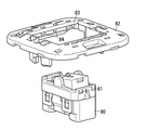
また、従来から、図7及び図8に示すようなスイッチもある。プレート82において挿通穴83の内周面に設けられた係合穴84,84に、スイッチ本体80に設けられた係合凸部81,81を係入させることで、スイッチ本体80をプレート82に着脱自在に結合させていた。
しかしながら、プレート82に対してスイッチ本体80の着脱が繰り返された場合に、スイッチ本体80において係合凸部81の破損が発生しやすかった。そして、係合凸部81が破損した場合にはスイッチ本体80を交換する必要があり、交換のための費用(保守費用)が比較的に高くなっていた。
そこで、本発明の目的は、プレートに対するスイッチ本体の着脱が繰り返された場合における保守費用が抑えられるスイッチを提供することにある。
本発明のスイッチは、壁材に設けられた埋込穴に埋込配設されるスイッチ本体と、前記スイッチ本体が挿通される挿通穴を有してスイッチ本体に着脱自在に結合するとともに前記壁材に対して固定されるプレートとを備え、前記スイッチ本体と前記プレートとの結合は、前記プレートにおいて前記スイッチ本体を挟んで互いに対向する部位に設けられた係合凸部が、スイッチ本体に設けられた係合穴に係入することによって達成されることを特徴とする。
本発明によれば、プレートに対するスイッチ本体の着脱が繰り返された場合に比較的に破損が発生しやすい係合凸部が、スイッチ本体よりも一般に単価が低いプレートに設けられているから、係合凸部がスイッチ本体側に設けられる場合に比べて保守費用が抑えられる。
本発明の好ましい実施形態をさらに詳細に記述する。本発明の他の特徴および利点は、以下の詳細な記述および添付図面に関連して一層良く理解されるものである。
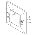
本発明の実施形態に係るスイッチにおけるプレートとスイッチ本体とを示す斜視図である。
本発明の実施形態に係るスイッチを示す分解斜視図である。
本発明の実施形態に係るスイッチを示す前側から見た斜視図である。
本発明の実施形態に係るスイッチを示す後側から見た斜視図である。
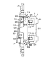
本発明の実施形態に係るスイッチにおいて端子ねじが緩められた状態の要部を示す断面図である。
本発明の実施形態に係るスイッチを示す断面図である。
従来のスイッチにおけるプレートとスイッチ本体とを示す斜視図である。
従来のスイッチにおけるプレートとスイッチ本体とを示す断面図である。
以下、本発明を実施するための最良の形態について、図面を参照しながら説明する。
本実施形態のスイッチを図1~図6に示す。以下、図2に示したABCDEF方向を上下左右前後方向と呼ぶ。本実施形態では、上下方向は、後述する端子ねじ44の軸方向に一致し、上方向(A方向)は、後述する第1端子ねじ451が締めつけられたときの第1端子ナット431の移動方向(第1の方向)であり、下方向(B方向)は、第1の方向とは反対方向であり、後述する第2端子ねじ452が締めつけられたときの第2端子ナット432の移動方向(第2の方向)である。左右方向は、第1の方向と直交し、プレート21の表面と平行な方向であり、左方向(C方向)は、スイッチを正面から見たときの左方向(第3の方向)であり、右方向(D方向)は、第3の方向とは反対方向であり、スイッチを正面から見たときの右方向(第4の方向)である。前後方向は、第1の方向および第3の方向と直交する方向であり、前方向(E方向)とは電線が後述する第1及び第2の電線挿通穴531,532に挿入される方向(第5の方向)であり、後方向(F方向)とは第5の方向とは反対方向であり、後述する操作ハンドル31への押圧方向(第6の方向)である。
このスイッチは、スイッチ本体1と、壁材に設けられた埋込穴(図示せず)にスイッチ本体1を埋込配設する際に用いられるプレート21及び2個の取付金具22とを備える。
スイッチ本体1は、操作ハンドル31を介して操作力を受けて揺動する反転ハンドル32と、可動接点401を有して反転ハンドル32に連動して揺動する接触子40とを備える。また、スイッチ本体1は、接触子40の支点となる支点凸部411を有する第1端子板41と、接触子40の可動接点401が離接する固定接点421が設けられた第2端子板42とを備える。反転ハンドル32は例えば合成樹脂からなり、接触子40と第1及び第2端子板41,42とはそれぞれ例えば金属板からなる。
さらに、スイッチ本体1は、ケーシング51とカバー52とから構成されるハウジング5を備える。ケーシング51は、開口した前面を有し、それにより、接触子40と第1及び第2端子板41,42とがそれぞれ収納される収納凹部50が配設されている。カバー52は、ケーシング51の前側に結合して反転ハンドル32の支点となる。ケーシング51とカバー52とはそれぞれ例えば合成樹脂からなる。
ケーシング51の左右両面において、上下方向(第1及び第2の方向)の中央部には2個の中央凸部511,511が突設され、各中央凸部511の上下両側にはそれぞれ2個の結合凸部512,512が突設されている。
カバー52は、反転ハンドル32を囲む枠状の本体部520と、後方へ突設された4個の結合片521とを有する。4個の結合片521のうちの2個は、本体部520の右端部において上下方向に並べられ、残りの結合片521は、本体部520の左端部において上下方向に並べられている。各結合片521はそれぞれ厚さ方向を左右方向(第3及び第4の方向)に向けた板状であって、1個ずつの結合凸部512が係入する結合穴522が左右に貫設されている。すなわち、ケーシング51の左右両側の各々においてそれぞれ2個の結合片521,521が中央凸部511を挟み、各結合穴522にそれぞれ結合凸部512が係入することで、ケーシング51とカバー52とは互いに結合する。また、結合穴522に対する結合凸部512の係脱時には、結合片521は先端部(後端部)を基部(前端部)に対して左右方向の外側に変位させるように弾性変形する。
また、反転ハンドル32は、全体として直方体形状の本体部320と、本体部320の左右両面から左右方向の外向きにそれぞれ突設された2個の支点凸部321,321とを有する。さらに、カバー52は、本体部520の左右両端部に、前方へ突出する2個の支点受け部523,523を有する。この支点受け部523,523は、それぞれ左右方向の内向きの面に形成された凹部を有する。反転ハンドル32は、各支点凸部321がそれぞれ支点受け部523の前端部に後方から当接することで、上下両端部を中央部に対して前後方向(第5及び第6の方向)に変位させるようにカバー52に対して揺動可能となっている。
また、操作ハンドル31の後面には、反転ハンドル32の前端部が嵌め込まれる嵌合凹部310(図6参照)が設けられている。反転ハンドル32の上下両面には、それぞれ2個の係合凸部322,322が突設されており、各係合凸部322が、嵌合凹部310の内周面において上下両側にそれぞれ設けられた2個の係合凹部312,312にそれぞれ係入することで、操作ハンドル31は反転ハンドル32に一体化されている。
さらに、スイッチ本体1は、コイルばねからなり一端が反転ハンドル32の後端に弾接して他端が接触子40の前面に弾接する反転ばね33を備える。なお、図5では反転ばね33の両端部のみを図示している。反転ばね33のばね力により、反転ハンドル32の各支点凸部321はそれぞれカバー52の支点受け部523に後方から押し付けられ、接触子40は第1端子板41の支点凸部411に前方から押し付けられる。
反転ハンドル32の上端部がハウジング5の前方に突出する状態、つまり、反転ハンドル32が右方から見て反時計回り方向に傾いた状態(以下、「オフ状態」と呼ぶ。)では、反転ばね33は中央部を上下方向において両端部よりも上方に位置させるように曲がる。上記のオフ状態では、反転ばね33のばね力は、反転ハンドル32に対しては反転ハンドル32の上記姿勢を維持させるように作用する。また、接触子40において可動接点401は下向きに設けられ、第2接点板42において固定接点421は上向きに設けられている。従って、上記のオフ状態では、反転ばね33のばね力は、接触子40に対しては可動接点401を固定接点421から離した状態に維持するように作用する。すなわち、オフ状態では、第1端子板41と第2端子板42とは電気的に接続されない。
また、上記のオフ状態において、反転ハンドル32の上端部が操作ハンドル31を介して後向きの押力を受け、反転ハンドル32が反転ばね33のばね力に抗して右方から見て時計回りに回転すると、反転ハンドル32の下端部が中央部よりも前側に変位した時点で、反転ばね33のばね力の向きが反転する。すると、反転ハンドル32は、反転ばね33のばね力により、下端部がハウジング5の前方に突出する状態(以下、「オン状態」と呼ぶ。)に一気に変位する。オン状態では、図5に示すように、反転ばね33は中央部を上下方向において両端部よりも下方に位置させるように曲がり、反転ばね33のばね力は接触子40に対しては可動接点401を固定接点421に押し付けるように作用する。すなわち、オン状態では、第1端子板41と第2端子板42とが接触子40を介して互いに電気的に接続される。操作ハンドル31の、操作力を受ける操作面である前面において、オン状態で後方に押し込まれる上端部には、凸部からなる印311が付されている。なお、印311は凸部に限られず、凹部や印刷や2色成型といった他の方法で付されていてもよい。
さらに、オン状態において、操作ハンドル31を介して反転ハンドル32の下端部が後向きの押力を受け、反転ばね33のばね力に抗して右方から見て反時計回りに回転すると、反転ハンドル32の上端部が中央部よりも前側に変位した時点で、反転ばね33のばね力の向きが反転し、反転ハンドル32はオフ状態に一気に変位する。
また、ケーシング51の収納凹部50内には、第1端子板41に対する1組の端子ナット43及び端子ねじ44(以下、第1端子ナット431及び第1端子ねじ451と称する)と、第2端子板42に対する1組の端子ナット43及び端子ねじ44(以下、第2端子ナット432及び第2端子ねじ452と称する)とが収納される。これらの第1端子ナット431及び第1端子ねじ451と第2端子ナット432及び第2端子ねじ452とを介して、第1及び第2端子板41,42に電線が接続される。第1端子板41は、第1端子ねじ451の頭部441と第1端子ナット431との間に挿入されて第1端子ナット431に対向する第1接触部412を有する。同様に、第2端子板42は、第2端子ねじ452の頭部441と第2端子ナット432との間に挿入されて第2端子ナット432に対向する第2接触部422を有する。第1及び第2接触部412,422は、それぞれ、第1及び第2端子ねじ451,452の軸部442を避ける切り欠き部413,423を有するU字形状である。また、ケーシング51の収納凹部50には、その内周面において、4つの位置決め溝56が設けられている。そのうちの2つは、第1端子板41に対応するように設けられ、互いに対向するように左内面と右内面に形成され、残りの溝56は、第2端子板42に対応するように設けられ、同様に互いに対向するように左内面と右内面に形成されている。第1及び第2端子板41,42は、それぞれ、第1及び第2接触部412,422の左右両端部がそれぞれ上記の対応する位置決め溝56に挿入されることで、ハウジング5に対するがたつきを抑えられている。
また、第1及び第2端子ねじ451,452は、それぞれ収納凹部50内の上下の一方ずつの端部において、軸方向を上下方向に向け、頭部441を上下方向の外側へ向けて収納されている。
さらに、図4に示すように、ケーシング51の収納凹部50の底面には、前後に貫通する貫通穴である一対の第1の電線挿通穴531,531と、一対の第2の電線挿通穴532,532が設けられている。第1の電線挿通穴531,531は、第1端子板41に対応するように収納凹部50の上方に設けられ、第2の電線挿通穴532,532は、第2端子板42に対応するように収納凹部50の下方に設けられている。第1の電線挿通穴531,531は、第1端子板41の第1接触部412よりも僅かに下側に配置される。また、第1の電線挿通穴531,531は、前後方向から見て第1端子ねじ451の軸部442が当該穴531,531の間に位置するように配置されている。同様に、第2の電線挿通穴532,532は、第2端子板42の第2接触部422よりも僅かに上側に配置される。また、第2の電線挿通穴532,532は、前後方向から見て第2端子ねじ452の軸部442が当該穴532,532の間に位置するように配置されている。
また、ケーシング51の上下両端部には、それぞれ第1及び第2端子ねじ451,452の頭部441を露出させる第1及び第2ねじ操作穴541,542が設けられている。従って、第1ねじ操作穴541から挿入したドライバー(図示せず)により第1端子ねじ451を操作することができ、同様に、第2ねじ操作穴542から挿入したドライバーにより第2端子ねじ452を操作することができる。第1及び第2ねじ操作穴541,542の寸法形状は、第1及び第2端子ねじ451,452の頭部441が通過できない程度に十分に小さくされている。
さらに、第1及び第2端子ナット431,432の各々は矩形状であって、収納凹部50の内面に当接することで、ハウジング5に対する回転(連れ回り)を防止されている。
使用者が電線(図示せず)をスイッチ本体1に接続する際には、まず、第1及び第2端子ねじ451,452を十分に緩め、第1端子ナット431を第1の電線挿通穴531よりも下側に、第2端子ナット432を第2の電線挿通穴532よりも上側に位置させる。つまり、第1端子ナット431は、第1端子板41の第1接触部412から離れた側に配置され(第2の方向への移動)、第2端子ナット432は、第2端子板42の第2接触部422から離れた側に配置される(第1の方向への移動)。次に、第1及び第2の電線挿通穴531,532を通じて第1及び第2端子ナット431,432と第1及び第2接触部412,422との間に電線を導入し、第1及び第2端子ねじ451,452を締め付ける。すると、第1端子ねじ451の締め付けに伴って上側(第1の方向)に変位した第1端子ナット431と第1接触部412との間に電線が挟持され(言い換えると、第1端子ナット431により電線が第1接触部412に押し付けられ)、同様に、第2端子ねじ452の締め付けに伴って下側(第2の方向)に変位した第2端子ナット432と第2接触部422との間に電線が挟持され(言い換えると、第2端子ナット432により電線が第2接触部422に押し付けられ)、ここにおいて電線の接続が完了する。ここで、図4に示すように、ハウジング5の後面には、上記の電線の被覆を剥くべき長さと同じ長さを有する基準溝13が設けられており、使用者は、電線を接続する際には基準溝13に電線の先端を置くことで、基準溝13の長さに合わせて電線の被覆を剥くことができる。
また、ハウジング5には、端子ナット43の可動範囲を、端子ナット43が端子ねじ44から分離しないように制限する制限部55が設けられている。具体的には、収納凹部50内には、制限部55として、第1及び第2の制限部551,552が配置され、第1の制限部551は第1端子ナット431の下面の左右の端部に当接してハウジング5に対する第1端子ナット431の可動範囲(下向きへの可動範囲)を制限する。また、第2の制限部552は第2端子ナット432の上面の左右の端部に当接してハウジング5に対する第2端子ナット432の可動範囲(上向きへの可動範囲)を制限する。これにより、制限部55(第1及び第2制限部551,552)は、端子ねじ44(第1及び第2端子ねじ451,452)からの端子ナット43(第1及び第2端子ナット431,432)の脱落を防止する。
また、既に述べたように、上記のスイッチ本体1は、壁材に設けられた埋込穴(図示せず)に対し、プレート21及び2個の取付金具22,22を用いて埋込配設される。
プレート21は、例えば合成樹脂からなり、前方から見た操作ハンドル31の寸法形状よりも僅かに大きい正方形状であってスイッチ本体1が挿通される挿通穴210を有する。また、挿通穴210の上下両側からは、それぞれ厚さ方向を上下方向に向けた2個の結合片216,216が後方へ突設されている。さらに、各結合片216の先端部において、上下方向の内向きの面には、それぞれ4個ずつの係合凸部211が左右方向に並べて上下方向の内向きに突設されている。カバー52の本体部520において上下両面にはそれぞれ2個ずつの係合穴11,11が左右方向に並べて設けられており、各係合穴11にそれぞれ1個ずつの係合凸部211が係入することで、スイッチ本体1はプレート21に対して結合する。また、係合穴11に対する係合凸部211の係脱は、プレート21の結合片216を弾性変形させることで繰り返し行うことができ、これによりスイッチ本体1はプレート21に対して着脱自在となっている。本実施形態では、スイッチ本体1の上下両側の各々における係合穴11、11との係合について、それぞれ、4個の係合凸部211のうち中央の2個の係合凸部211が用いられることで、スイッチ本体1は挿通穴210の中央に取り付けられる。ただし、全ての係合凸部211を用いるとともに、操作ハンドル31を左右方向での寸法が半分のものに変更することで、1個のプレート21に対して2個のスイッチ本体1を左右方向に並べて取り付けることも可能となっている。また、プレート21は、後面側において、後方へ突出する計6つの位置決め凸部215を備える。具体的には、3つの位置決め凸部215が、挿通穴210の上下両側の結合片216の各々に左右に並べて配設されている。さらに、カバー52は、左右に並べて上下方向における外側に突出する計4つの挟み凸部12を備える。具体的には、2つの挟み凸部12がカバー52の上下両面の各々において、それぞれ2つの係合穴11,11の後側に配設されている。すなわち、カバー52の上下両側の各々においてそれぞれプレート21の1個ずつの位置決め凸部215がカバー52の2つの挟み凸部12,12に挟まれることで、プレート21に対するスイッチ本体1の位置決めが達成される。プレート21に取り付けられるスイッチ本体1が1個である場合には、挿通穴210の上下両側の各々において左右に3個並んだ位置決め凸部215のうち中央の位置決め凸部215を用いてスイッチ本体1が位置決めされ、プレート21に取り付けられるスイッチ本体1が2個である場合には、左右に3個並んだ位置決め凸部215のうち左右の2個の位置決め凸部215が用いられる。
各取付金具22は、それぞれ、取付金具22を貫通する取付ねじ23と、取付ねじ23が螺合する取付ナット24とによりプレート21に結合する。具体的には、各取付金具22は、それぞれ例えば金属板からなり、取付ねじ23が挿通されるねじ挿通穴220を有する本体部221と、本体部221の上下両端部からそれぞれ斜め後方に延びながら左右方向の外向きに突設された2つの取付爪222,222とを有する。取付ナット24は矩形状であって、取付金具22の本体部221の後側において2つの取付爪222,222に挟まれることで取付金具22に対する回転を防止される。また、プレート21の前面において、挿通穴210の左右両側には、それぞれ取付ねじ23の頭部が収納される2つのねじ収納凹部212,212が設けられている。さらに、各ねじ収納凹部212の底面には取付ねじ23の軸部が挿通される貫通穴であるねじ挿通穴213が設けられている。各取付金具22は、それぞれ、取付ねじ23によるねじ止め、すなわち、取付ねじ23がプレート21のねじ挿通穴213と取付金具22のねじ挿通穴220とに挿通されて取付ナット24に螺合することで、プレート21に結合している。ここで、プレート21の後面において、計4つの回転止め凸部214が後方へ突設されている。具体的には、挿通穴210の左右両側の各々において、2つの回転止め凸部214,214が取付金具22を上下から挟むように設けられている。取付金具22は、回転止め凸部214に挟まれることで、プレート21に固定される過程でのプレート21に対する回転(いわゆる連れ回り)を防止されている。
プレート21を壁材に固定するには、それぞれ取付爪222の先端が埋込穴を通じて壁材の後側に導入された状態で、取付金具22を、プレート21に固定する。すると、壁材が各取付爪222の先端とプレート21の後面との間に前後方向において挟まれることで、プレート21は壁材に固定される。
ここで、従来のスイッチのスイッチ本体80において、プレート82に対する着脱の際に負荷のかかる部位は、係合凸部81であった。これに対して本実施形態のスイッチのスイッチ本体1において、プレート21に対する着脱の際に負荷のかかる部位は、係合穴11,11の前側の部位(第1壁部11a,11a)である。つまり、第1壁部11aはプレート21の係合凸部211が係合穴11に係合するまでの間、係合凸部211によって押圧され続ける部位である。そして、本実施形態における各第1壁部11aは、後方に突出する形で連続する部位(第2壁部11b)を左右両側に有することで、プレート21の係合凸部211の押圧により受ける力が一対の第2壁部11b,11bを通じて分散される。その結果、従来のスイッチの係合凸部81よりも破損が発生しにくくなっている。
一方で、従来のスイッチのプレート82において、スイッチ本体80が着脱される際に負荷のかかる部位は、係合穴84の後側(図7及び図8での下側)の部位であった。これに対して本実施形態のスイッチのプレート21において、スイッチ本体1が着脱される際に負荷のかかる部位は、係合凸部211である。その結果、プレート21の係合凸部211は比較的に破損しやすくなっている。ただし、一般に、プレート21は、スイッチ本体1に比べれば交換にかかる費用(単価)が低い。
上記構成によれば、プレート21に対するスイッチ本体1の着脱が繰り返された場合に比較的に破損が発生しやすい係合凸部211が、スイッチ本体1よりも一般に単価が低いプレート21に設けられている。従って、単価の高いスイッチ本体側に係合凸部が設けられている従来のスイッチに比べて保守費用が抑えられる。
上述のように、本実施形態に係るスイッチは、壁材に設けられた埋込穴に埋込配設されるスイッチ本体1と、スイッチ本体1が挿通される挿通穴210を有してスイッチ本体1に着脱自在に結合するとともに壁材に対して固定されるプレート21とを備える。スイッチ本体1とプレート21との結合は、プレート21においてスイッチ本体1を挟んで互いに対向する部位に設けられた係合凸部211が、スイッチ本体1に設けられた係合穴11に係入することによって達成される。
本発明を幾つかの好ましい実施形態によって記述したが、この発明の本来の精神および範囲、即ち請求の範囲を逸脱することなく、当業者によって様々な修正および変形が可能である。
Claims (1)
- 壁材に設けられた埋込穴に埋込配設されるスイッチ本体と、
前記スイッチ本体が挿通される挿通穴を有してスイッチ本体に着脱自在に結合するとともに前記壁材に対して固定されるプレートとを備え、
前記スイッチ本体と前記プレートとの結合は、前記プレートにおいて前記スイッチ本体を挟んで互いに対向する部位に設けられた係合凸部が、スイッチ本体に設けられた係合穴に係入することによって達成されることを特徴とするスイッチ。
Priority Applications (1)
| Application Number | Priority Date | Filing Date | Title |
|---|---|---|---|
| EP13837986.2A EP2897145A4 (en) | 2012-09-14 | 2013-08-20 | SWITCH |
Applications Claiming Priority (2)
| Application Number | Priority Date | Filing Date | Title |
|---|---|---|---|
| JP2012-203329 | 2012-09-14 | ||
| JP2012203329A JP6089358B2 (ja) | 2012-09-14 | 2012-09-14 | スイッチ |
Publications (1)
| Publication Number | Publication Date |
|---|---|
| WO2014041748A1 true WO2014041748A1 (ja) | 2014-03-20 |
Family
ID=50277893
Family Applications (1)
| Application Number | Title | Priority Date | Filing Date |
|---|---|---|---|
| PCT/JP2013/004921 Ceased WO2014041748A1 (ja) | 2012-09-14 | 2013-08-20 | スイッチ |
Country Status (3)
| Country | Link |
|---|---|
| EP (1) | EP2897145A4 (ja) |
| JP (1) | JP6089358B2 (ja) |
| WO (1) | WO2014041748A1 (ja) |
Citations (3)
| Publication number | Priority date | Publication date | Assignee | Title |
|---|---|---|---|---|
| JPH04147531A (ja) * | 1990-10-08 | 1992-05-21 | Toshiba Lighting & Technol Corp | 人体検知スイッチの操作装置 |
| JPH10188736A (ja) * | 1996-12-24 | 1998-07-21 | Matsushita Electric Works Ltd | シーソースイッチ |
| JP2001325846A (ja) | 2000-05-15 | 2001-11-22 | Matsushita Electric Works Ltd | スイッチ装置 |
Family Cites Families (5)
| Publication number | Priority date | Publication date | Assignee | Title |
|---|---|---|---|---|
| DE2412949A1 (de) * | 1974-03-18 | 1975-10-09 | Giersiepen Eltech Ind | Elektrotechnisches installationsgeraet, insbesondere schalter oder taster |
| DE9202057U1 (de) * | 1992-02-18 | 1992-04-16 | GIRA Giersiepen GmbH & Co KG, 5608 Radevormwald | Elektrisches Installationsgerät |
| JP4228743B2 (ja) * | 2003-03-26 | 2009-02-25 | パナソニック電工株式会社 | スイッチ |
| ES2249945B1 (es) * | 2003-06-13 | 2006-12-01 | Simon, S.A. | Perfeccionamientos introducidos en los dispositivos electricos de baja tension, destinados indistinta y variablemente a conmutador, pulsador e interruptor. |
| JP4258487B2 (ja) * | 2004-12-20 | 2009-04-30 | パナソニック電工株式会社 | 表示付きスイッチ並びにスイッチ装置 |
-
2012
- 2012-09-14 JP JP2012203329A patent/JP6089358B2/ja not_active Expired - Fee Related
-
2013
- 2013-08-20 EP EP13837986.2A patent/EP2897145A4/en not_active Withdrawn
- 2013-08-20 WO PCT/JP2013/004921 patent/WO2014041748A1/ja not_active Ceased
Patent Citations (3)
| Publication number | Priority date | Publication date | Assignee | Title |
|---|---|---|---|---|
| JPH04147531A (ja) * | 1990-10-08 | 1992-05-21 | Toshiba Lighting & Technol Corp | 人体検知スイッチの操作装置 |
| JPH10188736A (ja) * | 1996-12-24 | 1998-07-21 | Matsushita Electric Works Ltd | シーソースイッチ |
| JP2001325846A (ja) | 2000-05-15 | 2001-11-22 | Matsushita Electric Works Ltd | スイッチ装置 |
Non-Patent Citations (1)
| Title |
|---|
| See also references of EP2897145A4 * |
Also Published As
| Publication number | Publication date |
|---|---|
| JP2014059996A (ja) | 2014-04-03 |
| EP2897145A1 (en) | 2015-07-22 |
| JP6089358B2 (ja) | 2017-03-08 |
| EP2897145A4 (en) | 2015-10-07 |
Similar Documents
| Publication | Publication Date | Title |
|---|---|---|
| JP2013115006A (ja) | 端子台装置 | |
| WO2014125540A1 (ja) | 配線器具 | |
| CN102456490A (zh) | 开关的制造方法及开关 | |
| JP2015060830A (ja) | 電気コネクタ | |
| WO2018173624A1 (ja) | 電力供給用コネクタ装置 | |
| CN1819085B (zh) | 触发开关 | |
| JP5650225B2 (ja) | ウェッジバルブ用ソケット | |
| JP5424364B2 (ja) | 電子機器および投写型表示装置 | |
| JP2011049089A (ja) | ターミナル部材 | |
| WO2014041748A1 (ja) | スイッチ | |
| CN103681019B (zh) | 端子装置 | |
| CN100470977C (zh) | 配线器具 | |
| JP2014059998A (ja) | スイッチ | |
| US20090311922A1 (en) | Low profile contact | |
| JP2008159481A (ja) | 端子装置 | |
| JP2015018605A (ja) | ピアノハンドル式スイッチ | |
| JPH0747807Y2 (ja) | 端子台のアース接続構造 | |
| JP3671618B2 (ja) | コンセント | |
| JP6528299B2 (ja) | 配線器具 | |
| TWI244247B (en) | Wiring instrument | |
| JP4088105B2 (ja) | 直管形蛍光ランプソケット | |
| JPH11185844A (ja) | コンセント | |
| JP5506858B2 (ja) | 回転電機 | |
| JP5042564B2 (ja) | Ledユニット | |
| CN217776901U (zh) | 一种能适配多种供电方式的激光工具 |
Legal Events
| Date | Code | Title | Description |
|---|---|---|---|
| 121 | Ep: the epo has been informed by wipo that ep was designated in this application |
Ref document number: 13837986 Country of ref document: EP Kind code of ref document: A1 |
|
| WWE | Wipo information: entry into national phase |
Ref document number: IDP00201501329 Country of ref document: ID |
|
| NENP | Non-entry into the national phase |
Ref country code: DE |