WO2014041780A1 - シャワー装置 - Google Patents
シャワー装置 Download PDFInfo
- Publication number
- WO2014041780A1 WO2014041780A1 PCT/JP2013/005315 JP2013005315W WO2014041780A1 WO 2014041780 A1 WO2014041780 A1 WO 2014041780A1 JP 2013005315 W JP2013005315 W JP 2013005315W WO 2014041780 A1 WO2014041780 A1 WO 2014041780A1
- Authority
- WO
- WIPO (PCT)
- Prior art keywords
- shower
- arm
- hot
- mixing tap
- type
- Prior art date
- Legal status (The legal status is an assumption and is not a legal conclusion. Google has not performed a legal analysis and makes no representation as to the accuracy of the status listed.)
- Ceased
Links
Images


Classifications
-
- E—FIXED CONSTRUCTIONS
- E03—WATER SUPPLY; SEWERAGE
- E03C—DOMESTIC PLUMBING INSTALLATIONS FOR FRESH WATER OR WASTE WATER; SINKS
- E03C1/00—Domestic plumbing installations for fresh water or waste water; Sinks
- E03C1/02—Plumbing installations for fresh water
- E03C1/04—Water-basin installations specially adapted to wash-basins or baths
- E03C1/0408—Water installations especially for showers
-
- A—HUMAN NECESSITIES
- A47—FURNITURE; DOMESTIC ARTICLES OR APPLIANCES; COFFEE MILLS; SPICE MILLS; SUCTION CLEANERS IN GENERAL
- A47K—SANITARY EQUIPMENT; ACCESSORIES THEREFOR, e.g. TOILET ACCESSORIES
- A47K3/00—Baths; Showers; Appurtenances therefor
- A47K3/28—Showers or bathing douches
- A47K3/281—Accessories for showers or bathing douches, e.g. cleaning devices for walls or floors of showers
- A47K3/282—Seats specially adapted for showers
Definitions
- the present invention relates to a shower device.
- Patent Document 1 Japanese Patent Laid-Open Publication No. 2003-190037 discloses a shower tower equipped with an overhead shower or a hand shower for tapping hot water.
- an overhead shower discharges a shower from a user's head
- the shower head of an overhead shower may be disposed at a position away from the user. Even in such a case, it is difficult for the user to apply the shower discharged from the overhead shower to a desired part.
- the hand shower is a shower head connected to a bendable hose or the like. For this reason, the user can change the position of the shower head of the hand shower, and can apply a shower to a desired part of the body.
- a hand shower needs to have a shower head by hand when used, and may not be easy to use.
- the present invention has been made in view of the above circumstances, and it is an object of the present invention to provide a shower device that can easily apply a shower to a desired part of a user and is easy to use.
- a shower apparatus includes a fixed portion fixed to a bathroom wall, and an arm-type shower provided to be rotatable in the vertical direction with respect to the fixed portion.
- the arm-type shower has a plurality of shower nozzles arranged side by side in the longitudinal direction, and the arm-type shower is configured to be rotatable about a rotation axis parallel to the longitudinal direction.
- the shower apparatus of the 2nd form which concerns on this invention is from the position which the arm type shower discharges a shower toward the user who stood in the bathroom in the 1st form. It is comprised so that it can rotate to the position which rotates below a position and discharges a shower toward the user who sat in the bathroom.
- the shower apparatus of the 3rd form which concerns on this invention is a 1st form.
- WHEREIN The said arm type shower is provided in the right-and-left both sides of the said to-be-fixed part.
- the shower device of the 4th form which concerns on this invention is comprised so that the said both arm type shower can be rotated up and down independently in the 3rd form.
- the shower apparatus of the 5th form which concerns on this invention is connected to the location which the said arm type shower left
- the arm-type shower is configured to be rotatable from the fixed portion to a position protruding rearwardly downward or rearwardly upward.
- a shower apparatus is the shower apparatus according to the first aspect, wherein the fixed portion is constituted by a hot and cold mixing tap, and a hand shower is connected to the hot and cold mixing tap.
- a shower apparatus is the shower apparatus according to the first aspect, wherein the fixed portion is constituted by a hot and cold mixing tap, and an overhead shower is connected to the hot and cold mixing tap.
- a folding chair for sitting at a position where the shower discharged from the arm type shower is taken is provided.
- the shower apparatus of the 9th form which concerns on this invention is the operation part for hot water temperature adjustment in which the said to-be-fixed part is a horizontally long hot-water mixing tap in the 1st form, and the said hot-water mixing tap adjusts hot water temperature.
- the arm-type shower is connected to the longitudinal end of the hot and cold water mixing tap so as to be rotatable in the vertical direction.
- the shower apparatus of the 10th form which concerns on this invention is the operation part for operating the said hot / cold water mixing stopper in the said hot water / water mixing stopper in the said 1st form in which the said to-be-fixed part is a horizontally long hot water / water mixing stopper.
- the operation portion is provided at a position shifted outward from the central portion in the longitudinal direction of the hot and cold water mixing tap.
- the shower apparatus of the 11th form which concerns on this invention is the 2nd shower which discharges a shower toward the user who utilizes the spout part which discharges water below in this 1st form, and this spout part.
- the shower apparatus is further configured to discharge water from the water discharge port and a shower from the second shower nozzle at the same time.
- a shower device is configured in the first aspect such that at least one of the plurality of shower nozzles provided in the arm-type shower can change a discharge direction. Is done.
- a shower device of a thirteenth aspect according to the present invention is the shower apparatus according to the twelfth aspect, comprising: a shower nozzle located closest to the fixed portion side and a shower nozzle located closest to the tip in the longitudinal direction of the arm-type shower.
- at least one of the shower nozzles can change the discharge direction, and the discharge direction of the shower nozzles other than the shower nozzle that can change the discharge direction is fixed in one direction.
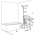
- the shower device 1 can be provided with a chair 3 and an overhead shower 4 as options in addition to the device body 10 having a main function. That is, the chair 3 and the overhead shower 4 are not necessarily required configurations in the shower device 1 of the present embodiment.
- the shower device 1 is provided along the bathroom wall 5 as shown in FIGS. 1 to 3, for example. In addition, below, it demonstrates on the basis of the direction when the shower apparatus 1 is installed in the wall 5.
- FIG. 1 the direction orthogonal to the wall 5 will be referred to as the front-rear direction, and the wall 5 side as viewed from the shower device 1 will be described as the rear side.
- the shower apparatus 1 shown in FIG. 1 includes a chair 3 as an option.
- the shower apparatus 1 shown in FIG. 2 is composed of only the apparatus main body 10.
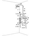
- the shower apparatus 1 shown in FIG. 3 includes an overhead shower 4 as an option.
- the apparatus main body 10 includes a hot and cold water mixing tap 20, an arm type shower 22, a hand shower 23, and a main body cover 24.
- the hot water mixing tap 20 mixes the water supplied from the water supply through the water supply pipe 60 (see FIG. 4) and the hot water supplied from the water heater through the hot water supply pipe 61 (see FIG. 4) to a desired temperature. Produces hot water.
- the water supply pipe 60 and the hot water supply pipe 61 are introduced into the bathroom through a portion corresponding to the main body cover 24 of the wall 5 from the outside of the bathroom, for example, and the portion introduced into the bathroom is connected to the hot and cold mixing plug 20.
- the water supply pipe 60 is provided with a water stop cock 62 for switching the presence or absence of water supply to the hot and cold water mixing plug 20.
- the hot water supply pipe 61 is provided with a water stop cock 63 for switching presence / absence of hot water supply to the hot water / mixing tap 20.
- the stop cocks 62 and 63 are stop cocks with check valves.
- the stop cock 62 is provided in a portion of the water supply pipe 60 that is introduced from the wall 5 into the bathroom.
- the stop cock 63 is provided in a portion of the hot water supply pipe 61 introduced from the wall 5 into the bathroom.
- the hot and cold mixing tap 20 is horizontally long.
- the outer shell of the hot / cold mixing tap 20 is composed of a counter part 200 and a cylindrical part 201 located at the front end of the counter part 200.
- the counter unit 200 is formed in a substantially rectangular box shape that is long on the left and right.
- the rear end of the counter unit 200 is disposed along the vertical wall 5, and the hot and cold mixing plug 20 is attached to the wall 5 in this state. That is, in this embodiment, the hot and cold water mixing tap 20 becomes the fixed portion 2 fixed to the wall 5 in the shower device 1.
- the shower device 1 of the present embodiment includes the fixed portion 2 that is fixed to the bathroom wall 5.
- the fixed portion 2 is constituted by a hot and cold mixing plug 20.
- the hot and cold water mixing tap 20 is installed so that the upper surface of the counter unit 200 is substantially horizontal.
- the upper surface of the counter unit 200 constitutes a mounting unit for mounting small items such as a soap holder and a shampoo bottle.
- the cylindrical portion 201 of the hot / cold mixing tap 20 is located at the front end of the hot / cold mixing tap 20.
- the cylindrical portion 201 is arranged at a position away from the wall 5 when the hot and cold mixing plug 20 is attached to the wall 5.
- Arm type showers 22 are provided at both ends in the longitudinal direction of the hot and cold water mixing tap 20, respectively.
- Each arm-type shower 22 has an arm part 220 and a plurality of shower nozzles 221 (first shower nozzles) provided on the arm part 220.
- each arm type shower 22 is formed in a linear shape, and more specifically in a cylindrical shape.
- One end portion (first end portion 220 ⁇ / b> A) in the longitudinal direction of the arm portion 220 is connected to the hot / cold water mixing plug 20 via a rotating member 222.
- Each rotating member 222 is provided in the cylindrical part 201 of the hot and cold water mixing plug 20 so as to be rotatable in the direction around the left and right axis (first rotation axis).
- the fact that it can rotate about the left-right axis means that it can rotate about a rotation axis parallel to the left-right direction.
- Both arm type showers 22 can be turned up and down independently of the hot and cold water mixing tap 20.
- each arm type shower 22 in the vertical direction is not regulated by the hot and cold water mixing tap 20. For this reason, as shown in FIG. 1 and the like, each arm-type shower 22 projects from the hot and cold water mixing plug 20 rearward and obliquely downward and from the lower position where the tip end abuts against the wall 5 of the bathroom. It is possible to rotate in the range from the rear to the upper position where it protrudes obliquely upward and the tip part abuts against the wall 5 of the bathroom.
- the arm part 220 has a length in one direction.
- the arm unit 220 includes a first end 220A and a second end 220B.
- the first end portion 220A is an end portion on the side of the hot and cold water mixing plug 20 in the length direction.
- the second end 220B is an end opposite to the first end 220A in the length direction.
- a rotation member 222 is provided at the first end 220A.
- the rotation member 222 connects the arm part 220 and the hot and cold mixing plug 20.
- the rotating member 222 connects the arm unit 220 to the hot and cold water mixing plug 20 in a state of being rotatable around the first rotation axis.
- the second end of the arm part 220 is located below the hot water / mixing tap 20 and hits the bathroom wall 5 from a position where it hits the bathroom wall 5 (lower position). Move up to the upper position).
- the arm part 220 provided in the left side of the hot-water / water mixing tap 20 and the arm part 220 provided in the right side are comprised so that it can rotate up and down independently of each other.
- Each rotating member 222 rotates with respect to the hot and cold mixing tap 20 only when a certain force or more is applied. That is, the rotation member 222 allows the arm unit 220 to rotate about the left and right axis when a rotational force is applied to the arm unit 220 about the left and right axis (first rotation axis) with a force greater than a predetermined force. To do. On the other hand, the rotating member 222 regulates the rotation of the arm unit 220 even when a rotational force is applied to the arm unit 220 around the left and right axes with a force less than a certain force. For this reason, each arm type shower 22 is held at a desired rotation position by the hot and cold water mixing tap 20.
- a plurality of shower nozzles 221 are provided in the longitudinal direction of each arm portion 220.
- Each shower nozzle 221 discharges hot water supplied from the hot and cold water mixing tap 20 to the arm type shower 22 as a shower (shower water).
- This shower is composed of a large number of water streams that are diffused and discharged at a wide angle.
- the water flow which comprises this shower is a fine water flow about 400 micrometers in diameter.
- the shower nozzles 221 of each arm type shower 22 are arranged in a line in the longitudinal direction of the arm part 220 at equal intervals. Each shower nozzle 221 is disposed at the same position in the circumferential direction of the arm portion 220. The directions of the shower nozzles 221 provided on the same arm portion 220 are all the same. For this reason, showers are discharged in substantially the same direction from the shower nozzles 221 provided on the same arm portion 220. Both arm parts 220 are symmetrical. For this reason, the shower nozzles 221 of both arm parts 220 can be arranged at positions facing each other.
- the discharge directions of the plurality of shower nozzles 221 provided in one arm portion 220 are all directed in the same direction, but the following configuration is also possible. Good.
- Each arm part 220 is provided with a plurality of nozzle attachment parts 27 (see FIG. 6) for attaching the shower nozzle 221.
- nozzle attachment parts 27 see FIG. 6 for attaching the shower nozzle 221.
- a plurality of shower nozzles 221 are provided in the arm portion 220 at a constant interval.
- the shower nozzles 221 are located on the same straight line.
- the direction in which the shower nozzles 221 are arranged is parallel to the longitudinal direction of the arm portion 220.
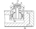
- the shower nozzle 221 located closest to the fixed portion 2 side (first end portion 220A side) and the shower nozzle located closest to the tip end side (second end portion 220B side) 221 is constituted by the discharge direction free nozzle 25. Further, the nozzles other than the discharge direction free nozzle 25 are constituted by a discharge direction fixed nozzle 26.
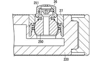
- FIG. 6B An example of the discharge direction free nozzle 25 is shown in FIG. 6B.
- the discharge direction free nozzle 25 is configured to change the discharge direction of the shower. More specifically, the discharge direction of the discharge direction universal nozzle 25 can be changed within a predetermined range between the longitudinal direction of the arm portion 220 and the direction perpendicular to the longitudinal direction, and as a result, the arrow A in FIG. When viewed in the direction, it can be changed within a range of 360 °.
- the discharge direction free nozzle 25 includes a nozzle body 250 and an ejection part 251.
- the nozzle body 250 includes a movable portion 252 that is rotatably held by the nozzle mounting portion 27, and a protruding portion 253 that protrudes from the movable portion 252.
- the ejection part 251 is attached to the projecting tip of the projecting part 253. Since the discharge direction universal nozzle 25 is provided with the protruding portion 253, the discharge direction can be changed within a range that does not interfere with the arm portion 220.
- the discharge direction fixed nozzle 26 is one in which the discharge direction of the shower is fixed in one direction.
- the discharge direction fixed nozzle 26 includes a nozzle body 250 and an ejection part 251.
- a jet part 251 is attached to the nozzle body 250.
- a nozzle mounting portion 27 is close to the ejection portion 251.
- the discharge direction fixed nozzle 26 is configured such that the discharge direction cannot be changed due to the ejection portion 251 interfering with the nozzle mounting portion 27, and the discharge direction is fixed in a constant direction.
- the discharge direction universal nozzle 25 is used for only one of the shower nozzle 221 located closest to the fixed portion 2 and the shower nozzle 221 located on the opposite side among the plurality of shower nozzles 221. It may be done. Further, not only the shower nozzle 221 at the end of the shower nozzle 221 aligned in the longitudinal direction of the arm unit 220, but only one of them may be configured by the discharge direction universal nozzle 25.
- each arm type shower 22 rotates about a rotation axis (second rotation axis) parallel to the longitudinal direction of the arm portion 220 (direction orthogonal to the left-right direction) with respect to the rotation member 222. It is provided as possible. By rotating each arm part 220 with respect to the rotation member 222, the direction of the plurality of shower nozzles 221 provided in each arm part 220 can be changed to a desired direction. Each arm portion 220 can be rotated by one rotation (360 °) or more around the second rotation axis with respect to the rotation member 222.
- each shower nozzle 221 can be rotated from a state in which the direction of each shower nozzle 221 is directed toward the other arm unit 220 to a state in which the shower nozzle 221 is directed to the outer side opposite to the other arm unit 220.
- the arm portion 220 of each arm type shower 22 rotates with respect to the rotation member 222 only when a certain force or more is applied around the second rotation axis. For this reason, each arm part 220 is held at a desired rotation position around the second rotation axis by the rotation member 222.
- the main body cover 24 of the apparatus main body 10 is formed in a groove shape whose horizontal cross-sectional shape opens rearward.
- the main body cover 24 is detachably attached to the hot / cold mixing tap 20 and / or the wall 5.
- the main body cover 24 is disposed adjacent to the lower side of the hot and cold water mixing tap 20. Portions of the water supply pipe 60 and the hot water supply pipe 61 drawn into the bathroom from the wall 5 and the stop cocks 62 and 63 provided in the same portion are covered with the main body cover 24.
- the water stop cocks 62 and 63 can be operated by removing the main body cover 24.
- the main body cover 24 has a width in the left-right direction.
- a water discharge port 240 is provided at the center in the width direction of the lower surface of the main body cover 24.
- the water discharge port 240 is open downward.
- the water outlet 240 is connected to the hot and cold water mixing plug 20 through a pipe (not shown) covered with the main body cover 24.
- the hot water supplied from the hot water mixer tap 20 to the water discharge port 240 is discharged downward as a single water flow. This water flow is considerably thicker than the water flow discharged from the overhead shower 4 or the hand shower 23.
- a base portion 241 projecting downward is formed on both sides of the lower surface portion of the main body cover 24 in the width direction.
- Each pedestal portion 241 has a front portion that faces obliquely downward.
- a shower nozzle 242 (second shower nozzle 28) is provided on the front surface of each table 241. Both shower nozzles 242 are arranged at the same level. Further, both shower nozzles 242 and the water discharge port 240 are located at the same level. Both shower nozzles 242 are arranged below the hot and cold water mixing tap 20. Further, both shower nozzles 242 and water discharge port 240 are disposed between both arm type showers 22 in the left-right direction.
- Each shower nozzle 242 is connected to the hot and cold water mixing tap 20 through a pipe (not shown) covered with the main body cover 24.
- Each shower nozzle 242 is provided so as to protrude from the base 241 toward the front side, and a nozzle hole for discharging the shower is formed at the tip of the shower nozzle 242.
- Each shower nozzle 242 discharges the hot water supplied from the hot water mixing tap 20 as a shower.
- This shower is composed of a large number of water streams that are diffused and discharged at a wide angle, similar to those discharged from the shower nozzle 221 of the arm type shower 22.
- the water flow which comprises this shower is a fine water flow about 400 micrometers in diameter.
- Each shower nozzle 242 is provided to be rotatable with respect to the base 241 of the main body cover 24 via a universal joint 243. For this reason, the direction of each shower nozzle 242 can be changed to either the up-down direction or the left-right direction.
- the height at which the apparatus main body 10 of the shower apparatus 1 is provided is appropriately determined according to the usage pattern. For example, when the chair 3 is provided as shown in FIG. 1, the apparatus main body 10 is provided at a high position. When the chair 3 is not provided, the apparatus main body 10 can be provided at a low position as shown in FIG. 2 or at a high position as shown in FIG.
- the shower nozzle 242 is a leg of a user standing immediately in front of the shower apparatus 1 or a leg of a user sitting using a bath chair or the like. It is arranged at a position close to the part. In this case, the shower nozzle 242 mainly discharges the shower toward the legs of the user. Moreover, when the apparatus main body 10 is provided at a high position as shown in FIG. 3, the shower nozzle 242 is disposed at a position close to the waist of the user standing in front of the shower apparatus 1. In this case, the shower nozzle 242 mainly discharges the shower toward the user's waist.
- the hand shower 23 includes a connecting pipe 231 that can be bent, and a shower head 232 provided at one end of the connecting pipe 231.
- the connecting tube 231 is configured by a bendable bellows tube, a flexible hose, or the like.
- the end of the connecting pipe 231 opposite to the shower head 232 is connected to one end in the longitudinal direction of the hot and cold water mixing tap 20.
- the hand shower 23 is detachably attached to a hook 65 provided on the wall 5. That is, the hand shower 23 is connected to the hot / cold mixing tap 20.
- the shower head 232 is detachably held by the hook 65.
- the overhead shower 4 is attached to the shower device 1 as an option. As shown in FIG. 3, the overhead shower 4 includes a rising pipe 40 and a shower head 41.
- the riser pipe 40 is connected to the counter unit 200 of the hot and cold water mixing tap 20.
- the riser tube 40 is raised from the central portion in the left-right direction of the counter unit 200, then bent toward the front side opposite to the wall 5, and thereafter bent toward the lower side.
- a plurality of vertical portions of the rising pipe 40 that are raised from the counter unit 200 are fixed to the wall 5.
- the shower head 41 is provided at the tip of the riser tube 40.
- the shower head 41 is disposed at a higher position than the hot and cold water mixing tap 20.
- the shower head 41 is disposed above the tip of the arm type shower 22 positioned at the uppermost position.
- the overhead shower 4 includes the riser 40 and the shower head 41.
- the riser pipe 40 is connected to the hot and cold water mixing tap 20.
- the riser tube 40 includes a long tube portion 40A, a horizontal tube portion 40B, and a short tube portion 40C.
- the long tube portion 40A, the horizontal tube portion 40B, and the short tube portion 40C communicate with each other.
- the long pipe portion 40A protrudes upward from the counter portion 200.
- the horizontal tube portion 40B protrudes forward from the upper end of the long tube portion 40A.
- the short tube portion 40C protrudes downward from the front end of the horizontal tube portion 40B.
- a shower head 41 is provided at the lower end of the short tube portion 40C.
- the chair 3 is foldable (that is, the shower device 1 is provided with a foldable chair).
- the chair 3 includes a chair body 30 and a backrest 31 as shown in FIG.
- the backrest 31 includes a cover 310 and a shower nozzle 311 provided on the cover 310.
- the cover 310 is formed in a groove shape whose horizontal cross-sectional shape opens rearward.
- the cover 310 has a width in the left-right direction.
- the dimension of the cover 310 in the width direction is the same as the dimension of the main body cover 24 in the width direction.
- the cover 310 is attached to the wall 5 and / or the body cover 24.
- the cover 310 is disposed adjacent to and below the main body cover 24.
- the cover 310 has an appearance that is continuous with the main body cover 24.
- the cover 310 covers the water discharge port 240 and the shower nozzle 242 of the main body cover 24. That is, when the chair 3 is provided as an option, the water outlet 240 and the shower nozzle 242 are not used. In this case, the water outlet 240 and the shower nozzle 242 are not connected to the hot water mixing tap 20. In addition, when using the chair 3, you may use the main body cover 24 in which the spout part 240 and the shower nozzle 242 are not provided.
- a bend portion 312 bulging slightly forward is formed on the front surface of the cover 310.
- a concave portion 313 that is recessed rearward is formed on the upper portion of the bent portion 312.
- Shower nozzles 311 are respectively provided on the left and right sides of the inner surface of the recess 313. Both shower nozzles 311 are located at the same level. Both shower nozzles 311 are connected to the hot and cold water mixing plug 20 via a pipe (not shown) covered by the main body cover 24 and the backrest 31.
- Each shower nozzle 311 discharges hot water supplied from the hot-water mixing tap 20 as a shower.
- This shower is composed of a large number of water streams that are diffused and discharged at a wide angle, similar to those discharged from the shower nozzle 221 of the arm type shower 22.
- the water flow which comprises this shower is a fine water flow about 400 micrometers in diameter.
- Each shower nozzle 311 is provided so as to protrude from the bottom of the recess 313 toward the front side, and a nozzle hole 315 for discharging a shower is formed at the tip of the shower nozzle 311.
- Each shower nozzle 311 is provided so as to be rotatable with respect to the drooping portion 312 via a universal joint portion 314. Thereby, each shower nozzle 311 can change the direction (discharge direction) to both the up-down direction and the left-right direction.
- the discharge direction of the shower nozzle 311 is a direction parallel to the center line of the shower.
- the chair body 30 includes a seat portion 300 and front and rear leg portions 301 and 302.
- the rear leg 301 is attached to the wall 5 or the backrest 31 or both.
- the leg part 301 has a width in the left-right direction.
- the widthwise dimension of the leg 301 is the same as the widthwise dimension of the cover 310 of the backrest 31.
- the leg portion 301 is arranged adjacent to the lower side of the backrest 31.
- the leg 301 has an appearance that is continuous with the cover 310 of the backrest 31.
- the leg 301 is disposed between the backrest 31 and the bathroom floor.
- the leg 301 is also placed on the bathroom floor.
- the seat part 300 is formed in a substantially plate shape. As shown in FIG. 5B, the seat portion 300 is connected to the upper end portion of the leg portion 301 so as to be rotatable about the left-right axis when positioned substantially horizontally. Thus, the seat 300 is changed from a substantially horizontal state (use position) as shown in FIG. 5B to a substantially vertical state (non-use position) along the front surface of the backrest 31 as shown in FIG. 5A. It is possible to rotate in the vertical direction within the range.
- the front leg portion 302 is formed in a substantially plate shape.
- the leg 302 is substantially vertical, the end located at the upper end is connected to the end of the seat 300 opposite to the side where the leg 301 is connected so as to be rotatable about the left-right axis. Accordingly, the leg 302 is substantially parallel to the seat 300 as shown in FIG. 5A from the state (usage position) that is substantially perpendicular to the seat 300 as shown in FIG. 5B. It can be rotated in the range up to (non-use position).
- each shower nozzle 311 is set on the back side of the user.
- each arm type shower 22 is provided at a position where the user who is sitting on the chair 3 as described above can apply the shower discharged from the shower nozzle 221.
- the seat portion 300 and the front leg portion 302 are disposed in the non-use position, the seat portion 300 and the front leg portion 302 are disposed along the front surface of the bend portion 312 and the chair body. 30 will be in the folded state.
- the arm-type shower 22, the water discharge port 240, the shower nozzle 242, the hand shower 23, the overhead shower 4, and the shower nozzle 311 constitute a hot water discharge unit of the shower device 1.
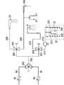
- a cylinder (not shown) is built in the cylindrical portion 201 (see FIG. 1 and the like) of the hot and cold mixing tap 20.
- the cylinder incorporates a thermo valve 202, a first switching valve 203, and a second switching valve 204 shown in FIG. 4 as valve devices.
- a water supply pipe 60 and a hot water supply pipe 61 are connected to the thermo valve 202 in communication.
- a flow path 205 on the downstream side of the thermo valve 202 formed in the cylinder branches into two flow paths 206 and 207.
- One of the flow paths 206 is further branched into a first water supply path 208 and a second water supply path 209.
- the other channel 207 further branches into a third water supply channel 210 and a fourth water supply channel 211.
- the hand shower 23 is directly connected to the first water supply channel 208.
- a water discharge port 240 is connected to the second water supply passage 209 via a pipe (not shown) covered with the main body cover 24.
- a shower nozzle 311 is connected to the second water supply channel 209 via a pipe covered with the main body cover 24 and the backrest 31 instead of the water discharge port 240.
- the overhead shower 4 is provided as an option, the overhead shower 4 is directly connected to the third water supply channel 210.
- the arm type shower 22 is directly connected to the fourth water supply channel 211.
- the shower nozzle 242 is used, the shower nozzle 242 is connected to the fourth water supply channel 211 through a pipe covered with the main body cover 24.
- a high cut valve 213 is provided on the upstream side of the arm type shower 22 and the shower nozzle 242 in the fourth water supply path 211.
- the 1st switching valve 203 is provided in the location which branches into the 1st water supply path 208 and the 2nd water supply path 209 in the flow path 206.
- FIG. A second switching valve 204 is provided at a location where the flow path 207 branches into the third water supply path 210 and the fourth water supply path 211.
- the cylindrical portion 201 that is long on the left and right sides of the hot and cold water mixing tap 20 is provided with a plurality of handles 214 to 216 as operation portions.
- the operation unit 21 is for operating the hot and cold water mixing tap 20.
- the operation unit 21 includes handles 214, 215, and 216.
- the handles 214 to 216 are positioned on the inner side of both ends to which the arm type shower 22 is connected in the longitudinal direction (left and right direction) of the cylindrical portion 201. Further, the handles 214 to 216 are provided at positions shifted outward from the central portion in the longitudinal direction of the hot and cold mixing tap 20. That is, all the operation parts 21 are not provided in the center part in the longitudinal direction of the hot-water mixing tap 20.
- Each handle 214 to 216 has a cylindrical portion 217 and a protruding portion 218.
- the outer peripheral surface of the cylindrical portion 217 of each handle 214 to 216 is substantially flush with the outer peripheral surface of the cylindrical portion 201.
- the protrusions 218 of the handles 214 to 216 protrude from a part in the circumferential direction of the cylindrical portion 217 toward the radially outward direction.
- the cylindrical portion 217 is provided so as to be rotatable around the left-right axis with respect to the cylindrical portion 201 of the hot and cold mixing tap 20.
- Each of the handles 214 to 216 can be turned up and down with respect to the cylindrical portion 217 by operating the projection 218 with fingers.
- the handle 214 is provided on the left side of the hot-water mixing tap 20. By rotating the handle 214 up and down, the ratio of hot water and water mixed by the thermo valve 202 changes. That is, the handle 214 constitutes a hot water temperature adjusting operation unit 29 for adjusting the hot water temperature.
- the handle 215 is provided on the right side of the hot-water mixing tap 20.
- the first switching valve 203 is switched to one of the first water supply path 208 side, the second water supply path 209 side, and the water stop state.
- the hot water mixed by the hot water mixing tap 20 is supplied to the hand shower 23.
- the hot water mixed by the hot water mixing tap 20 is supplied to the water discharge port 240 or the shower nozzle 311.
- the first switching valve 203 is switched to the water stop state, the supply of hot water to the first water supply path 208 and the second water supply path 209 is stopped.
- the handle 216 is provided on the right side of the hot-water mixing tap 20.
- the handle 216 is disposed adjacent to the right side of the handle 215.
- the second switching valve 204 is switched to one of the third water supply channel 210 side, the fourth water supply channel 211 side, and the water stop state.
- the hot water mixed in the hot water mixing tap 20 is supplied to the overhead shower 4.
- the second switching valve 204 is switched to the fourth water supply channel 211 side
- hot water mixed by the hot water mixing tap 20 is supplied to the arm type shower 22 and the shower nozzle 242.
- the second switching valve 204 is switched to the water stop state, the supply of hot water to the third water supply path 210 and the fourth water supply path 211 is stopped.
- the arm-type shower 22, the water discharge port 240, the shower nozzle 242, the hand shower 23, the shower nozzle 311 and the overhead shower 4 of the shower device 1 are used as follows, for example. This use is performed after opening the stop cocks 62 and 63 and adjusting the temperature of the discharged hot water by operating the handle 214.
- the user can use the arm-type shower 22 by operating the handle 216 of the hot-water mixing tap 20 to switch the second switching valve 204 to the fourth water supply channel 211 side. If it does in this way, the hot water mixed with the hot-water mixing tap 20 will be supplied to each arm type shower 22 via the 4th water supply path 211, and will be discharged from each shower nozzle 221. Thereby, the user can be located between both arm type showers 22 and can take hot water (shower) discharged from each shower nozzle 221.
- each arm type shower 22 up and down with respect to the hot and cold water mixing tap 20 so that the arm type can be used regardless of whether it is standing or sitting.
- the shower discharged from the shower 22 can be taken on a desired part of the body.
- the user when the user wants to take a shower while standing in front of the shower device 1, the user turns the arm-type shower 22 upward from the horizontal as shown in FIG.
- the shower nozzle 221 may be directed to the front side.
- the user can take the shower discharged from the arm-type shower 22 from the head side while standing in the bathroom, or take the shower on the upper body.
- the user when the user wants to take a shower while sitting in front of the shower device 1 using the chair 3 or a bath chair, the user lowers the arm type shower 22 below the position shown in FIG. 5A. It is only necessary to turn to. As a result, the user makes the arm-type shower 22 substantially horizontal as shown in FIG.
- the arm-type shower 22 or arranges the arm-type shower 22 at a rotational position below the horizontal (inclined so as to be positioned downward toward the tip). State). Therefore, the user can take a shower discharged from the arm-type shower 22 while sitting on the chair 3 or a bath chair.
- both arm type showers 22 can be independently turned up and down. For this reason, for example, the user rotates one arm-type shower 22 above the horizontal and the other arm-type shower 22 below the horizontal, and is discharged from both arm-type showers 22. You can also take a shower over a wide area of the body.
- the user rotates the arm portion 220 of each arm type shower 22 with respect to the rotation member 222 so that the orientation of the plurality of shower nozzles 221 provided on the arm portion 220 is changed to a desired portion of the user. It can also be changed to hit.
- the shower device 1 does not include the chair 3 as an option
- the hot water mixed by the hot water mixing tap 20 is also supplied to each shower nozzle 242.
- the This hot water is discharged from each shower nozzle 242 to the front side.
- a user standing in the bathroom or sitting in the bathroom using a bath chair or the like takes a shower discharged from the arm-type shower 22 and at the same time from each shower nozzle 242 located on the wall 5 side.
- the discharged shower can be taken on the back, waist, legs, etc.
- the user can adjust the vertical and horizontal directions of each shower nozzle 242. For this reason, the user can take a shower discharged from each shower nozzle 242 at a desired site.
- each arm type shower 22 When each arm type shower 22 is not used, the user turns each arm type shower 22 to the wall 5 side with respect to the hot and cold water mixing tap 20 so that each arm type shower 22 is shown in FIG. As described above, it can be arranged at a position protruding rearward and obliquely downward from the hot-water mixing tap 20. In this case, the user may be disposed at a position protruding obliquely upward from the hot and cold water mixing tap 20.
- each arm-type shower 22 can be disposed at a position where it is difficult for a person in the bathroom to get in the way.
- a gap 64 for inserting a hand can be formed between the wall 5 and the arm type shower 22. .
- the user when the user holds the arm-type shower 22 projecting from the hot and cold water mixing tap 20 obliquely downward or rearward and upward and pulls it forward, the user can easily put the arm-type shower 22 through the gap 64. I can grab it.
- the user can use the water discharge port 240 by operating the handle 215 of the hot-water mixing tap 20 to switch the first switching valve 203 to the second water supply channel 209 side. If it does in this way, the hot water mixed with the hot water mixing tap 20 will be discharged from the spout part 240. FIG. Further, when the user is discharging hot water from the water discharge port 240 in this way, the user can switch the second switching valve 204 to the fourth water supply channel 211 side to discharge the shower from each arm type shower 22. it can. At this time, showers can also be discharged from each shower nozzle 242 (second shower nozzle 28).
- the user can use the hand shower 23 by operating the handle 215 of the hot-water mixing tap 20 to switch the first switching valve 203 to the first water supply path 208 side. If it does in this way, the hot water mixed with the hot-water mixing tap 20 will be discharged from the shower head 232 of the hand shower 23 as a shower. Thereby, the user can take a shower discharged from the hand shower 23 at a desired site. Further, when hot water is being discharged from the hand shower 23 in this way, the user can also discharge the shower from each arm type shower 22 by switching the second switching valve 204 to the fourth water supply channel 211 side. it can. At this time, if the shower device 1 does not include the chair 3, the shower can be discharged from each shower nozzle 242.
- the shower device 1 includes the chair 3 as an option
- the user can use each shower nozzle 311 provided on the backrest 31.
- the chair body 30 is pulled out forward as shown in FIGS. 1 and 5B, and in this state, the handle 215 of the hot-water mixing tap 20 is operated to perform the first operation.
- the switching valve 203 may be switched to the second water supply channel 209 side. If it does in this way, the hot water mixed with the hot water mixing tap 20 will be discharged from each shower nozzle 311 of the backrest 31. FIG.
- each of the shower nozzles 311 can be adjusted in the vertical and horizontal directions. For this reason, the user sitting on the chair 3 can take a shower discharged from each shower nozzle 242 at a desired site such as the back or waist.
- each shower nozzle 311 When hot water is discharged from each shower nozzle 311 in this way, the user can cause the shower to be discharged from each arm type shower 22 by switching the second switching valve 204 to the fourth water supply channel 211 side. Can do. For this reason, the user takes a shower discharged from the arm-type shower 22 while sitting on the chair 3, and at the same time, uses the shower discharged from each shower nozzle 311 arranged on the back side of the user. And so on.
- the user can use the overhead shower 4 by operating the handle 216 of the hot and cold mixing tap 20 to switch the second switching valve 204 to the third water supply channel 210 side. . If it does in this way, the hot water mixed with the hot-water mixing tap 20 will be discharged from the shower head 41 of the overhead shower 4 as a shower. For this reason, the user can take the shower discharged from the overhead shower 4 from the head side (upper side).
- the shower device 1 of the present embodiment has the following first feature.
- the shower device 1 includes a fixed portion 2 fixed to the wall 5 of the bathroom, and an arm-type shower 22 provided so as to be rotatable in the vertical direction with respect to the fixed portion 2. .
- the arm shower 22 is provided with a plurality of shower nozzles 221 arranged in the longitudinal direction of the arm shower 22.
- the arm-type shower 22 is configured to be rotatable about a rotation axis (second rotation axis) parallel to the longitudinal direction.
- the shower device 1 of the present embodiment allows the user to rotate the arm-type shower 22 up and down with respect to the hot and cold mixing tap 20 so that the shower discharged from the arm-type shower 22 is a desired part of the body.
- the arm-type shower 22 has a plurality of shower nozzles 221 arranged in the longitudinal direction thereof, and the arm-type shower 22 is rotatable about a rotation axis parallel to the longitudinal direction.
- the user can also rotate the arm-type shower 22 with respect to the rotation member 222, and can take the shower discharged from the shower nozzle 221 in a user's desired site
- the direction of the plurality of shower nozzles 221 can be changed by a single operation of rotating the arm-type shower 22 with respect to the rotation member 222, which is easy to use.
- the shower device 1 of the present embodiment may have the following second to thirteenth features.
- the second to thirteenth features are arbitrary features.
- the arm-type shower 22 is rotated from the position above the horizontal and discharges the shower toward the user standing in the bathroom.
- it is configured to be able to rotate to a position where the shower is discharged toward the user sitting in the bathroom by rotating downward (below the horizontal).
- the posture of the arm-type shower 22 that discharges the shower toward the user sitting in the bathroom may be inclined downward from the horizontal, or inclined upward from the horizontal. Alternatively, it may be in a horizontal state.
- the user appropriately turns the arm shower 22 up and down so that the shower discharged from the arm shower 22 can stand in the bathroom. You can take it when you are in a sitting or sitting state.
- the arm type showers 22 are provided on both the left and right sides of the fixed portion 2 in the first feature.
- the user can take a shower discharged from the arm-type shower 22 located on both the left and right sides.
- both arm-type showers 22 can be independently rotated in the vertical direction.
- the user can rotate the arm-type showers 22 on the left and right sides independently of each other, which is convenient.
- the arm-type shower 22 is connected to the portion to be fixed in the fixed portion 2 so as to be able to rotate in the vertical direction at a position away from the bathroom wall 5.
- the arm-type shower 22 is configured to be able to rotate from the fixed portion 2 to a position protruding rearwardly downward or obliquely upward.
- each arm type shower 22 protrude toward the back diagonally downward or back diagonally upward from the hot-water mixing tap 20, and is bathroom. It can be placed at a position where it is difficult for people in the area to get in the way.
- each arm-type shower 22 is projected rearwardly downward or obliquely upwardly in this manner, a gap 64 for inserting a hand can be formed between the wall 5 and the arm-type shower 22. .
- the user holds the arm-type shower 22 protruding from the hot / cold mixing tap 20 obliquely downward rearward or rearwardly upward as described above, the user inserts his hand from the gap 64 and enters the arm type The shower 22 can be easily grasped.
- the user can keep the tip of the arm-type shower 22 projecting from the hot and cold mixing tap 20 obliquely downward or rearward upward in contact with the wall 5. Therefore, the arm type shower 22 can be fixed by supporting the tip of the arm type shower 22 with the wall 5.
- the fixed portion 2 is constituted by the hot and cold water mixing tap 20.
- a hand shower 23 is connected to the hot-water mixing tap 20.
- the user can take a shower at a desired part of the body using the hand shower 23.
- the hot-water mixing tap 20, the arm type shower 22, and the hand shower 23 can be unitized, and the installation of the shower apparatus 1 can be made easy.
- the fixed portion 2 is constituted by the hot and cold water mixing tap 20.
- An overhead shower 4 is connected to the hot-water mixing tap 20.
- the user can take a shower from overhead using the overhead shower 4.
- the hot-water mixing tap 20, the arm type shower 22, and the overhead shower 4 can be unitized, and construction of the shower apparatus 1 can be made easy.
- the folding chair 3 is provided in the first feature.
- the folding chair 3 is for a user to sit at a position where a user takes a shower discharged from the arm-type shower 22.
- the user can take a shower discharged from each arm-type shower 22 while sitting on the chair 3.
- the chair 3 can be placed at a position that is unlikely to be an obstacle for a person in the bathroom.
- a space for standing immediately in front of the shower device 1 can be secured.
- the fixed portion 2 is constituted by a horizontally long hot and cold water mixing tap 20.
- the hot and cold water mixing plug 20 has a hot water temperature adjusting operation unit 29 for adjusting the hot water temperature.
- the arm-type shower 22 is connected to the longitudinal end of the hot and cold water mixing tap 20 so as to be able to rotate in the vertical direction.
- the arm-type shower 22 is connected to the horizontally long hot-water mixing tap 20, the hot-water mixing tap 20 and the arm-type shower 22 are unitized. can do. Therefore, when the shower device 1 is installed, the trouble of connecting the arm-type shower 22 to the hot and cold mixing tap 20 via a pipe or the like can be saved, and the shower device 1 can be easily installed. Further, the arm type shower 22 can be disposed at a position close to the operation part 29 for adjusting the hot water temperature provided in the hot water / water mixing tap 20. For this reason, a user who uses the arm-type shower 22 can easily operate the handle 214.
- the fixed portion 2 is composed of a horizontally long hot and cold water mixing tap 20.
- the hot / cold mixing tap 20 is provided with an operation unit 21 for operating the hot / cold mixing tap 20.
- the operation unit 21 is provided at a position shifted outward from the central portion in the longitudinal direction of the hot and cold mixing plug 20.
- the operation unit 21 (handles 214 to 216) is hard to hit the user. Thereby, the usability of the shower apparatus 1 can be improved.
- the shower apparatus 1 includes a water outlet portion 240 that discharges water downward, and a second outlet that discharges a shower toward a user who uses the water outlet portion 240.
- a shower nozzle 28 is further provided.
- the shower device 1 is configured such that water from the water discharge port 240 and the shower from the second shower nozzle 28 can be discharged simultaneously.
- the user can comfortably use the water discharge port 240 while taking a shower discharged from the second shower nozzle 28. .
- At least one shower nozzle 221 is configured to change the discharge direction.
- the user discharges from the shower nozzle 221 by adjusting the angle of the arm type shower 22 and the discharge direction of the shower nozzle 221 respectively.
- the shower to be performed can be applied to a desired part of the user's body.
- the thirteenth feature is configured as follows in the twelfth feature.
- the shower nozzles 221 located closest to the fixed portion 2 side and the shower nozzle 221 located closest to the distal end side in the longitudinal direction of the arm type shower 22 at least one shower nozzle 221 can change the discharge direction. Composed. Of all the shower nozzles 221 provided in the arm-type shower 22, the shower nozzles 221 other than the shower nozzle 221 that can change the discharge direction are fixed in one direction (the discharge direction cannot be changed). Configured). When two shower nozzles 221 that can change the discharge direction are provided, three or more shower nozzles 221 including the shower nozzle 221 that can change the discharge direction are provided.
- the arm type shower 22 is moved around the second rotation axis. Control of the discharge direction of the plurality of shower nozzles 221 can be easily performed only by rotating. Furthermore, since the discharge direction of the shower nozzle 221 at least one of the shower nozzles 221 arranged in a line is variable, even when the arm-type shower 22 is inclined, all of the shower nozzles 221 are arranged. It is easy to apply the shower to the user's body.
- the shower device 1 has the above-described configuration, so that the arm type shower 22 can be discharged from the arm type shower 22 only by rotating the arm type shower 22 up and down with respect to the hot and cold mixing tap 20.
- the shower can be easily applied to the desired part of the body.
- the shower device 1 of the present embodiment has the above-described configuration, so that the user rotates the arm-type shower 22 around a rotation axis (second rotation axis) parallel to the longitudinal direction thereof.
- the shower discharged from the shower nozzle 221 can be applied to a desired part of the user.
- the user changes the orientation of the plurality of shower nozzles 221 simply by rotating the arm-type shower 22 around the rotation axis (second rotation axis). be able to.
- the user can easily apply the shower to a desired part of the body.
- the arm type shower 22 is connected to the hot and cold water mixing tap 20, but the arm type shower 22 may be connected to the fixed portion 2 other than the hot water and water mixing tap 20 fixed to the wall 5. Further, in the present embodiment, the arm type shower 22 is provided at both ends of the hot water / water mixing tap 20, but the arm type shower 22 may be provided only at one end of the hot water / water mixing tap 20. In addition, each arm type shower 20 of the present embodiment protrudes from the hot / cold mixing tap 20 obliquely downward to the rear and protrudes obliquely upward from the hot / cold mixing plug 20 from the lower position where the tip end abuts against the bathroom wall 5.
- each arm type shower 22 It protrudes and can be rotated to the upper position where the tip end abuts against the wall 5 of the bathroom.
- the vertical rotation range of each arm type shower 22 is not limited to this.
- each arm-type shower 22 may be one that cannot rotate to the upper position and can rotate to the lower position.
- each arm-type shower 22 may be rotatable to the lower position but not to the upper position.
- Each arm type shower 22 may be arranged in the vicinity of the wall 5 without being in contact with the wall 5 when arranged in the upper position or the lower position.
- each arm type shower 22 may be a thing which cannot be rotated to the position which protrudes in the back diagonal direction from the hot / cold mixing tap 20.
- each arm part 220 is linear, but the arm part 220 may be bent. Further, in this case, each arm portion 220 is preferably rotatable about a rotation axis parallel to the longitudinal direction of the connecting portion (rotation member 22) with the hot and cold mixing plug 20 with respect to the rotation member 222. . Further, the rotation range of each arm type shower 20 with respect to the rotation member 222 may be less than 360 degrees with respect to the rotation member 222. Moreover, although the chair 3 of this embodiment is fixed with respect to the wall 5, you may fix to the wall 5 so that attachment or detachment is possible.
- shower apparatus 1 of this embodiment may be arrange
- the shower nozzle 242 of the present embodiment can be adjusted in the vertical direction and the horizontal direction, but the discharge direction can be adjusted only in the vertical direction or only in the horizontal direction. Good.
- shower device 1 may be appropriately changed in design without departing from the gist of the present invention.
Landscapes
- Health & Medical Sciences (AREA)
- Public Health (AREA)
- Epidemiology (AREA)
- General Health & Medical Sciences (AREA)
- Life Sciences & Earth Sciences (AREA)
- Engineering & Computer Science (AREA)
- Hydrology & Water Resources (AREA)
- Water Supply & Treatment (AREA)
- Bathtubs, Showers, And Their Attachments (AREA)
- Domestic Plumbing Installations (AREA)
Abstract
Description
Claims (13)
- 浴室の壁に固定される被固定部と、
この被固定部に対して上下方向に回動可能に設けられたアーム型シャワーと
を備え、
このアーム型シャワーがその長手方向に並べて設けられた複数のシャワーノズルを有し、
前記アーム型シャワーがその長手方向と平行な回動軸を中心に回動可能である
ことを特徴とするシャワー装置。 - 前記アーム型シャワーが、
水平よりも上側に回動して浴室に立った利用者に向けてシャワーを吐出する位置から、この位置よりも下側に回動して浴室に座った利用者に向けてシャワーを吐出する位置まで回動可能である
ことを特徴とする請求項1に記載のシャワー装置。 - 前記アーム型シャワーが前記被固定部の左右両側に設けられている
ことを特徴とする請求項1に記載のシャワー装置。 - 前記両アーム型シャワーが夫々独立して上下に回動可能である
ことを特徴とする請求項3記載のシャワー装置。 - 前記アーム型シャワーが前記被固定部において前記浴室の壁から前方に離れた箇所に上下に回動可能に連結され、
前記アーム型シャワーが前記被固定部から後斜め下方又は後斜め上方に向けて突出する位置まで回動可能である
ことを特徴とする請求項1に記載のシャワー装置。 - 前記被固定部が湯水混合栓で構成され、
前記湯水混合栓にはハンドシャワーが接続されている
ことを特徴とする請求項1に記載のシャワー装置。 - 前記被固定部が湯水混合栓で構成され、
前記湯水混合栓にはオーバーヘッドシャワーが接続されている
ことを特徴とする請求項1記載のシャワー装置。 - 前記アーム型シャワーから吐出されたシャワーを浴びる位置に座るための折り畳み式椅子が設けられている
ことを特徴とする請求項1に記載のシャワー装置。 - 前記被固定部が横長の湯水混合栓であり、
前記湯水混合栓が湯温を調整するための湯温調整用操作部を有し、
前記アーム型シャワーが前記湯水混合栓の長手方向の端部に上下方向に回動可能に連結されている
ことを特徴とする請求項1記載のシャワー装置。 - 前記被固定部が横長の湯水混合栓であり、
前記湯水混合栓には、当該湯水混合栓を操作するための操作部が設けられ、
前記操作部は、前記湯水混合栓の長手方向における中央部よりも外側にずれた位置に設けられている
ことを特徴とする請求項1に記載のシャワー装置。 - 当該シャワー装置は、
下方に水を吐水する吐水口部と、
この吐水口部を利用する利用者に向けてシャワーを吐出する第2のシャワーノズルと
をさらに備え、
このシャワー装置は、前記吐水口部からの水と前記第2のシャワーノズルからのシャワーとが同時に吐出できるように構成されたものである
ことを特徴とする請求項1に記載のシャワー装置。 - 前記アーム型シャワーに設けられた複数の前記シャワーノズルのうち、少なくとも1つの前記シャワーノズルが吐出方向を変更できるように構成されている
ことを特徴とする請求項1に記載のシャワー装置。 - 前記アーム型シャワーの長手方向において、最も被固定部側に位置するシャワーノズルと、最も先端側に位置するシャワーノズルとのうち、少なくとも1つの前記シャワーノズルは吐出方向の変更が可能であり、
吐出方向の変更が可能な前記シャワーノズル以外の前記シャワーノズルは吐出方向が一方向に固定されている
ことを特徴とする請求項12に記載のシャワー装置。
Priority Applications (5)
| Application Number | Priority Date | Filing Date | Title |
|---|---|---|---|
| JP2014535369A JP6432833B2 (ja) | 2012-09-14 | 2013-09-06 | シャワー装置 |
| CN201380047718.XA CN104619223B (zh) | 2012-09-14 | 2013-09-06 | 淋浴装置 |
| KR1020157006487A KR102042544B1 (ko) | 2012-09-14 | 2013-09-06 | 샤워 장치 |
| EP13837588.6A EP2896338B1 (en) | 2012-09-14 | 2013-09-06 | Shower unit |
| MYPI2015700641A MY183233A (en) | 2012-09-14 | 2013-09-06 | Shower device |
Applications Claiming Priority (10)
| Application Number | Priority Date | Filing Date | Title |
|---|---|---|---|
| JP2012202575 | 2012-09-14 | ||
| JP2012-202576 | 2012-09-14 | ||
| JP2012-202573 | 2012-09-14 | ||
| JP2012202577 | 2012-09-14 | ||
| JP2012-202577 | 2012-09-14 | ||
| JP2012202574 | 2012-09-14 | ||
| JP2012-202575 | 2012-09-14 | ||
| JP2012202576 | 2012-09-14 | ||
| JP2012202573 | 2012-09-14 | ||
| JP2012-202574 | 2012-09-14 |
Publications (1)
| Publication Number | Publication Date |
|---|---|
| WO2014041780A1 true WO2014041780A1 (ja) | 2014-03-20 |
Family
ID=50277922
Family Applications (1)
| Application Number | Title | Priority Date | Filing Date |
|---|---|---|---|
| PCT/JP2013/005315 Ceased WO2014041780A1 (ja) | 2012-09-14 | 2013-09-06 | シャワー装置 |
Country Status (6)
| Country | Link |
|---|---|
| EP (1) | EP2896338B1 (ja) |
| JP (1) | JP6432833B2 (ja) |
| KR (1) | KR102042544B1 (ja) |
| CN (1) | CN104619223B (ja) |
| MY (1) | MY183233A (ja) |
| WO (1) | WO2014041780A1 (ja) |
Cited By (5)
| Publication number | Priority date | Publication date | Assignee | Title |
|---|---|---|---|---|
| CN106667327A (zh) * | 2017-03-06 | 2017-05-17 | 中山市崇德电器实业有限公司 | 一种应用于老年人洗浴的多功能防摔热水器 |
| JP2019000587A (ja) * | 2017-06-20 | 2019-01-10 | 積水ホームテクノ株式会社 | シャワー機能付き椅子およびシャワー設備 |
| JP2020089441A (ja) * | 2018-12-03 | 2020-06-11 | 積水ホームテクノ株式会社 | シャワーシステム |
| JP2021112266A (ja) * | 2020-01-16 | 2021-08-05 | 株式会社Lixil | 吐水装置 |
| JP2021112267A (ja) * | 2020-01-16 | 2021-08-05 | 株式会社Lixil | 吐水装置 |
Families Citing this family (8)
| Publication number | Priority date | Publication date | Assignee | Title |
|---|---|---|---|---|
| CN107126134A (zh) * | 2017-05-27 | 2017-09-05 | 福建西河卫浴科技有限公司 | 一种坐式淋浴设备 |
| CN110507233A (zh) * | 2019-07-30 | 2019-11-29 | 池松 | 一种分体式坐浴设备 |
| KR102207007B1 (ko) | 2020-08-14 | 2021-01-22 | 한석희 | 오버헤드 샤워장치 |
| CN111905939A (zh) * | 2020-08-28 | 2020-11-10 | 广州海鸥住宅工业股份有限公司 | 恒温包裹式按压光感喷雾淋浴器 |
| US12137850B2 (en) * | 2021-09-23 | 2024-11-12 | Kohler Co. | Water delivery integrated shower seat |
| CN116491836A (zh) * | 2022-01-18 | 2023-07-28 | 芜湖美的厨卫电器制造有限公司 | 沐浴器 |
| CN116491839A (zh) * | 2022-01-18 | 2023-07-28 | 芜湖美的厨卫电器制造有限公司 | 沐浴器 |
| CN117814673A (zh) * | 2023-11-10 | 2024-04-05 | 厦门福赛特健康科技有限公司 | 一种集成式淋浴设备 |
Citations (7)
| Publication number | Priority date | Publication date | Assignee | Title |
|---|---|---|---|---|
| JPH08103391A (ja) * | 1994-10-03 | 1996-04-23 | Sekisui Chem Co Ltd | シャワーユニット |
| JP2003190037A (ja) | 2001-12-25 | 2003-07-08 | Matsushita Electric Works Ltd | シャワータワー |
| JP2003265349A (ja) * | 2002-03-12 | 2003-09-24 | Inax Corp | シャワー装置 |
| JP2005073959A (ja) * | 2003-08-29 | 2005-03-24 | Inax Corp | シャワー装置 |
| JP2005253635A (ja) * | 2004-03-10 | 2005-09-22 | Inax Corp | ノズル取付構造 |
| JP2008220822A (ja) * | 2007-03-15 | 2008-09-25 | Toto Ltd | シャワー装置 |
| JP2012115400A (ja) * | 2010-11-30 | 2012-06-21 | Max Co Ltd | ミスト発生装置 |
Family Cites Families (17)
| Publication number | Priority date | Publication date | Assignee | Title |
|---|---|---|---|---|
| US6195814B1 (en) * | 1996-02-26 | 2001-03-06 | Matsushita Electric Industrial Co., Ltd. | Shower bath apparatus and spray nozzle |
| JP3787937B2 (ja) * | 1997-02-17 | 2006-06-21 | 松下電器産業株式会社 | シャワー装置 |
| JP3804154B2 (ja) * | 1997-02-25 | 2006-08-02 | 松下電器産業株式会社 | シャワー装置 |
| JPH10309242A (ja) * | 1997-05-12 | 1998-11-24 | Matsushita Electric Ind Co Ltd | シャワー浴装置 |
| JP3639148B2 (ja) * | 1999-06-18 | 2005-04-20 | 株式会社河合楽器製作所 | シャワー装置 |
| JP2001340251A (ja) * | 2000-05-30 | 2001-12-11 | Inax Corp | シャワー装置 |
| JP3747893B2 (ja) * | 2002-02-06 | 2006-02-22 | 東陶機器株式会社 | シャワー装置 |
| JP3933962B2 (ja) * | 2002-03-12 | 2007-06-20 | 株式会社Inax | シャワー装置 |
| JP2003325370A (ja) * | 2002-05-14 | 2003-11-18 | Matsushita Electric Ind Co Ltd | シャワー装置 |
| FR2842126A1 (fr) * | 2002-07-11 | 2004-01-16 | Sab Sa | Systeme de douche a pomme de douche de grandes dimensions |
| JP2004073328A (ja) * | 2002-08-12 | 2004-03-11 | Toto Ltd | 吐水装置 |
| US6775865B1 (en) * | 2003-07-31 | 2004-08-17 | Globe Union Industrial Corp. | Shower unit with swivel spray arms |
| JP4193209B2 (ja) * | 2004-03-31 | 2008-12-10 | Toto株式会社 | シャワー装置 |
| JP4517094B2 (ja) * | 2005-08-26 | 2010-08-04 | パナソニック電工株式会社 | 湯水供給装置の制御方法 |
| JP2009030316A (ja) * | 2007-07-26 | 2009-02-12 | Toto Ltd | 水栓装置 |
| US9469978B2 (en) * | 2009-03-25 | 2016-10-18 | Chesta Chan | Exposed shower system |
| JP2011074596A (ja) * | 2009-09-29 | 2011-04-14 | Toto Ltd | 吐水装置 |
-
2013
- 2013-09-06 JP JP2014535369A patent/JP6432833B2/ja active Active
- 2013-09-06 KR KR1020157006487A patent/KR102042544B1/ko active Active
- 2013-09-06 MY MYPI2015700641A patent/MY183233A/en unknown
- 2013-09-06 CN CN201380047718.XA patent/CN104619223B/zh active Active
- 2013-09-06 WO PCT/JP2013/005315 patent/WO2014041780A1/ja not_active Ceased
- 2013-09-06 EP EP13837588.6A patent/EP2896338B1/en active Active
Patent Citations (7)
| Publication number | Priority date | Publication date | Assignee | Title |
|---|---|---|---|---|
| JPH08103391A (ja) * | 1994-10-03 | 1996-04-23 | Sekisui Chem Co Ltd | シャワーユニット |
| JP2003190037A (ja) | 2001-12-25 | 2003-07-08 | Matsushita Electric Works Ltd | シャワータワー |
| JP2003265349A (ja) * | 2002-03-12 | 2003-09-24 | Inax Corp | シャワー装置 |
| JP2005073959A (ja) * | 2003-08-29 | 2005-03-24 | Inax Corp | シャワー装置 |
| JP2005253635A (ja) * | 2004-03-10 | 2005-09-22 | Inax Corp | ノズル取付構造 |
| JP2008220822A (ja) * | 2007-03-15 | 2008-09-25 | Toto Ltd | シャワー装置 |
| JP2012115400A (ja) * | 2010-11-30 | 2012-06-21 | Max Co Ltd | ミスト発生装置 |
Cited By (8)
| Publication number | Priority date | Publication date | Assignee | Title |
|---|---|---|---|---|
| CN106667327A (zh) * | 2017-03-06 | 2017-05-17 | 中山市崇德电器实业有限公司 | 一种应用于老年人洗浴的多功能防摔热水器 |
| JP2019000587A (ja) * | 2017-06-20 | 2019-01-10 | 積水ホームテクノ株式会社 | シャワー機能付き椅子およびシャワー設備 |
| JP2020089441A (ja) * | 2018-12-03 | 2020-06-11 | 積水ホームテクノ株式会社 | シャワーシステム |
| JP7300825B2 (ja) | 2018-12-03 | 2023-06-30 | 積水ホームテクノ株式会社 | シャワーシステム |
| JP2021112266A (ja) * | 2020-01-16 | 2021-08-05 | 株式会社Lixil | 吐水装置 |
| JP2021112267A (ja) * | 2020-01-16 | 2021-08-05 | 株式会社Lixil | 吐水装置 |
| JP7426246B2 (ja) | 2020-01-16 | 2024-02-01 | 株式会社Lixil | 吐水装置 |
| JP7433921B2 (ja) | 2020-01-16 | 2024-02-20 | 株式会社Lixil | 吐水装置 |
Also Published As
| Publication number | Publication date |
|---|---|
| JP6432833B2 (ja) | 2018-12-05 |
| CN104619223B (zh) | 2017-11-03 |
| CN104619223A (zh) | 2015-05-13 |
| KR102042544B1 (ko) | 2019-11-08 |
| JPWO2014041780A1 (ja) | 2016-08-12 |
| EP2896338B1 (en) | 2020-11-04 |
| EP2896338A4 (en) | 2016-02-17 |
| KR20150056776A (ko) | 2015-05-27 |
| MY183233A (en) | 2021-02-18 |
| EP2896338A1 (en) | 2015-07-22 |
Similar Documents
| Publication | Publication Date | Title |
|---|---|---|
| JP6432833B2 (ja) | シャワー装置 | |
| CN100519960C (zh) | 喷水装置 | |
| AU782762B2 (en) | Water jet personal hygiene fixture for installation on a toilet bowl | |
| US7937784B2 (en) | Parent-child showerhead | |
| KR100391865B1 (ko) | 샤워욕장치및분무노즐 | |
| JP5369146B2 (ja) | ミスト噴出装置 | |
| JP2003219977A (ja) | シャワー付き椅子 | |
| JP4517093B2 (ja) | 湯水供給装置 | |
| JP2004073328A (ja) | 吐水装置 | |
| JP4628775B2 (ja) | シャワ装置 | |
| JP4525413B2 (ja) | シャワー装置 | |
| JP2014117315A (ja) | シャワー装置 | |
| JP2013126472A (ja) | 水栓装置 | |
| JP5732610B2 (ja) | シャワー浴装置 | |
| JP4175770B2 (ja) | 浴室の吐水装置 | |
| JP2007159707A (ja) | ミスト噴出装置 | |
| JP2004131975A (ja) | 吐水装置 | |
| JP4473761B2 (ja) | シャワー装置 | |
| KR200441315Y1 (ko) | 냉온혼합샤워기 및 이를 포함하는 샤워 장치 | |
| JP2013126471A (ja) | シャワー付き水栓装置 | |
| JP4473758B2 (ja) | シャワー装置 | |
| JP2023037796A (ja) | 浴室装置 | |
| JP2003230495A (ja) | シャワー装置 | |
| JP2006271442A (ja) | シャワー装置 | |
| JP2001065011A (ja) | 水栓装置 |
Legal Events
| Date | Code | Title | Description |
|---|---|---|---|
| 121 | Ep: the epo has been informed by wipo that ep was designated in this application |
Ref document number: 13837588 Country of ref document: EP Kind code of ref document: A1 |
|
| ENP | Entry into the national phase |
Ref document number: 2014535369 Country of ref document: JP Kind code of ref document: A |
|
| ENP | Entry into the national phase |
Ref document number: 20157006487 Country of ref document: KR Kind code of ref document: A |
|
| WWE | Wipo information: entry into national phase |
Ref document number: IDP00201501492 Country of ref document: ID |
|
| NENP | Non-entry into the national phase |
Ref country code: DE |