WO2014041791A1 - 3次元画像表示装置および方法並びにプログラム - Google Patents
3次元画像表示装置および方法並びにプログラム Download PDFInfo
- Publication number
- WO2014041791A1 WO2014041791A1 PCT/JP2013/005328 JP2013005328W WO2014041791A1 WO 2014041791 A1 WO2014041791 A1 WO 2014041791A1 JP 2013005328 W JP2013005328 W JP 2013005328W WO 2014041791 A1 WO2014041791 A1 WO 2014041791A1
- Authority
- WO
- WIPO (PCT)
- Prior art keywords
- label
- dimensional image
- displayed
- display
- volume rendering
- Prior art date
- Legal status (The legal status is an assumption and is not a legal conclusion. Google has not performed a legal analysis and makes no representation as to the accuracy of the status listed.)
- Ceased
Links
Images




Classifications
-
- G—PHYSICS
- G06—COMPUTING OR CALCULATING; COUNTING
- G06T—IMAGE DATA PROCESSING OR GENERATION, IN GENERAL
- G06T15/00—Three-dimensional [3D] image rendering
- G06T15/08—Volume rendering
-
- A—HUMAN NECESSITIES
- A61—MEDICAL OR VETERINARY SCIENCE; HYGIENE
- A61B—DIAGNOSIS; SURGERY; IDENTIFICATION
- A61B6/00—Apparatus or devices for radiation diagnosis; Apparatus or devices for radiation diagnosis combined with radiation therapy equipment
- A61B6/46—Arrangements for interfacing with the operator or the patient
- A61B6/467—Arrangements for interfacing with the operator or the patient characterised by special input means
- A61B6/468—Arrangements for interfacing with the operator or the patient characterised by special input means allowing annotation or message recording
-
- G—PHYSICS
- G06—COMPUTING OR CALCULATING; COUNTING
- G06T—IMAGE DATA PROCESSING OR GENERATION, IN GENERAL
- G06T19/00—Manipulating three-dimensional [3D] models or images for computer graphics
-
- G—PHYSICS
- G06—COMPUTING OR CALCULATING; COUNTING
- G06T—IMAGE DATA PROCESSING OR GENERATION, IN GENERAL
- G06T7/00—Image analysis
- G06T7/0002—Inspection of images, e.g. flaw detection
- G06T7/0012—Biomedical image inspection
-
- A—HUMAN NECESSITIES
- A61—MEDICAL OR VETERINARY SCIENCE; HYGIENE
- A61B—DIAGNOSIS; SURGERY; IDENTIFICATION
- A61B6/00—Apparatus or devices for radiation diagnosis; Apparatus or devices for radiation diagnosis combined with radiation therapy equipment
- A61B6/02—Arrangements for diagnosis sequentially in different planes; Stereoscopic radiation diagnosis
- A61B6/03—Computed tomography [CT]
- A61B6/032—Transmission computed tomography [CT]
-
- A—HUMAN NECESSITIES
- A61—MEDICAL OR VETERINARY SCIENCE; HYGIENE
- A61B—DIAGNOSIS; SURGERY; IDENTIFICATION
- A61B6/00—Apparatus or devices for radiation diagnosis; Apparatus or devices for radiation diagnosis combined with radiation therapy equipment
- A61B6/46—Arrangements for interfacing with the operator or the patient
- A61B6/461—Displaying means of special interest
- A61B6/466—Displaying means of special interest adapted to display 3D data
-
- G—PHYSICS
- G06—COMPUTING OR CALCULATING; COUNTING
- G06T—IMAGE DATA PROCESSING OR GENERATION, IN GENERAL
- G06T2219/00—Indexing scheme for manipulating 3D models or images for computer graphics
- G06T2219/004—Annotating, labelling
Definitions
- the present invention relates to a three-dimensional image display apparatus and method for volume rendering display of a three-dimensional image composed of a plurality of tomographic images acquired by tomographic imaging of an object, and a program for causing a computer to execute the three-dimensional image display method. It is about.
- a structure such as an organ, tissue, or structure of interest is extracted, and a signal value at each pixel position of the extracted three-dimensional image of the structure (a CT value in the case of a CT image).
- Color (R, G, B) and opacity (opacity) are set to the signal value of each pixel.
- VR image volume rendering image
- a character string such as the name of each structure included in the three-dimensional image, an arrow indicating the presence or absence of a tumor, and the like are also given as labels to the position of the corresponding structure.
- a method of extracting a spine and automatically assigning a label to the extracted spine, or a method of extracting a bronchus and assigning an anatomical medical name to the extracted bronchus as a label has been proposed.
- the number of labels is small, so that the labels can be displayed without any problem.
- all labels can be displayed on the display screen when the 3D image is displayed. It may disappear.
- all labels are displayed, only the appearance of the organ is visualized, and even if a label attached to a structure in the organ is displayed in a state where the inside of the organ is not visible, any label is displayed. It is meaningless to display the label because it is not known whether or not the label is assigned.
- This invention is made in view of the said situation, and it aims at enabling it to control the display of the label provided to the three-dimensional image, without putting a burden on a user.
- a three-dimensional image display apparatus is a three-dimensional image that displays a three-dimensional image of an object composed of a plurality of structures, in which a label is attached to each of the plurality of structures included in the object.
- An image display device Image display control means for volume rendering display of a three-dimensional image; Label display determining means for determining a label to be displayed among a plurality of labels based on the opacity of the three-dimensional image displayed by volume rendering; Label display control means for giving a label determined to be displayed to a corresponding structure and displaying it together with a three-dimensional image displayed by volume rendering is provided.
- a structure means various structures included in an object represented by a three-dimensional image.
- a tumor and various organs lung, liver, heart, spleen, pancreas, etc.
- Etc. as well as specific positions such as the center position of the tumor, the blood vessel branch point, and the center points of various organs.
- the label display determining means may be configured such that, in the three-dimensional image, the distance between the position that becomes opaque due to the opacity and the structure provided with the label is equal to or less than a specific value. Further, it may be a means for determining to display a label given to a structure having a specific value or less.
- the label display control means controls the position where the label is displayed for each structure when the label determined to be displayed is attached to a plurality of structures. It is good also as a means to do.
- the label display control unit is configured to specify a structure in which a structure displaying the same label is divided into a plurality of parts and present in a volume rendering-displayed three-dimensional image. It is good also as a means to give a label and display only to the part more than an area.
- the label display control means is configured to display a maximum when the special object displaying the same label is divided into a plurality of parts and is present in the volume rendering displayed three-dimensional image. It is good also as a means to give and display a label only in the part used as an area.
- the three-dimensional image display device may further comprise label attaching means for attaching a label to the three-dimensional image.
- a three-dimensional image display method is a three-dimensional image that displays a three-dimensional image of an object composed of a plurality of structures, each of which includes a label attached to each of the plurality of structures included in the object.
- An image display method Volume rendering display of 3D images, Based on the opacity of the 3D image displayed by volume rendering, the label to be displayed is determined from among a plurality of labels.
- a label determined to be displayed is assigned to a corresponding structure and displayed together with a three-dimensional image displayed by volume rendering.
- a label to be displayed among the plurality of labels is determined based on the opacity of the three-dimensional image displayed by volume rendering, and the label determined to be displayed is displayed. Is attached to the corresponding structure and displayed together with the three-dimensional image. For this reason, even if a user does not perform any operation
- FIG. 1 is a schematic block diagram showing the configuration of a three-dimensional image display device according to an embodiment of the present invention. Diagram for explaining the process of determining the label to be displayed A flowchart showing processing performed in the present embodiment
- FIG. 1 is a schematic block diagram showing the configuration of a three-dimensional image display device according to an embodiment of the present invention.
- the configuration of the three-dimensional image display device 1 shown in FIG. 1 is realized by executing a three-dimensional image display program read into the auxiliary storage device on the computer.
- This program is recorded on a recording medium such as a CD-ROM or distributed via a network such as the Internet and installed in a computer.
- the three-dimensional image display device 1 includes an image acquisition unit 10, a storage unit 12, a structure extraction unit 14, a label assignment unit 16, an image display control unit 18, a label display determination unit 20, a label display control unit 22, An input unit 24 and a display unit 26 are provided.
- the image acquisition unit 10 has a communication interface function of acquiring a three-dimensional image V0 obtained by photographing the chest of the subject in the modality 2 such as a multi-slice CT apparatus or an MRI apparatus.
- the modality 2 is assumed to be a multi-slice CT apparatus.
- the three-dimensional image group V0 is transmitted from the modality 2 via the LAN.
- the three-dimensional image V0 is acquired by laminating a two-dimensional tomographic image obtained in order along the direction perpendicular to the tomographic plane on the chest to be diagnosed.
- It is generated by superimposing a plurality of tomographic images taken in the modality 2.
- the three-dimensional image acquired using the CT apparatus is data in which the amount of X-ray absorption is stored for each voxel (that is, pixel position) constituting a lattice point in the three-dimensional space, and for each pixel position.
- the data is given one signal value (a value indicating the amount of X-ray absorption when imaged with a CT apparatus).
- incidental information defined in the DICOM (Digital Imaging and Communications in Medicine) standard is added to the three-dimensional image V0.
- the incidental information includes, for example, an image ID for identifying a three-dimensional image, a patient ID for identifying a subject, an examination ID for identifying an examination, a unique ID (UID) assigned for each piece of image information, and the image Examination date when the information was created, examination time, type of modality used in the examination to obtain the image information, patient information such as patient name, age, gender, examination part (imaging part, in this embodiment Chest)), imaging conditions (contrast agent used, radiation dose, etc.), and information such as a series number or collection number when a plurality of images are acquired in one examination may be included.
- the storage unit 12 is a large-capacity storage device such as a hard disk, and stores a three-dimensional image V0.
- the structure extraction unit 14 extracts a human body surface region, a lung region, a bronchus, and a lung nodule as a structure portion from the three-dimensional image V0 of the chest.
- a range of signal values that can be regarded as a body surface is estimated for the signal value (that is, CT value) at each pixel position of the three-dimensional image V0, and threshold processing is performed using this value.
- Extract by Regarding the lung region since the lung field is a region where air exists, a method of extracting the lung region by thresholding the signal value of each pixel position of the three-dimensional image V0 and representing the lung region Any method such as a region expansion method based on a seed point can be used.
- the lung region is separated into five lobes, an upper right lobe, a right middle lobe, a right lower lobe, a left upper lobe, and a left lower lobe.
- This separation may be performed by displaying the extracted lung field on the display unit 26 and manually tracing the mesenchyme from the input unit 24, and “separation of the interlobar fissure in the chest X-ray CT image”
- the method for automatically extracting the mesenchyme as described in its application to the evaluation of heavy ion radiotherapy, Yoshitaka Sato, et al., MEDICAL IMAGING TECHNOLOGY Vol. 22, No. 5, November 2004, etc. may be used. Note that the method of separating lung regions is not limited to this method, and any method can be used.
- a method of extracting bronchi As a method of extracting bronchi, a set of pixels in the bronchial region is extracted by region expansion, thinning processing is performed on the extracted bronchial region, and the obtained thin line representing the bronchus is connected.
- a method of obtaining tree structure data representing a bronchus by classifying each pixel on a thin line into an end point, an edge (side), and a branch point can be used.
- an anatomical name is given for each branch in the extracted bronchi.
- the user may do the naming manually, such as ⁇ A method for automated nomenclature of bronchial branches extracted from CT images, Kensaku Mori et. Al., Volume1281, May 2005, Pages 86-91, CARS 2005 '' etc.
- an automatic naming method may be used.
- the bronchus is named as apical branch (B1), posterior superior lobe branch (B2), anterior superior lobe branch (B3).
- Methods for extracting pulmonary nodules include ⁇ Interactive Segmentation of Lung Nodules using AdaBoost and Graph Cuts, Yuanzhong Li et. Al., P125, Fourth International Workshop on Pulmonary Image Analysis. et. al., Medical Imaging 2009, Proc. of SPIE Vol. 7260, etc., or the user may manually extract lung nodules using the input unit 24.
- the label attaching unit 16 assigns a label to the extracted structure according to an input from the user input unit 24.
- the content of the label may be an anatomical name or a finding for a tumor or the like.
- the arrow which shows places, such as a tumor may be sufficient.
- the label of the character string “Skin” is applied to the body surface region, and the “upper right lobe”, “right middle lobe”, “lower right lobe”, “upper left” are assigned to the five lobe regions of the lung region, respectively. Labels of character strings “leaf” and “lower left lobe” are given, and a character string label “bronchi” is given to the bronchial region.
- bronchial anatomical names are provided, labels of anatomical names “B1” to “B10” are assigned to the bronchi. For example, a label of a finding is given to the lung nodule region, such as “10 mm solid shadow”.
- labeling means associating a plurality of pixels belonging to the extracted structure in the three-dimensional image V0 with a character string of the label. Accordingly, if any pixel included in the extracted structure is designated, the label can be referred to. If the label is designated, the structure to which the label is assigned can be referred to.
- the three-dimensional image V0 to which the label is attached is stored in the storage unit 12.
- the image display control unit 18 displays the volume rendering (VR) of the three-dimensional image V0 using the volume rendering method. That is, a virtual ray is irradiated from the projection plane to the three-dimensional image V0, and the object is based on the color (R, G, B) and opacity corresponding to each signal value of the three-dimensional image V0. A three-dimensional image by virtual reflected light from the inside is created, and a projection image that sees through the three-dimensional structure inside the object on the projection plane is generated from the three-dimensional image, and this is displayed as a VR image.
- VR volume rendering
- the color and opacity are defined in a predetermined color template, and the signal value at each pixel position of the three-dimensional image V0 is alpha blended based on the color and opacity set according to the predetermined color template.
- the pixel value of the projected image is converted.
- the image display control unit 18 changes the VR display mode of the three-dimensional image V0 based on the color and opacity set by the color template or the designated opacity.
- the label display determination unit 20 Based on the opacity of the VR-displayed three-dimensional image V0, the label display determination unit 20 performs a VR-displayed three-dimensional image (hereinafter referred to as a VR image) among a plurality of labels assigned to the three-dimensional image V0. Determine the label to display with.
- a VR image a VR-displayed three-dimensional image
- the color of each pixel of the VR image is determined by the alpha blending method. That is, for a pixel on the projection plane, the signal value in the three-dimensional image V0 existing on the ray vector represented by the ray and the opacity value corresponding to the signal value are alpha blended while the ray.
- the light beam is advanced to the position where the light of the light is attenuated to 0, that is, the surface of some object.
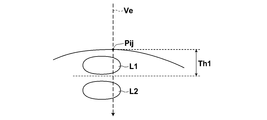
- the label display determination unit 20 uses Pij as the pixel that is the surface of the object on the three-dimensional image V0, and the pixels in all structures to which a certain pixel Pij and a label are assigned on the light vector of the three-dimensional image V0. The distance from Li is calculated.
- a pixel Li_min that minimizes the distance from the pixel Pij in the structure is obtained, and the calculated distance Dmin from the pixel Pij for the minimum point Li_min is a threshold Th1 (for example, 1 cm). Compare with When the distance Dmin is equal to or smaller than the threshold value Th1, a label is displayed for the structure Li.
- FIG. 2 is a diagram for explaining the process of determining the label to be displayed.
- the image is shown two-dimensionally for the sake of explanation.
- structures L1 and L2 with labels are present in this order on a light vector Ve passing through a point Pij on the surface of the object. Then, on the light vector Ve, when the distance from the surface pixel Pij to the structure L1 is equal to or less than the threshold value Th1, and the distance to the structure L2 exceeds the threshold value Th1, it is given to the structure L1.
- Th1 the threshold value
- the above processing is performed on all pixels (x, y) that are the surface of the object on the projection plane, thereby creating a label map that defines whether or not to display a label on the projection plane. It is preferable that this label map indicates 1 for each of the pixels (x, y) on the projection plane when the label is displayed and 0 otherwise. Then, in the label map, connected component processing is performed on a pixel having a value of 1, and a connected component including pixels having a value of 1 is generated. Then, the number of pixels is counted for each connected component, and when the number of pixels is greater than or equal to a threshold Th2 (for example, 100), the region corresponding to the connected component is given to the structure corresponding to the connected component. Decide to display the label.
- a threshold Th2 for example, 100
- the label display control unit 22 displays the label assigned to the structure corresponding to the connected component, superimposed on the VR image being displayed, for the connected component determined to display the label.
- the display position of the label may be any position in the connected component area where the label is displayed. However, if the center of gravity of the connected component exists in the connected component, the position of the center of gravity is at that position. If not present in the connected component, a label is displayed at a position within the connected component region closest to the center of gravity position.
- the label may be displayed as it is at the display position, but it is preferable to display it by drawing a reference line from the display position. Further, when a plurality of labels are to be displayed, it is preferable to display in a range that radiates from the center of the VR image (that is, the center of the projection plane).
- the display positions of the labels may overlap.
- the display of the label is controlled so that all the labels can be confirmed simultaneously by moving the display position with the larger connected component area to a position where the labels do not overlap.
- the input unit 24 includes a known input device such as a keyboard and a mouse.
- the display unit 26 includes a known display device such as a liquid crystal or a CRT.
- FIG. 3 is a flowchart showing processing performed in the present embodiment. It is assumed that the three-dimensional image V0 is acquired by the image acquisition unit 10 and is stored in the storage unit 12 after being given a label by the label applying unit 16.
- the image display control unit 18 displays, on the display unit 26, a VR image on which the structure designated by the user is projected for the three-dimensional image V0 (step ST1).
- the label display determination unit 20 generates a label map as described above, further determines the label to be displayed by performing connected component processing (step ST2), and the label display control unit 22 displays the label on the VR image. (Step ST3).
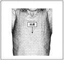
- FIG. 4 is a diagram showing a state where a label is displayed on the VR image.
- the body surface is made opaque and a VR image is displayed. Therefore, as shown in FIG. 4, a leader line is drawn from the center of gravity position of the body surface and the label “skin” is displayed. The At this time, since the body surface is projected on substantially the entire surface of the VR image, a lead line is drawn from a substantially center position of the VR image and a label is displayed. If the body surface is opaque, the internal organs are not visualized.
- step ST4 it is determined whether or not an instruction to change the opacity or the line of sight has been made. If step ST4 is affirmed, the process returns to step ST2, and the processes of step ST2 and step ST3 are repeated.
- the body surface gradually changes from translucent to transparent in the VR image, and the light rays on the projection surface change the body surface.
- the VR image in which the lung region and the bronchus are projected on the projection plane is displayed in order to pass through the lung region and the surface of the bronchus.
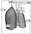
- each of the five lobes of the lung region and the bronchus are labeled, and the lung region and the surface of the bronchus are displayed as VR images. Therefore, as shown in FIG. A label is assigned to each of the five lobes and bronchi constituting the region.
- the labels are displayed with the lead lines radially drawn from the center of each VR image and the center of gravity of the bronchus as a reference.
- the displayed portion disappears for the upper right lobe, so that a VR image including a bronchial branch hidden by the upper right lobe is obtained. Is displayed.
- the label is not displayed for the upper right lobe, but the anatomical nomenclature B1 to B3 given to the bronchus to be displayed in VR and the pulmonary nodules found in the bronchi
- the label of the assigned observation is displayed.
- the lower left lobe is divided into two regions by the bronchus.
- the size of the connected component (having a value of 1) corresponding to the lower left lobe is compared, a label is given to the center of gravity of the larger area, and the smaller area is labeled.
- a translucent label is given to the center of gravity position.
- FIG. 7 the periphery of the translucent label is indicated by a broken line. It should be noted that a label may be applied only to the larger region without labeling the smaller region.
- FIG. 8 the state which changed the eyes
- step ST4 it is determined whether an end instruction has been issued (step ST5). If step ST5 is denied, the process returns to step ST4. If step ST5 is affirmed, the process ends.
- the label to be displayed is determined from the plurality of labels based on the opacity, and the label determined to be displayed corresponds to the structure. And a VR display together with the three-dimensional image V0. For this reason, the user can control the display of the label given to the three-dimensional image V0 without any work, thereby reducing the burden on the user when displaying the label.
- pulmonary arteries, pulmonary veins, ribs, spines, and the like may be further extracted and labeled.
- the label to be displayed may be determined and superimposed on the VR image in the same manner as described above.
- the processing for displaying the VR image of the lung region has been described.
- the present invention can also be applied to the case of extracting the heart and displaying the VR image of the heart region.
- the present invention can also be applied to the case where a VR image of the abdominal three-dimensional image V0 is displayed.
- the target is a liver region
- the liver region, hepatic artery, hepatic vein, portal vein, and tumor are extracted from the three-dimensional image V0, and each is labeled, and is displayed when the VR image is displayed.
- a label to be displayed may be determined based on the opacity of the structure.
- the heart region may be extracted by estimating the signal value range in which the heart exists in the three-dimensional image V0 and performing threshold processing using the value.
- the CT value range in which the liver exists in the three-dimensional image V0 is estimated, threshold processing is performed using the value, and a morphology filter is applied to the extracted region.
- a method of detecting a contrast pattern of a liver region using a plurality of liver phase images taken in time series and extracting a liver region using the same ““ A Liver Level Set ( LLS) Algorithm for Extracting Liver's Volume Containing Disions Regions Automatically ”, IJCSNS International Journal of Computer Science and Network Security, VOL.8 No.12, December 2008 '' and '' Healer region using Level ⁇ ⁇ set method
- the level set method described in “Development and evaluation of area extraction method”, Journal of Computer Aided Diagnosis Society, Vol.7, No.4-2, Jun. 2003 ” can be used.
- the method for extracting the liver region is not limited to these methods, and any method can be used.
- a target tissue having a linear structure described in Japanese Patent Application Laid-Open No. 2010-220742 is used as a target tissue having a linear structure described in Japanese Patent Application Laid-Open No. 2010-220742.
- a method of automatically distinguishing and extracting blood vessels described in JP 2011-212314 A can be used.
- each node is determined for each node based on the feature of extending in a direction away from each starting portion of the first and second linear structures while repeating branching.
- a method of creating a tree structure by connecting each node from each of the second root nodes corresponding to the root node of the structure can be used.
- the first and second linear structures are the hepatic artery and hepatic vein in the liver, so that the hepatic artery and hepatic vein can be distinguished and extracted.
- the first and second linear structures are the portal vein and hepatic artery or hepatic vein, so that the portal vein and hepatic artery or hepatic vein can be distinguished and extracted.
- the starting part may be specified by an arbitrary method, and the root node corresponding to the starting part may be specified by a known method based on the starting part.
- the starting part may be designated on the displayed image by an input device such as a mouse, and the starting point is obtained by machine learning a plurality of teacher data representing a predetermined structure whose starting part is known. It may further include a starting part detecting unit for detecting the part, and may be detected by the starting part detecting unit. Note that various known methods of extracting root nodes by machine learning of teacher data can be used. It is conceivable to detect the part.
- a technique using Voxel classification described in "Liver tumors segmentation from CTA images images using class voxels classification and affineity constraints, propagation, Int JJ CARS, 2010, etc. can be used.
- the method for extracting the hepatic artery, hepatic vein, portal vein, and tumor is not limited to these methods, and any method can be used.
- a label including a character string is displayed.
- an arrow indicating the position of the tumor may be displayed as a label.
- the present invention can also be applied to the case where a label is added to the three-dimensional image of FIG.
Landscapes
- Engineering & Computer Science (AREA)
- Physics & Mathematics (AREA)
- Health & Medical Sciences (AREA)
- Life Sciences & Earth Sciences (AREA)
- Theoretical Computer Science (AREA)
- General Physics & Mathematics (AREA)
- Medical Informatics (AREA)
- Computer Graphics (AREA)
- Radiology & Medical Imaging (AREA)
- Nuclear Medicine, Radiotherapy & Molecular Imaging (AREA)
- General Health & Medical Sciences (AREA)
- Molecular Biology (AREA)
- High Energy & Nuclear Physics (AREA)
- Heart & Thoracic Surgery (AREA)
- Pathology (AREA)
- Surgery (AREA)
- Animal Behavior & Ethology (AREA)
- Optics & Photonics (AREA)
- Public Health (AREA)
- Veterinary Medicine (AREA)
- Biomedical Technology (AREA)
- Computer Hardware Design (AREA)
- General Engineering & Computer Science (AREA)
- Software Systems (AREA)
- Biophysics (AREA)
- Human Computer Interaction (AREA)
- Quality & Reliability (AREA)
- Computer Vision & Pattern Recognition (AREA)
- Apparatus For Radiation Diagnosis (AREA)
- Image Generation (AREA)
Abstract
Description
3次元画像をボリュームレンダリング表示する画像表示制御手段と、
ボリュームレンダリング表示される3次元画像の不透明度に基づいて、複数のラベルのうち、表示するラベルを決定するラベル表示決定手段と、
表示すると決定されたラベルを対応する構造物に付与して、ボリュームレンダリング表示される3次元画像とともに表示するラベル表示制御手段とを備えたことを特徴とするものである。
3次元画像をボリュームレンダリング表示し、
ボリュームレンダリング表示される3次元画像の不透明度に基づいて、複数のラベルのうち、表示するラベルを決定し、
表示すると決定されたラベルを対応する構造物に付与して、ボリュームレンダリング表示される3次元画像とともに表示することを特徴とするものである。
Claims (8)
- 複数の構造物からなる物体の3次元画像であって、該物体に含まれる複数の構造物のそれぞれにラベルが付与されてなる3次元画像を表示する3次元画像表示装置であって、
前記3次元画像をボリュームレンダリング表示する画像表示制御手段と、
前記ボリュームレンダリング表示される前記3次元画像の不透明度に基づいて、前記複数のラベルのうち、表示するラベルを決定するラベル表示決定手段と、
前記表示すると決定されたラベルを対応する構造物に付与して、前記ボリュームレンダリング表示される3次元画像とともに表示するラベル表示制御手段とを備えたことを特徴とする3次元画像表示装置。 - 前記ラベル表示決定手段は、前記3次元画像において、前記不透明度によって不透明となる位置と、前記ラベルが付与された前記構造物との距離が特定の値以下の場合に、該特定の値以下となる構造物に付与されたラベルを表示すると決定する手段であることを特徴とする請求項1記載の3次元画像表示装置。
- 前記ラベル表示制御手段は、前記表示すると決定されたラベルが複数の前記構造物に付与されたものである場合、前記構造物毎に前記ラベルを表示する位置を制御する手段であることを特徴とする請求項1または2記載の3次元画像表示装置。
- 前記ラベル表示制御手段は、同一のラベルを表示する前記構造物が複数の部分に分断されて、前記ボリュームレンダリング表示される前記3次元画像に存在する場合、特定面積以上となる部分にのみ前記ラベルを付与して表示する手段であることを特徴とする請求項1から3のいずれか1項記載の3次元画像表示装置。
- 前記ラベル表示制御手段は、同一のラベルを表示する前記特造物が複数の部分に分断されて、前記ボリュームレンダリング表示される前記3次元画像に存在する場合、最大面積となる部分にのみ前記ラベルを付与して表示する手段であることを特徴とする請求項1から3のいずれか1項記載の3次元画像表示装置。
- 前記3次元画像にラベルを付与するラベル付与手段をさらに備えたことを特徴とする請求項1から4のいずれか1項記載の3次元画像表示装置。
- 複数の構造物からなる物体の3次元画像であって、該物体に含まれる複数の構造物のそれぞれにラベルが付与されてなる3次元画像を表示する3次元画像表示方法であって、
前記3次元画像をボリュームレンダリング表示し、
前記ボリュームレンダリング表示される前記3次元画像の不透明度に基づいて、前記複数のラベルのうち、表示するラベルを決定し、
前記表示すると決定されたラベルを対応する構造物に付与して、前記ボリュームレンダリング表示される3次元画像とともに表示することを特徴とする3次元画像表示方法。 - 複数の構造物からなる物体の3次元画像であって、該物体に含まれる複数の構造物のそれぞれにラベルが付与されてなる3次元画像を表示する3次元画像表示方法をコンピュータに実行させるためのプログラムであって、
前記3次元画像をボリュームレンダリング表示する手順と、
前記ボリュームレンダリング表示される前記3次元画像の不透明度に基づいて、前記複数のラベルのうち、表示するラベルを決定する手順と、
前記表示すると決定されたラベルを対応する構造物に付与して、前記ボリュームレンダリング表示される3次元画像とともに表示する手順とをコンピュータに実行させることを特徴とするプログラム。
Priority Applications (7)
| Application Number | Priority Date | Filing Date | Title |
|---|---|---|---|
| EP13837633.0A EP2896368A4 (en) | 2012-09-13 | 2013-09-09 | DEVICE AND METHOD FOR DISPLAYING THREE-DIMENSIONAL PICTURES AND PROGRAM |
| CA2884679A CA2884679A1 (en) | 2012-09-13 | 2013-09-09 | Three-dimensional image display apparatus, method, and program |
| AU2013317201A AU2013317201A1 (en) | 2012-09-13 | 2013-09-09 | Device and method for displaying three-dimensional image, and program |
| CN201380047366.8A CN104619258A (zh) | 2012-09-13 | 2013-09-09 | 三维图像显示装置、方法及程序 |
| BR112015005240A BR112015005240A2 (pt) | 2012-09-13 | 2013-09-09 | aparelho de exibição de imagem tridimensional, método e programa |
| US14/644,386 US9495794B2 (en) | 2012-09-13 | 2015-03-11 | Three-dimensional image display apparatus, method, and program |
| IN2504DEN2015 IN2015DN02504A (ja) | 2012-09-13 | 2015-03-27 |
Applications Claiming Priority (2)
| Application Number | Priority Date | Filing Date | Title |
|---|---|---|---|
| JP2012-201581 | 2012-09-13 | ||
| JP2012201581A JP6080249B2 (ja) | 2012-09-13 | 2012-09-13 | 3次元画像表示装置および方法並びにプログラム |
Related Child Applications (1)
| Application Number | Title | Priority Date | Filing Date |
|---|---|---|---|
| US14/644,386 Continuation US9495794B2 (en) | 2012-09-13 | 2015-03-11 | Three-dimensional image display apparatus, method, and program |
Publications (1)
| Publication Number | Publication Date |
|---|---|
| WO2014041791A1 true WO2014041791A1 (ja) | 2014-03-20 |
Family
ID=50277933
Family Applications (1)
| Application Number | Title | Priority Date | Filing Date |
|---|---|---|---|
| PCT/JP2013/005328 Ceased WO2014041791A1 (ja) | 2012-09-13 | 2013-09-09 | 3次元画像表示装置および方法並びにプログラム |
Country Status (9)
| Country | Link |
|---|---|
| US (1) | US9495794B2 (ja) |
| EP (1) | EP2896368A4 (ja) |
| JP (1) | JP6080249B2 (ja) |
| CN (1) | CN104619258A (ja) |
| AU (1) | AU2013317201A1 (ja) |
| BR (1) | BR112015005240A2 (ja) |
| CA (1) | CA2884679A1 (ja) |
| IN (1) | IN2015DN02504A (ja) |
| WO (1) | WO2014041791A1 (ja) |
Families Citing this family (33)
| Publication number | Priority date | Publication date | Assignee | Title |
|---|---|---|---|---|
| JP6134986B2 (ja) | 2014-09-01 | 2017-05-31 | 富士フイルム株式会社 | 医用画像計測装置およびその作動方法並びに医用画像計測プログラム |
| JP6530811B2 (ja) * | 2015-05-14 | 2019-06-12 | オリンパス株式会社 | 画像処理装置 |
| JP6827706B2 (ja) * | 2015-09-09 | 2021-02-10 | キヤノン株式会社 | 情報処理装置及びその方法、情報処理システム、コンピュータプログラム |
| JP6396597B2 (ja) * | 2015-09-09 | 2018-09-26 | 富士フイルム株式会社 | マッピング画像表示制御装置および方法並びにプログラム |
| WO2017043194A1 (ja) * | 2015-09-09 | 2017-03-16 | 富士フイルム株式会社 | マッピング画像表示制御装置および方法並びにプログラム |
| JP6496698B2 (ja) * | 2015-10-30 | 2019-04-03 | 株式会社Aze | 医用画像処理装置、その制御方法、及びプログラム |
| WO2017073703A1 (ja) | 2015-10-30 | 2017-05-04 | キヤノン株式会社 | 医用画像処理装置、その制御方法、及びプログラム |
| CN107038750A (zh) * | 2016-02-03 | 2017-08-11 | 上海源胜文化传播有限公司 | 一种三维人体模型生成系统及其方法 |
| US10223590B2 (en) * | 2016-08-01 | 2019-03-05 | Qualcomm Incorporated | Methods and systems of performing adaptive morphology operations in video analytics |
| JP6702902B2 (ja) * | 2017-02-24 | 2020-06-03 | 富士フイルム株式会社 | マッピング画像表示制御装置および方法並びにプログラム |
| JP6983573B2 (ja) * | 2017-08-09 | 2021-12-17 | キヤノン株式会社 | 画像処理装置、画像処理方法およびプログラム |
| WO2019045144A1 (ko) * | 2017-08-31 | 2019-03-07 | (주)레벨소프트 | 의료용 항법 장치를 위한 의료 영상 처리 장치 및 의료 영상 처리 방법 |
| CN108121440A (zh) * | 2017-09-30 | 2018-06-05 | 苏州美房云客软件科技股份有限公司 | 存储装置、计算机设备、虚拟选房系统及其标签设定方法 |
| CN107895400A (zh) * | 2017-11-09 | 2018-04-10 | 深圳赛隆文化科技有限公司 | 一种虚拟现实的三维小区域物体渲染模拟方法及装置 |
| WO2019150717A1 (ja) * | 2018-01-30 | 2019-08-08 | 富士フイルム株式会社 | 葉間膜表示装置、方法およびプログラム |
| CN108711193A (zh) * | 2018-05-04 | 2018-10-26 | 北京雅森科技发展有限公司 | 一种显示脑部病灶区标签的方法 |
| DK180640B1 (en) | 2018-05-07 | 2021-11-09 | Apple Inc | Devices and methods of measurement using augmented reality |
| JP7034306B2 (ja) * | 2018-08-31 | 2022-03-11 | 富士フイルム株式会社 | 領域分割装置、方法およびプログラム、類似度決定装置、方法およびプログラム、並びに特徴量導出装置、方法およびプログラム |
| US10785413B2 (en) | 2018-09-29 | 2020-09-22 | Apple Inc. | Devices, methods, and graphical user interfaces for depth-based annotation |
| CN110213640B (zh) * | 2019-06-28 | 2021-05-14 | 香港乐蜜有限公司 | 虚拟物品的生成方法、装置及设备 |
| US11227446B2 (en) | 2019-09-27 | 2022-01-18 | Apple Inc. | Systems, methods, and graphical user interfaces for modeling, measuring, and drawing using augmented reality |
| US11003308B1 (en) | 2020-02-03 | 2021-05-11 | Apple Inc. | Systems, methods, and graphical user interfaces for annotating, measuring, and modeling environments |
| US12307066B2 (en) | 2020-03-16 | 2025-05-20 | Apple Inc. | Devices, methods, and graphical user interfaces for providing computer-generated experiences |
| US11727650B2 (en) | 2020-03-17 | 2023-08-15 | Apple Inc. | Systems, methods, and graphical user interfaces for displaying and manipulating virtual objects in augmented reality environments |
| EP3940651A1 (en) * | 2020-07-16 | 2022-01-19 | Fraunhofer-Gesellschaft zur Förderung der angewandten Forschung eingetragener Verein | Direct volume rendering apparatus |
| JP7107590B2 (ja) * | 2020-09-15 | 2022-07-27 | 株式会社根本杏林堂 | 医用画像表示端末および医用画像表示プログラム |
| US11615595B2 (en) | 2020-09-24 | 2023-03-28 | Apple Inc. | Systems, methods, and graphical user interfaces for sharing augmented reality environments |
| CN112529976B (zh) * | 2020-11-26 | 2024-06-07 | 上海商汤智能科技有限公司 | 目标显示方法及装置、电子设备和存储介质 |
| CN112768016A (zh) * | 2021-01-26 | 2021-05-07 | 马元 | 基于肺部临床影像的临床教学方法和系统 |
| EP4327293A1 (en) | 2021-04-18 | 2024-02-28 | Apple Inc. | Systems, methods, and graphical user interfaces for adding effects in augmented reality environments |
| US11941764B2 (en) | 2021-04-18 | 2024-03-26 | Apple Inc. | Systems, methods, and graphical user interfaces for adding effects in augmented reality environments |
| EP4227887A1 (en) * | 2022-02-10 | 2023-08-16 | Siemens Healthcare GmbH | Dynamic layout optimization of annotation labels in volume rendering |
| US12469207B2 (en) | 2022-05-10 | 2025-11-11 | Apple Inc. | Systems, methods, and graphical user interfaces for scanning and modeling environments |
Citations (9)
| Publication number | Priority date | Publication date | Assignee | Title |
|---|---|---|---|---|
| JP2001195610A (ja) * | 2000-01-12 | 2001-07-19 | Toshiba Corp | 画像処理装置 |
| JP2004174248A (ja) * | 2002-11-26 | 2004-06-24 | Ge Medical Systems Information Technologies Inc | 直交画像のラベリングの方法及びシステム |
| JP2010500089A (ja) | 2006-08-11 | 2010-01-07 | コーニンクレッカ フィリップス エレクトロニクス エヌ ヴィ | 効率的診断のための解剖構造に関係した画像コンテキスト依存のアプリケーション |
| JP2010148866A (ja) * | 2008-11-21 | 2010-07-08 | Toshiba Corp | 画像処理装置及び画像処理方法 |
| JP2010220742A (ja) | 2009-03-23 | 2010-10-07 | Fujifilm Corp | 画像処理装置および方法並びにプログラム |
| JP2011098195A (ja) * | 2009-10-08 | 2011-05-19 | Fujifilm Corp | 構造物検出装置および方法ならびにプログラム |
| JP2011206168A (ja) | 2010-03-29 | 2011-10-20 | Fujifilm Corp | 観察支援システムおよび方法並びにプログラム |
| JP2011212314A (ja) | 2010-03-31 | 2011-10-27 | Fujifilm Corp | 血管表示制御装置および方法、並びにプログラム |
| JP2012075645A (ja) * | 2010-09-30 | 2012-04-19 | Toshiba Corp | 医用画像診断装置、及び医用画像診断装置の制御プログラム |
Family Cites Families (16)
| Publication number | Priority date | Publication date | Assignee | Title |
|---|---|---|---|---|
| US6331116B1 (en) * | 1996-09-16 | 2001-12-18 | The Research Foundation Of State University Of New York | System and method for performing a three-dimensional virtual segmentation and examination |
| US6411299B1 (en) * | 1999-12-30 | 2002-06-25 | Ge Medical Systems Global Technology Company, Llc | Processing text for display on medical images |
| US6904392B1 (en) * | 2000-10-13 | 2005-06-07 | Dassault Systemes | Annotation management |
| JP2005148409A (ja) | 2003-11-14 | 2005-06-09 | Fuji Xerox Co Ltd | 導電性トナー及びこれを用いた現像装置並びに画像形成装置 |
| JP2005149409A (ja) | 2003-11-19 | 2005-06-09 | Canon Inc | 画像再生方法及び装置 |
| JP5323486B2 (ja) * | 2005-10-21 | 2013-10-23 | コーニンクレッカ フィリップス エヌ ヴェ | レンダリング方法及び装置 |
| EP2162862A2 (en) * | 2007-06-22 | 2010-03-17 | Koninklijke Philips Electronics N.V. | Systems and methods for labeling 3-d volume images on a 2-d display of an ultrasonic imaging system |
| US8285017B2 (en) * | 2008-09-23 | 2012-10-09 | Edda Technology, Inc. | Methods for interactive labeling of tubular structures in medical imaging |
| US8310494B2 (en) * | 2008-09-30 | 2012-11-13 | Apple Inc. | Method for reducing graphics rendering failures |
| US20110188715A1 (en) * | 2010-02-01 | 2011-08-04 | Microsoft Corporation | Automatic Identification of Image Features |
| US9256982B2 (en) * | 2010-03-17 | 2016-02-09 | Microsoft Technology Licensing, Llc | Medical image rendering |
| US8625869B2 (en) * | 2010-05-21 | 2014-01-07 | Siemens Medical Solutions Usa, Inc. | Visualization of medical image data with localized enhancement |
| US20120139915A1 (en) * | 2010-06-07 | 2012-06-07 | Masahiro Muikaichi | Object selecting device, computer-readable recording medium, and object selecting method |
| CN103188998B (zh) * | 2010-11-12 | 2015-03-04 | 株式会社日立医疗器械 | 医用图像显示装置以及医用图像显示方法 |
| JP5369078B2 (ja) * | 2010-11-26 | 2013-12-18 | 富士フイルム株式会社 | 医用画像処理装置および方法、並びにプログラム |
| JP6000672B2 (ja) * | 2011-07-19 | 2016-10-05 | 東芝メディカルシステムズ株式会社 | 画像処理システム、画像保管装置及び医用画像診断装置 |
-
2012
- 2012-09-13 JP JP2012201581A patent/JP6080249B2/ja active Active
-
2013
- 2013-09-09 CA CA2884679A patent/CA2884679A1/en active Pending
- 2013-09-09 AU AU2013317201A patent/AU2013317201A1/en not_active Abandoned
- 2013-09-09 BR BR112015005240A patent/BR112015005240A2/pt not_active IP Right Cessation
- 2013-09-09 CN CN201380047366.8A patent/CN104619258A/zh active Pending
- 2013-09-09 EP EP13837633.0A patent/EP2896368A4/en not_active Ceased
- 2013-09-09 WO PCT/JP2013/005328 patent/WO2014041791A1/ja not_active Ceased
-
2015
- 2015-03-11 US US14/644,386 patent/US9495794B2/en active Active
- 2015-03-27 IN IN2504DEN2015 patent/IN2015DN02504A/en unknown
Patent Citations (9)
| Publication number | Priority date | Publication date | Assignee | Title |
|---|---|---|---|---|
| JP2001195610A (ja) * | 2000-01-12 | 2001-07-19 | Toshiba Corp | 画像処理装置 |
| JP2004174248A (ja) * | 2002-11-26 | 2004-06-24 | Ge Medical Systems Information Technologies Inc | 直交画像のラベリングの方法及びシステム |
| JP2010500089A (ja) | 2006-08-11 | 2010-01-07 | コーニンクレッカ フィリップス エレクトロニクス エヌ ヴィ | 効率的診断のための解剖構造に関係した画像コンテキスト依存のアプリケーション |
| JP2010148866A (ja) * | 2008-11-21 | 2010-07-08 | Toshiba Corp | 画像処理装置及び画像処理方法 |
| JP2010220742A (ja) | 2009-03-23 | 2010-10-07 | Fujifilm Corp | 画像処理装置および方法並びにプログラム |
| JP2011098195A (ja) * | 2009-10-08 | 2011-05-19 | Fujifilm Corp | 構造物検出装置および方法ならびにプログラム |
| JP2011206168A (ja) | 2010-03-29 | 2011-10-20 | Fujifilm Corp | 観察支援システムおよび方法並びにプログラム |
| JP2011212314A (ja) | 2010-03-31 | 2011-10-27 | Fujifilm Corp | 血管表示制御装置および方法、並びにプログラム |
| JP2012075645A (ja) * | 2010-09-30 | 2012-04-19 | Toshiba Corp | 医用画像診断装置、及び医用画像診断装置の制御プログラム |
Non-Patent Citations (10)
| Title |
|---|
| C. SCHNEIDER ET AL.: "Automated lung nodule detection and segmentation", MEDICAL IMAGING, PROC. OF SPIE, vol. 7260, 2009 |
| J. MASUMOTO ET AL.: "Automated Liver Segmentation Method for Dynamic CT Data Using Non-Rigid Registration", JOURNAL OF COMPUTER AIDED DIAGNOSIS OF MEDICAL IMAGES, vol. 7, no. 4-1, 2003 |
| K. MORI ET AL.: "A method for automated nomenclature of bronchial branches extracted from CT images", INTERNATIONAL CONGRESS SERIED, vol. 1281, 2005, pages 86 - 91 |
| M. FREIMAN ET AL.: "Liver tumors segmentation from CTA images using voxels classification and affinity constraint propagation", INT J CARS, 2010 |
| N. KAWAMURA ET AL.: "Examination of Bronchus Extraction Algorithm using Multi Slice CT Images", THE INSTITUTE OF ELECTRONICS, INFORMATION AND COMMUNICATION ENGINEERS, TECHNICAL REPORT, MBE, ME AND BIO-CYBERNETICS, vol. 105, no. 221, 2005, pages 11 - 14 |
| P.S. SULAIMAN ET AL.: "A Liver Level Set (LLS) Algorithm for Extracting Liver's Volume Containing Disconnected Regions Automatically", IJCSNS INTERNATIONAL JOURNAL OF COMPUTER SCIENCE AND NETWORK SECURITY, vol. 8, no. 12, 2008 |
| See also references of EP2896368A4 |
| T. HITOSUGI ET AL.: "Development of a liver extraction method using a level set method and its performance evaluation", COMPUTER AIDED DIAGNOSIS OF MEDICAL IMAGES, vol. 7, no. 4-2, 2003 |
| Y SATO ET AL.: "Extraction of Lung Lobes in X-ray CT images and its Application to Evaluation of Heavy Ion Radiation Therapy", MEDICAL IMAGING TECHNOLOGY, vol. 22, no. 5, 2004 |
| Y. LI ET AL.: "Interactive Segmentation of Lung Nodules using AdaBoost and Graph Cuts", FOURTH INTERNATIONAL WORKSHOP ON PULMONARY IMAGE ANALYSIS, pages 125 - 133 |
Also Published As
| Publication number | Publication date |
|---|---|
| BR112015005240A2 (pt) | 2017-07-04 |
| CN104619258A (zh) | 2015-05-13 |
| IN2015DN02504A (ja) | 2015-09-11 |
| US20150187118A1 (en) | 2015-07-02 |
| AU2013317201A1 (en) | 2015-04-30 |
| EP2896368A1 (en) | 2015-07-22 |
| CA2884679A1 (en) | 2014-03-20 |
| EP2896368A4 (en) | 2016-06-22 |
| JP6080249B2 (ja) | 2017-02-15 |
| US9495794B2 (en) | 2016-11-15 |
| JP2014054428A (ja) | 2014-03-27 |
Similar Documents
| Publication | Publication Date | Title |
|---|---|---|
| JP6080249B2 (ja) | 3次元画像表示装置および方法並びにプログラム | |
| JP6080248B2 (ja) | 3次元画像表示装置および方法並びにプログラム | |
| Van Rikxoort et al. | Automated segmentation of pulmonary structures in thoracic computed tomography scans: a review | |
| JP6877868B2 (ja) | 画像処理装置、画像処理方法および画像処理プログラム | |
| Ritter et al. | Medical image analysis | |
| JP4728627B2 (ja) | Ct血管造影法における構造を領域分割する方法及び装置 | |
| JP5584006B2 (ja) | 投影画像生成装置、投影画像生成プログラムおよび投影画像生成方法 | |
| EP2856428B1 (en) | Segmentation highlighter | |
| JP5934071B2 (ja) | 管状構造の最短経路探索装置および方法並びにプログラム | |
| CN112862833A (zh) | 血管分段方法、电子装置和存储介质 | |
| CN106204733A (zh) | 肝脏和肾脏ct图像联合三维构建系统 | |
| CN113177945A (zh) | 用于将分割图链接到体数据的系统和方法 | |
| EP2638525A1 (en) | Identifying individual sub-regions of the cardiovascular system for calcium scoring | |
| EP1859404B1 (en) | Identifying abnormal tissue in images of computed tomography | |
| CN111563876A (zh) | 一种医学影像的获取方法、显示方法 | |
| Ropinski et al. | Multimodal vessel visualization of mouse aorta PET/CT scans | |
| Chi et al. | Stenosis detection and quantification on cardiac CTCA using panoramic MIP of coronary arteries | |
| Krass et al. | Computer-assisted image-based risk analysis and planning in lung surgery-a review | |
| CN111563877B (zh) | 一种医学影像的生成方法及装置、显示方法及存储介质 | |
| US10832492B2 (en) | Panoramic visualization of coronary arterial tree | |
| Viola et al. | Illustrated Ultrasound for Multimodal Data Interpretation of Liver Examinations. | |
| Pant et al. | Enhancing Liver Biopsy Simulations: 3D Model Development, Endoscopic Imaging, and Needle Tracking | |
| Tachiki et al. | Semi-automated measurement of blood vessel diameter for arteriosclerosis retinae classification | |
| Kamal | Investigation of in Vivo Cardiac Chambers Composite Rendering | |
| CN120280090A (zh) | 手术规划系统、方法、电子设备及存储介质 |
Legal Events
| Date | Code | Title | Description |
|---|---|---|---|
| 121 | Ep: the epo has been informed by wipo that ep was designated in this application |
Ref document number: 13837633 Country of ref document: EP Kind code of ref document: A1 |
|
| ENP | Entry into the national phase |
Ref document number: 2884679 Country of ref document: CA |
|
| NENP | Non-entry into the national phase |
Ref country code: DE |
|
| WWE | Wipo information: entry into national phase |
Ref document number: 2013837633 Country of ref document: EP |
|
| REG | Reference to national code |
Ref country code: BR Ref legal event code: B01A Ref document number: 112015005240 Country of ref document: BR |
|
| ENP | Entry into the national phase |
Ref document number: 2013317201 Country of ref document: AU Date of ref document: 20130909 Kind code of ref document: A |
|
| ENP | Entry into the national phase |
Ref document number: 112015005240 Country of ref document: BR Kind code of ref document: A2 Effective date: 20150309 |
|
| WWW | Wipo information: withdrawn in national office |
Ref document number: 2013837633 Country of ref document: EP |