WO2014041796A1 - リレー溶着検出装置 - Google Patents
リレー溶着検出装置 Download PDFInfo
- Publication number
- WO2014041796A1 WO2014041796A1 PCT/JP2013/005360 JP2013005360W WO2014041796A1 WO 2014041796 A1 WO2014041796 A1 WO 2014041796A1 JP 2013005360 W JP2013005360 W JP 2013005360W WO 2014041796 A1 WO2014041796 A1 WO 2014041796A1
- Authority
- WO
- WIPO (PCT)
- Prior art keywords
- relay
- welding
- power supply
- detection
- leakage
- Prior art date
- Legal status (The legal status is an assumption and is not a legal conclusion. Google has not performed a legal analysis and makes no representation as to the accuracy of the status listed.)
- Ceased
Links
Images



Classifications
-
- H—ELECTRICITY
- H02—GENERATION; CONVERSION OR DISTRIBUTION OF ELECTRIC POWER
- H02H—EMERGENCY PROTECTIVE CIRCUIT ARRANGEMENTS
- H02H3/00—Emergency protective circuit arrangements for automatic disconnection directly responsive to an undesired change from normal electric working condition with or without subsequent reconnection ; integrated protection
- H02H3/16—Emergency protective circuit arrangements for automatic disconnection directly responsive to an undesired change from normal electric working condition with or without subsequent reconnection ; integrated protection responsive to fault current to earth, frame or mass
-
- B—PERFORMING OPERATIONS; TRANSPORTING
- B60—VEHICLES IN GENERAL
- B60L—PROPULSION OF ELECTRICALLY-PROPELLED VEHICLES; SUPPLYING ELECTRIC POWER FOR AUXILIARY EQUIPMENT OF ELECTRICALLY-PROPELLED VEHICLES; ELECTRODYNAMIC BRAKE SYSTEMS FOR VEHICLES IN GENERAL; MAGNETIC SUSPENSION OR LEVITATION FOR VEHICLES; MONITORING OPERATING VARIABLES OF ELECTRICALLY-PROPELLED VEHICLES; ELECTRIC SAFETY DEVICES FOR ELECTRICALLY-PROPELLED VEHICLES
- B60L3/00—Electric devices on electrically-propelled vehicles for safety purposes; Monitoring operating variables, e.g. speed, deceleration or energy consumption
-
- B—PERFORMING OPERATIONS; TRANSPORTING
- B60—VEHICLES IN GENERAL
- B60L—PROPULSION OF ELECTRICALLY-PROPELLED VEHICLES; SUPPLYING ELECTRIC POWER FOR AUXILIARY EQUIPMENT OF ELECTRICALLY-PROPELLED VEHICLES; ELECTRODYNAMIC BRAKE SYSTEMS FOR VEHICLES IN GENERAL; MAGNETIC SUSPENSION OR LEVITATION FOR VEHICLES; MONITORING OPERATING VARIABLES OF ELECTRICALLY-PROPELLED VEHICLES; ELECTRIC SAFETY DEVICES FOR ELECTRICALLY-PROPELLED VEHICLES
- B60L3/00—Electric devices on electrically-propelled vehicles for safety purposes; Monitoring operating variables, e.g. speed, deceleration or energy consumption
- B60L3/0023—Detecting, eliminating, remedying or compensating for drive train abnormalities, e.g. failures within the drive train
- B60L3/0046—Detecting, eliminating, remedying or compensating for drive train abnormalities, e.g. failures within the drive train relating to electric energy storage systems, e.g. batteries or capacitors
-
- B—PERFORMING OPERATIONS; TRANSPORTING
- B60—VEHICLES IN GENERAL
- B60L—PROPULSION OF ELECTRICALLY-PROPELLED VEHICLES; SUPPLYING ELECTRIC POWER FOR AUXILIARY EQUIPMENT OF ELECTRICALLY-PROPELLED VEHICLES; ELECTRODYNAMIC BRAKE SYSTEMS FOR VEHICLES IN GENERAL; MAGNETIC SUSPENSION OR LEVITATION FOR VEHICLES; MONITORING OPERATING VARIABLES OF ELECTRICALLY-PROPELLED VEHICLES; ELECTRIC SAFETY DEVICES FOR ELECTRICALLY-PROPELLED VEHICLES
- B60L3/00—Electric devices on electrically-propelled vehicles for safety purposes; Monitoring operating variables, e.g. speed, deceleration or energy consumption
- B60L3/0023—Detecting, eliminating, remedying or compensating for drive train abnormalities, e.g. failures within the drive train
- B60L3/0069—Detecting, eliminating, remedying or compensating for drive train abnormalities, e.g. failures within the drive train relating to the isolation, e.g. ground fault or leak current
-
- B—PERFORMING OPERATIONS; TRANSPORTING
- B60—VEHICLES IN GENERAL
- B60L—PROPULSION OF ELECTRICALLY-PROPELLED VEHICLES; SUPPLYING ELECTRIC POWER FOR AUXILIARY EQUIPMENT OF ELECTRICALLY-PROPELLED VEHICLES; ELECTRODYNAMIC BRAKE SYSTEMS FOR VEHICLES IN GENERAL; MAGNETIC SUSPENSION OR LEVITATION FOR VEHICLES; MONITORING OPERATING VARIABLES OF ELECTRICALLY-PROPELLED VEHICLES; ELECTRIC SAFETY DEVICES FOR ELECTRICALLY-PROPELLED VEHICLES
- B60L3/00—Electric devices on electrically-propelled vehicles for safety purposes; Monitoring operating variables, e.g. speed, deceleration or energy consumption
- B60L3/04—Cutting off the power supply under fault conditions
-
- B—PERFORMING OPERATIONS; TRANSPORTING
- B60—VEHICLES IN GENERAL
- B60L—PROPULSION OF ELECTRICALLY-PROPELLED VEHICLES; SUPPLYING ELECTRIC POWER FOR AUXILIARY EQUIPMENT OF ELECTRICALLY-PROPELLED VEHICLES; ELECTRODYNAMIC BRAKE SYSTEMS FOR VEHICLES IN GENERAL; MAGNETIC SUSPENSION OR LEVITATION FOR VEHICLES; MONITORING OPERATING VARIABLES OF ELECTRICALLY-PROPELLED VEHICLES; ELECTRIC SAFETY DEVICES FOR ELECTRICALLY-PROPELLED VEHICLES
- B60L53/00—Methods of charging batteries, specially adapted for electric vehicles; Charging stations or on-board charging equipment therefor; Exchange of energy storage elements in electric vehicles
- B60L53/10—Methods of charging batteries, specially adapted for electric vehicles; Charging stations or on-board charging equipment therefor; Exchange of energy storage elements in electric vehicles characterised by the energy transfer between the charging station and the vehicle
- B60L53/14—Conductive energy transfer
-
- B—PERFORMING OPERATIONS; TRANSPORTING
- B60—VEHICLES IN GENERAL
- B60L—PROPULSION OF ELECTRICALLY-PROPELLED VEHICLES; SUPPLYING ELECTRIC POWER FOR AUXILIARY EQUIPMENT OF ELECTRICALLY-PROPELLED VEHICLES; ELECTRODYNAMIC BRAKE SYSTEMS FOR VEHICLES IN GENERAL; MAGNETIC SUSPENSION OR LEVITATION FOR VEHICLES; MONITORING OPERATING VARIABLES OF ELECTRICALLY-PROPELLED VEHICLES; ELECTRIC SAFETY DEVICES FOR ELECTRICALLY-PROPELLED VEHICLES
- B60L53/00—Methods of charging batteries, specially adapted for electric vehicles; Charging stations or on-board charging equipment therefor; Exchange of energy storage elements in electric vehicles
- B60L53/30—Constructional details of charging stations
- B60L53/31—Charging columns specially adapted for electric vehicles
-
- G—PHYSICS
- G01—MEASURING; TESTING
- G01R—MEASURING ELECTRIC VARIABLES; MEASURING MAGNETIC VARIABLES
- G01R31/00—Arrangements for testing electric properties; Arrangements for locating electric faults; Arrangements for electrical testing characterised by what is being tested not provided for elsewhere
- G01R31/50—Testing of electric apparatus, lines, cables or components for short-circuits, continuity, leakage current or incorrect line connections
- G01R31/52—Testing for short-circuits, leakage current or ground faults
-
- G—PHYSICS
- G01—MEASURING; TESTING
- G01R—MEASURING ELECTRIC VARIABLES; MEASURING MAGNETIC VARIABLES
- G01R31/00—Arrangements for testing electric properties; Arrangements for locating electric faults; Arrangements for electrical testing characterised by what is being tested not provided for elsewhere
- G01R31/50—Testing of electric apparatus, lines, cables or components for short-circuits, continuity, leakage current or incorrect line connections
- G01R31/66—Testing of connections, e.g. of plugs or non-disconnectable joints
- G01R31/68—Testing of releasable connections, e.g. of terminals mounted on a printed circuit board
-
- H—ELECTRICITY
- H01—ELECTRIC ELEMENTS
- H01H—ELECTRIC SWITCHES; RELAYS; SELECTORS; EMERGENCY PROTECTIVE DEVICES
- H01H47/00—Circuit arrangements not adapted to a particular application of the relay and designed to obtain desired operating characteristics or to provide energising current
-
- H—ELECTRICITY
- H01—ELECTRIC ELEMENTS
- H01H—ELECTRIC SWITCHES; RELAYS; SELECTORS; EMERGENCY PROTECTIVE DEVICES
- H01H47/00—Circuit arrangements not adapted to a particular application of the relay and designed to obtain desired operating characteristics or to provide energising current
- H01H47/002—Monitoring or fail-safe circuits
-
- H—ELECTRICITY
- H02—GENERATION; CONVERSION OR DISTRIBUTION OF ELECTRIC POWER
- H02H—EMERGENCY PROTECTIVE CIRCUIT ARRANGEMENTS
- H02H7/00—Emergency protective circuit arrangements specially adapted for specific types of electric machines or apparatus or for sectionalised protection of cable or line systems, and effecting automatic switching in the event of an undesired change from normal working conditions
-
- G—PHYSICS
- G01—MEASURING; TESTING
- G01R—MEASURING ELECTRIC VARIABLES; MEASURING MAGNETIC VARIABLES
- G01R31/00—Arrangements for testing electric properties; Arrangements for locating electric faults; Arrangements for electrical testing characterised by what is being tested not provided for elsewhere
- G01R31/005—Testing of electric installations on transport means
- G01R31/006—Testing of electric installations on transport means on road vehicles, e.g. automobiles or trucks
-
- G—PHYSICS
- G01—MEASURING; TESTING
- G01R—MEASURING ELECTRIC VARIABLES; MEASURING MAGNETIC VARIABLES
- G01R31/00—Arrangements for testing electric properties; Arrangements for locating electric faults; Arrangements for electrical testing characterised by what is being tested not provided for elsewhere
- G01R31/327—Testing of circuit interrupters, switches or circuit-breakers
- G01R31/3277—Testing of circuit interrupters, switches or circuit-breakers of low voltage devices, e.g. domestic or industrial devices, such as motor protections, relays, rotation switches
- G01R31/3278—Testing of circuit interrupters, switches or circuit-breakers of low voltage devices, e.g. domestic or industrial devices, such as motor protections, relays, rotation switches of relays, solenoids or reed switches
-
- H—ELECTRICITY
- H01—ELECTRIC ELEMENTS
- H01H—ELECTRIC SWITCHES; RELAYS; SELECTORS; EMERGENCY PROTECTIVE DEVICES
- H01H47/00—Circuit arrangements not adapted to a particular application of the relay and designed to obtain desired operating characteristics or to provide energising current
- H01H47/002—Monitoring or fail-safe circuits
- H01H2047/003—Detecting welded contacts and applying weld break pulses to coil
-
- Y—GENERAL TAGGING OF NEW TECHNOLOGICAL DEVELOPMENTS; GENERAL TAGGING OF CROSS-SECTIONAL TECHNOLOGIES SPANNING OVER SEVERAL SECTIONS OF THE IPC; TECHNICAL SUBJECTS COVERED BY FORMER USPC CROSS-REFERENCE ART COLLECTIONS [XRACs] AND DIGESTS
- Y02—TECHNOLOGIES OR APPLICATIONS FOR MITIGATION OR ADAPTATION AGAINST CLIMATE CHANGE
- Y02T—CLIMATE CHANGE MITIGATION TECHNOLOGIES RELATED TO TRANSPORTATION
- Y02T10/00—Road transport of goods or passengers
- Y02T10/60—Other road transportation technologies with climate change mitigation effect
- Y02T10/70—Energy storage systems for electromobility, e.g. batteries
-
- Y—GENERAL TAGGING OF NEW TECHNOLOGICAL DEVELOPMENTS; GENERAL TAGGING OF CROSS-SECTIONAL TECHNOLOGIES SPANNING OVER SEVERAL SECTIONS OF THE IPC; TECHNICAL SUBJECTS COVERED BY FORMER USPC CROSS-REFERENCE ART COLLECTIONS [XRACs] AND DIGESTS
- Y02—TECHNOLOGIES OR APPLICATIONS FOR MITIGATION OR ADAPTATION AGAINST CLIMATE CHANGE
- Y02T—CLIMATE CHANGE MITIGATION TECHNOLOGIES RELATED TO TRANSPORTATION
- Y02T10/00—Road transport of goods or passengers
- Y02T10/60—Other road transportation technologies with climate change mitigation effect
- Y02T10/7072—Electromobility specific charging systems or methods for batteries, ultracapacitors, supercapacitors or double-layer capacitors
-
- Y—GENERAL TAGGING OF NEW TECHNOLOGICAL DEVELOPMENTS; GENERAL TAGGING OF CROSS-SECTIONAL TECHNOLOGIES SPANNING OVER SEVERAL SECTIONS OF THE IPC; TECHNICAL SUBJECTS COVERED BY FORMER USPC CROSS-REFERENCE ART COLLECTIONS [XRACs] AND DIGESTS
- Y02—TECHNOLOGIES OR APPLICATIONS FOR MITIGATION OR ADAPTATION AGAINST CLIMATE CHANGE
- Y02T—CLIMATE CHANGE MITIGATION TECHNOLOGIES RELATED TO TRANSPORTATION
- Y02T90/00—Enabling technologies or technologies with a potential or indirect contribution to GHG emissions mitigation
- Y02T90/10—Technologies relating to charging of electric vehicles
- Y02T90/12—Electric charging stations
-
- Y—GENERAL TAGGING OF NEW TECHNOLOGICAL DEVELOPMENTS; GENERAL TAGGING OF CROSS-SECTIONAL TECHNOLOGIES SPANNING OVER SEVERAL SECTIONS OF THE IPC; TECHNICAL SUBJECTS COVERED BY FORMER USPC CROSS-REFERENCE ART COLLECTIONS [XRACs] AND DIGESTS
- Y02—TECHNOLOGIES OR APPLICATIONS FOR MITIGATION OR ADAPTATION AGAINST CLIMATE CHANGE
- Y02T—CLIMATE CHANGE MITIGATION TECHNOLOGIES RELATED TO TRANSPORTATION
- Y02T90/00—Enabling technologies or technologies with a potential or indirect contribution to GHG emissions mitigation
- Y02T90/10—Technologies relating to charging of electric vehicles
- Y02T90/14—Plug-in electric vehicles
Definitions
- the present invention relates to a relay welding detection device for detecting welding of a relay provided in a charging path from an external power source to a storage battery.
- a relay circuit for connecting and disconnecting a quick charger and a storage battery connecting junction circuit at the time of charging is used.
- a mechanical relay contact (hereinafter referred to as “relay”) is used for this relay circuit, and the relay may be welded due to on / off at high voltage and high current.
- a relay welding detection circuit for detecting such relay welding is known (for example, see Patent Document 1).
- a DFR (Dead Front Relay) is provided between the charging inlet and the neutral point of the motor, and a voltage sensor is further provided between the charging inlet and the DFR. Moreover, in patent document 1, one side of DFR is set to ON and the other is set to OFF. And in patent document 1, when the voltage sensor detects a voltage, it is judged that the DFR turned OFF is welding.
- Patent Document 2 a battery charger that detects electric leakage on the vehicle side is known (for example, Patent Document 2).
- Patent Document 1 there is a problem that although the welding of the relay can be detected, the leakage cannot be detected.
- Patent Document 2 there is a problem in that although leakage can be detected, welding of the relay cannot be detected.
- the relay welding detection device of Patent Document 1 when leakage is detected by a charger outside the vehicle as shown in Patent Document 2, when detecting leakage, a relay welding detection device is used. Current flows through the voltage sensor. In this case, there is a problem in that it is erroneously detected that there is a leakage even though there is no leakage.
- the relay welding detection apparatus is a relay welding detection apparatus that detects welding of a relay provided in a charging path from an external power source to a storage battery, and the charging path when the relay is turned off during charging stop. And a switch that opens and closes the connection between the external power source and the detection unit based on a current that flows on the external power supply side of the relay.
- the connection between the relay welding detection unit and the external power source is cut off to prevent erroneous detection of the leakage when both the relay welding and the leakage can be detected. Can do.
- the block diagram which shows the structure of the charging system in Embodiment 1 of this invention The flowchart which shows the operation
- the charging system 10 mainly includes a vehicle 150, an external power supply device 160, a cable 170, and a charging plug 180.
- the vehicle 150 travels using the storage battery 152 as a power source.
- the vehicle 150 is an automobile that runs on the electric power of the storage battery 152 such as HEV (Hybrid Electric Vehicle), PEV (Plug-in Electric Vehicle), or EV (Electric Vehicle).
- HEV Hybrid Electric Vehicle
- PEV Plug-in Electric Vehicle
- EV Electric Vehicle
- the external power supply device 160 supplies power to the storage battery 152 via the cable 170 and the charging plug 180 to charge the storage battery 152.
- the external power supply device 160 is a commercial battery or a quick charger provided in a charging station in the city.
- the external power supply device 160 detects a leakage on the vehicle 150 side. External power supply device 160 does not charge vehicle 150 when it detects a leakage.
- the cable 170 connects the external power supply device 160 and the charging plug 180.
- the charging plug 180 can be connected to the power supply connection portion 151. Charging plug 180 supplies power supplied from external power supply device 160 via cable 170 to storage battery 152 via relay welding detection device 100 when connected to power supply connection portion 151.
- the vehicle 150 includes the relay welding detection device 100, a power supply connection unit 151, and a storage battery 152.
- the relay welding detection device 100 detects welding of the power supply side relay 101 and the ground side relay 102.
- the detection result of relay welding detected by the relay welding detection device 100 is displayed on a display unit (not shown) provided in the vehicle 150, for example. The details of the configuration of the relay welding detection apparatus 100 will be described later.
- the power connection 151 is connected to the relay welding detection device 100.
- Power supply connection portion 151 is connected to charging plug 180 to connect charging plug 180 and relay welding detection device 100.
- the power supply connection portion 151 is provided, for example, so as to be exposed on the body surface of the vehicle 150.
- the power supply connection portion 151 is provided with a power supply side terminal 151a and a ground side terminal 151b.
- a positive electrode (+) terminal of the storage battery 152 is connected to the power supply side terminal 151 a via the power supply side relay 101.
- the negative terminal ( ⁇ ) of the storage battery 152 is connected to the ground-side terminal 151b via the ground-side relay 102.
- the storage battery 152 stores electric power supplied from the external power supply device 160 via the cable 170, the charging plug 180, the power supply connection portion 151, and the relay welding detection device 100.
- the storage battery 152 is mounted on the vehicle 150.
- connection disconnection switch 104 is turned off and the connection between the welding detection switch 103 and the external power supply device 160 is disconnected at a time other than when the relay welding is detected.
- the relay welding detection device 100 mainly includes a power supply side relay 101, a ground side relay 102, a welding detection switch 103, a connection cutoff switch 104, a resistor 105, and a control unit 106.
- the welding detection switch 103 and the control unit 106 constitute a detection unit that detects welding of the relay.
- the power supply side relay 101 is provided in a charging path from the external power supply device 160 to the storage battery 152. Specifically, the power supply side relay 101 is inserted in series with a power line connecting the external power supply device 160 and the storage battery 152.
- the charging path is a path from the external power supply device 160 to the storage battery 152 when the storage battery 152 is charged by the external power supply device 160.
- the power supply side relay 101 is turned on by the control of the control unit 106 to connect the external power supply device 160 and the storage battery 152. Further, the power supply side relay 101 is turned off by the control of the control unit 106 to disconnect the connection between the external power supply device 160 and the storage battery 152.
- the ground side relay 102 is provided in a charging path from the external power supply device 160 to the storage battery 152. Specifically, the ground-side relay 101 is inserted in series with a power line connecting the external power supply device 160 and the storage battery 152.
- the ground-side relay 102 is turned on to connect the external power supply device 160 and the storage battery 152 under the control of the control unit 106. In addition, the ground-side relay 102 is turned off and disconnects the connection between the external power supply device 160 and the storage battery 152 under the control of the control unit 106.
- the welding detection switch 103 is connected in parallel to the charging path.
- the welding detection switch 103 is a photocoupler (second photocoupler) having a light emitting diode 103A and a phototransistor 103B.
- the collector terminal of the phototransistor 103B is connected to the voltage detection terminal Vde of the control unit 106.
- the emitter terminal of the phototransistor 103B is connected to the body ground of the vehicle 150.
- the anode terminal of the light emitting diode 103 ⁇ / b> A is connected to the external power supply side of the power supply side relay 101.
- the cathode terminal of the light emitting diode 103 ⁇ / b> A is connected to the connection cutoff switch 104.
- the light emitting diode 103A emits light when a current of a predetermined value or more flows between the power supply side relay 101 and the power supply side terminal 151a or between the ground side relay 102 and the ground side terminal 151b.
- the phototransistor 103B receives light emitted when the light emitting diode 103A emits light and is turned on.
- the welding detection switch 103 connects the voltage detection terminal Vde of the control unit 106 and the body ground of the vehicle 150 when turned on.
- the phototransistor 103B is not conductive (turned off) when the light emitting diode 103A does not emit light.
- the welding detection switch 103 is turned off, the connection between the voltage detection terminal Vde of the control unit 106 and the body ground of the vehicle 150 is disconnected.
- connection cutoff switch 104 is connected in parallel to the charging path, and is inserted in series between the welding detection switch 103 and the power supply connection portion 151.
- the connection cutoff switch 104 connects the external power supply device 160 (or the power supply connection unit 151 when the charging plug 180 is not connected to the power supply connection unit 151) and the welding detection switch 103 according to the control of the control unit 106. Open and close.
- the connection cutoff switch 104 is a photocoupler (first photocoupler) having a light emitting diode 104A and a phototransistor 104B.
- the anode terminal of the light emitting diode 104 ⁇ / b> A is connected to the control terminal Vc ⁇ b> 2 of the control unit 106.
- the cathode terminal of the light emitting diode 104 ⁇ / b> A is connected to the body ground of the vehicle 150.
- the collector terminal of the phototransistor 104B is connected to the cathode terminal of the light emitting diode 103A.
- the emitter terminal of the phototransistor 104B is connected to the external power supply side of the ground-side relay 102.
- the light emitting diode 104A emits light when a control signal of a predetermined level is input from the control terminal Vc2 of the control unit 106.
- the phototransistor 104B receives light emitted when the light emitting diode 104A emits light and is turned on. When the connection cutoff switch 104 is turned on, it connects the welding detection switch 103 and the external power supply device 160.
- the phototransistor 104B is not conductive (turned off) when the light emitting diode 104A does not emit light. That is, when the connection cutoff switch 104 is turned off, the connection between the welding detection switch 103 and the external power supply device 160 is disconnected.
- the resistor 105 is inserted in series between the external power supply side of the power supply side relay 101 and the light emitting diode 103A.
- the control unit 106 outputs a control signal Vryp for performing on / off control of the power supply side relay 101 to the power supply side relay 101.
- the control unit 106 outputs a control signal Vryn for performing on / off control of the ground side relay 102 to the ground side relay 102.
- the control unit 106 turns off the power-side relay 101 or the ground-side relay 102 while charging is stopped, and detects welding of the power-side relay 101 or welding of the ground-side relay 102. At this time, the control unit 106 controls the power supply side based on the current flowing on the external power supply device 160 side from the power supply side relay 101 in the charging path or the current flowing on the external power supply apparatus 160 side from the ground side relay 102 in the charging path. The welding of the relay 101 or the welding of the ground side relay 102 is detected.
- the control unit 106 detects welding of the power supply side relay 101 or the ground side relay 102 based on the voltage detected at the voltage detection terminal Vde to which the collector terminal of the phototransistor 103B is connected. At this time, when the current detected in the phototransistor 103B flows to the phototransistor 103B and the welding detection switch 103 is turned on, the control unit 106 determines that the voltage detected at the voltage detection terminal Vde is lower than the predetermined value. It is determined that the relay 101 or the ground side relay 102 is welded. That is, the control unit 106 detects welding of the power-side relay 101 or welding of the ground-side relay 102 based on detection results of voltages that differ depending on whether the welding detection switch 103 is turned on or off.
- control unit 106 determines that the power supply side relay 101 or the ground side relay 102 is welded when the voltage detected at the voltage detection terminal Vde changes from “H” level to “L” level. A method for detecting welding of the relay will be described later.
- the external power supply device 160 side with respect to the power supply side relay 101 of the charging path is a path k1 between the power supply side relay 101 and the power supply side terminal 151a.
- the external power supply device 160 side of the charging path with respect to the ground side relay 102 is a path k2 between the ground side relay 102 and the ground side terminal 151b.
- the control unit 106 outputs a control signal from the control terminal Vc2 to the light emitting diode 104A to turn on the connection cutoff switch 104. Further, the control unit 106 outputs a control signal from the control terminal Vc2 to the light emitting diode 104A to turn off the connection cutoff switch 104. For example, the control unit 106 outputs a “H” level control signal to the light emitting diode 104A to cause the light emitting diode 104A to emit light, thereby turning on the connection cutoff switch 104. In addition, the control unit 106 outputs a “L” level control signal to the light emitting diode 104A to cause the light emitting diode 104A not to emit light, thereby turning off the connection cutoff switch 104.
- the control unit 106 turns off the connection cutoff switch 104 except when the welding of the power supply side relay 101 and the ground side relay 102 is detected.
- the control unit 106 is electrically insulated from the high voltage side (the external power supply device 160 side) by the welding detection switch 103 and the connection cutoff switch 104. Note that a method for detecting a leakage will be described later.
- the external power supply device 160 mainly includes a power generation unit 161, an input / output unit 162, and a leakage detection unit 163.
- the power generator 161 supplies power to the input / output unit 162.
- the input / output unit 162 is connected to the cable 170, and supplies the power supplied from the power generation unit 161 to the cable 170.
- the leakage detector 163 detects a leakage on the vehicle 150 side.
- the leakage detection unit 163 detects a leakage by detecting a voltage at a predetermined level when the power supply side relay 101 and the ground side relay 102 are turned off and power is supplied from the power supply generation unit 161.
- the leakage detection unit 163 detects the leakage by detecting that the current that should not flow originally flows because the power supply side relay 101 and the ground side relay 102 are turned off.
- the leakage detector 163 detects the current flow that should not flow originally as a change in voltage.
- the power supplied from the power generation unit 161 when detecting a leakage is smaller than the power supplied from the power generation unit 161 during charging.
- control unit 106 has already turned off the connection cutoff switch 104 before detecting a leakage (before the operation of step ST201). Therefore, the control unit 106 does not control the opening / closing of the connection cutoff switch 104 when detecting a leakage.
- control unit 106 outputs a control signal Vryp to the power supply side relay 101 to turn off the power supply side relay 101 (step ST201).
- control unit 106 outputs a control signal Vryn to the ground side relay 102 to turn off the ground side relay 102 (step ST202). Note that the order of the operation in step ST201 and the operation in step ST202 may be reversed.
- the power generation unit 161 starts supplying power for detecting a leakage
- the leakage detection unit 163 starts detecting a leakage (step ST203).
- leakage detector 163 determines whether or not a voltage is detected (step ST204).
- leakage detection unit 163 determines that no voltage is detected (step ST204: NO), it determines that there is no leakage (step ST205).
- the power supply generation part 161 stops supply of the electric power for detecting a leak, and the leak detection part 163 complete
- step ST204 when it is determined that the voltage has been detected (step ST204: YES), the leakage detection unit 163 determines that a leakage has occurred (step ST207).
- the power supply generation part 161 stops supply of the electric power for detecting a leak, and the leak detection part 163 complete
- the user performs work such as identifying and repairing the location where the leak has occurred.
- connection cutoff switch 104 when the connection cutoff switch 104 is turned on at the time of leakage detection, the power generation unit 161, the input / output unit 162, the cable 170, the charging plug 180, the power supply connection unit 151, the resistor 105, the welding detection switch 103, A current flows in the order of the connection cutoff switch 104, the power supply connection unit 151, the charging plug 180, the cable 170, the input / output unit 162, and the leakage detection unit 163.
- the leakage detection unit 163 detects the voltage generated by the above-described current flow, and erroneously detects that there is a leakage even when there is no leakage. Therefore, in the present embodiment, the connection disconnection switch 104 is turned off at times other than the time when the relay welding is detected to prevent erroneous detection of leakage.
- the relay welding detection device 100 stops charging when relay welding is detected.
- control unit 106 outputs a control signal Vryp to the power supply side relay 101 to turn off the power supply side relay 101 (step ST301).
- control unit 106 outputs a control signal Vryn to the ground side relay 102 to turn off the ground side relay 102 (step ST302). Note that the order of the operation in step ST301 and the operation in step ST302 may be reversed.
- the control unit 106 outputs a control signal from the control terminal Vc2 connected to the light emitting diode 104A to turn on the connection cutoff switch 104 (step ST303). Thereby, the relay welding detection apparatus 100 can detect the welding of the relay.
- the control unit 106 determines whether or not the voltage detected at the voltage detection terminal Vde connected to the welding detection switch 103 has decreased by a predetermined value or more (step ST304). For example, the control unit 106 determines whether or not the voltage detected at the voltage detection terminal Vde has changed from “H” level to “L” level.
- step ST304 When it is determined that the voltage detected at the voltage detection terminal Vde has decreased by a predetermined value or more (step ST304: YES), the control unit 106 determines that the power supply side relay 101 and the ground side relay 102 are welded ( In step ST305, the process is skipped to step ST314 described later.
- control unit 106 determines that the voltage detected at the voltage detection terminal Vde has not decreased by a predetermined value or more (step ST304: NO)
- the control unit 106 outputs the control signal Vryp to the power supply side relay 101.
- Power supply side relay 101 is turned on (step ST306).
- control unit 106 determines whether or not the voltage detected at the voltage detection terminal Vde has decreased by a predetermined value or more (step ST307).
- step ST307 When it is determined that the voltage detected at the voltage detection terminal Vde has decreased by a predetermined value or more (step ST307: YES), the control unit 106 determines that only the ground-side relay 102 is welded (step ST308). Processing is skipped until step ST314 described later.
- control unit 106 determines that the voltage detection terminal Vde has not decreased by a predetermined value or more (step ST307: NO)
- the control unit 106 outputs the control signal Vryp to the power supply side relay 101 to output the power supply side relay 101. Is turned off (step ST309).
- control unit 106 outputs control signal Vryn to ground side relay 102 to turn on ground side relay 102 (step ST310).
- control unit 106 determines whether or not the voltage detected at the voltage detection terminal Vde has decreased by a predetermined value or more (step ST311).
- control unit 106 determines that only power supply side relay 101 is welded (step ST312), Processing is skipped until step ST314 described later.
- step ST311 when it is determined that the voltage detected at the voltage detection terminal Vde has not decreased by a predetermined value or more (step ST311: NO), the control unit 106 determines that there is no abnormality (step ST313).
- control unit 106 outputs the control signal Vryp to the power supply side relay 101 to turn off the power supply side relay 101, and outputs the control signal Vryn to the ground side relay 102 to output the ground side relay 102. Is turned off (step ST314).
- control unit 106 outputs a control signal from the control terminal Vc2 to turn off the connection cutoff switch 104 (step ST315).
- the leak detection part 163 can prevent a misdetection in the case of a leak detection.
- connection cutoff switch 104 is turned off and the connection between the welding detection switch 103 and the external power source is disconnected except when the relay welding is detected. Thereby, in the case where both welding and leakage of the power supply side relay 101 or the ground side relay 102 can be detected, erroneous detection of leakage can be prevented.
- the low voltage side control unit can be insulated from the high voltage side external power source.
- the control unit 106 can be operated at 12V, which is the same as the conventional one.
- Embodiment 2 Since the structure of the charging system in Embodiment 2 of this invention is the same structure as FIG. 1, the description is abbreviate
- connection cutoff switch 104 when leakage is detected, the connection cutoff switch 104 is turned off to disconnect the welding detection switch 103 from the external power supply device 160. Thereby, in this Embodiment, when the power supply side relay 101 and the ground side relay 102 are turned off, the current is prevented from flowing into the leakage detection unit 163 via the welding detection switch 103.
- control unit 106 outputs a control signal from the control terminal Vc2 connected to the light emitting diode 104A to turn off the connection cutoff switch 104 (step ST401).
- the leak detection part 163 can prevent the erroneous detection at the time of detecting a leak.
- the control unit 106 turns off the power supply side relay 101 (step ST402).
- control unit 106 turns off the ground side relay 102 (step ST403). Note that the order of the operation in step ST402 and the operation in step ST403 may be reversed.
- the power generation unit 161 starts supplying power for detecting a leakage, and the leakage detection unit 163 starts detecting a leakage (step ST404).
- leakage detector 163 determines whether or not a voltage is detected (step ST405).
- leakage detection unit 163 determines that no voltage is detected (step ST405: NO), it determines that there is no leakage (step ST406).
- the power generation part 161 stops supply of the electric power for detecting an electrical leakage, and the electrical leakage detection part 163 complete
- leakage detection unit 163 determines that a leakage has occurred (step ST407).
- the power generation part 161 stops supply of the electric power for detecting an electrical leakage, and the electrical leakage detection part 163 complete
- the user performs work such as identifying and repairing the location where the leak has occurred.
- control unit 106 outputs a control signal from the control terminal Vc2 to turn on the connection cutoff switch 104 (step ST409).
- the relay welding detection apparatus 100 can detect the welding of the relay.
- connection disconnection switch 104 when the connection disconnection switch 104 is turned on at the time of leakage detection is the same as that in the first embodiment, and a description thereof will be omitted.
- the connection cutoff switch 104 when leakage is detected, is turned off to prevent erroneous detection of leakage.
- the control unit 106 turns off the connection cutoff switch 104 when leakage is detected or during charging, and excludes the connection cutoff switch 104 except when detecting leakage and during charging. Turn on. Therefore, the control unit 106 does not control the opening / closing of the connection cutoff switch 104 when relay welding is detected. Moreover, the relay welding detection apparatus 100 stops charging when relay welding is detected. The reason for turning off the connection cutoff switch 104 during charging is to prevent loss of charging, not to prevent erroneous detection of leakage.
- control unit 106 turns off the power supply side relay 101 (step ST501).
- control unit 106 turns off the ground side relay 102 (step ST502). Note that the order of the operation in step ST501 and the operation in step ST502 may be reversed.
- the control unit 106 determines whether or not the voltage detected at the voltage detection terminal Vde connected to the welding detection switch 103 has decreased by a predetermined value or more (step ST503).
- control unit 106 determines that power supply side relay 101 and ground side relay 102 are welded ( In step ST504), the process is skipped to step ST513 described later.
- step ST503 when it is determined that the voltage detected at the voltage detection terminal Vde has not decreased by a predetermined value or more (step ST503: NO), the control unit 106 turns on the power supply side relay 101 (step ST505).
- control section 106 determines whether or not the voltage detected at voltage detection terminal Vde has decreased by a predetermined value or more (step ST506).
- control unit 106 determines that only ground side relay 102 is welded (step ST507). Processing is skipped until step ST513, which will be described later.
- step ST506 when it is determined that the voltage detected at the voltage detection terminal Vde has not decreased by a predetermined value or more (step ST506: NO), the control unit 106 turns off the power supply side relay 101 (step ST508).
- control section 106 turns on ground side relay 102 (step ST509).
- control unit 106 determines whether or not the voltage detected at the voltage detection terminal Vde has decreased by a predetermined value or more (step ST510).
- control unit 106 determines that only power supply side relay 101 is welded (step ST511). Processing is skipped until step ST513, which will be described later.
- step ST510 when it is determined that the voltage detected at the voltage detection terminal Vde has not decreased by a predetermined value or more (step ST510: NO), the control unit 106 determines that there is no abnormality (step ST512).
- control unit 106 turns off power supply side relay 101 and ground side relay 102 (step ST513).
- connection cutoff switch 104 when leakage is detected, the connection cutoff switch 104 is turned off to disconnect the welding detection switch 103 from the external power source. Thereby, in the case where both welding and leakage of the power supply side relay 101 or the ground side relay 102 can be detected, erroneous detection of leakage can be prevented.
- the low voltage side control unit can be insulated from the high voltage side external power source.
- the control unit 106 can be operated at 12V, which is the same as the conventional one.
- the photocoupler is used as the welding detection switch and the connection cutoff switch.
- a switch other than the photocoupler may be used.
- the relay welding detection device is mounted on the vehicle, but may be mounted on a device having a storage battery other than the vehicle.
- connection disconnecting switch 104 is turned off under the control of the control unit 106. However, it may be turned off manually, or at least when a leakage is detected. If possible, the connection cutoff switch 104 can be turned off by any method.
- the relay welding detection device is suitable for detecting welding of a relay provided in a charging path from an external power source to a storage battery.
Landscapes
- Engineering & Computer Science (AREA)
- Power Engineering (AREA)
- Mechanical Engineering (AREA)
- Transportation (AREA)
- Sustainable Energy (AREA)
- Life Sciences & Earth Sciences (AREA)
- Sustainable Development (AREA)
- Physics & Mathematics (AREA)
- General Physics & Mathematics (AREA)
- Electric Propulsion And Braking For Vehicles (AREA)
- Charge And Discharge Circuits For Batteries Or The Like (AREA)
- Testing Of Short-Circuits, Discontinuities, Leakage, Or Incorrect Line Connections (AREA)
- Emergency Protection Circuit Devices (AREA)
Abstract
少なくとも漏電検出時にはリレーの溶着の検出部と外部電源との接続を遮断することにより、リレーの溶着と漏電との両方を検出可能な場合において、漏電の誤検出を防ぐこと。リレー溶着検出装置(100)は、外部電源装置(160)から蓄電池(152)への充電経路に設けられたリレーの溶着を検出する。制御部(106)は、充電停止中に電源側リレー(101)またはグランド側リレー(102)をオフした際における、電源側リレー(101)またはグランド側リレー(102)よりも外部電源装置(160)側において流れる電流に基づいて、電源側リレー(101)またはグランド側リレー(102)の溶着を検出する。接続遮断用スイッチ(104)は、外部電源装置(160)と溶着検出用スイッチ(103)との接続を開閉する。
Description
本発明は、外部電源から蓄電池への充電経路に設けられたリレーの溶着を検出するリレー溶着検出装置に関する。
従来、電気自動車の充電回路には、充電時に急速充電器と蓄電池接続用ジャンクション回路との接続及び切断を行うためのリレー回路が用いられている。このリレー回路には機械式のリレー接点(以下、「リレー」と記載する)が用いられ、高電圧高電流時のオンオフによりリレーが溶着してしまうことが起こる。このようなリレーの溶着を検出するためのリレー溶着検出回路が知られている(例えば、特許文献1参照)。
特許文献1では、充電インレットとモータの中性点との間にDFR(Dead Front Relay)を設け、更に、充電インレットとDFRとの間に電圧センサを設ける。また、特許文献1では、DFRの一方をONとして他方をOFFとする。そして、特許文献1では、電圧センサが電圧を検出した際に、OFFにしたDFRが溶着しているものと判断する。
また、従来、充電器で車輌側の漏電を検知するものが知られている(例えば、特許文献2)。
しかしながら、特許文献1においては、リレーの溶着を検出することはできるものの、漏電を検出することはできないという問題がある。特許文献2においては、漏電検知はできるものの、リレーの溶着を検出することはできないという問題がある。また、特許文献1のリレーの溶着検出装置において、特許文献2に示すように車輌外部の充電器で漏電を検出するようにした場合には、漏電を検出する際に、リレーの溶着検出用の電圧センサに電流が流れる。この場合には、漏電していないにも関わらず、漏電しているものと誤検出してしまうという問題がある。
本発明の目的は、少なくとも漏電検出時にはリレーの溶着の検出部と外部電源との接続を遮断することにより、リレーの溶着と漏電との両方を検出可能な場合において、漏電の誤検出を防ぐことができるリレー溶着検出装置を提供することである。
本発明に係るリレー溶着検出装置は、外部電源から蓄電池への充電経路に設けられたリレーの溶着を検出するリレー溶着検出装置であって、充電停止中に前記リレーをオフした際における前記充電経路の前記リレーよりも前記外部電源側において流れる電流に基づいて、前記リレーの溶着を検出する検出部と、前記外部電源と前記検出部との接続を開閉するスイッチと、を有する。
本発明によれば、少なくとも漏電検出時にはリレーの溶着の検出部と外部電源との接続を遮断することにより、リレーの溶着と漏電との両方を検出可能な場合において、漏電の誤検出を防ぐことができる。
以下、本発明の実施の形態について、図面を参照して詳細に説明する。
(実施の形態1)
<充電システムの構成>
本発明の実施の形態1における充電システム10の構成について、図1を用いて説明する。
<充電システムの構成>
本発明の実施の形態1における充電システム10の構成について、図1を用いて説明する。
充電システム10は、車輌150と、外部電源装置160と、ケーブル170と、充電プラグ180とから主に構成されている。
車輌150は、蓄電池152を動力源として走行する。車輌150は、HEV(Hybrid Electric Vehicle)、PEV(Plug-in Electric Vehicle)またはEV(Electric Vehicle)といった蓄電池152の電力で走行する自動車である。
外部電源装置160は、ケーブル170及び充電プラグ180を介して蓄電池152に電力を供給して蓄電池152を充電する。外部電源装置160は、商用電源または街中の充電スタンドに備え付けられている急速充電器等である。外部電源装置160は、車輌150側の漏電を検出する。外部電源装置160は、漏電を検出した際には、車輌150に対する充電を行なわない。
ケーブル170は、外部電源装置160と充電プラグ180とを接続している。
充電プラグ180は、電源接続部151と接続可能である。充電プラグ180は、電源接続部151と接続した際に、外部電源装置160からケーブル170を介して供給される電力を、リレー溶着検出装置100を介して蓄電池152に供給する。
<車輌の構成>
本発明の実施の形態1における車輌150の構成について、図1を用いて説明する。
本発明の実施の形態1における車輌150の構成について、図1を用いて説明する。
車輌150は、リレー溶着検出装置100と、電源接続部151と、蓄電池152とを有している。
リレー溶着検出装置100は、電源側リレー101及びグランド側リレー102の溶着を検出する。リレー溶着検出装置100により検出したリレーの溶着の検出結果は、例えば車輌150に設けられた図示しない表示部に表示される。なお、リレー溶着検出装置100の構成の詳細については、後述する。
電源接続部151は、リレー溶着検出装置100と接続している。電源接続部151は、充電プラグ180と接続して、充電プラグ180とリレー溶着検出装置100とを接続する。電源接続部151は、例えば車輌150のボディ表面に露出するように設けられている。電源接続部151には、電源側端子151a及びグランド側端子151bが設けられている。電源側端子151aには、電源側リレー101を介して蓄電池152の正極(+)端子が接続されている。グランド側端子151bには、グランド側リレー102を介して蓄電池152の負極(-)端子が接続されている。
蓄電池152は、ケーブル170、充電プラグ180、電源接続部151及びリレー溶着検出装置100を介して、外部電源装置160から供給される電力を蓄積する。蓄電池152は、車輌150に搭載されている。
<リレー溶着検出装置の構成>
本実施の形態では、リレーの溶着検出時以外の時に、接続遮断用スイッチ104をオフにして溶着検出用スイッチ103と外部電源装置160との接続を切断する。これにより、本実施の形態では、電源側リレー101及びグランド側リレー102をオフにしている場合において、溶着検出用スイッチ103を経由して漏電検出部163に電流が流れ込まないようにしている。
本実施の形態では、リレーの溶着検出時以外の時に、接続遮断用スイッチ104をオフにして溶着検出用スイッチ103と外部電源装置160との接続を切断する。これにより、本実施の形態では、電源側リレー101及びグランド側リレー102をオフにしている場合において、溶着検出用スイッチ103を経由して漏電検出部163に電流が流れ込まないようにしている。
本発明の実施の形態1に係るリレー溶着検出装置100の構成について、図1を用いて説明する。
リレー溶着検出装置100は、電源側リレー101と、グランド側リレー102と、溶着検出用スイッチ103と、接続遮断用スイッチ104と、抵抗105と、制御部106とから主に構成されている。溶着検出用スイッチ103及び制御部106は、リレーの溶着を検出する検出部を構成している。
電源側リレー101は、外部電源装置160から蓄電池152への充電経路に設けられている。具体的には、電源側リレー101は、外部電源装置160と蓄電池152とを接続する電力線に直列に挿入されている。ここで、充電経路とは、外部電源装置160により蓄電池152を充電する際の外部電源装置160から蓄電池152までの経路である。
電源側リレー101は、制御部106の制御により、オン(ON)して外部電源装置160と蓄電池152とを接続する。また、電源側リレー101は、制御部106の制御により、オフ(OFF)して外部電源装置160と蓄電池152との接続を切断する。
グランド側リレー102は、外部電源装置160から蓄電池152への充電経路に設けられている。具体的には、グランド側リレー101は、外部電源装置160と蓄電池152とを接続する電力線に直列に挿入されている。
グランド側リレー102は、制御部106の制御により、オンして外部電源装置160と蓄電池152とを接続する。また、グランド側リレー102は、制御部106の制御により、オフして外部電源装置160と蓄電池152との接続を切断する。
溶着検出用スイッチ103は、充電経路に対して並列に接続されている。溶着検出用スイッチ103は、発光ダイオード103A及びフォトトランジスタ103Bを有するフォトカプラ(第2のフォトカプラ)である。フォトトランジスタ103Bのコレクタ端子は、制御部106の電圧検出端子Vdeに接続されている。フォトトランジスタ103Bのエミッタ端子は、車輌150のボディグランドに接続されている。発光ダイオード103Aのアノード端子は、電源側リレー101の外部電源側に接続されている。発光ダイオード103Aのカソード端子は、接続遮断用スイッチ104に接続されている。
発光ダイオード103Aは、電源側リレー101と電源側端子151aとの間、またはグランド側リレー102とグランド側端子151bとの間において所定値以上の電流が流れた場合に、発光する。
フォトトランジスタ103Bは、発光ダイオード103Aが発光した際に出射される光を受光して導通(オン)する。溶着検出用スイッチ103は、オンした際には、制御部106の電圧検出端子Vdeと車輌150のボディグランドとを接続する。
また、フォトトランジスタ103Bは、発光ダイオード103Aが発光しない場合には導通しない(オフになっている)。溶着検出用スイッチ103は、オフした際には、制御部106の電圧検出端子Vdeと車輌150のボディグランドとの接続を切断する。
これより、制御部106の電圧検出端子Vdeでは、溶着検出用スイッチ103がオンした場合とオフした場合とで、異なる電圧値が検出されることとなる。
接続遮断用スイッチ104は、充電経路に対して並列に接続されているとともに、溶着検出用スイッチ103と電源接続部151との間に直列に挿入されている。接続遮断用スイッチ104は、制御部106の制御に従って、外部電源装置160(充電プラグ180が電源接続部151に接続されていない場合には電源接続部151)と溶着検出用スイッチ103との接続を開閉する。接続遮断用スイッチ104は、発光ダイオード104A及びフォトトランジスタ104Bを有するフォトカプラ(第1のフォトカプラ)である。発光ダイオード104Aのアノード端子は、制御部106の制御端子Vc2に接続されている。発光ダイオード104Aのカソード端子は、車輌150のボディグランドに接続されている。フォトトランジスタ104Bのコレクタ端子は、発光ダイオード103Aのカソード端子に接続されている。フォトトランジスタ104Bのエミッタ端子は、グランド側リレー102の外部電源側に接続されている。
発光ダイオード104Aは、制御部106の制御端子Vc2から所定レベルの制御信号が入力した際に発光する。
フォトトランジスタ104Bは、発光ダイオード104Aが発光した際に出射される光を受光して導通(オン)する。接続遮断用スイッチ104は、オンした際には、溶着検出用スイッチ103と外部電源装置160とを接続する。
また、フォトトランジスタ104Bは、発光ダイオード104Aが発光しない場合には導通しない(オフになっている)。即ち、接続遮断用スイッチ104は、オフした際には、溶着検出用スイッチ103と外部電源装置160との接続を切断する。
抵抗105は、電源側リレー101の外部電源側と発光ダイオード103Aとの間に直列に挿入されている。
制御部106は、電源側リレー101のオン/オフ制御を行うための制御信号Vrypを電源側リレー101に出力する。制御部106は、グランド側リレー102のオン/オフ制御を行うための制御信号Vrynをグランド側リレー102に出力する。制御部106は、充電停止中において、電源側リレー101またはグランド側リレー102をオフして、電源側リレー101の溶着またはグランド側リレー102の溶着を検出する。この際、制御部106は、充電経路の電源側リレー101よりも外部電源装置160側において流れる電流、または充電経路のグランド側リレー102よりも外部電源装置160側において流れる電流に基づいて、電源側リレー101の溶着またはグランド側リレー102の溶着を検出する。
具体的には、制御部106は、フォトトランジスタ103Bのコレクタ端子が接続されている電圧検出端子Vdeで検出した電圧に基づいて、電源側リレー101またはグランド側リレー102の溶着を検出する。この際、制御部106は、フォトトランジスタ103Bに所定値以上の電流が流れて溶着検出用スイッチ103がオンすることにより、電圧検出端子Vdeで検出した電圧が所定値以上低下した場合に、電源側リレー101またはグランド側リレー102が溶着したものと判断する。即ち、制御部106は、溶着検出用スイッチ103のオンとオフとで異なる電圧の検出結果に基づいて、電源側リレー101の溶着またはグランド側リレー102の溶着を検出する。
例えば、制御部106は、電圧検出端子Vdeで検出した電圧が”H”レベルから”L”レベルになった場合に、電源側リレー101またはグランド側リレー102が溶着したものと判断する。なお、リレーの溶着検出方法については後述する。
ここで、充電経路の電源側リレー101よりも外部電源装置160側とは、電源側リレー101と電源側端子151aとの間の経路k1である。また、充電経路のグランド側リレー102よりも外部電源装置160側とは、グランド側リレー102とグランド側端子151bとの間の経路k2である。
制御部106は、発光ダイオード104Aに対して制御端子Vc2より制御信号を出力して接続遮断用スイッチ104をオンさせる。また、制御部106は、発光ダイオード104Aに対して制御端子Vc2より制御信号を出力して接続遮断用スイッチ104をオフさせる。例えば、制御部106は、発光ダイオード104Aに対して”H”レベルの制御信号を出力して発光ダイオード104Aを発光させることにより接続遮断用スイッチ104をオンさせる。また、制御部106は、発光ダイオード104Aに対して”L”レベルの制御信号を出力して発光ダイオード104Aを発光させないことにより接続遮断用スイッチ104をオフさせる。
制御部106は、電源側リレー101及びグランド側リレー102の溶着検出時以外において、接続遮断用スイッチ104をオフにする。
制御部106は、溶着検出用スイッチ103及び接続遮断用スイッチ104により、高電圧側(外部電源装置160の側)から電気的に絶縁されている。なお、漏電を検出する方法については後述する。
<外部電源装置の構成>
本発明の実施の形態1における外部電源装置160の構成について、図1を用いて説明する。
本発明の実施の形態1における外部電源装置160の構成について、図1を用いて説明する。
外部電源装置160は、電源発生部161と、入出力部162と、漏電検出部163とから主に構成されている。
電源発生部161は、入出力部162に対して電力を供給する。
入出力部162は、ケーブル170と接続しており、電源発生部161から供給された電力をケーブル170に供給する。
漏電検出部163は、車輌150側の漏電を検出する。漏電検出部163は、電源側リレー101及びグランド側リレー102がオフされており、かつ電源発生部161より電力を供給している場合において、所定レベルの電圧を検出することにより漏電を検出する。即ち、漏電検出部163は、電源側リレー101及びグランド側リレー102をオフしているため本来流れるはずのない電流が流れたことを検出して漏電を検出する。漏電検出部163は、前記の本来流れるはずのない電流の流れを電圧の変化として検出している。ここで、漏電を検出する際に電源発生部161より供給される電力は、充電の際に電源発生部161より供給される電力よりも小さい。
<リレー溶着検出装置の漏電検出時の動作>
本発明の実施の形態1に係るリレー溶着検出装置100の漏電検出時の動作について、図2を用いて説明する。
本発明の実施の形態1に係るリレー溶着検出装置100の漏電検出時の動作について、図2を用いて説明する。
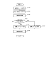
本実施の形態では、制御部106は、漏電を検出する前(ステップST201の動作の前)に既に接続遮断用スイッチ104をオフにしている。従って、制御部106は、漏電を検出する場合において、接続遮断用スイッチ104の開閉を制御しない。
まず、制御部106は、電源側リレー101に対して制御信号Vrypを出力して電源側リレー101をオフにする(ステップST201)。
次に、制御部106は、グランド側リレー102に対して制御信号Vrynを出力してグランド側リレー102をオフにする(ステップST202)。なお、ステップST201の動作とステップST202の動作との順番は、逆でもよい。
次に、電源発生部161は漏電を検出するための電力の供給を開始し、漏電検出部163は漏電の検出を開始する(ステップST203)。
次に、漏電検出部163は、電圧を検出したか否かを判定する(ステップST204)。
漏電検出部163は、電圧を検出していないと判定した場合(ステップST204:NO)には、漏電していないと判断する(ステップST205)。
そして、電源発生部161は漏電を検出するための電力の供給を停止し、漏電検出部163は漏電検出を終了する(ステップST206)。
一方、漏電検出部163は、電圧を検出したと判定した場合(ステップST204:YES)には、漏電していると判断する(ステップST207)。
そして、電源発生部161は漏電を検出するための電力の供給を停止し、漏電検出部163は漏電検出を終了する(ステップST206)。なお、漏電を検出した場合には、ユーザは、漏電している箇所を特定して修理する等の作業を行う。
因みに、漏電検出時において接続遮断用スイッチ104をオンにした場合には、電源発生部161、入出力部162、ケーブル170、充電プラグ180、電源接続部151、抵抗105、溶着検出用スイッチ103、接続遮断用スイッチ104、電源接続部151、充電プラグ180、ケーブル170、入出力部162、及び漏電検出部163の順番で電流が流れる。この結果、漏電検出部163は、上記の電流の流れで生じた電圧を検出し、漏電していない場合であっても、漏電していると誤検出する。従って、本実施の形態では、リレーの溶着検出時以外の時には接続遮断用スイッチ104をオフにして、漏電の誤検出を防いでいる。
<リレー溶着検出装置のリレー溶着検出時の動作>
本発明の実施の形態1に係るリレー溶着検出装置100のリレー溶着検出時の動作について、図3を用いて説明する。
本発明の実施の形態1に係るリレー溶着検出装置100のリレー溶着検出時の動作について、図3を用いて説明する。
リレー溶着検出装置100は、リレー溶着検出時には、充電を停止している。
まず、制御部106は、電源側リレー101に対して制御信号Vrypを出力して電源側リレー101をオフにする(ステップST301)。
次に、制御部106は、グランド側リレー102に対して制御信号Vrynを出力してグランド側リレー102をオフにする(ステップST302)。なお、ステップST301の動作とステップST302の動作との順番は、逆でもよい。
制御部106は、発光ダイオード104Aに接続している制御端子Vc2より制御信号を出力して接続遮断用スイッチ104をオンにする(ステップST303)。これにより、リレー溶着検出装置100は、リレーの溶着を検出することができる。
制御部106は、溶着検出用スイッチ103と接続している電圧検出端子Vdeで検出した電圧が所定値以上低下したか否かを判定する(ステップST304)。例えば、制御部106は、電圧検出端子Vdeで検出した電圧が”H”レベルから”L”レベルに変化したか否かを判定する。
制御部106は、電圧検出端子Vdeで検出した電圧が所定値以上低下したと判定した場合(ステップST304:YES)には、電源側リレー101及びグランド側リレー102が溶着していると判断し(ステップST305)、後述するステップST314まで処理をスキップする。
一方、制御部106は、電圧検出端子Vdeで検出した電圧が所定値以上低下していないと判定した場合(ステップST304:NO)には、電源側リレー101に対して制御信号Vrypを出力して電源側リレー101をオンにする(ステップST306)。
次に、制御部106は、電圧検出端子Vdeで検出した電圧が所定値以上低下したか否かを判定する(ステップST307)。
制御部106は、電圧検出端子Vdeで検出した電圧が所定値以上低下したと判定した場合(ステップST307:YES)には、グランド側リレー102のみが溶着していると判断し(ステップST308)、後述するステップST314まで処理をスキップする。
一方、制御部106は、電圧検出端子Vdeが所定値以上低下していないと判定した場合(ステップST307:NO)には、電源側リレー101に対して制御信号Vrypを出力して電源側リレー101をオフにする(ステップST309)。
次に、制御部106は、グランド側リレー102に対して制御信号Vrynを出力してグランド側リレー102をオンにする(ステップST310)。
次に、制御部106は、電圧検出端子Vdeで検出した電圧が所定値以上低下したか否かを判定する(ステップST311)。
制御部106は、電圧検出端子Vdeで検出した電圧が所定値以上低下したと判定した場合(ステップST311:YES)には、電源側リレー101のみが溶着していると判断し(ステップST312)、後述するステップST314まで処理をスキップする。
一方、制御部106は、電圧検出端子Vdeで検出した電圧が所定値以上低下していないと判定した場合(ステップST311:NO)には、異常なしと判断する(ステップST313)。
次に、制御部106は、電源側リレー101に対して制御信号Vrypを出力して電源側リレー101をオフにするとともに、グランド側リレー102に対して制御信号Vrynを出力してグランド側リレー102をオフにする(ステップST314)。
次に、制御部106は、制御端子Vc2より制御信号を出力して接続遮断用スイッチ104をオフにする(ステップST315)。これにより、漏電検出部163は、漏電検出の際に、誤検出を防ぐことができる。
<実施の形態1の効果>
本実施の形態では、リレーの溶着検出時以外において、接続遮断用スイッチ104をオフにして溶着検出用スイッチ103と外部電源との接続を切断する。これにより、電源側リレー101またはグランド側リレー102の溶着と漏電との両方を検出可能な場合において、漏電の誤検出を防ぐことができる。
本実施の形態では、リレーの溶着検出時以外において、接続遮断用スイッチ104をオフにして溶着検出用スイッチ103と外部電源との接続を切断する。これにより、電源側リレー101またはグランド側リレー102の溶着と漏電との両方を検出可能な場合において、漏電の誤検出を防ぐことができる。
また、本実施の形態によれば、漏電を検出した際に充電を停止するシステムの場合に、漏電していないため安全に充電できるにも関わらず、漏電していると誤検出して充電できなくなることを防ぐことができる。
また、本実施の形態によれば、溶着検出用スイッチをフォトカプラにしたので、低電圧側の制御部を高電圧側の外部電源から絶縁することができる。この結果、本実施の形態では、例えば、外部電源装置160として400Vの充電電圧で充電を行う急速充電器を用いた場合に、制御部106を従来と同じ12Vで動作させることができる。
(実施の形態2)
本発明の実施の形態2における充電システムの構成は図1と同一構成であるので、その説明を省略する。なお、本実施の形態においては、図1に示すリレー溶着検出装置100の符号を用いて説明する。
本発明の実施の形態2における充電システムの構成は図1と同一構成であるので、その説明を省略する。なお、本実施の形態においては、図1に示すリレー溶着検出装置100の符号を用いて説明する。
本実施の形態では、漏電検出時に、接続遮断用スイッチ104をオフにして溶着検出用スイッチ103と外部電源装置160との接続を切断する。これにより、本実施の形態では、電源側リレー101及びグランド側リレー102をオフにしている場合において、溶着検出用スイッチ103を経由して漏電検出部163に電流が流れ込まないようにしている。
<リレー溶着検出装置の漏電検出時の動作>
本発明の実施の形態2に係るリレー溶着検出装置100の漏電検出時の動作について、図4を用いて説明する。
本発明の実施の形態2に係るリレー溶着検出装置100の漏電検出時の動作について、図4を用いて説明する。
まず、制御部106は、発光ダイオード104Aに接続している制御端子Vc2より制御信号を出力して接続遮断用スイッチ104をオフにする(ステップST401)。これにより、漏電検出部163は、漏電を検出する際における誤検出を防ぐことができる。
制御部106は、電源側リレー101をオフにする(ステップST402)。
次に、制御部106は、グランド側リレー102をオフにする(ステップST403)。なお、ステップST402の動作とステップST403の動作との順番は、逆でもよい。
電源発生部161は漏電を検出するための電力の供給を開始し、漏電検出部163は漏電の検出を開始する(ステップST404)。
次に、漏電検出部163は、電圧を検出したか否かを判定する(ステップST405)。
漏電検出部163は、電圧を検出していないと判定した場合(ステップST405:NO)には、漏電していないと判断する(ステップST406)。
そして、電源発生部161は漏電を検出するための電力の供給を停止し、漏電検出部163は漏電検出を終了する(ステップST408)。
一方、漏電検出部163は、電圧を検出したと判定した場合(ステップST405:YES)には、漏電していると判断する(ステップST407)。
そして、電源発生部161は漏電を検出するための電力の供給を停止し、漏電検出部163は漏電検出を終了する(ステップST408)。なお、漏電を検出した場合には、ユーザは、漏電している箇所を特定して修理する等の作業を行う。
最後に、制御部106は、制御端子Vc2より制御信号を出力して接続遮断用スイッチ104をオンにする(ステップST409)。これにより、リレー溶着検出装置100は、リレーの溶着を検出することができる。
なお、漏電検出時において接続遮断用スイッチ104をオンにした場合に漏電していると誤検出する理由は、上記実施の形態1と同一であるのでその説明を省略する。本実施の形態では、漏電検出時には接続遮断用スイッチ104をオフにして、漏電の誤検出を防いでいる。
<リレー溶着検出装置のリレー溶着検出時の動作>
本発明の実施の形態2に係るリレー溶着検出装置100のリレー溶着検出時の動作について、図5を用いて説明する。
本発明の実施の形態2に係るリレー溶着検出装置100のリレー溶着検出時の動作について、図5を用いて説明する。
本実施の形態では、制御部106は、漏電を検出する場合または充電中の場合において接続遮断用スイッチ104をオフにし、漏電を検出する場合と充電中の場合とを除いて接続遮断用スイッチ104をオンにする。従って、制御部106は、リレー溶着検出時には接続遮断用スイッチ104の開閉を制御しない。また、リレー溶着検出装置100は、リレー溶着検出時には、充電を停止している。なお、充電中の場合において接続遮断用スイッチ104をオフにする理由は、充電のロスを防止するためであり、漏電の誤検出を防ぐためではない。
まず、制御部106は、電源側リレー101をオフにする(ステップST501)。
次に、制御部106は、グランド側リレー102をオフにする(ステップST502)。なお、ステップST501の動作とステップST502の動作との順番は、逆でもよい。
制御部106は、溶着検出用スイッチ103に接続している電圧検出端子Vdeで検出した電圧が所定値以上低下したか否かを判定する(ステップST503)。
制御部106は、電圧検出端子Vdeで検出した電圧が所定値以上低下したと判定した場合(ステップST503:YES)には、電源側リレー101及びグランド側リレー102が溶着していると判断し(ステップST504)、後述するステップST513まで処理をスキップする。
一方、制御部106は、電圧検出端子Vdeで検出した電圧が所定値以上低下していないと判定した場合(ステップST503:NO)には、電源側リレー101をオンにする(ステップST505)。
次に、制御部106は、電圧検出端子Vdeで検出した電圧が所定値以上低下したか否かを判定する(ステップST506)。
制御部106は、電圧検出端子Vdeで検出した電圧が所定値以上低下したと判定した場合(ステップST506:YES)には、グランド側リレー102のみが溶着していると判断し(ステップST507)、後述するステップST513まで処理をスキップする。
一方、制御部106は、電圧検出端子Vdeで検出した電圧が所定値以上低下していないと判定した場合(ステップST506:NO)には、電源側リレー101をオフにする(ステップST508)。
次に、制御部106は、グランド側リレー102をオンにする(ステップST509)。
次に、制御部106は、電圧検出端子Vdeで検出した電圧が所定値以上低下したか否かを判定する(ステップST510)。
制御部106は、電圧検出端子Vdeで検出した電圧が所定値以上低下しと判定した場合(ステップST510:YES)には、電源側リレー101のみが溶着していると判断し(ステップST511)、後述するステップST513まで処理をスキップする。
一方、制御部106は、電圧検出端子Vdeで検出した電圧が所定値以上低下していないと判定した場合(ステップST510:NO)には、異常なしと判断する(ステップST512)。
次に、制御部106は、電源側リレー101及びグランド側リレー102をオフにする(ステップST513)。
<実施の形態2の効果>
本実施の形態では、漏電を検出する場合において、接続遮断用スイッチ104をオフにして溶着検出用スイッチ103と外部電源との接続を切断する。これにより、電源側リレー101またはグランド側リレー102の溶着と漏電との両方を検出可能な場合において、漏電の誤検出を防ぐことができる。
本実施の形態では、漏電を検出する場合において、接続遮断用スイッチ104をオフにして溶着検出用スイッチ103と外部電源との接続を切断する。これにより、電源側リレー101またはグランド側リレー102の溶着と漏電との両方を検出可能な場合において、漏電の誤検出を防ぐことができる。
また、本実施の形態によれば、漏電を検出した際に充電を停止するシステムの場合に、漏電していないため安全に充電できるにも関わらず、漏電していると誤検出して充電できなくなることを防ぐことができる。
また、本実施の形態によれば、溶着検出用スイッチをフォトカプラにしたので、低電圧側の制御部を高電圧側の外部電源から絶縁することができる。この結果、本実施の形態では、例えば、外部電源装置160として400Vの充電電圧で充電を行う急速充電器を用いた場合に、制御部106を従来と同じ12Vで動作させることができる。
<全ての実施の形態に共通の変形例>
上記実施の形態1及び実施の形態2において、溶着検出用スイッチ及び接続遮断用スイッチとしてフォトカプラを用いたが、フォトカプラ以外のスイッチを用いてもよい。
上記実施の形態1及び実施の形態2において、溶着検出用スイッチ及び接続遮断用スイッチとしてフォトカプラを用いたが、フォトカプラ以外のスイッチを用いてもよい。
また、上記実施の形態1及び実施の形態2において、リレー溶着検出装置を車輌に搭載したが、車輌以外の蓄電池を有する装置に搭載してもよい。
また、上記実施の形態1及び実施の形態2において、接続遮断用スイッチ104を制御部106の制御によりオフにしたが、手動でオフにしてもよく、少なくとも漏電を検出する場合にオフにすることができれば任意の方法で接続遮断用スイッチ104をオフにすることができる。
2012年9月13日出願の特願2012-201415の日本出願に含まれる明細書、図面及び要約書の開示内容は、すべて本願に援用される。
本発明に係るリレー溶着検出装置は、外部電源から蓄電池への充電経路に設けられたリレーの溶着を検出するのに好適である。
10 充電システム
100 リレー溶着検出装置
101 電源側リレー
102 グランド側リレー
103 溶着検出用スイッチ
103A、104A 発光ダイオード
103B、104B フォトトランジスタ
104 接続遮断用スイッチ
105 抵抗
106 制御部
150 車輌
151 電源接続部
151a 電源側端子
151b グランド側端子
152 蓄電池
160 外部電源装置
161 電源発生部
162 入出力部
163 漏電検出部
170 ケーブル
180 充電プラグ
Vc2 制御端子
Vde 電圧検出端子
100 リレー溶着検出装置
101 電源側リレー
102 グランド側リレー
103 溶着検出用スイッチ
103A、104A 発光ダイオード
103B、104B フォトトランジスタ
104 接続遮断用スイッチ
105 抵抗
106 制御部
150 車輌
151 電源接続部
151a 電源側端子
151b グランド側端子
152 蓄電池
160 外部電源装置
161 電源発生部
162 入出力部
163 漏電検出部
170 ケーブル
180 充電プラグ
Vc2 制御端子
Vde 電圧検出端子
Claims (5)
- 外部電源から蓄電池への充電経路に設けられたリレーの溶着を検出するリレー溶着検出装置であって、
充電停止中に前記リレーをオフした際における前記充電経路の前記リレーよりも前記外部電源側において流れる電流に基づいて、前記リレーの溶着を検出する検出部と、
前記外部電源と前記検出部との接続を開閉するスイッチと、
を有するリレー溶着検出装置。 - 前記スイッチは、
少なくとも漏電を検出する場合に前記外部電源と前記検出部との接続を開放する、
請求項1記載のリレー溶着検出装置。 - 前記スイッチは、
前記リレーの溶着を検出しない場合に前記外部電源と前記検出部との接続を開放する、
請求項2記載のリレー溶着検出装置。 - 前記スイッチは、
第1のフォトカプラであり、
前記検出部は、
前記リレーの前記外部電源側の電圧が所定値以上の際にオンする第2のフォトカプラと、
前記第1のフォトカプラの開閉を制御するとともに、前記第2のフォトカプラのオンとオフとで異なる電圧の検出結果に基づいて前記リレーの溶着を検出し、前記第1のフォトカプラ及び前記第2のフォトカプラにより前記外部電源から電気的に絶縁される制御部と、を有する、
請求項1記載のリレー溶着検出装置。 - 請求項1記載のリレー溶着検出装置を有する車輌。
Priority Applications (5)
| Application Number | Priority Date | Filing Date | Title |
|---|---|---|---|
| EP13837841.9A EP2897242B1 (en) | 2012-09-13 | 2013-09-11 | Device for detecting welding of relay |
| CN201380046753.XA CN104604067B (zh) | 2012-09-13 | 2013-09-11 | 继电器粘连检测装置 |
| US14/427,153 US9989573B2 (en) | 2012-09-13 | 2013-09-11 | Device for detecting welding of relay |
| US15/973,734 US10114059B2 (en) | 2012-09-13 | 2018-05-08 | Device for detecting welding of relay |
| US16/145,379 US10882402B2 (en) | 2012-09-13 | 2018-09-28 | Device for detecting welding of relay |
Applications Claiming Priority (2)
| Application Number | Priority Date | Filing Date | Title |
|---|---|---|---|
| JP2012-201415 | 2012-09-13 | ||
| JP2012201415A JP6308486B2 (ja) | 2012-09-13 | 2012-09-13 | リレー溶着検出装置 |
Related Child Applications (2)
| Application Number | Title | Priority Date | Filing Date |
|---|---|---|---|
| US14/427,153 A-371-Of-International US9989573B2 (en) | 2012-09-13 | 2013-09-11 | Device for detecting welding of relay |
| US15/973,734 Continuation US10114059B2 (en) | 2012-09-13 | 2018-05-08 | Device for detecting welding of relay |
Publications (1)
| Publication Number | Publication Date |
|---|---|
| WO2014041796A1 true WO2014041796A1 (ja) | 2014-03-20 |
Family
ID=50277938
Family Applications (1)
| Application Number | Title | Priority Date | Filing Date |
|---|---|---|---|
| PCT/JP2013/005360 Ceased WO2014041796A1 (ja) | 2012-09-13 | 2013-09-11 | リレー溶着検出装置 |
Country Status (5)
| Country | Link |
|---|---|
| US (3) | US9989573B2 (ja) |
| EP (1) | EP2897242B1 (ja) |
| JP (2) | JP6308486B2 (ja) |
| CN (2) | CN104604067B (ja) |
| WO (1) | WO2014041796A1 (ja) |
Cited By (6)
| Publication number | Priority date | Publication date | Assignee | Title |
|---|---|---|---|---|
| CN104090229A (zh) * | 2014-06-11 | 2014-10-08 | 惠州市亿能电子有限公司 | 多路高压继电器输出粘连的检测电路及其检测方法 |
| US20150070019A1 (en) * | 2013-09-11 | 2015-03-12 | Seiko Epson Corporation | Control apparatus |
| JP2016152680A (ja) * | 2015-02-17 | 2016-08-22 | トヨタ自動車株式会社 | 給電装置及びそれを備えた車両 |
| CN107359598A (zh) * | 2017-08-30 | 2017-11-17 | 潍柴动力股份有限公司 | 一种进气加热继电器故障诊断及保护电路、方法及系统 |
| CN114184936A (zh) * | 2021-11-30 | 2022-03-15 | 上海儒竞智控技术有限公司 | 芯片连焊自检测方法、系统、介质及芯片 |
| US12348064B2 (en) | 2020-09-28 | 2025-07-01 | Honda Motor Co., Ltd | Control device for mobile body, control method therefor, and mobile body including determining a failure of a switching unit when no electrical load is connected |
Families Citing this family (39)
| Publication number | Priority date | Publication date | Assignee | Title |
|---|---|---|---|---|
| EP3034351B1 (en) * | 2014-12-01 | 2024-04-24 | Marelli Europe S.p.A. | Electronic device for controlling the electric charge of a load electrically supplied by a battery pack and system for moving an electric or hybrid traction vehicle using the device |
| DE102015004119A1 (de) * | 2015-03-31 | 2016-10-06 | Audi Ag | Kraftfahrzeug mit einem elektrischen Energiespeicher und zwei Ladeschnittstellen, Ladesystem sowie Verfahren |
| CN104986049B (zh) * | 2015-06-19 | 2017-11-03 | 安徽江淮汽车集团股份有限公司 | 一种接触器控制方法 |
| JP6598604B2 (ja) * | 2015-09-08 | 2019-10-30 | キヤノン株式会社 | 画像形成装置 |
| DE102015219145A1 (de) * | 2015-10-02 | 2017-04-06 | BSH Hausgeräte GmbH | Haushaltsgerät |
| CN105527567A (zh) * | 2016-01-27 | 2016-04-27 | 惠州市蓝微新源技术有限公司 | 电池管理系统的高压继电器粘连检测电路及检测方法 |
| KR102059076B1 (ko) * | 2016-02-19 | 2020-02-11 | 주식회사 엘지화학 | 스위치 부품의 고장 진단 장치 및 방법 |
| CN105946584B (zh) * | 2016-05-17 | 2019-03-15 | 福建万众百源实业有限公司 | 一种汽车电池继电器粘连检测保护装置 |
| CN106183823A (zh) * | 2016-07-08 | 2016-12-07 | 北汽福田汽车股份有限公司 | 车辆、高压控制系统及其控制方法 |
| CN106124980B (zh) * | 2016-08-09 | 2018-11-16 | 潍柴动力股份有限公司 | 一种电动汽车的动力电池主回路继电器故障检测电路及其检测方法 |
| CN106226694B (zh) * | 2016-08-30 | 2019-03-08 | 潍柴动力股份有限公司 | 一种进气加热继电器故障诊断电路、故障诊断方法及系统 |
| KR102194985B1 (ko) * | 2016-09-07 | 2020-12-24 | 삼성에스디아이 주식회사 | 배터리 보호 회로 및 이를 포함하는 배터리 팩 |
| US10017071B2 (en) * | 2016-10-13 | 2018-07-10 | GM Global Technology Operations LLC | Method and system for diagnosing contactor health in a high-voltage electrical system |
| CN106696708A (zh) * | 2016-11-17 | 2017-05-24 | 天津易鼎丰动力科技有限公司 | 电动汽车中判断电池高压回路中的接触器粘连故障的方法 |
| CN106771800A (zh) * | 2016-11-23 | 2017-05-31 | 国家电网公司 | 一种同芯电缆检测装置 |
| CN106740200B (zh) * | 2016-12-19 | 2019-09-06 | 西安特锐德智能充电科技有限公司 | 充电装置、继电器粘连检测方法及电动汽车的充电方法 |
| CN108539831B (zh) * | 2017-03-02 | 2024-06-25 | 深圳市昭恒新能源技术有限公司 | 一种充电设备及其输出端的短路检测电路 |
| CN114325412B (zh) * | 2017-03-20 | 2024-12-06 | 深圳引望智能技术有限公司 | 一种检测电路、方法和装置 |
| KR102371597B1 (ko) * | 2017-04-06 | 2022-03-07 | 현대자동차주식회사 | 차량의 급속충전 제어 장치 및 방법 |
| CN107599848B (zh) * | 2017-10-23 | 2023-11-17 | 宁德时代新能源科技股份有限公司 | 高压检测电路、检测器、电池装置和运载工具 |
| CN108061853A (zh) * | 2017-11-20 | 2018-05-22 | 山东鲁能智能技术有限公司 | 电动汽车直流充电的功率开关触点粘连检测系统及方法 |
| KR102256094B1 (ko) | 2017-11-28 | 2021-05-25 | 주식회사 엘지에너지솔루션 | 배터리 팩 |
| JP6992462B2 (ja) * | 2017-12-08 | 2022-01-13 | トヨタ自動車株式会社 | 外部給電システム及びその漏電検知方法 |
| CN109932641A (zh) * | 2017-12-16 | 2019-06-25 | 郑州宇通客车股份有限公司 | 一种电池系统加热继电器故障诊断方法及装置 |
| CN108254682A (zh) * | 2017-12-28 | 2018-07-06 | 长园深瑞继保自动化有限公司 | 直流充电桩输出接触器粘连故障的判别方法 |
| CN109557403A (zh) * | 2017-12-29 | 2019-04-02 | 蜂巢能源科技有限公司 | 车辆的接触器触点粘连检测装置及方法 |
| CN108832673B (zh) * | 2018-06-06 | 2021-07-23 | 西安特锐德智能充电科技有限公司 | 直流充电系统、pdu及充电通路的启动充电检测方法 |
| CN108982992B (zh) * | 2018-06-06 | 2020-12-08 | 西安特锐德智能充电科技有限公司 | 直流充电系统、pdu及充电通路的在线加入检测方法 |
| JP7159792B2 (ja) * | 2018-10-31 | 2022-10-25 | トヨタ自動車株式会社 | 電動車両 |
| CN109515196B (zh) * | 2018-11-16 | 2021-04-13 | 广州小鹏汽车科技有限公司 | 一种电动汽车控制方法、装置及系统 |
| KR102538989B1 (ko) | 2018-11-22 | 2023-06-01 | 주식회사 엘지에너지솔루션 | Ess에 구비되는 콘텍터의 융착 여부 확인 장치 및 방법 |
| CN109521359B (zh) * | 2018-12-28 | 2020-11-03 | 华人运通(江苏)动力电池系统有限公司 | 一种动力电池负极继电器状态检测电路及方法 |
| CN109596940A (zh) * | 2018-12-29 | 2019-04-09 | 蜂巢能源科技有限公司 | 动力电池充电接触器触点粘连的检测装置、车辆 |
| CN109849733B (zh) * | 2019-02-19 | 2021-02-19 | 广州小鹏汽车科技有限公司 | 用于电动车辆高压继电器粘连检测及处理的装置和方法 |
| CN110148544B (zh) * | 2019-05-05 | 2021-06-04 | 北京新能源汽车股份有限公司 | 防止继电器粘连的方法及装置 |
| CN114223120B (zh) * | 2019-09-18 | 2025-04-15 | 日立安斯泰莫株式会社 | 电子控制装置 |
| CN112505534A (zh) * | 2020-09-29 | 2021-03-16 | 上海亮一科技有限公司 | 一种继电器粘连及输出短路检测电路 |
| KR20230036799A (ko) * | 2021-09-08 | 2023-03-15 | 주식회사 엘지에너지솔루션 | 융접합 보호 모듈 및 이를 포함하는 배터리 시스템 |
| JP7652101B2 (ja) * | 2022-02-08 | 2025-03-27 | トヨタ自動車株式会社 | 充放電装置、車両、および、充放電装置の制御方法 |
Citations (3)
| Publication number | Priority date | Publication date | Assignee | Title |
|---|---|---|---|---|
| JP2009100568A (ja) | 2007-10-17 | 2009-05-07 | Toyota Motor Corp | 電動車両および電動車両の制御方法 |
| JP2010239845A (ja) | 2009-03-31 | 2010-10-21 | Tokyo Electric Power Co Inc:The | 充電システム、電動車両の充電方法、および電動車両 |
| JP5011443B1 (ja) * | 2011-03-30 | 2012-08-29 | パナソニック株式会社 | リレー溶着検出回路及び電力供給システム |
Family Cites Families (22)
| Publication number | Priority date | Publication date | Assignee | Title |
|---|---|---|---|---|
| GB9822515D0 (en) * | 1998-10-16 | 1998-12-09 | Alstom Uk Ltd | Improvements relating to monitoring apparatus for electrical circuits |
| JP2000173428A (ja) * | 1998-12-01 | 2000-06-23 | Sanyo Electric Co Ltd | 電気自動車のメインリレー溶着検出装置 |
| KR100432285B1 (ko) * | 2000-02-18 | 2004-05-22 | 산요덴키가부시키가이샤 | 전동 차량의 릴레이 용착 검출 장치 |
| DE10146753C1 (de) * | 2001-09-22 | 2003-04-24 | Pilz Gmbh & Co | Sicherheitsschaltvorrichtung zum sicheren Abschalten eines elektrischen Verbrauchers |
| JP3679750B2 (ja) * | 2001-11-30 | 2005-08-03 | 三洋電機株式会社 | 漏電検出回路を備える電動車両の電源装置 |
| FR2833747B1 (fr) * | 2001-12-17 | 2005-04-15 | Schneider Electric Ind Sa | Declencheur differentiel comportant un circuit test |
| DE102004020997A1 (de) * | 2004-04-19 | 2005-11-03 | Pilz Gmbh & Co. Kg | Sicherheitsschalteinrichtung für eine Sicherheitsschaltung |
| US8069831B2 (en) * | 2004-11-26 | 2011-12-06 | Fujitsu Ten Limited | Method and apparatus for start control of a vehicle |
| JP2007026741A (ja) * | 2005-07-13 | 2007-02-01 | Jtekt Corp | リレー接点の溶着検出装置 |
| JP4749190B2 (ja) * | 2006-03-24 | 2011-08-17 | 三洋電機株式会社 | 車両用の電源装置とこの電源装置のコンタクターの溶着を判別する溶着検出方法 |
| JP4894646B2 (ja) * | 2007-06-15 | 2012-03-14 | トヨタ自動車株式会社 | 充電装置および充電システム |
| CN201075720Y (zh) * | 2007-09-22 | 2008-06-18 | 天津市松正电动科技有限公司 | 电动车控制器控制电路 |
| JP4873260B2 (ja) * | 2007-12-25 | 2012-02-08 | トヨタ自動車株式会社 | 燃料電池システム |
| JP5240462B2 (ja) | 2009-01-28 | 2013-07-17 | 三菱自動車工業株式会社 | 電気自動車の充電リレー溶着判定装置 |
| JP5421000B2 (ja) * | 2009-07-03 | 2014-02-19 | トヨタ自動車株式会社 | 電動車両、溶着判定装置、および溶着判定プログラム |
| JP5205356B2 (ja) * | 2009-10-09 | 2013-06-05 | 日立オートモティブシステムズ株式会社 | 電源装置とコンタクタ溶着判定方法 |
| JP5087064B2 (ja) * | 2009-11-20 | 2012-11-28 | パナソニック株式会社 | 給電制御装置 |
| JP2011109877A (ja) * | 2009-11-20 | 2011-06-02 | Panasonic Electric Works Co Ltd | 給電制御装置 |
| JP2011210546A (ja) * | 2010-03-30 | 2011-10-20 | Yamatake Corp | リレーの寿命予測装置 |
| WO2012004848A1 (ja) * | 2010-07-05 | 2012-01-12 | トヨタ自動車株式会社 | 充電制御装置 |
| JP5600614B2 (ja) * | 2011-01-31 | 2014-10-01 | パナソニック株式会社 | 給電制御装置 |
| CN202259040U (zh) * | 2011-09-08 | 2012-05-30 | 艾欧史密斯(中国)热水器有限公司 | 一种继电器防粘连装置 |
-
2012
- 2012-09-13 JP JP2012201415A patent/JP6308486B2/ja active Active
-
2013
- 2013-09-11 US US14/427,153 patent/US9989573B2/en active Active
- 2013-09-11 EP EP13837841.9A patent/EP2897242B1/en active Active
- 2013-09-11 WO PCT/JP2013/005360 patent/WO2014041796A1/ja not_active Ceased
- 2013-09-11 CN CN201380046753.XA patent/CN104604067B/zh active Active
- 2013-09-11 CN CN201711333760.4A patent/CN107887883B/zh active Active
-
2018
- 2018-03-02 JP JP2018037490A patent/JP6534020B2/ja active Active
- 2018-05-08 US US15/973,734 patent/US10114059B2/en active Active
- 2018-09-28 US US16/145,379 patent/US10882402B2/en active Active
Patent Citations (3)
| Publication number | Priority date | Publication date | Assignee | Title |
|---|---|---|---|---|
| JP2009100568A (ja) | 2007-10-17 | 2009-05-07 | Toyota Motor Corp | 電動車両および電動車両の制御方法 |
| JP2010239845A (ja) | 2009-03-31 | 2010-10-21 | Tokyo Electric Power Co Inc:The | 充電システム、電動車両の充電方法、および電動車両 |
| JP5011443B1 (ja) * | 2011-03-30 | 2012-08-29 | パナソニック株式会社 | リレー溶着検出回路及び電力供給システム |
Non-Patent Citations (1)
| Title |
|---|
| See also references of EP2897242A4 |
Cited By (9)
| Publication number | Priority date | Publication date | Assignee | Title |
|---|---|---|---|---|
| US20150070019A1 (en) * | 2013-09-11 | 2015-03-12 | Seiko Epson Corporation | Control apparatus |
| CN104090229A (zh) * | 2014-06-11 | 2014-10-08 | 惠州市亿能电子有限公司 | 多路高压继电器输出粘连的检测电路及其检测方法 |
| JP2016152680A (ja) * | 2015-02-17 | 2016-08-22 | トヨタ自動車株式会社 | 給電装置及びそれを備えた車両 |
| EP3059112A1 (en) * | 2015-02-17 | 2016-08-24 | Toyota Jidosha Kabushiki Kaisha | Power supply apparatus with relay contact welding detection and vehicle including the same |
| CN105896519A (zh) * | 2015-02-17 | 2016-08-24 | 丰田自动车株式会社 | 供电装置和具备该供电装置的车辆 |
| US9896047B2 (en) | 2015-02-17 | 2018-02-20 | Toyota Jidosha Kabushiki Kaisha | Power supply apparatus and vehicle including the same |
| CN107359598A (zh) * | 2017-08-30 | 2017-11-17 | 潍柴动力股份有限公司 | 一种进气加热继电器故障诊断及保护电路、方法及系统 |
| US12348064B2 (en) | 2020-09-28 | 2025-07-01 | Honda Motor Co., Ltd | Control device for mobile body, control method therefor, and mobile body including determining a failure of a switching unit when no electrical load is connected |
| CN114184936A (zh) * | 2021-11-30 | 2022-03-15 | 上海儒竞智控技术有限公司 | 芯片连焊自检测方法、系统、介质及芯片 |
Also Published As
| Publication number | Publication date |
|---|---|
| US10114059B2 (en) | 2018-10-30 |
| EP2897242A4 (en) | 2016-05-04 |
| JP2018108023A (ja) | 2018-07-05 |
| US9989573B2 (en) | 2018-06-05 |
| JP6534020B2 (ja) | 2019-06-26 |
| US20180259564A1 (en) | 2018-09-13 |
| JP6308486B2 (ja) | 2018-04-11 |
| US20150241500A1 (en) | 2015-08-27 |
| US20190025362A1 (en) | 2019-01-24 |
| CN107887883B (zh) | 2019-07-19 |
| US10882402B2 (en) | 2021-01-05 |
| JP2014057454A (ja) | 2014-03-27 |
| EP2897242A1 (en) | 2015-07-22 |
| CN107887883A (zh) | 2018-04-06 |
| CN104604067A (zh) | 2015-05-06 |
| EP2897242B1 (en) | 2021-07-07 |
| CN104604067B (zh) | 2018-01-16 |
Similar Documents
| Publication | Publication Date | Title |
|---|---|---|
| JP6308486B2 (ja) | リレー溶着検出装置 | |
| JP6399442B2 (ja) | 給電制御装置 | |
| JP4743346B2 (ja) | 車両の異常検出装置および車両 | |
| US20150054516A1 (en) | Relay weld diagnostic device | |
| US9001483B2 (en) | Relay-welding detection circuit and power supplying system | |
| KR20180113338A (ko) | 차량의 급속충전 제어 장치 및 방법 | |
| JP2014082875A (ja) | 車両の電源装置 | |
| JP2010239773A (ja) | 充電器、電動車両、および、充電システムにおける地絡・短絡の検知方法 | |
| JP5727102B2 (ja) | 充電装置、および、停電時充電復帰方法 | |
| JP5104520B2 (ja) | 電動車両の充電装置 | |
| JP5894427B2 (ja) | 給電制御装置 | |
| WO2014034153A1 (ja) | 漏電検出回路、電池用回路基板、及び電池電源装置 | |
| KR101769645B1 (ko) | 전기 충전 장치 | |
| KR101725498B1 (ko) | 배터리 관리 시스템의 누설 진단 장치 및 방법 | |
| KR20210002971A (ko) | 전기차 충전기용 접지오류 검출장치 및 방법 | |
| KR20220124321A (ko) | 전기차 충전기의 접촉저항 측정 장치 | |
| JP6428448B2 (ja) | 絶縁抵抗低下検出装置 | |
| JP6003776B2 (ja) | 電力供給システムおよびそれを備える車両、ならびに電力供給システムの制御方法 | |
| CN109895632A (zh) | 外部馈电系统以及用于外部馈电系统的漏电检测方法 | |
| CN121224444A (zh) | 一种高压电能回路、故障检测方法及车辆 | |
| JP2015119514A (ja) | 蓄電池の充電制御装置 | |
| JP2021145423A (ja) | ブースターコード | |
| JP2006226763A (ja) | 漏電検出装置 |
Legal Events
| Date | Code | Title | Description |
|---|---|---|---|
| 121 | Ep: the epo has been informed by wipo that ep was designated in this application |
Ref document number: 13837841 Country of ref document: EP Kind code of ref document: A1 |
|
| WWE | Wipo information: entry into national phase |
Ref document number: 14427153 Country of ref document: US |
|
| NENP | Non-entry into the national phase |
Ref country code: DE |