WO2014042094A1 - インソール設計システム - Google Patents
インソール設計システム Download PDFInfo
- Publication number
- WO2014042094A1 WO2014042094A1 PCT/JP2013/074092 JP2013074092W WO2014042094A1 WO 2014042094 A1 WO2014042094 A1 WO 2014042094A1 JP 2013074092 W JP2013074092 W JP 2013074092W WO 2014042094 A1 WO2014042094 A1 WO 2014042094A1
- Authority
- WO
- WIPO (PCT)
- Prior art keywords
- arch
- bone
- foot
- insole
- design
- Prior art date
- Legal status (The legal status is an assumption and is not a legal conclusion. Google has not performed a legal analysis and makes no representation as to the accuracy of the status listed.)
- Ceased
Links
Images






Classifications
-
- A—HUMAN NECESSITIES
- A43—FOOTWEAR
- A43D—MACHINES, TOOLS, EQUIPMENT OR METHODS FOR MANUFACTURING OR REPAIRING FOOTWEAR
- A43D1/00—Foot or last measuring devices; Measuring devices for shoe parts
- A43D1/02—Foot-measuring devices
-
- A—HUMAN NECESSITIES
- A43—FOOTWEAR
- A43B—CHARACTERISTIC FEATURES OF FOOTWEAR; PARTS OF FOOTWEAR
- A43B13/00—Soles; Sole-and-heel integral units
- A43B13/38—Built-in insoles joined to uppers during the manufacturing process, e.g. structural insoles; Insoles glued to shoes during the manufacturing process
-
- A—HUMAN NECESSITIES
- A43—FOOTWEAR
- A43B—CHARACTERISTIC FEATURES OF FOOTWEAR; PARTS OF FOOTWEAR
- A43B7/00—Footwear with health or hygienic arrangements
- A43B7/14—Footwear with health or hygienic arrangements with foot-supporting parts
- A43B7/1405—Footwear with health or hygienic arrangements with foot-supporting parts with pads or holes on one or more locations, or having an anatomical or curved form
- A43B7/141—Footwear with health or hygienic arrangements with foot-supporting parts with pads or holes on one or more locations, or having an anatomical or curved form having an anatomical or curved form
-
- A—HUMAN NECESSITIES
- A43—FOOTWEAR
- A43B—CHARACTERISTIC FEATURES OF FOOTWEAR; PARTS OF FOOTWEAR
- A43B7/00—Footwear with health or hygienic arrangements
- A43B7/14—Footwear with health or hygienic arrangements with foot-supporting parts
- A43B7/1405—Footwear with health or hygienic arrangements with foot-supporting parts with pads or holes on one or more locations, or having an anatomical or curved form
- A43B7/1415—Footwear with health or hygienic arrangements with foot-supporting parts with pads or holes on one or more locations, or having an anatomical or curved form characterised by the location under the foot
- A43B7/142—Footwear with health or hygienic arrangements with foot-supporting parts with pads or holes on one or more locations, or having an anatomical or curved form characterised by the location under the foot situated under the medial arch, i.e. under the navicular or cuneiform bones
-
- A—HUMAN NECESSITIES
- A43—FOOTWEAR
- A43B—CHARACTERISTIC FEATURES OF FOOTWEAR; PARTS OF FOOTWEAR
- A43B7/00—Footwear with health or hygienic arrangements
- A43B7/14—Footwear with health or hygienic arrangements with foot-supporting parts
- A43B7/1405—Footwear with health or hygienic arrangements with foot-supporting parts with pads or holes on one or more locations, or having an anatomical or curved form
- A43B7/1415—Footwear with health or hygienic arrangements with foot-supporting parts with pads or holes on one or more locations, or having an anatomical or curved form characterised by the location under the foot
- A43B7/1445—Footwear with health or hygienic arrangements with foot-supporting parts with pads or holes on one or more locations, or having an anatomical or curved form characterised by the location under the foot situated under the midfoot, i.e. the second, third or fourth metatarsal
-
- A—HUMAN NECESSITIES
- A43—FOOTWEAR
- A43B—CHARACTERISTIC FEATURES OF FOOTWEAR; PARTS OF FOOTWEAR
- A43B7/00—Footwear with health or hygienic arrangements
- A43B7/14—Footwear with health or hygienic arrangements with foot-supporting parts
- A43B7/28—Adapting the inner sole or the side of the upper of the shoe to the sole of the foot
-
- A—HUMAN NECESSITIES
- A43—FOOTWEAR
- A43D—MACHINES, TOOLS, EQUIPMENT OR METHODS FOR MANUFACTURING OR REPAIRING FOOTWEAR
- A43D2200/00—Machines or methods characterised by special features
- A43D2200/60—Computer aided manufacture of footwear, e.g. CAD or CAM
Definitions
- the present invention relates to an insole design system, and more particularly to an insole design system for individually designing and manufacturing an insole (insole) to be laid in shoes.
- a custom-made insole is produced in a shape in which irregularities are appropriately added to the shape of the foot obtained by shaping or measuring. If the positions and dimensions of the irregularities to be added to the shape of the foot are determined by the designer's experience and intuition, different insoles will be produced depending on the designer, which is not preferable.
- design parameters In order to obtain a certain quality, it is desirable to be able to determine design parameters according to certain rules. It is also desirable to be able to explain the design parameters in an easy-to-understand manner, such as what effect the insole is designed for and how it is reflected in the design parameters. It is. In addition, when creating an insole to be used for another shoe based on the design data of the insole created in the past, or recreating the insole while observing changes in the shape of the foot and the movement of the foot during walking In some cases, it is desired that the insole production history can be easily utilized.
- the present invention is intended to provide an insole design system in which design parameters can be determined according to certain rules, the design parameters can be explained in an easy-to-understand manner, and the insole manufacturing history can be easily utilized.
- the present invention provides an insole design system configured as follows in order to solve the above problems.
- the insole design system includes (a) a foot dimension input unit that accepts input of an outer dimension of a foot, and (b) a design parameter that is determined based on the position of the bone of the foot with respect to the shape of a specific portion of the surface of the insole. (C) a bone position estimation unit that estimates the position of the bone as a reference for the design parameter from the dimensions received by the foot dimension input unit; and (d) the bone A data calculation unit that calculates data for forming the shape of the surface of the insole from the position of the bone estimated by the position estimation unit and the design parameter received by the design parameter input unit;
- the insole design system calculates data for forming the surface shape of the insole when the dimensions of the outer shape of the foot and the design parameters are input.
- the design parameters are determined based on the position of the foot bone. Therefore, the design parameter of the insole can be determined according to a certain rule considering the position of the foot bone. In addition, the design parameters can be explained in an easy-to-understand manner. Further, by storing design parameters based on the position of the bone of the foot as the insole production history, the insole production history can be easily utilized.
- the specific portion includes an inner arch corresponding to the inner longitudinal arch of the foot.
- the design parameters include a peak height, peak position and arch length of the inner arch.
- the peak position of the inner arch is determined on the basis of any one of the inner wedge bone, the scaphoid bone, and the distance projection of the heel.
- the arch length of the inner arch is determined based on the position of the heel at one end of the inner arch and the position of the first metatarsal bone as the other end of the inner arch.
- the bone position estimation unit is configured to receive the positions of the inner cuneiform bone, the scaphoid bone, the heel and the talus described above, and the first metatarsal bone, the dimensions received by the foot dimension input unit. Estimated from
- the inner arch corresponding to the inner longitudinal arch of the foot can be designed easily and efficiently with reference to the bone whose position is estimated from the dimensions of the outer shape of the foot.
- the specific portion includes an outer arch corresponding to the outer longitudinal arch of the foot.
- the design parameters include peak height, peak position and arch length of the outer arch.
- the peak position of the outer arch is determined based on the position of the cubic bone.
- the arch length of the outer arch is determined based on the position of the heel at one end of the outer arch and the position of the fifth metatarsal as the other end of the outer arch.
- the bone position estimation unit estimates the positions of the cubic bone, the heel, and the fifth metatarsal from the dimensions received by the foot dimension input unit.
- the outer arch corresponding to the outer longitudinal arch of the foot can be designed easily and efficiently with reference to the bone whose position is estimated from the dimensions of the outer shape of the foot.
- design parameters can be determined according to certain rules, and the design parameters can be explained in an easy-to-understand manner.
- FIG. 1 is a schematic view of an insole. It is a block diagram which shows the structure of an insole design system. It is explanatory drawing of the dimension of the external shape of a leg
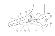
- FIG. 1 is an explanatory diagram of the arch structure of the skeleton of the foot 2 and illustrates the right foot.
- FIG. 2 is a schematic diagram showing the shape of the surface 10 s of the insole 10 and illustrates the left foot.
- the skeleton of the foot 2 has arcs of lines 4, 6, and 8 connecting the three points of the base of the thumb, the base of the little finger, and the heel. They are called the vertical arch 6 and the horizontal arch 8.
- FIG. 3 is a block diagram showing the configuration of the insole design system 50.
- the insole design system 50 is configured on a server, is connected to a terminal 70 via a communication network 80 such as a LAN or the Internet, and communicates with the terminal 70.
- a communication network 80 such as a LAN or the Internet
- the terminal 70 for example, a personal computer provided with a display, a keyboard, a touch pad, a mouse, a tablet computer provided with a touch panel, a smartphone (multifunctional mobile phone / PHS), or the like can be used.
- a part of the functions of the insole design system 50 may be installed in the terminal 70 as application software.
- the insole design system 50 and the terminal 70 may be integrated by direct connection or the like, and configured as a stand-alone dedicated device.
- the insole design system 50 includes a foot dimension input unit 52, a design parameter input unit 54, a bone position estimation unit 56, a data calculation unit 58, and an output unit 60.
- the foot dimension input unit 52 sends data for displaying the screen shown in FIG. 15 on the terminal 70 to the terminal 70.
- the foot dimension input unit 52 receives input regarding the dimensions of the outer shape of the foot.
- the dimensions of the outer shape of the foot that the foot dimension input unit 52 receives input include the dimensions of the foot length A, the foot width B, and the heel width C, as shown in the explanatory view of FIG.
- the foot length A, foot width B, and heel width C may be appropriately defined.
- the foot length A is the length of the foot outline on a line along the line connecting the heel and the second heel when the reference with which the foot contacts is viewed vertically.
- the foot width B is the length of the outer shape of the foot on the line connecting the bases of the first and fifth base when the reference with which the foot contacts is viewed vertically.
- the heel width C is the width of the outer shape of the foot at a position 17% of the foot length from the heel when viewed vertically from the reference with which the foot is in contact (the dimension on the line perpendicular to the line connecting the heel and the second heel). .
- the bone position estimation unit 56 generates a specific bone included in the skeleton 30 inside the foot 2 (details will be described later) from the dimension data of the outer shape of the foot that the foot dimension input unit 52 has received. .) Position.
- the bone position estimation unit 56 estimates the position of the bone using, for example, standard model data in which the outer dimension of the foot and the position of the bone are associated in advance. Specifically, for the foot length, foot width, and heel width, the ratio of the data received by the foot dimension input unit 52 and the data of the standard model is obtained, and the standard model is enlarged / reduced based on this ratio, The position of the standard model bone that has been enlarged or reduced is taken as the estimated position. By preparing several standard models in advance, selecting several standard models with small differences from the input data of foot length, foot width, and heel width, and interpolating using the selected standard models, May be estimated. Different standard models may be used depending on the type of foot (Greek type, Egyptian type, square type, etc.).
- the position of the foot bone may be estimated by a method other than the above, but the position of the foot bone is a reference for designing the insole, and thus needs to be estimated uniquely.
- the design parameter input unit 54 sends data for displaying the screens shown in FIGS. 16 to 20 to the terminal 70 in response to an operation from the terminal 70.
- the design parameter input unit 54 inputs the design parameters. Accept.
- the design parameter input unit 54 receives input of the following design parameters (a) to (g) from the terminal 70.
- basic data of the insole can be input. That is, the insole length L and the insole width W shown in the plan view of FIG. 6 and the insole thickness T shown in the side view of FIG. 7 (dimensions between the bottom surface 12t and the top surface 12s for the base portion 12 having a certain thickness).
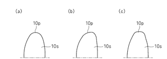
- the type of insole shape for the toe portion shown in the enlarged view of the main part in FIG. 7A is a round
- FIG. 7B is an oblique
- FIG. 7C is a square. 6 to 8
- reference numeral 10p is a toe side end
- reference numeral 10q is a heel side end.
- (B) Peak height, peak position, and arch length of the inner arch By operating the terminal 70 while the screen shown in FIG. 17 is displayed on the terminal 70, the inner arch 10a of the insole 10 (see FIG. 2) Design parameters (peak height, peak position and arch length) can be entered.
- the peak height is the height of the peaks 14s and 14t of the inner arches 14a and 14b, and is a dimension in the vertical direction from the reference surface 12s (the upper surface 12s of the base portion 12).
- the peak positions are the positions of the peaks 14s and 14t of the inner arches 14a and 14b, and any one position of the distance projection 34x of the inner wedge bone 32, the scaphoid bone 33, and the rod 34 is selected, and if necessary. Enter the length in the foot length direction from the selected position to the peak position. That is, the peaks 14s and 14t of the inner arches 14a and 14b are arranged immediately below the selected bone and at positions shifted from there in the foot length direction.
- the positions of the toe side ends 14p and 14q of the inner arches 14a and 14b are input. That is, the position of the head 31a or the front 31b of the first metatarsal 31 is selected, and the dimension in the foot length direction from the selected position to the toe side ends 14p and 14q is input as necessary.
- the heel side ends 14x of the inner arches 14a and 14b are determined based on the position of the ridge 34, and it is not necessary to input design parameters. Both ends 14p, 14q; 14x of the inner arches 14a, 14b are on the reference surface 12s (the upper surface 12s of the base portion 12).
- the peak height is the height of the peaks 15s and 15t of the outer arches 15a and 15b, and is a dimension in the vertical direction from the reference surface 12s (the upper surface 12s of the base portion 12).
- the peak positions are positions of the peaks 15s and 15t of the outer arches 15a and 15b, and a predetermined position (for example, the center position) of the cubic bone 35 is used as a reference, and in the foot length direction from the reference position to the peak position as necessary. Enter the dimensions. That is, the peaks 15s and 15t of the outer arches 15a and 15b are arranged directly below a predetermined position of the cubic bone 35 and at positions shifted from there in the foot length direction.
- the positions of the toe side ends 15p and 15q of the outer arches 15a and 15b are input. That is, the head 36a or the intermediate position 36b of the fifth metatarsal 36 is selected, and the dimensions in the foot length direction from the selected position to the toe side ends 15p and 15q are input as necessary.
- the heel side ends 15x of the outer arches 15a and 15b are determined based on the position of the ridge 34, and it is not necessary to input design parameters. Both ends 15p, 15q; 15x of the outer arches 15a, 15b are on the reference surface 12s (the upper surface 12s of the base portion 12).
- the peak height is the height of the peak 16a of the lateral arch 16 and is the protruding dimension in the vertical direction from the reference surface 12s. is there.
- the peak position is based on the center point O of the foot width B, and if necessary, a dimension for shifting the peak 16a of the lateral arch 16 from the reference position (center point O) in the foot length direction indicated by the arrow 16x is input.
- the peak position of the horizontal arch is fixed in the foot width direction.
- the peak length is determined from the peak height since the cross-sectional shape of the lateral arch is determined in advance.
- the peak position in the foot width direction may be input (movable). Also, the peak length may be input.
- (E) Wedge By operating the terminal 70 in a state where the screen shown in FIG. 19 is displayed on the terminal 70, the main ball 20, the small ball 22, the entire basket 24 shown in FIG. 26, the design parameter is input as the height from the reference surface 12s for the outer side 28. The inclination of the foot can be adjusted by these parameters.
- Shape of heel Design parameters can be input for the shape of the heel portion by operating the terminal 70 in a state where the screen shown in FIG. 20 is displayed on the terminal 70.
- FIGS. 12A and 12B show a cross section of the heel portion 10d of the insole 10 cut along the foot width direction (direction intersecting the foot length direction).
- (G) Arch sectional shape By operating the terminal 70 in a state where the screen shown in FIG. 20 is displayed on the terminal 70, design parameters can be input for the arch sectional shape.
- the arch cross-sectional shape is selected from a V shape shown in FIG. 13A and a round shape shown in FIG.
- FIGS. 13A and 13B show cross sections obtained by cutting an intermediate portion in the foot length direction of the insole 10 along the foot width direction.
- the data calculation unit 58 forms the three-dimensional shape of the surface 10 s of the insole 10 from the bone position estimated by the bone position estimation unit 56 and the design parameters received by the design parameter input unit 54.
- the material of the member that is partially added to form the three-dimensional shape of the surface 10s of the insole 10 in the data calculated by the design parameter calculation unit 58 -Data such as dimensions may be included.
- the output unit 60 outputs the data calculated by the data calculation unit 58 directly to the insole processing device, to the temporary storage device, to the recording medium, or to the design terminal or other terminal. Or
- the shape of the insole can be designed easily and efficiently in consideration of the position of the bone of the foot. Since the design parameters are determined based on the position of the bone, if the design rules are determined, everyone can design in the same manner, and an insole having a certain quality can be designed and manufactured.
- the design parameters are defined based on the bone position, the design parameters can be explained in an easy-to-understand manner.
- an insole production history by storing design parameters based on the position of the bones of the foot, when creating an insole for another shoe based on the design data of an insole produced in the past, The insole production history can be used easily and efficiently when the insole is remade while observing changes in the shape of the foot and the movement of the foot during walking. For example, when an arch structure of a foot is corrected with an insole, it is easy to design and manufacture an insole whose shape is changed according to the progress of correction.
- design parameters can be determined according to certain rules, and the design parameters can be explained in an easy-to-understand manner.
- design parameters and bones that serve as reference for design parameters may be selected as appropriate, and are not limited to the embodiments.
- input of design parameters regarding the position in the foot width direction of the inner arch or the outer arch may be accepted.
- the insole design system of the present invention is not limited to an insole (an insole that is a separate member from the footwear) that is detachably attached to the footwear, but an insole that forms a part of the footwear (the part where the sole touches). Insole) is also applicable.
- the insole design system of the present invention may be configured such that the data calculation unit calculates processing machine control data for cutting out the surface shape of a portion where the soles of footwear such as sandals and clogs contact.
Landscapes
- Health & Medical Sciences (AREA)
- Epidemiology (AREA)
- General Health & Medical Sciences (AREA)
- Public Health (AREA)
- Life Sciences & Earth Sciences (AREA)
- Biophysics (AREA)
- Footwear And Its Accessory, Manufacturing Method And Apparatuses (AREA)
- Engineering & Computer Science (AREA)
- Architecture (AREA)
- Software Systems (AREA)
Description
端末70に図16に示す画面が表示された状態で、端末70を操作することにより、インソールの基本データを入力できる。すなわち、図6の平面図に示すインソール長L及びインソール幅Wと、図7の側面図に示すインソール厚T(一定の厚さを有するベース部12についての底面12tと上面12sとの間の寸法)と、図7の要部拡大図に示す足先部分についてのインソール形状のタイプとを、入力できる。図7(a)はラウンド、図7(b)はオブリーク、図7(c)はスクエアである。図6~図8において、符号10pは足先側端、符号10qは踵側端である。インソールを敷く靴内部の寸法・形状に応じて、インソールの基本データを入力する。
端末70に図17に示す画面が表示された状態で、端末70を操作することにより、インソール10の内側アーチ10a(図2参照)についての設計パラメータ(ピーク高さ、ピーク位置及びアーチ長さ)を入力できる。
端末70に図17に示す画面が表示された状態で、端末70を操作することにより、インソール10の外側アーチ10b(図2参照)についての設計パラメータ(ピーク高さ、ピーク位置及びアーチ長さ)を入力できる。
端末70に図18に示す画面が表示された状態で、端末70を操作することにより、インソール10の横アーチ10c(図2参照)についての設計パラメータ(ピーク高さ及びピーク位置)を入力できる。
端末70に図19に示す画面が表示された状態で、端末70を操作することにより、図14の説明図に示す母趾球20、小趾球22、踵全体24、踵内側26、踵外側28について基準面12sからの高さを、設計パラメータを入力する。これらのパラメータによって、足の傾きを調整することができる。
端末70に図20に示す画面が表示された状態で、端末70を操作することにより、踵部の形状について、設計パラメータを入力できる。
端末70に図20に示す画面が表示された状態で、端末70を操作することにより、アーチ断面形状について、設計パラメータを入力できる。
4 内側縦アーチ
6 外側縦アーチ
8 横アーチ
10 インソール
10a 内側アーチ
10b 外側アーチ
10c 横アーチ
10d 踵部
10p 足先端
10q 踵側端
10s 表面
12 ベース部
12s 上面(基準面)
12t 底面
14a,14b 内側アーチ
14p,14q 足先側端(一方端)
14s,14t ピーク
14x 踵側端(他方端)
15a,15b 外側アーチ
15p,15q 足先側端(一方端)
15s,15t ピーク
15x 踵側端(他方端)
16 横アーチ
16a ピーク
16x 足長方向
20 母趾球
22 小趾球
24 踵全体
26 踵内側
28 踵外側
30 骨格
31 中足骨
31a 骨頭
31b 骨頭手前
32 内側楔状骨
33 舟状骨
34 踵
34x 載距突起
35 立方骨
36 第五中足骨
36a 骨頭
36b 中間位
50 インソール設計システム
52 足寸法入力部
54 設計パラメータ入力部
56 骨位置推定部
58 データ算出部
60 出力部
70 端末
80 通信網
Claims (3)
- 足の外形の寸法の入力を受け付ける足寸法入力部と、
インソールの表面の特定部分の形状について、前記足の骨の位置を基準に決定される設計パラメータの入力を受け付ける設計パラメータ入力部と、
前記設計パラメータの基準となる前記骨の位置を、前記足寸法入力部が受け付けた前記寸法から推定する骨位置推定部と、
前記骨位置推定部が推定した前記骨の位置と、前記設計パラメータ入力部が受け付けた前記設計パラメータとから、前記インソールの前記表面の形状を形成するためのデータを算出するデータ算出部と、
を備えたことを特徴とする、インソール設計システム。 - 前記特定部分は、足の内側縦アーチに対応する内側アーチを含み、
前記設計パラメータは、前記内側アーチのピーク高さ、ピーク位置及びアーチ長さを含み、
前記内側アーチのピーク位置は、内側楔状骨と舟状骨と踵の載距突起とのいずれか一つを基準に決定され、
前記内側アーチのアーチ長さは、前記内側アーチの一方端が前記踵の位置を基準に決定され、前記内側アーチの他方端が第一中足骨の位置を基準に決定され、
前記骨位置推定部は、前記内側楔状骨と、前記舟状骨と、前記踵及びその前記載距突起と、前記第一中足骨との位置を、前記足寸法入力部が受け付けた前記寸法から推定することを特徴とする、請求項1に記載のインソール設計システム。 - 前記特定部分は、足の外側縦アーチに対応する外側アーチを含み、
前記設計パラメータは、前記外側アーチのピーク高さ、ピーク位置及びアーチ長さを含み、
前記外側アーチのピーク位置は、立方骨の位置を基準に決定され、
前記外側アーチのアーチ長さは、前記外側アーチの一方端が前記踵の位置を基準に決定され、前記外側アーチの他方端が第五中足骨の位置を基準に決定され、
前記骨位置推定部は、前記立方骨と前記踵と前記第五中足骨との位置を、前記足寸法入力部が受け付けた前記寸法から推定することを特徴とする、請求項1又は2に記載のインソール設計システム。
Priority Applications (2)
| Application Number | Priority Date | Filing Date | Title |
|---|---|---|---|
| US14/378,239 US10264853B2 (en) | 2012-09-11 | 2013-09-06 | Insole design and fabricate system |
| JP2014535528A JPWO2014042094A1 (ja) | 2012-09-11 | 2013-09-06 | インソール設計システム |
Applications Claiming Priority (2)
| Application Number | Priority Date | Filing Date | Title |
|---|---|---|---|
| JP2012-199557 | 2012-09-11 | ||
| JP2012199557 | 2012-09-11 |
Publications (1)
| Publication Number | Publication Date |
|---|---|
| WO2014042094A1 true WO2014042094A1 (ja) | 2014-03-20 |
Family
ID=50278207
Family Applications (1)
| Application Number | Title | Priority Date | Filing Date |
|---|---|---|---|
| PCT/JP2013/074092 Ceased WO2014042094A1 (ja) | 2012-09-11 | 2013-09-06 | インソール設計システム |
Country Status (3)
| Country | Link |
|---|---|
| US (1) | US10264853B2 (ja) |
| JP (2) | JPWO2014042094A1 (ja) |
| WO (1) | WO2014042094A1 (ja) |
Cited By (5)
| Publication number | Priority date | Publication date | Assignee | Title |
|---|---|---|---|---|
| JP2017522917A (ja) * | 2014-05-09 | 2017-08-17 | アールエスプリント エヌ.ヴィ. | 履物の設計のための方法および装置 |
| WO2019088232A1 (ja) | 2017-11-02 | 2019-05-09 | Jsr株式会社 | 情報処理装置、情報処理システム、インソールの製造システム、インソールの製造方法、情報処理方法及びプログラム |
| US10482214B2 (en) | 2014-05-09 | 2019-11-19 | Rsprint Nv | Methods and apparatuses for designing footwear |
| JP2022089563A (ja) * | 2020-12-04 | 2022-06-16 | ゴールド グラビティー プロプライエタリ リミテッド | インナーソールの製作方法 |
| JP7708468B1 (ja) | 2024-06-19 | 2025-07-15 | 株式会社M.Lab | 足底装着体 |
Families Citing this family (8)
| Publication number | Priority date | Publication date | Assignee | Title |
|---|---|---|---|---|
| JP6551754B2 (ja) * | 2017-05-22 | 2019-07-31 | 株式会社シュアレ | 履物用の中敷体およびそれを備えた履物 |
| CN112822956A (zh) | 2018-10-10 | 2021-05-18 | Jsr株式会社 | 矫形器、矫形器的制造方法、信息处理装置、信息处理方法、系统、以及程序 |
| CN111345544A (zh) * | 2018-12-20 | 2020-06-30 | 澳爵医疗科技(上海)有限公司 | 一种矫形鞋垫及其制备方法 |
| KR102111129B1 (ko) * | 2019-02-27 | 2020-05-14 | 한양여자대학교 산학협력단 | 발 아치부 유형 데이터 획득 시스템 및 이를 이용한 맞춤 인솔 제조방법 |
| JP2021134475A (ja) * | 2020-02-22 | 2021-09-13 | 株式会社ドリーム・ジーピー | 靴下設計システム |
| WO2022080296A1 (ja) * | 2020-10-13 | 2022-04-21 | Jsr株式会社 | 義肢又は装具の製造又は設計の支援システム、義肢又は装具の提供方法、提供プログラム、製造方法、及び端末用プログラム |
| KR102531528B1 (ko) * | 2022-02-07 | 2023-05-10 | 허민수 | 온라인 네트워크를 이용한 맞춤형 인솔의 주문 시스템 |
| JP2024031309A (ja) * | 2022-08-26 | 2024-03-07 | 株式会社アシックス | 中敷設計装置、および中敷設計方法 |
Citations (2)
| Publication number | Priority date | Publication date | Assignee | Title |
|---|---|---|---|---|
| JP2001000208A (ja) * | 1999-06-25 | 2001-01-09 | Yamanaka Sports:Kk | セミオ─ダ─靴製造方法 |
| WO2002040941A1 (en) * | 2000-11-15 | 2002-05-23 | National Institute Of Advanced Industrial Science And Technology | Footprint information distributing system |
Family Cites Families (17)
| Publication number | Priority date | Publication date | Assignee | Title |
|---|---|---|---|---|
| JPH0515205Y2 (ja) | 1989-11-01 | 1993-04-22 | ||
| JP3031739U (ja) | 1996-05-28 | 1996-12-03 | 文敏 甲斐 | 変形性膝矯正具 |
| JPH11187907A (ja) | 1997-12-26 | 1999-07-13 | Reform Shop Akagi:Kk | 足の計測装置、靴の計測装置、足及び靴の計測装置、計測システム、記憶媒体、及び靴 |
| JP3784680B2 (ja) | 2000-09-14 | 2006-06-14 | 茂 竹中 | 履き物用底部・中敷き |
| JP3474534B2 (ja) * | 2000-12-15 | 2003-12-08 | 寿代 石丸 | 靴型設計方法および靴型設計装置 |
| US20020138923A1 (en) | 2001-03-27 | 2002-10-03 | Irshaad Shaffeeullah | Method and apparatus for producing individually contoured shoe insert |
| JP3977771B2 (ja) | 2002-10-08 | 2007-09-19 | 株式会社村井 | 履き物用中敷きおよび履き物 |
| US20060143839A1 (en) * | 2003-02-20 | 2006-07-06 | Thomas Fromme | Method for producing made-to-measure orthopaedic shoes |
| JP2004275611A (ja) | 2003-03-18 | 2004-10-07 | Cozy:Kk | 靴中敷きの製造方法及び受注生産システム |
| JP3921453B2 (ja) | 2003-04-04 | 2007-05-30 | 株式会社アシックス | 足の傾角測定方法、靴または靴用中敷選択方法、靴または靴用中敷製造方法、および、足の傾角測定装置 |
| US7089152B2 (en) | 2003-06-19 | 2006-08-08 | Mizuno Corporation | System and method for assisting shoe selection |
| JP3970822B2 (ja) | 2003-09-19 | 2007-09-05 | 株式会社アシックス | 靴または靴底パーツの適合方法、選定システムおよび選定装置ならびに足型の決定方法 |
| JP2009045244A (ja) | 2007-08-21 | 2009-03-05 | Dream Gp:Kk | 足計測装置 |
| JP3137991U (ja) | 2007-10-04 | 2007-12-13 | 老牛皮國際股▲ふん▼有限公司 | 靴の中敷 |
| US9572402B2 (en) * | 2007-10-23 | 2017-02-21 | Nike, Inc. | Articles and methods of manufacturing articles |
| JP5390834B2 (ja) | 2008-11-12 | 2014-01-15 | ブレース・フィット合同会社 | インソール及びハーフインソール |
| US8904675B2 (en) * | 2011-08-01 | 2014-12-09 | Chanda Koch | Footwear articles and footwear article modification methods |
-
2013
- 2013-09-06 WO PCT/JP2013/074092 patent/WO2014042094A1/ja not_active Ceased
- 2013-09-06 JP JP2014535528A patent/JPWO2014042094A1/ja active Pending
- 2013-09-06 US US14/378,239 patent/US10264853B2/en active Active
-
2016
- 2016-06-10 JP JP2016116679A patent/JP6267745B2/ja active Active
Patent Citations (2)
| Publication number | Priority date | Publication date | Assignee | Title |
|---|---|---|---|---|
| JP2001000208A (ja) * | 1999-06-25 | 2001-01-09 | Yamanaka Sports:Kk | セミオ─ダ─靴製造方法 |
| WO2002040941A1 (en) * | 2000-11-15 | 2002-05-23 | National Institute Of Advanced Industrial Science And Technology | Footprint information distributing system |
Cited By (8)
| Publication number | Priority date | Publication date | Assignee | Title |
|---|---|---|---|---|
| JP2017522917A (ja) * | 2014-05-09 | 2017-08-17 | アールエスプリント エヌ.ヴィ. | 履物の設計のための方法および装置 |
| US10482214B2 (en) | 2014-05-09 | 2019-11-19 | Rsprint Nv | Methods and apparatuses for designing footwear |
| JP2020163154A (ja) * | 2014-05-09 | 2020-10-08 | アールエスプリント エヌ.ヴィ. | 履物の設計のための方法および装置 |
| JP7007419B2 (ja) | 2014-05-09 | 2022-01-24 | アールエスプリント エヌ.ヴィ. | 履物の設計のための方法および装置 |
| WO2019088232A1 (ja) | 2017-11-02 | 2019-05-09 | Jsr株式会社 | 情報処理装置、情報処理システム、インソールの製造システム、インソールの製造方法、情報処理方法及びプログラム |
| JP2022089563A (ja) * | 2020-12-04 | 2022-06-16 | ゴールド グラビティー プロプライエタリ リミテッド | インナーソールの製作方法 |
| JP7708468B1 (ja) | 2024-06-19 | 2025-07-15 | 株式会社M.Lab | 足底装着体 |
| JP2026001658A (ja) * | 2024-06-19 | 2026-01-07 | 株式会社M.Lab | 足底装着体 |
Also Published As
| Publication number | Publication date |
|---|---|
| JP2016155042A (ja) | 2016-09-01 |
| US20150006119A1 (en) | 2015-01-01 |
| JP6267745B2 (ja) | 2018-01-24 |
| US10264853B2 (en) | 2019-04-23 |
| JPWO2014042094A1 (ja) | 2016-08-18 |
Similar Documents
| Publication | Publication Date | Title |
|---|---|---|
| JP6267745B2 (ja) | インソール設計システム | |
| EP2923287B1 (en) | Orthosis | |
| Luximon et al. | Shoe-last design innovation for better shoe fitting | |
| JP5690454B1 (ja) | 靴底 | |
| CA2587090C (en) | Method for design and manufacture of insoles | |
| EP2190315B1 (en) | Three-dimensional design lasts for footwear | |
| JP7506563B2 (ja) | データ生成装置、靴型作製システム、およびデータ生成方法 | |
| EP2908681A1 (en) | Customized shoe textures and shoe portions | |
| US20160331071A1 (en) | Systems and methods for making custom orthotics | |
| Germani et al. | Tools for design and validation of shoe lasts for diabetic patients | |
| CN113204808B (zh) | 一种鞋垫设计方法、装置、计算机设备和存储介质 | |
| KR20090093116A (ko) | 생체역학적 진단 데이터를 이용한 맞춤형 인솔 제작 방법및 상기 방법을 수행하기 위한 시스템 | |
| WO2017057388A1 (ja) | インソール設計システム、靴、靴とインソールの組み合わせ方法 | |
| EP2501251B1 (en) | Functional insole | |
| Ma et al. | Design and manufacture of shoe lasts | |
| CN111222217A (zh) | 鞋垫设计方法及鞋垫设计系统 | |
| KR20220124800A (ko) | 돌출부를 갖는 신발류 및 그 구성 | |
| JP2014111196A (ja) | インソールの製造方法 | |
| Mandolini et al. | Foot plantar pressure offloading: How to select the right material for a custom made insole | |
| JP4913263B2 (ja) | 中敷き及び中敷きの作成方法 | |
| TW202000063A (zh) | 定義鞋墊足弓特徵的方法 | |
| Li et al. | A Feature-based Shoe-last Design and its Automatic Model Construction Method in CAD Systems. | |
| JP2024179135A (ja) | 中敷設計装置、中敷設計方法、およびプログラム | |
| Spahiu et al. | A methodology to use digital tools for design and manufacturing of shoe parts as heels | |
| Spahiu et al. | A methodology to use digital tools for design and manufacturing of footwear parts as heels |
Legal Events
| Date | Code | Title | Description |
|---|---|---|---|
| 121 | Ep: the epo has been informed by wipo that ep was designated in this application |
Ref document number: 13836489 Country of ref document: EP Kind code of ref document: A1 |
|
| ENP | Entry into the national phase |
Ref document number: 2014535528 Country of ref document: JP Kind code of ref document: A |
|
| WWE | Wipo information: entry into national phase |
Ref document number: 14378239 Country of ref document: US |
|
| NENP | Non-entry into the national phase |
Ref country code: DE |
|
| 122 | Ep: pct application non-entry in european phase |
Ref document number: 13836489 Country of ref document: EP Kind code of ref document: A1 |