WO2014045330A1 - 導電性部材、電子写真装置およびプロセスカートリッジ - Google Patents
導電性部材、電子写真装置およびプロセスカートリッジ Download PDFInfo
- Publication number
- WO2014045330A1 WO2014045330A1 PCT/JP2012/006659 JP2012006659W WO2014045330A1 WO 2014045330 A1 WO2014045330 A1 WO 2014045330A1 JP 2012006659 W JP2012006659 W JP 2012006659W WO 2014045330 A1 WO2014045330 A1 WO 2014045330A1
- Authority
- WO
- WIPO (PCT)
- Prior art keywords
- carbon black
- mass
- conductive
- elastic layer
- electrical resistance
- Prior art date
- Legal status (The legal status is an assumption and is not a legal conclusion. Google has not performed a legal analysis and makes no representation as to the accuracy of the status listed.)
- Ceased
Links
Images

Classifications
-
- G—PHYSICS
- G03—PHOTOGRAPHY; CINEMATOGRAPHY; ANALOGOUS TECHNIQUES USING WAVES OTHER THAN OPTICAL WAVES; ELECTROGRAPHY; HOLOGRAPHY
- G03G—ELECTROGRAPHY; ELECTROPHOTOGRAPHY; MAGNETOGRAPHY
- G03G15/00—Apparatus for electrographic processes using a charge pattern
- G03G15/02—Apparatus for electrographic processes using a charge pattern for laying down a uniform charge, e.g. for sensitising; Corona discharge devices
- G03G15/0208—Apparatus for electrographic processes using a charge pattern for laying down a uniform charge, e.g. for sensitising; Corona discharge devices by contact, friction or induction, e.g. liquid charging apparatus
- G03G15/0216—Apparatus for electrographic processes using a charge pattern for laying down a uniform charge, e.g. for sensitising; Corona discharge devices by contact, friction or induction, e.g. liquid charging apparatus by bringing a charging member into contact with the member to be charged, e.g. roller, brush chargers
- G03G15/0233—Structure, details of the charging member, e.g. chemical composition, surface properties
-
- G—PHYSICS
- G03—PHOTOGRAPHY; CINEMATOGRAPHY; ANALOGOUS TECHNIQUES USING WAVES OTHER THAN OPTICAL WAVES; ELECTROGRAPHY; HOLOGRAPHY
- G03G—ELECTROGRAPHY; ELECTROPHOTOGRAPHY; MAGNETOGRAPHY
- G03G15/00—Apparatus for electrographic processes using a charge pattern
- G03G15/06—Apparatus for electrographic processes using a charge pattern for developing
- G03G15/08—Apparatus for electrographic processes using a charge pattern for developing using a solid developer, e.g. powder developer
- G03G15/0806—Apparatus for electrographic processes using a charge pattern for developing using a solid developer, e.g. powder developer on a donor element, e.g. belt, roller
- G03G15/0818—Apparatus for electrographic processes using a charge pattern for developing using a solid developer, e.g. powder developer on a donor element, e.g. belt, roller characterised by the structure of the donor member, e.g. surface properties
-
- G—PHYSICS
- G03—PHOTOGRAPHY; CINEMATOGRAPHY; ANALOGOUS TECHNIQUES USING WAVES OTHER THAN OPTICAL WAVES; ELECTROGRAPHY; HOLOGRAPHY
- G03G—ELECTROGRAPHY; ELECTROPHOTOGRAPHY; MAGNETOGRAPHY
- G03G15/00—Apparatus for electrographic processes using a charge pattern
- G03G15/14—Apparatus for electrographic processes using a charge pattern for transferring a pattern to a second base
- G03G15/16—Apparatus for electrographic processes using a charge pattern for transferring a pattern to a second base of a toner pattern, e.g. a powder pattern, e.g. magnetic transfer
- G03G15/1665—Apparatus for electrographic processes using a charge pattern for transferring a pattern to a second base of a toner pattern, e.g. a powder pattern, e.g. magnetic transfer by introducing the second base in the nip formed by the recording member and at least one transfer member, e.g. in combination with bias or heat
- G03G15/167—Apparatus for electrographic processes using a charge pattern for transferring a pattern to a second base of a toner pattern, e.g. a powder pattern, e.g. magnetic transfer by introducing the second base in the nip formed by the recording member and at least one transfer member, e.g. in combination with bias or heat at least one of the recording member or the transfer member being rotatable during the transfer
- G03G15/1685—Structure, details of the transfer member, e.g. chemical composition
Definitions
- the present invention relates to a conductive member such as a charging member that can be used in contact with a photoreceptor in an electrophotographic apparatus, an electrophotographic apparatus, and a process cartridge.
- a conductive member having a conductive elastic layer is used for a charging member, a developing member, a transfer member, a paper feeding member, and the like.
- a conductive elastic layer is desired to have a semiconductivity of, for example, an electric resistance value of about 1 ⁇ 10 3 ⁇ ⁇ cm to 1 ⁇ 10 9 ⁇ ⁇ cm in terms of volume resistivity. It is known to use a conductive rubber in which carbon black is blended with a base rubber for the elastic layer.
- Patent Document 1 discloses an OA device member including an elastic layer made of a semiconductive rubber material in which volume specific resistance is adjusted by adding carbon black.
- Patent Document 1 describes that carbon black having a nitrogen adsorption specific surface area of 20 to 150 m 2 / g and a DBP oil absorption of 60 to 180 ml / 100 g is used. It describes that carbon black (trade name: SEAST G-SVH; manufactured by Tokai Carbon Co., Ltd.) having an adsorption specific surface area of 32 m 2 / g and a DBP oil absorption of 140 ml / 100 g is described.
- Cited Document 1 regarding the significance of the numerical range of the DBP oil absorption amount, when it is less than 60 ml / 100 g, the structure development is too low, so it is necessary to add a large amount of carbon black in order to obtain conductivity, rubber On the other hand, increasing the hardness, on the other hand, if it exceeds 180 ml / 100 g, the structure develops too much, and even with a small amount of blending, the electric resistance value of the elastic layer changes too much, so it is difficult to adjust the electric resistance. Yes.
- the dispersibility of carbon black in rubber can be improved by lowering the specific surface area of carbon black, that is, by increasing the particle size or increasing the structure.
- the degree of carbon black structure development can be evaluated by the DBP oil absorption. This is because the porosity between aggregates of carbon black has a positive correlation with the structure of carbon black.
- the DBP oil absorption amount of carbon black currently on the market is about 40 to 180 ml / 100 g. Therefore, it can be understood that the carbon black described in Patent Document 1 is selected from those having excellent dispersibility in rubber and a large DBP oil absorption.
- a conductive elastic layer formed using a rubber composition in which carbon black having a large DBP oil absorption amount as described in Patent Document 1 is dispersed in rubber has a large electric resistance. It was found that unevenness may occur.
- a roller-shaped conductive member formed by coextruding a conductive rubber composition obtained by kneading carbon black having a large DBP oil absorption amount and rubber together with a core metal using a cross head In some cases, the electrical resistance of the conductive elastic layer covering the periphery of the cored bar varies in the circumferential direction.
- a conductive member having a conductive support and a conductive elastic layer is a mixture containing an electronic conductive agent and a binder polymer or a cured product of the mixture,
- a conductive member comprising carbon black wherein the electronic conductive agent has the following characteristics (i) to (iii): (I) The average primary particle size is 20 nm or more and 30 nm or less; (Ii) DBP oil absorption is 40 ml / 100 g or more and 70 ml / 100 g or less; (Iii) The total amount of CO and CO 2 generated by the heated gas generation analysis is 0.30% by mass or more and 0.80% by mass or less based on the carbon black, and the amount of SO 2 is 0 based on the carbon black. .05 mass% or more.
- a process cartridge configured to be detachable from the main body of the electrophotographic apparatus, comprising a charging member and an electrophotographic photosensitive member arranged so as to be capable of being charged by the charging member.
- a process cartridge is provided.
- an electrophotographic apparatus comprising a charging member and an electrophotographic photosensitive member arranged so as to be capable of being charged by the charging member.
- an electrophotographic conductive member provided with a conductive elastic layer with small unevenness of electrical resistance.
- a process cartridge and an electrophotographic apparatus that contribute to the formation of high-quality electrophotographic images can be obtained.
- FIG. 3 is a schematic cross-sectional view illustrating a configuration example of a charging roller. It is a figure which shows the example of schematic structure of the electrophotographic apparatus which has a charging member. It is a typical sectional view of a crosshead. It is a figure which shows the example of schematic structure of the apparatus which measures the electrical resistance of a charging roller. It is a figure which shows the example of schematic structure of the vent type extruder equipped with the crosshead.
- the present inventors have examined the reason why uneven electrical resistance occurs in a conductive elastic layer formed by using a conductive rubber composition in which carbon black having a large DBP oil absorption amount is dispersed in rubber.
- carbon black having a large DBP oil absorption has good dispersibility in rubber
- the dispersion state of carbon black in the rubber composition containing the carbon black is slightly less than the shear force (share) of the rubber composition. It has been found that it can be changed very easily due to various fluctuations.
- a high shearing force is applied. Thereafter, in order to obtain an elastic layer having a predetermined shape, the rubber composition is extruded.
- the present inventors as carbon black to be contained in the conductive elastic layer, have a low dispersibility to rubber, a small particle size and low structure carbon black, specifically, average primary particles.
- Carbon black usually has functional groups such as carboxyl group, hydroxyl group, quinone group, and lactone group on its surface. These surface functional groups also have some influence on the dispersibility of carbon black in rubber. That is, carbon having more surface functional groups tends to be easily dispersed in rubber.
- the present inventors have studied using carbon black having a small particle diameter, a small DBP oil absorption, and many surface functional groups. As a result, although the dispersibility with respect to rubber has been improved, a new problem has been found in which the electric resistance gradually varies in the processing step of the rubber composition.
- the present inventors have a small particle size, low structure, few functional groups composed of carbon atoms, oxygen atoms and hydrogen atoms, and functional groups containing sulfur atoms. It has been concluded that many carbon blacks are suitable for achieving the object of the present invention. That is, such carbon black has an appropriate dispersibility with respect to the rubber composition, and the dispersion state in the rubber composition changes even with a slight change in the shearing force applied to the rubber composition. There is little to do. Therefore, it can be said that it is extremely suitable for mass-producing a conductive elastic layer with small electrical resistance unevenness.
- the conductive member of the present invention has a conductive support and a conductive elastic layer.
- the conductive member can also have another layer (for example, an adhesive layer or a surface layer) between the support and the elastic layer or on the elastic layer surface.
- the conductive member of the present invention can be used as a conductive member used in an image forming apparatus such as an electrophotographic apparatus or an electrostatic recording apparatus.
- the conductive member of the present invention can be used for a charging member, a developing member, a transfer member, a paper feeding member and the like used in these image forming apparatuses.
- the shape of the conductive member can be selected as appropriate, and can be, for example, a roller shape or a belt shape.
- the description will be made with particular attention paid to the roller-shaped charging member (charging roller).
- FIG. 1 shows a schematic cross-sectional view of a charging roller 10 as an example of a conductive member according to the present invention.
- the charging roller 10 can be composed of a cored bar 11 that is a conductive support and a conductive elastic layer 12 provided on the outer periphery thereof. As described above, the elastic layer 12 is used as necessary.
- the surface layer 13 can be provided on the outer side (outer peripheral surface).
- a charging roller 10 shown in FIG. 1 includes a cored bar 11, an elastic layer 12, and a surface layer 13.
- the preferable range of the MD-1 hardness of the surface of the elastic layer of the charging roller is 40 ° or more, particularly 60 ° or more, less than 90 °, particularly less than 75 °. Setting the MD-1 hardness value to 40 ° or more contributes to suppression of occurrence of compression set on the surface. Also, setting the MD-1 hardness value to less than 90 ° contributes to further suppression of adhesion of toner and the like.
- the electric resistance of the charging roller is preferably 1 ⁇ 10 3 ⁇ or more, more preferably 1 ⁇ 10 4 ⁇ or more from the viewpoint of leakage resistance, and preferably 1 ⁇ 10 7 ⁇ from the viewpoint of charging performance.
- it is more preferably 1 ⁇ 10 6 ⁇ or less.
- the conductive support used in the present invention is not particularly limited, and for example, a conductive support known in the field of electrophotographic apparatus can be used.
- the shape of the conductive support can be appropriately selected according to the shape of the conductive member.
- the conductive elastic layer used in the present invention comprises a mixture containing a binder polymer and an electronic conductive agent or a cured product thereof. And specific carbon black (1st CB mentioned later) is included as an electronic electrically conductive agent.
- a binder polymer will not be specifically limited if it is a material which shows rubber elasticity in the actual use temperature range of an electroconductive member.
- Specific examples of the binder polymer (rubber material) include a thermosetting rubber material in which a crosslinking agent is blended with the following raw rubber, and the following thermoplastic elastomer.
- NR natural rubber
- IR isoprene rubber
- BR butadiene rubber
- SBR styrene-butadiene
- IIR butyl rubber
- EPDM ethylene-propylene-diene terpolymer rubber
- CO epichlorohydrin homopolymer
- ECO epichlorohydrin-ethylene oxide copolymer
- AGE-CHC acrylonitrile-butadiene copolymer
- NBR acrylonitrile-butadiene copolymer
- H-NBR hydrogenated copolymer
- CR chloroprene rubber
- ACM acrylic rubber
- crosslinking agent examples include sulfur and peroxide.
- thermoplastic elastomer examples include polyolefin-based thermoplastic elastomers, polystyrene-based thermoplastic elastomers, polyester-based thermoplastic elastomers, polyurethane-based thermoplastic elastomers, polyamide-based thermoplastic elastomers, vinyl chloride-based thermoplastic elastomers, and the like.
- Carbon black (first CB) used in the present invention has the following characteristics (i) to (iii): (i) an average primary particle size of 20 nm to 30 nm; (Ii) DBP (dibutyl phthalate) oil absorption is 40 ml / 100 g or more and 70 ml / 100 g or less; (Iii) The total amount of CO and CO 2 generated by the heated gas generation analysis is 0.30% by mass or more and 0.80% by mass or less based on the carbon black, and the amount of SO 2 is 0 based on the carbon black. .05% by mass or more.
- the above characteristics (i) and (ii) mean that the first CB belongs to the category in which the particle diameter is the smallest among the carbon blacks for rubber and the structure is the least developed. Yes. That is, the first CB has low dispersibility in the binder polymer from the viewpoint of the particle diameter and DBP oil absorption.
- the blending ratio of the first CB in the mixture and the elastic layer and the content of the first CB are all based on 100 parts by mass of the binder polymer or its cured product from the viewpoint of maintaining the stability of electrical resistance.
- the amount is preferably 5 parts by mass or more, more preferably 15 parts by mass or more.
- it is preferably 60 parts by mass or less, more preferably 40 parts by mass or less.
- the average primary particle size of the carbon black used in the present invention can be measured both at the raw material stage and at the mixture stage. However, when other carbon black (for example, second CB) is used in addition to the first CB, it is preferable to measure the average primary particle diameter of each carbon black at the raw material stage.
- second CB carbon black
- an ultrathin section having a thickness of 100 nm is prepared from the mixture using a microtome, and the support film A sample fixed to is prepared. Next, these samples are observed with an electron microscope and photographed at a magnification of 80000 to 100000 times. Then, for 100 carbon black particles randomly obtained from the photograph, the particle diameter is calculated by the diameter on the photograph and the magnification of the photograph to obtain the arithmetic mean particle diameter, and the arithmetic mean particle diameter is calculated as the average primary of the carbon black. The particle size.
- DBP oil absorption of carbon black used in the present invention can be measured by the method described in JIS K6217-4 (2001).
- functional groups exist on the surface of carbon black. These functional groups can be qualitatively and quantified by analyzing the gas generated by heating carbon black in an inert gas (eg, helium gas).
- an inert gas eg, helium gas
- the surface functional group of carbon black is a group having a carbonyl group such as a ketone group and a quinone group
- the gas generated when the carbon black is heated is carbon monoxide (CO).
- CO 2 carbon dioxide
- SO 2 sulfur dioxide
- a specific method for measuring the surface functional group of carbon black for example, a heat-generated gas analysis (Temperature Programmed Desorption-Mass Spectrometry: TPD-MS method) can be mentioned.
- the first CB is 0.30% by mass when the total amount of generated gas measured as CO or CO 2 by the TPD-MS method is 100% by mass based on the carbon black standard, that is, the first CB is 100% by mass. It has the characteristic that it is above 0.80 mass%.
- the first CB also has a characteristic that the amount of generated gas measured as SO 2 by the TPD-MS method is 0.05% by mass or more based on the first CB.
- the first CB has a total amount of generated CO and CO 2 of 0.30 to 0.80 mass% and an amount of generated SO 2 of 0.05 mass% or more in the TPD-MS method. Has type and amount of surface functional groups. By satisfying this generated gas amount, the first CB has a small amount of a functional group consisting of carbon atoms, oxygen atoms, and hydrogen atoms, and a highly stable functional group containing a sulfur atom. Can be contained in a large amount.
- a carbon black binder polymer having a small particle size and a small DBP oil absorption amount by setting the total generation amount of CO and CO 2 to 0.30% by mass or more and the SO 2 generation amount to 0.05% by mass or more. It can be considered that the lack of dispersibility in the medium can be compensated. This is considered to be because wettability (affinity) with the binder polymer is maintained. Further, when CO and CO 2 generation amount is 0.80 mass% or less, small changes in the amount of surface functional groups of carbon black in the processing step, it is possible to suppress variation in electrical resistance in machining conditions.
- the specific types of surface functional groups (for example, quinone groups and lactone groups) in the first CB are not particularly limited as long as these requirements for the amount of generated gas are satisfied.
- the SO 2 generation amount based on the first CB in the first CB is preferably 0.06% by mass or more from the viewpoint of dispersibility.
- it does not specifically limit as an upper limit, From a viewpoint of optimization of electrical resistance, Preferably it is 0.15 mass% or less.
- the first CB used in the present invention is a commercially available carbon black as long as it satisfies all the requirements for the average primary particle diameter, DBP oil absorption, and amount of generated gas (namely, the amount of surface functional groups) described above. May be used, and commercially available carbon black may be subjected to surface treatment.
- a commercial product of the first CB there is a trade name: Raven 1170 of Colombian Carbon.
- no carbon black (first CB) satisfying the above-mentioned requirements was confirmed other than the Raven 1170.
- the surface treatment method is not particularly limited, and a generally known treatment method can be used.
- a method for reducing the functional group on the surface of carbon black there is a method in which carbon black is heated in an inert gas.
- Examples of a method for imparting a functional group measured as CO or CO 2 such as a carbonyl group or a carboxyl group to the carbon black surface include the following methods.
- a method of exposing carbon black to an oxidizing gas atmosphere such as air, ozone, oxygen, NO x
- a method of stirring carbon black in an oxidizing aqueous solution such as manganate or nitric acid
- Examples of a method for imparting a functional group measured as SO 2 such as a sulfonyl group to the surface of carbon black include a method of stirring carbon black in an aqueous sulfuric acid solution.
- the elastic layer according to the present invention may contain carbon black (second CB) having the following characteristics (iv) and (v) in addition to the first CB.
- the average primary particle size is 70 nm to 300 nm, preferably 100 nm to 300 nm;
- DBP oil absorption is 20 ml / 100 g or more and 70 ml / 100 g or less, preferably 20 ml / 100 g or more and 50 ml / 100 g or less.
- the above characteristic (iv) means that the second CB belongs to the category having a large particle size as the carbon black for rubber. Further, the characteristic (v) means that the carbon black for rubber belongs to the category of undeveloped structures.
- the second CB having these characteristics is extremely difficult to form a carbon black network structure necessary for forming a conductive path in the rubber composition. For this reason, it is considered that the electric resistance of the conductive elastic layer is hardly affected.
- the second CB since the second CB has a large particle size, it inhibits aggregation in the mixture of the first CB having a very small particle size. Therefore, it is considered that the second CB is contained in the binder polymer together with the first CB, thereby functioning as a dispersant for dispersing the first CB in the binder polymer.
- the second CB include Medium Thermal Carbon (MT Carbon) classified as Group 9 in ASTM D1765, Semi Reinforcing Furnace Carbon (SRF Carbon), and the like. Among these, it is preferable to use MT carbon as the second CB from the viewpoint of promoting the dispersion of carbon black and suppressing the increase in the hardness of the elastic layer.
- MT Carbon Medium Thermal Carbon
- SRF Carbon Semi Reinforcing Furnace Carbon
- the content ratio of the second CB in the mixture used for forming the elastic layer is preferably 10 parts by mass or more, more preferably 100 parts by mass with respect to 100 parts by mass of the binder polymer or its cured product. From the viewpoint of optimization of hardness, it is preferably 60 parts by mass or less, and more preferably 50 parts by mass or less.
- a filler, a processing aid, a crosslinking aid, a crosslinking accelerator, a crosslinking acceleration aid, which are generally used as a rubber compounding agent, if necessary, A crosslinking retarder or the like can be added.
- a mixing method using a closed mixer such as a Banbury mixer or a pressure kneader, or an open method is used.
- a mixing method using an open type mixer such as a roll.
- a mixing method using a closed mixer is preferable because of high mixing efficiency.
- a closed mixer such as a Banbury mixer or a pressure kneader
- high shear high shear
- the first CB which is a conductive particle having relatively low dispersibility in the binder polymer
- the second CB such as MT carbon in the binder polymer with a high share in the dispersion mixing step
- the binder polymer is divided and mixed stepwise with other raw materials such as carbon black. For example, after 2/3 of the total mass of the binder polymer and a compounding agent such as carbon black are mixed, the remaining 1/3 of the binder polymer is mixed.
- the divided mixing in this way, the apparent mass ratio of carbon black to binder polymer at the time of carbon black dispersion can be increased, and dispersion with higher share becomes possible. Since the carbon black concentration at the time of carbon black dispersion differs from the carbon black concentration at the time of molding after mixing, the carbon black dispersion state at the time of molding processing becomes even more stable.
- the carbon black concentration is high at the time of mixing, and the dispersion of the carbon black is easy to proceed.
- the binder polymer is first mixed with carbon black or the like in an amount of 1/2 or more and 2/3 or less of the total mass of the binder polymer, and then the remaining binder polymer is mixed.
- the binder polymer to be divided and mixed refers to a raw rubber when a thermosetting rubber material is used as the binder polymer, and refers to a thermoplastic elastomer when a thermoplastic elastomer is used as the binder polymer.
- Dividing and mixing the binder polymer using a closed mixer may be performed in one step or in two or more steps, but in consideration of production efficiency, it should be performed in one step. Is preferred.
- the mixing step refers to the period from when the materials are charged into the closed mixer and after mixing, until the mixed material is removed from the mixer.
- divided mixing in one step for example, 1/2 amount of the total mass of the binder polymer and the total amount of carbon black are mixed.
- the remaining binder polymer is added and mixed.
- the material filling rate in the mixer is low at the time of carbon black mixing.
- the material filling rate suitable for mixing varies depending on the specifications of the mixer, but is determined within a certain range, and depending on the one-step mixing conditions, mixing may not be possible due to insufficient filling amount.
- the binder polymer and carbon black in an amount that provides the optimum filling rate of the mixer at the same blending ratio as in the case of 1/2 of the total mass of the binder polymer and the total amount of carbon black.
- the mass of the mixed material taken out and the remaining binder polymer is adjusted so that the target blending ratio and the optimum filling rate are achieved, and the mixture is mixed again with a mixer.
- Such mixing is called two-step mixing.
- the optimum filling rate of the mixer at the time of carbon black dispersion varies depending on the type of mixer used and the content of blending, but is preferably 50 vol% or more and 70 vol% or less at the time of carbon black dispersion. If the filling rate is 50 vol% or more, even if mixing is performed in one step, the share can be easily applied and mixing can be easily performed. Moreover, if a filling rate is 70 vol% or less, generation
- a well-known method can be applied in the field
- the following method can be used. That is, the above-mentioned unvulcanized mixture (mixed rubber composition) is extruded into a tube shape by an extruder, and the core is press-fitted into a vulcanized product with a vulcanizing can, and then the surface is polished. A method of obtaining a desired outer diameter can be used.
- the above vulcanized mixture (mixed rubber composition) is coextruded into a cylindrical shape around a core metal by an extruder equipped with a crosshead, and fixed inside a mold having a desired outer diameter and heated. And the method of obtaining a molded object can be used.
- these rubber compositions can be semiconductive rubber compositions having an electrical resistance value of about 1 ⁇ 10 3 ⁇ ⁇ cm to 1 ⁇ 10 9 ⁇ ⁇ cm in terms of volume resistivity.
- the mixture containing the rubber material can be cured by heating, for example, and an elastic layer can be formed.
- the temperature may be 140 ° C. or higher and 180 ° C. or lower and may be 10 minutes or longer and 60 minutes or shorter.
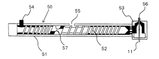
- FIG. 5 schematically shows an outline of a vent type extruder equipped with a crosshead.
- an extrusion screw 52 having a screw dam portion 57 is rotatably inserted in a cylinder 51.
- a cross head 53 is attached to the end of the cylinder 51 at the front end side of the extrusion screw 52.
- the cylinder 51 is provided with a vent port 55.
- the vent port 55 is connected to a vacuum pump (not shown), and the inside of the cylinder 51 is evacuated by the vacuum pump.
- the elastic layer material (the mixture) introduced from the material introduction port 54 is conveyed to the crosshead 53 side by the rotation of the extrusion screw 52.
- the elastic layer material conveyed to the cross head 53 is laminated on the outer periphery of the core metal 11 supplied from a core metal supply device (not shown), passes through the die 56 at the tip of the cross head, and is coextruded together with the core metal 11. .
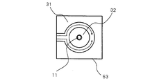
- FIG. 3 shows a schematic cross-sectional view perpendicular to the extrusion direction of the cross head 53 in order to explain the material flow in the cross head 53.
- the cross head 53 includes an outer die 31 and an inner die 32.
- the material conveyed from the cylinder is bifurcated in two directions by the inner die 32 as indicated by the arrows shown in FIG. 3 and merges again at a point (opposite side) opposite to the point where the material diverged. Extruded to cover the outer periphery.
- the junction described above is usually called a weld, and the flow path in the crosshead is longer than the other parts, and the heat history is longer. There is a tendency that unevenness in the circumferential direction occurs.
- the cylinder 51, the extrusion screw 52, and the cross head 53 of the extruder 50 are each maintained at a temperature appropriately designated by a temperature controller (not shown).
- a temperature controller not shown.
- the temperature at the time of extrusion shall be 60 degreeC or more and 110 degrees C or less.
- the surface of the elastic layer may be subjected to surface modification by irradiating the surface of the elastic layer with ultraviolet rays or an electron beam so that dirt such as toner or paper powder is difficult to adhere.
- a separate surface layer may be formed on the surface of the elastic layer.
- a known coating layer is generally used.
- a surface layer having a desired electrical resistance value by appropriately dispersing the following conductive agent in the following binder polymer or an oxyalkylene group is used.
- a sol-gel film made of polysiloxane is used.
- binder polymer examples include acrylic polymer, polyurethane, polyamide, polyester, polyolefin, and silicone.
- Conductive agents include oxides such as carbon black, graphite, titanium oxide and tin oxide; metals such as Cu and Ag; conductive particles obtained by coating the surface of the particles with oxides or metals; LiClO 4 , KSCN, NaSCN And ionic electrolytes such as LiCF 3 SO 3 .
- a coating method such as dipping, ring coating, beam coating, roll coater or spraying. And the like.
- the electrophotographic apparatus includes a charging member and an electrophotographic photosensitive member arranged so as to be capable of being charged by the charging member, and has an arrangement using the conductive member according to the present invention as the charging member.
- a device can be mentioned.
- the conductive member according to the present invention can be used for a process cartridge configured to be detachable from the main body of the electrophotographic apparatus.
- the process cartridge includes a charging cartridge and an electrophotographic photosensitive member arranged so as to be charged by the charging member, and has a configuration using the conductive member according to the present invention as the charging member. be able to.
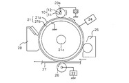
- FIG. 2 shows a schematic configuration example of an electrophotographic apparatus (electrophotographic image forming apparatus).
- a drum-shaped electrophotographic photosensitive member 21 as a member to be charged shown in FIG. 2 includes a support 21b having conductivity such as aluminum and a photosensitive layer 21a formed on the support 21b as basic constituent layers. 2 is driven to rotate at a predetermined peripheral speed in the clockwise direction in FIG.
- the charging roller 10 is disposed in contact with the electrophotographic photosensitive member 21 and charges (primary charging) the electrophotographic photosensitive member 21 to a predetermined polarity and potential.
- the charging roller 10 includes a cored bar 11 and an elastic layer 12 formed on the cored bar 11. Both ends of the cored bar 11 are pressed against the electrophotographic photosensitive member 21 by pressing means (not shown). As the photoconductor 21 is driven to rotate, it is driven to rotate.
- the electrophotographic photosensitive member 21 When a predetermined direct current (DC) bias is applied to the metal core 11 by the rubbing power source 23a connected to the power source 23, the electrophotographic photosensitive member 21 is contact-charged to a predetermined polarity and potential.
- the electrophotographic photosensitive member 21 whose peripheral surface is charged by the charging roller 10 is then subjected to exposure of target image information (laser beam scanning exposure, slit exposure of a document image, etc.) by the exposure means 24, so that the peripheral surface has a target.
- target image information laser beam scanning exposure, slit exposure of a document image, etc.
- the electrostatic latent image is sequentially visualized as a toner image by the developing means 25 having a developing roller.
- This toner image is then synchronized with the rotation of the electrophotographic photosensitive member 21 from a paper feeding unit (not shown) by the transfer unit 26 and transferred at a proper timing between the electrophotographic photosensitive member 21 and the transfer unit 26.
- a transfer material 27 such as paper.
- the transfer means 26 shown in FIG. 2 is a transfer roller connected to the power source 22, and the toner image on the electrophotographic photosensitive member 21 side is transferred to the transfer material 27 by charging the reverse polarity of the toner from the back of the transfer material 27. It will be done.
- the transfer material 27 that has received the transfer of the toner image on the surface is separated from the electrophotographic photosensitive member 21, conveyed to a fixing means (not shown), subjected to image fixing, and output as an image formed product.
- a fixing means not shown
- image fixing Alternatively, in the case of forming an image on the back surface, the image is conveyed to a re-conveying means (not shown) to the transfer unit.
- the peripheral surface of the electrophotographic photosensitive member 21 after the image transfer is subjected to pre-exposure by a pre-exposure unit (not shown), and residual charges on the electrophotographic photosensitive member 21 are removed (static elimination).
- a pre-exposure unit not shown
- residual charges on the electrophotographic photosensitive member 21 are removed (static elimination).
- known means can be used, and for example, an LED chip array, a fuse lamp, a halogen lamp, a fluorescent lamp, and the like can be preferably exemplified.
- the peripheral surface of the electrophotographic photosensitive member 21 that has been neutralized is subjected to removal of adhering contaminants such as transfer residual toner from the cleaning means 28 to be cleaned, and is repeatedly used for image formation.
- the charging roller 10 may be driven and driven by the electrophotographic photosensitive member 21 that is driven to move the surface, or may be non-rotated, or may be a predetermined direction in the forward or reverse direction of the surface movement of the electrophotographic photosensitive member 21. You may make it actively rotate at a peripheral speed.
- the exposure is performed by converting reflected light or transmitted light from a document, or reading a document into a signal, scanning a laser beam based on this signal, driving an LED array, or driving a liquid crystal shutter array.
- the conductive member of the present invention can be used as the above-described charging roller 10, developing roller, transfer roller, or the like.
- Examples of the electrophotographic apparatus that can use the conductive member of the present invention include an electrophotographic application apparatus such as a copying machine, a laser beam printer, an LED printer, or an electrophotographic plate making system.
- ⁇ Surface treatment carbon black-3> Surface-treated carbon black-3 was obtained in the same manner as surface-treated carbon black-1 except that carbon black-1 was changed to carbon black-2 (trade name: SUNBLACK720; manufactured by Asahi Carbon Co., Ltd.).
- ⁇ Surface treatment carbon black-4> Surface-treated carbon black-4 was obtained by performing the same treatment as surface-treated carbon black-1 except that carbon black-1 was changed to carbon black-3 (trade name: # 47; manufactured by Mitsubishi Chemical Corporation).
- ⁇ Surface treatment carbon black-5> Carbon black-1 was oxidized in 2N (N: grams equivalent number of reagents in 1 liter of solution) sulfuric acid for 18 hours, then filtered, and washed with water until the filtrate was neutral. . The obtained solid was dried at 80 ° C.
- ⁇ Surface treatment carbon black-6> A surface-treated carbon black-6 was obtained in the same manner as in the surface-treated carbon black-5 except that carbon black-1 was changed to carbon black-3.
- ⁇ Surface treatment carbon black-7> A surface-treated carbon black-7 was obtained by performing the same treatment as that of the surface-treated carbon black-5 except that the carbon black-1 was changed to a trade name: Raven760ULTRA (manufactured by Colombian Carbon).
- ⁇ Surface treatment carbon black-8> A surface-treated carbon black-8 was obtained by performing the same treatment as that of the surface-treated carbon black-5 except that the carbon black-1 was changed to a trade name: Printex 300 (manufactured by Evonik Industries).
- ⁇ Surface treatment carbon black-9> Surface treatment carbon black-9 was obtained by performing the same treatment as surface treatment carbon black-5 except that carbon black-1 was changed to trade name: REGAL330 (manufactured by Cabot).
- ⁇ Surface treatment carbon black-10> Surface treatment carbon black-10 was obtained in the same manner as the surface treatment carbon black-6 except that the treatment liquid used for the oxidation treatment was a 2N nitric acid aqueous solution.
- Example 1 Preparation of unvulcanized rubber composition
- TD6-15MDX 6 liter pressure kneader
- the kneaded rubber material A was mixed by the binder polymer split mixing method shown below.
- the input mass of the material was adjusted so that the filling rate of the pressure kneader was 80 vol% when all the materials were finally added.
- Conductive vulcanizing adhesive (trade name: METALOC U-20, 226 mm in the axial center of the cylindrical surface of a solid cylindrical conductive core (steel; surface is nickel-plated) 6 mm in diameter and 252 mm in length (Toyo Chemical Laboratories) was applied and dried at 80 ° C. for 30 minutes.
- the unvulcanized rubber composition is simultaneously extruded into a cylindrical shape coaxially around the core metal by extrusion molding using a cross head, and the unvulcanized rubber composition is coated on the outer periphery of the core metal.
- An unvulcanized rubber roller having a diameter of 8.8 mm was produced.
- an extruder having a cylinder diameter of 45 mm ( ⁇ 45) and an effective screw length (L) / screw diameter (D) of 20 is used, and the temperature during extrusion is 90 ° C., 90 ° C. cylinder, 90 ° C. screw. did. Both ends of the molded unvulcanized rubber roller were cut so that the axial width of the elastic layer portion was 228 mm, followed by heat treatment at 160 ° C. for 40 minutes in an electric furnace to obtain a vulcanized rubber roller. The surface of the obtained vulcanized rubber roller was polished with a plunge cut grinding type polishing machine to obtain an elastic rubber roller having a crown-shaped elastic layer with an end diameter of 8.35 mm and a center diameter of 8.50 mm.
- UV treatment was performed by irradiating the surface of the obtained elastic rubber roller with ultraviolet rays (UV) to obtain a charging roller having a surface-treated elastic layer.
- UV ultraviolet rays
- a low-pressure mercury lamp manufactured by Harrison Toshiba Lighting Co., Ltd. was used, and ultraviolet rays having a wavelength of 254 nm were irradiated so that the integrated light amount became 15000 mJ / cm 2 .
- the elastic rubber roller was irradiated with ultraviolet rays while being rotated by a roller rotating member at a speed of 60 rpm.
- the integrated light quantity of ultraviolet rays is defined as follows.
- UV integrated light quantity [mJ / cm 2 ] UV intensity [mW / cm 2 ] ⁇ irradiation time [s]
- the integrated amount of UV light can be adjusted by setting the irradiation time, lamp output, distance between the lamp and the object to be irradiated, etc.
- the total amount of UV light can be adjusted by Ushio Electric Co., Ltd. The total was measured using a trade name: UIT-150-A.
- the surface of the obtained elastic layer of the charging roller was observed with an optical microscope, and the degree of carbon black dispersion (carbon dispersion) in the elastic layer was evaluated.
- the evaluation criteria are as follows.
- A Dispersion failure of carbon black having a diameter of 20 ⁇ m or more is not observed.
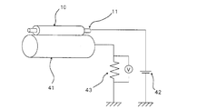
- FIG. 4 shows a schematic configuration of an apparatus for measuring the electric resistance of the charging roller.
- the charging roller 10 is pressed against both ends of the core metal 11 by a cylindrical aluminum drum 41 having a diameter of 30 mm by a pressing means (not shown), and is driven to rotate as the aluminum drum 41 rotates.
- a DC voltage was applied to the cored bar portion 11 of the charging roller 10 using an external power source 42, and the voltage applied to the reference resistor 43 connected in series to the aluminum drum 41 was measured.
- the electrical resistance of the charging roller 10 can be calculated from the measured voltage of the reference resistance 43 by the following formula.
- R Vl * Rb / Vm (R represents the electrical resistance of the charging roller, V 1 represents the applied voltage, R b represents the reference resistance value, and V m represents the measured reference resistance voltage).
- the electric resistance of the charging roller is 23 ° C. and 50% humidity R.D. H.
- the apparatus of FIG. 4 was used, and a voltage of DC 200 V was applied between the metal core and the aluminum drum for 2 seconds.
- the rotation speed of the aluminum drum at this time was 30 rpm.
- the resistance value of the reference resistance was adjusted to be 1/100 of the resistance value of the charging roller.
- Data sampling was performed at a frequency of 1000 Hz from 1 second to 1 second after voltage application, and the average value of the obtained electrical resistance was used as the resistance value of the charging roller.
- the ratio between the measured maximum value and the minimum value of the electrical resistance of the charging roller was calculated as the circumferential unevenness of the electrical resistance of the charging roller.
- the electric resistance of the charging roller was 8.0 ⁇ 10 4 ⁇ (8.0E + 04), and the circumferential unevenness of the resistance was 1.2 times.
- the MD-1 hardness of the charging roller surface was measured.
- the measurement was performed using a micro hardness meter MD-1 type (manufactured by Kobunshi Keiki Co., Ltd.) in a peak hold mode in an environment of 23 ° C. and 55% RH. More specifically, place the charging roller on a metal plate, place a metal block, and fix it easily so that it does not roll, and measure accurately from the vertical direction to the center of the charging roller with respect to the metal plate.
- the terminal was pressed and the peak value of the measurement was read for 5 seconds.
- a total of 9 points were measured at three positions in the circumferential direction at both ends and the center part 30 to 40 mm from the rubber end of the charging roller, and the average value of the obtained measured values was subjected to surface treatment.
- the hardness of the layer was taken. As a result, the hardness of the surface-treated elastic layer was 66 °.
- Example 2> A charging roller was produced in the same manner as in Example 1 except that carbon black-1 was changed to surface-treated carbon black-2. In the same manner as in Example 1, carbon (CB) dispersion, electrical resistance, circumferential unevenness of electrical resistance, and MD-1 hardness were measured.
- Example 3> A charging roller was produced in the same manner as in Example 1 except that the carbon black-1 was changed to the surface-treated carbon black-3 and the blending amount was 25 parts by mass. In the same manner as in Example 1, carbon dispersity, electrical resistance, circumferential unevenness of electrical resistance, and MD-1 hardness were measured.
- Example 4> A charging roller was produced in the same manner as in Example 1 except that the carbon black-1 was changed to the surface-treated carbon black-5 and the blending amount thereof was 28 parts by mass. In the same manner as in Example 1, carbon dispersity, electrical resistance, circumferential unevenness of electrical resistance, and MD-1 hardness were measured.
- Example 5> A charging roller was produced in the same manner as in Example 1 except that the carbon black-1 was changed to the surface-treated carbon black-6 and the blending amount was 29 parts by mass. In the same manner as in Example 1, carbon dispersity, electrical resistance, circumferential unevenness of electrical resistance, and MD-1 hardness were measured.
- a charging roller was prepared in the same manner as in Example 5 except that the binder polymer, specifically, NBR, which is a raw rubber, was not divided and the entire amount (100 parts by mass) was first mixed. Produced. In the same manner as in Example 1, carbon dispersity, electrical resistance, circumferential unevenness of electrical resistance, and MD-1 hardness were measured.
- Example 7> A charging roller was produced in the same manner as in Example 6 except that the amount of surface-treated carbon black-6 was 30 parts by mass and MT carbon was not added. In the same manner as in Example 1, carbon dispersity, electrical resistance, circumferential unevenness of electrical resistance, and MD-1 hardness were measured.
- Example 8> A charging roller was produced in the same manner as in Example 1 except that the carbon black-1 was changed to the surface-treated carbon black-7 and the blending amount was 32 parts by mass. In the same manner as in Example 1, carbon dispersity, electrical resistance, circumferential unevenness of electrical resistance, and MD-1 hardness were measured.
- Example 9> A charging roller was produced in the same manner as in Example 1 except that the carbon black-1 was changed to the surface-treated carbon black-9 and the blending amount was 31 parts by mass. In the same manner as in Example 1, carbon dispersity, electrical resistance, circumferential unevenness of electrical resistance, and MD-1 hardness were measured.
- Example 10 A charging roller was produced in the same manner as in Example 1 except that carbon black-1 was changed to surface-treated carbon black-11. In the same manner as in Example 1, carbon dispersity, electrical resistance, circumferential unevenness of electrical resistance, and MD-1 hardness were measured.
- Example 1 A charging roller was produced in the same manner as in Example 1 except that carbon black-1 was changed to carbon black-2 and the blending amount was 25 parts by mass. In the same manner as in Example 1, carbon dispersity, electrical resistance, circumferential unevenness of electrical resistance, and MD-1 hardness were measured.
- Example 2 A charging roller was produced in the same manner as in Example 1 except that carbon black-1 was changed to carbon black-3 and the blending amount was 28 parts by mass. In the same manner as in Example 1, carbon dispersity, electrical resistance, circumferential unevenness of electrical resistance, and MD-1 hardness were measured.
- ⁇ Comparative Example 3> A charging roller was produced in the same manner as in Example 1 except that the carbon black-1 was changed to carbon black-4 (trade name: Raven 2000; manufactured by Columbian Carbon Co., Ltd.) and the blending amount was 25 parts by mass. In the same manner as in Example 1, carbon dispersity, electrical resistance, circumferential unevenness of electrical resistance, and MD-1 hardness were measured.
- ⁇ Comparative example 4> A charging roller was produced in the same manner as in Example 1 except that carbon black-1 was changed to carbon black-5 (trade name: Raven760ULTRA; manufactured by Colombian Carbon Co., Ltd.) and the blending amount was 40 parts by mass. In the same manner as in Example 1, carbon dispersity, electrical resistance, circumferential unevenness of electrical resistance, and MD-1 hardness were measured.
- Example 5 A charging roller was produced in the same manner as in Example 1 except that the carbon black-1 was changed to the surface-treated carbon black-8 and the blending amount thereof was changed to 32 parts by mass. In the same manner as in Example 1, carbon dispersity, electrical resistance, circumferential unevenness of electrical resistance, and MD-1 hardness were measured.
- Example 6 A charging roller was produced in the same manner as in Example 1 except that the carbon black-1 was changed to the surface-treated carbon black-1 and the blending amount was 25 parts by mass. In the same manner as in Example 1, carbon dispersity, electrical resistance, circumferential unevenness of electrical resistance, and MD-1 hardness were measured.
- Example 7> A charging roller was produced in the same manner as in Example 1 except that carbon black-1 was changed to surface-treated carbon black-4. In the same manner as in Example 1, carbon dispersity, electrical resistance, circumferential unevenness of electrical resistance, and MD-1 hardness were measured.
- Table 6 shows the characteristics of the carbon black used in each of the above examples and comparative examples, and the analysis results of the amount of gas generated by heating.
- the average primary particle diameter and DBP oil absorption of carbon black were measured by the method mentioned above.
- the amount of gas generated by heating of carbon black that is, the measurement of the surface functional group of carbon black was measured by the following method.
- Tables 7 and 8 show the compositions and evaluation results of the charging rollers prepared in the above Examples and Comparative Examples.
- the carbon black 2 used in Comparative Example 1 and the surface-treated carbon black 10 used in Comparative Example 8 both generate CO and CO 2 in the carbon surface functional group analysis.
- the total amount was 0.80% by mass or more.
- the circumferential unevenness of the electrical resistance in the charging rollers manufactured in Comparative Examples 1 and 8 was as large as 2.0 times or more.
- the evaluation of the degree of dispersion of the carbon black in the elastic layer was D rank.
- the carbon black 5 used in Comparative Example 4 has an average primary particle diameter of more than 30 nm, and it is desired to add a relatively large amount of carbon black for adjusting the electric resistance, and the hardness is as high as 75 ° or more. . Also, the circumferential unevenness of the electrical resistance of the charging roller was more than doubled.
- Both the surface-treated carbon black-1 used in Comparative Example 6 and the surface-treated carbon black-4 used in Comparative Example 7 have a small amount of carbon surface functional groups, and the degree of dispersion of carbon black in the elastic layer is evaluated as D. Rank.
- Examples 1 to 10 using carbon black satisfying the first CB requirement have an MD-1 hardness of less than 75 ° and the circumferential direction of the roller electrical resistance. Unevenness was also less than twice.
Landscapes
- Physics & Mathematics (AREA)
- General Physics & Mathematics (AREA)
- Engineering & Computer Science (AREA)
- Plasma & Fusion (AREA)
- Electrostatic Charge, Transfer And Separation In Electrography (AREA)
- Compositions Of Macromolecular Compounds (AREA)
- Electrophotography Configuration And Component (AREA)
Abstract
加工条件による電気抵抗の変動が小さく、均一な電気抵抗を有する導電性部材を提供する。導電性部材は、導電性支持体と、導電性の弾性層とを有し、該弾性層は、電子導電剤とバインダーポリマーとを含む混合物またはその硬化物であり、該電子導電剤が下記の特性を満たすカーボンブラックを含む。 (i)平均一次粒子径が20nm以上30nm以下、 (ii)DBP吸油量が40ml/100g以上70ml/100g以下であり、加熱ガス発生分析により発生するCOおよびCO2の総量が、該カーボンブラック基準で、0.30質量%以上0.80質量%以下、 (iii)該加熱ガス発生分析により発生するSO2の量が、該カーボンブラック基準で、0.05質量%以上。
Description
本発明は、電子写真装置において感光体に当接させて使用できる帯電部材等の導電性部材、電子写真装置およびプロセスカートリッジに関する。
電子写真画像形成装置においては、帯電部材、現像部材、転写部材及び給紙部材などに、導電性の弾性層を有する導電性部材が用いられている。かかる導電性の弾性層は、例えば、電気抵抗値が体積固有抵抗率で1×10³Ω・cm以上1×10⁹Ω・cm以下程度の半導電性を有することが望まれている。
弾性層には、ベースゴムにカーボンブラックを配合した導電性ゴムを使用することが知られている。
弾性層には、ベースゴムにカーボンブラックを配合した導電性ゴムを使用することが知られている。
特許文献1には、カーボンブラックの添加により体積固有抵抗を調整してなる半導電性ゴム材料からなる弾性体層を具備したOA機器用部材が開示されている。そして、特許文献1には、カーボンブラックとして、窒素吸着比表面積が20~150m2/g、DBP吸油量が60~180ml/100gのものを用いることが記載され、また、実施例においては、窒素吸着比表面積が32m2/g、DBP吸油量が140ml/100gであるカーボンブラック(商品名:シーストG-SVH;東海カーボン社製)を用いたことが記載されている。そして、引用文献1は、DBP吸油量の数値範囲の意義について、60ml/100g未満の場合、ストラクチャーの発達が低すぎるため、導電性を出すために多量にカーボンブラックを添加する必要があり、ゴム硬度の上昇を招来すること、一方、180ml/100gを超えるとストラクチャーが発達し過ぎて、少量の配合でも弾性層の電気抵抗値が変化し過ぎるため、電気抵抗の調整が難しくなることを挙げている。
ところで、一般に、カーボンブラックのゴム中への分散性は、カーボンブラックの比表面積を下げること、つまり、粒径を大きくすること、または、ストラクチャーを増加させることによって改善できることが知られている。そして、カーボンブラックのストラクチャーの発達の程度は、DBP吸油量によって評価できる。これは、カーボンブラックのアグリゲート間の空隙率がカーボンブラックのストラクチャーと正の相関を有するためである。そして、現在、市場に流通しているカーボンブラックのDBP吸油量は、40~180ml/100g程度である。
したがって、上記特許文献1に記載されたカーボンブラックは、ゴム中への分散性に優れた、DBP吸油量が大きいものを選択していると理解することができる。
したがって、上記特許文献1に記載されたカーボンブラックは、ゴム中への分散性に優れた、DBP吸油量が大きいものを選択していると理解することができる。
本発明者らの検討によると、特許文献1に記載されているようなDBP吸油量の大きなカーボンブラックをゴム中に分散させたゴム組成物を用いて形成した導電性弾性層に大きな電気抵抗のムラが生じる場合があることを見出した。具体的には、DBP吸油量の大きいカーボンブラックとゴムとを混練りして得た導電性ゴム組成物をクロスヘッドを用いて芯金とともに共押し出しして形成してなるローラ形状の導電性部材の、芯金の周囲を被覆する導電性の弾性層の電気抵抗が周方向でバラつく場合があった。
そこで、本発明の目的は、電気抵抗のムラの少ない導電性の弾性層を具備してなる電子写真用の導電性部材を提供することを目的とする。また、本発明の他の目的は、高品位な電子写真画像の形成に寄与するプロセスカートリッジおよび電子写真装置を提供することにある。
本発明によれば、
導電性支持体と、導電性の弾性層とを有する導電性部材であって、
該弾性層は、電子導電剤とバインダーポリマーとを含む混合物または該混合物の硬化物であり、
該電子導電剤が下記特性(i)~(iii)を有するカーボンブラックを含む導電性部材が提供される:
(i)平均一次粒子径が20nm以上30nm以下;
(ii)DBP吸油量が40ml/100g以上70ml/100g以下;
(iii)加熱ガス発生分析により発生するCOおよびCO2の総量が、該カーボンブラック基準で、0.30質量%以上0.80質量%以下、SO2の量が、該カーボンブラック基準で、0.05質量%以上。
導電性支持体と、導電性の弾性層とを有する導電性部材であって、
該弾性層は、電子導電剤とバインダーポリマーとを含む混合物または該混合物の硬化物であり、
該電子導電剤が下記特性(i)~(iii)を有するカーボンブラックを含む導電性部材が提供される:
(i)平均一次粒子径が20nm以上30nm以下;
(ii)DBP吸油量が40ml/100g以上70ml/100g以下;
(iii)加熱ガス発生分析により発生するCOおよびCO2の総量が、該カーボンブラック基準で、0.30質量%以上0.80質量%以下、SO2の量が、該カーボンブラック基準で、0.05質量%以上。
また、本発明によれば、電子写真装置の本体に着脱可能に構成されているプロセスカートリッジであって、帯電部材と、該帯電部材によって帯電可能に配置されている電子写真感光体とを具備しているプロセスカートリッジが提供される。
更に本発明によれば、帯電部材と、該帯電部材によって帯電可能に配置されている電子写真感光体とを具備している電子写真装置が提供される。
本発明によれば、電気抵抗のムラの小さい導電性弾性層を備えた電子写真用の導電性部材を得ることができる。また、本発明によれば、高品位な電子写真画像の形成に寄与するプロセスカートリッジおよび電子写真装置を得ることができる。
本発明者らは、DBP吸油量の大きいカーボンブラックがゴム中に分散されてなる導電性ゴム組成物を用いて形成された導電性弾性層に電気抵抗のムラが生じる理由について検討した。その結果、DBP吸油量の大きいカーボンブラックはゴムに対する分散性が良好であるため、当該カーボンブラックを含むゴム組成物中におけるカーボンブラックの分散状態が、当該ゴム組成物に対するせん断力(シェア)のわずかな変動によって極めて容易に変化してしまうことを見出した。
通常、カーボンブラックをゴム中に分散させる際には、高いせん断力を加える。その後、所定の形状の弾性層を得るために、当該ゴム組成物の押出し成形を行う。このときに、カーボンブラックのゴムに対する分散性が高い場合、押出し成形の際にゴム組成物に加わるせん断力のわずかな変動によってもゴム中のカーボンブラックの存在状態が容易に変化してしまう。これが、DBP給油量の高いカーボンブラックを用いた場合に導電性弾性層に局所的に電気抵抗ムラが生じやすい理由であると考えられる。
通常、カーボンブラックをゴム中に分散させる際には、高いせん断力を加える。その後、所定の形状の弾性層を得るために、当該ゴム組成物の押出し成形を行う。このときに、カーボンブラックのゴムに対する分散性が高い場合、押出し成形の際にゴム組成物に加わるせん断力のわずかな変動によってもゴム中のカーボンブラックの存在状態が容易に変化してしまう。これが、DBP給油量の高いカーボンブラックを用いた場合に導電性弾性層に局所的に電気抵抗ムラが生じやすい理由であると考えられる。
かかる考察に基づき、本発明者らは、導電性弾性層に含有させるカーボンブラックとして、ゴムに対する分散性が悪い、小粒径で、かつ、低ストラクチャーのカーボンブラック、具体的には、平均一次粒子径が20nm以上30nm以下、DBP吸油量が40ml/100g以上70ml/100g以下のカーボンブラックを用いることを試みた。
すなわち、このようなカーボンブラックをゴムに混入したゴム組成物に高いせん断力を加えることで、ゴム中に当該カーボンブラックを良好に分散させることができれば、その後の押出成形の際の低いせん断力ではカーボンブラックの分散状態が変化せず、電気抵抗ムラの小さい導電性弾性層を得られるものと考えた。しかしながら、かかるカーボンブラックはゴムに対する分散性が非常に乏しく、高いせん断力を加えても、ゴム中に良好に分散させることが困難であった。
その結果、得られた帯電部材の弾性層中にカーボンブラックの不十分な分散によるカーボンブラックの凝集塊が観察される場合があった。そして、かかる帯電部材を用いて電子写真感光体を帯電させると、弾性層中のカーボンブラック凝集塊の存在に由来する帯電不良、およびそれに起因する電子写真画像への斑点の発生がみられる場合があった。
その結果、得られた帯電部材の弾性層中にカーボンブラックの不十分な分散によるカーボンブラックの凝集塊が観察される場合があった。そして、かかる帯電部材を用いて電子写真感光体を帯電させると、弾性層中のカーボンブラック凝集塊の存在に由来する帯電不良、およびそれに起因する電子写真画像への斑点の発生がみられる場合があった。
そこで、本発明者らは、カーボンブラックの表面官能基に着目した。カーボンブラックは、通常、その表面にカルボキシル基、水酸基、キノン基、ラクトン基等の官能基を有する。そして、これらの表面官能基は、カーボンブラックのゴムに対する分散性にもある程度影響を与える。すなわち、表面官能基が多いカーボン程、ゴムへの分散が容易になる傾向がある。
そこで、本発明者らは分散性と電気抵抗の安定性とを両立させるため、小粒子径で、DBP吸油量が小さく、かつ、表面官能基の多いカーボンブラックを用いて検討を行った。その結果、ゴムに対する分散性は改善されたものの、電気抵抗がゴム組成物の加工工程において徐々に変動してしまうという新たな課題が見出された。
そこで、表面官能基の多いカーボンブラックが上記の課題をもたらす理由について、さらに検討を行った。その結果、カーボンブラックの表面に存在する官能基にはカーボンブラックの表面から容易に脱離し易いもの、すなわち、安定性の低いものと、容易には脱離しない、安定性の高いものとがあること、そして、安定性の低い官能基が表面に多く存在するカーボンブラックの場合、ゴム中への分散工程で当該表面官能基の存在量が変化し、電気抵抗が変動しやすいことが判明した。具体的には、カルボキシル基、キノン基、ラクトン基等の炭素原子と酸素原子と水素原子とからなる官能基類は安定性が低く、ゴム組成物の加工工程における電気抵抗の変動を生じさせ易かった。これに対して、スルホニル基等の硫黄原子を含有する官能基は安定性が高く、ゴム組成物の加工工程における電気抵抗の変動が生じにくいことを見出した。
以上の知見を踏まえて、本発明者らは、粒子径が小さく、低ストラクチャーであって、かつ、炭素原子と酸素原子と水素原子とからなる官能基が少なく、硫黄原子を含有する官能基が多いカーボンブラックが、本発明の目的の達成に適したものであるとの結論に至った。すなわち、このようなカーボンブラックは、ゴム組成物に対して適度な分散性を有し、かつ、ゴム組成物中における分散状態が、ゴム組成物に加わるせん断力のわずかな変動に対しても変化することが少ない。そのため、電気抵抗のムラの小さい導電性弾性層を量産する上で極めて好適なものといえる。
以下、本発明の好適な実施の形態について説明する。
<導電性部材>
本発明の導電性部材は、導電性支持体と、導電性の弾性層とを有する。また、導電性部材は、支持体と弾性層との間や、弾性層表面に他の層(例えば、接着層や表面層)を有することもできる。本発明の導電性部材は、電子写真装置及び静電記録装置等の画像形成装置に用いる導電性部材として使用することができる。本発明の導電性部材は、これらの画像形成装置に用いる、帯電部材、現像部材、転写部材、及び給紙部材などに使用可能である。なお、導電性部材の形状は適宜選択することができ、例えば、ローラ形状やベルト形状とすることができる。以降、特に、ローラ形状の帯電部材(帯電ローラ)に着目して説明を行う。
本発明の導電性部材は、導電性支持体と、導電性の弾性層とを有する。また、導電性部材は、支持体と弾性層との間や、弾性層表面に他の層(例えば、接着層や表面層)を有することもできる。本発明の導電性部材は、電子写真装置及び静電記録装置等の画像形成装置に用いる導電性部材として使用することができる。本発明の導電性部材は、これらの画像形成装置に用いる、帯電部材、現像部材、転写部材、及び給紙部材などに使用可能である。なお、導電性部材の形状は適宜選択することができ、例えば、ローラ形状やベルト形状とすることができる。以降、特に、ローラ形状の帯電部材(帯電ローラ)に着目して説明を行う。
(帯電ローラ)
図1に、本発明に係る導電性部材の一例として、帯電ローラ10の模式的断面図を示す。帯電ローラ10は、導電性支持体である芯金11と、その外周に設けられた導電性の弾性層12とから構成されることができ、上述したように、必要に応じて、弾性層12の外側(外周面)に表面層13を設けることができる。図1に示す帯電ローラ10は、芯金11と、弾性層12と、表面層13とから構成されている。
図1に、本発明に係る導電性部材の一例として、帯電ローラ10の模式的断面図を示す。帯電ローラ10は、導電性支持体である芯金11と、その外周に設けられた導電性の弾性層12とから構成されることができ、上述したように、必要に応じて、弾性層12の外側(外周面)に表面層13を設けることができる。図1に示す帯電ローラ10は、芯金11と、弾性層12と、表面層13とから構成されている。
帯電ローラの弾性層の表面のMD-1硬度の好ましい範囲としては、40°以上、特には、60°以上であり、90°未満、特には75°未満である。MD-1硬度の値を40°以上とすることは、表面への圧縮永久歪みの発生の抑制に資する。また、MD-1硬度の値を90°未満とすることは、トナー等の付着のより一層の抑制に寄与する。
また、帯電ローラの電気抵抗は、耐リーク性の観点から、好ましくは1×10³Ω以上、より好ましくは1×10⁴Ω以上であり、帯電性能の観点から、好ましくは1×10⁷Ω以下、より好ましくは1×10⁶Ω以下である。
(導電性支持体)
本発明に用いる導電性支持体は、特に限定されず、例えば、電子写真装置の分野で公知の導電性支持体を用いることができる。導電性支持体の形状は、導電性部材の形状に応じて適宜選択することができる。
本発明に用いる導電性支持体は、特に限定されず、例えば、電子写真装置の分野で公知の導電性支持体を用いることができる。導電性支持体の形状は、導電性部材の形状に応じて適宜選択することができる。
(導電性の弾性層)
本発明に用いる導電性の弾性層は、バインダーポリマーと、電子導電剤とを含む混合物またはその硬化物からなる。そして、電子導電剤として、特定のカーボンブラック(後述する第1のCB)を含む。
本発明に用いる導電性の弾性層は、バインダーポリマーと、電子導電剤とを含む混合物またはその硬化物からなる。そして、電子導電剤として、特定のカーボンブラック(後述する第1のCB)を含む。
・バインダーポリマー
バインダーポリマーは、導電性部材の実使用温度範囲でゴム弾性を示す材料であれば特に限定されるものではない。具体的なバインダーポリマー(ゴム材料)としては、以下の原料ゴムに架橋剤を配合した熱硬化性のゴム材料や、以下の熱可塑性エラストマーを挙げることができる。
バインダーポリマーは、導電性部材の実使用温度範囲でゴム弾性を示す材料であれば特に限定されるものではない。具体的なバインダーポリマー(ゴム材料)としては、以下の原料ゴムに架橋剤を配合した熱硬化性のゴム材料や、以下の熱可塑性エラストマーを挙げることができる。
原料ゴムとしては、天然ゴム(NR)、イソプレンゴム(IR)、ブタジエンゴム(BR)、スチレン-ブタジエン(SBR)、ブチルゴム(IIR)、エチレン-プロピレン-ジエン3元共重合体ゴム(EPDM)、エピクロルヒドリンホモポリマー(CO)、エピクロルヒドリン-エチレンオキサイド共重合体(ECO)、エピクロルヒドリン-エチレンオキサイド-アリルグリシジルエーテル3元共重合体(AGE-CHC)、アクリロニトリル-ブタジエン共重合体(NBR)、アクリロニトリル-ブタジエン共重合体の水添物(H-NBR)、クロロプレンゴム(CR)、アクリルゴム(ACM、ANM)等が挙げられる。
架橋剤としては、硫黄、過酸化物等が挙げられる。
また、熱可塑性エラストマーとしては、ポリオレフィン系熱可塑性エラストマー、ポリスチレン系熱可塑性エラストマー、ポリエステル系熱可塑性エラストマー、ポリウレタン系熱可塑性エラストマー、ポリアミド系熱可塑性エラストマー、塩化ビニル系熱可塑性エラストマー等が挙げられる。
・カーボンブラック
本発明に用いるカーボンブラック(第1のCB)は、下記特性(i)~(iii):(i)平均一次粒子径が20nm以上30nm以下;
(ii)DBP(フタル酸ジブチル)吸油量が40ml/100g以上70ml/100g以下;
(iii)加熱ガス発生分析により発生するCOおよびCO2の総量が、該カーボンブラック基準で、0.30質量%以上0.80質量%以下、SO2の量が、該カーボンブラック基準で、0.05質量%以上
を有するものである。
上記特性(i)および(ii)は、上記第1のCBが、ゴム用カーボンブラックの中でも粒子径が最も小さく、かつ、ストラクチャーが最も発達していない範疇に属するものであることを意味している。すなわち、第1のCBは、その粒子径およびDBP吸油量の観点からはバインダーポリマーへの分散性が低いものである。
本発明に用いるカーボンブラック(第1のCB)は、下記特性(i)~(iii):(i)平均一次粒子径が20nm以上30nm以下;
(ii)DBP(フタル酸ジブチル)吸油量が40ml/100g以上70ml/100g以下;
(iii)加熱ガス発生分析により発生するCOおよびCO2の総量が、該カーボンブラック基準で、0.30質量%以上0.80質量%以下、SO2の量が、該カーボンブラック基準で、0.05質量%以上
を有するものである。
上記特性(i)および(ii)は、上記第1のCBが、ゴム用カーボンブラックの中でも粒子径が最も小さく、かつ、ストラクチャーが最も発達していない範疇に属するものであることを意味している。すなわち、第1のCBは、その粒子径およびDBP吸油量の観点からはバインダーポリマーへの分散性が低いものである。
上記混合物及び上記弾性層中の第1のCBの配合割合、第1のCBの含有量はいずれも、電気抵抗の安定性の維持の観点から、バインダーポリマーまたはその硬化物100質量部に対して、好ましくは5質量部以上、より好ましくは15質量部以上である。さらに、弾性層硬度の適正化の観点から、好ましくは60質量部以下、より好ましくは40質量部以下である。
本発明に用いるカーボンブラックの平均一次粒子径は、原料の段階でも、上記混合物の段階でも測定することができる。しかしながら、第1のCB以外に、他のカーボンブラック(例えば、第2のCB)を併用する場合は、原料の段階で各カーボンブラックの平均一次粒子径を測定することが好ましい。
原料の段階でカーボンブラックの平均一次粒子径を測定する場合は、原料のカーボンブラックを超音波洗浄法により周波数200KHzで30分間クロロホルムに分散させた分散液を調製したのち、この分散液を例えば銅からなる支持膜に固定した試料を作製する。
また、カーボンブラックがバインダーポリマー中に分散された混合物の段階でカーボンブラックの平均一次粒子径を測定する場合は、ミクロトームを用いて、この混合物から厚さ100nmの超薄切片を作製し、支持膜に固定した試料を作製する。次に、これらの試料を電子顕微鏡で観察し、80000~100000倍の倍率で撮影する。そして、得られた写真からランダムに100個のカーボンブラック粒子について写真上の直径と写真の拡大倍率により粒子径を計算して算術平均粒子直径を求め、この算術平均粒子直径をカーボンブラックの平均一次粒子径とする。
また、本発明に用いるカーボンブラックのDBP吸油量は、JIS K6217-4(2001年)に記載の方法で測定することができる。
カーボンブラック表面には、上述したように官能基が存在する。これらの官能基は不活性ガス(例えばヘリウムガス)中でカーボンブラックを加熱することによって発生するガスを分析することによって定性及び定量することができる。カーボンブラックの表面官能基がケトン基、及びキノン基等のカルボニル基を有する基である場合、このカーボンブラックを加熱した際に発生するガスは一酸化炭素(CO)である。また、表面官能基がカルボキシル基、ラクトン基、及びエステル基等の場合は二酸化炭素(CO2)が発生し、表面官能基がスルホニル基等の場合は二酸化硫黄(SO2)が発生する。カーボンブラックの表面官能基を測定する具体的方法としては、例えば、加熱発生ガス分析(Temperature Programmed Desorption-Mass Spectrometry:TPD-MS法)を挙げることができる。
そして、第1のCBは、TPD-MS法でCO又はCO2として測定される発生ガスの総量が、このカーボンブラック基準、即ち第1のCBを100質量%とした時に、0.30質量%以上0.80質量%以下であるという特性を有する。また、第1のCBは、TPD-MS法でSO2として測定される発生ガス量が、第1のCB基準で、0.05質量%以上であるという特性をも有する。
すなわち、第1のCBは、TPD-MS法において、発生するCO及びCO2の総量が0.30~0.80質量%、かつ、発生するSO2の量が0.05質量%以上となる種類及び量の表面官能基を有する。この発生ガス量を満たすことによって、第1のCB中に、炭素原子と酸素原子と水素原子とからなる安定性の低い官能基量を少なく、かつ、硫黄原子を含有する安定性の高い官能基を多く含有することができる。
COおよびCO2の発生総量を0.30質量%以上、かつ、SO2発生量を0.05質量%以上とすることで、小粒径で、かつ、DBP吸油量も小さいカーボンブラックのバインダーポリマー中への分散性の乏しさを補うことができているものと考えらえる。これは、バインダーポリマーとの濡れ性(親和性)が維持されるためと考えらえる。また、COおよびCO2発生量が0.80質量%以下の場合には、加工工程におけるカーボンブラックの表面官能基量の変化が小さく、加工条件における電気抵抗の変動を抑えることができる。
なお、これらの発生ガス量の要件を満たせば、第1のCBにおける表面官能基の具体的な種類(例えば、キノン基やラクトン基等)は、特に限定されない。
さらに、第1のCBにおける第1のCB基準でのSO2発生量は、分散性の観点から、0.06質量%以上が好ましい。また、上限値としては特に限定されないが、電気抵抗の適正化の観点から、好ましくは0.15質量%以下である。
さらに、第1のCBにおける第1のCB基準でのSO2発生量は、分散性の観点から、0.06質量%以上が好ましい。また、上限値としては特に限定されないが、電気抵抗の適正化の観点から、好ましくは0.15質量%以下である。
本発明で使用する第1のCBは前述した、平均一次粒子径、DBP吸油量、及び発生ガス量(即ち表面官能基量)の各要件をいずれも満足するものであれば、市販のカーボンブラックを用いても良く、市販品のカーボンブラックに対して表面処理を行ったものでも良い。第1のCBの市販品としては、コロンビヤンカーボン社の商品名:Raven1170がある。なお、本発明者らが検討を行った市販カーボンブラック及び本発明者らが調査した公知資料において、上述した要件を満たすカーボンブラック(第1のCB)は上記Raven1170以外に確認されなかった。
市販のカーボンブラックの表面処理を行う場合、その表面処理方法は特に限定されるものではなく、一般的に知られた処理方法を使用することができる。具体的にカーボンブラック表面の官能基を減らす方法としては、不活性ガス中でカーボンブラックを加熱処理する方法が挙げられる。カルボニル基、カルボキシル基等のCOやCO2として測定される官能基をカーボンブラック表面に付与する方法としては、例えば以下の方法が挙げられる。
即ち、空気、オゾン、酸素、NOx等の酸化性ガス雰囲気にカーボンブラックを曝す方法や、カーボンブラックを低温酸素プラズマ処理する方法、過酸化水素、次亜ハロゲン酸塩、重クロム酸塩、過マンガン酸塩、硝酸等の酸化水溶液中でカーボンブラックを撹拌処理する方法が挙げられる。スルホニル基等のSO2として測定される官能基をカーボンブラック表面に付与する方法としては、例えば、硫酸水溶液中でカーボンブラックを撹拌処理する方法が挙げられる。
即ち、空気、オゾン、酸素、NOx等の酸化性ガス雰囲気にカーボンブラックを曝す方法や、カーボンブラックを低温酸素プラズマ処理する方法、過酸化水素、次亜ハロゲン酸塩、重クロム酸塩、過マンガン酸塩、硝酸等の酸化水溶液中でカーボンブラックを撹拌処理する方法が挙げられる。スルホニル基等のSO2として測定される官能基をカーボンブラック表面に付与する方法としては、例えば、硫酸水溶液中でカーボンブラックを撹拌処理する方法が挙げられる。
本発明では、弾性層の形成に用いる混合物に、上述した第1のCBと共に、大粒子径かつ低ストラクチャーのカーボンブラック(第2のCB)を分散補助剤として配合することが好ましい。この第2のCBと、小粒子径かつ低ストラクチャーで、加熱した際にCOまたはCO2を発生する官能基が少ない第1のCBとを併用することで、以下のことが可能になる。即ち、ゴム組成物の混合工程(混合物調製工程)におけるバインダーポリマー中へのカーボンブラック(特に、第1のCB)の分散を促進し、バインダーポリマー中へのカーボンブラックの均一分散を容易に行うことができる。
本発明に係る弾性層は、上記第1のCBに加えて、下記特性(iv)及び(v)を有するカーボンブラック(第2のCB)を含有してもよい。
(iv)平均一次粒子径が、70nm以上300nm以下、好ましくは100nm以上300nm以下;
(v)DBP吸油量が20ml/100g以上70ml/100g以下、好ましくは20ml/100g以上50ml/100g以下。
(iv)平均一次粒子径が、70nm以上300nm以下、好ましくは100nm以上300nm以下;
(v)DBP吸油量が20ml/100g以上70ml/100g以下、好ましくは20ml/100g以上50ml/100g以下。
上記特性(iv)は、第2のCBが、ゴム用カーボンブラックとしては、粒径が大きい範疇に属するものであることを意味する。また、上記特性(v)は、ゴム用カーボンブラックとしては、ストラクチャーが未発達であるものの範疇に属するものであることを意味する。そしてこれらの特性を備える第2のCBは、ゴム組成物中では、導電パスの形成に必要なカーボンブラックのネットワーク構造を極めて形成しにくい。そのため、導電性弾性層の電気抵抗には殆んど影響を与えないものと考えられる。
一方、第2のCBは、大きい粒径を有するため、粒径が極めて小さい第1のCBの混合物中における凝集を阻害する。そのため、第2のCBを第1のCBと共にバインダーポリマー中に含有させることで、第1のCBをバインダーポリマー中に分散させる分散剤として機能するものと考えられる。
第2のCBとしては、具体的には、ASTM D1765でグループ9に分類されるMedium Thermalカーボン(MTカーボン)や、Semi Reinforcing Furnace カーボン (SRFカーボン)等を挙げることができる。この中でも、カーボンブラックの分散促進の観点と弾性体層の硬度上昇を抑える観点から、第2のCBとしては、MTカーボンを用いることが好ましい。
弾性層の形成に用いる上記混合物中の第2のCBの含有割合は、分散性の向上の観点から、バインダーポリマーまたはその硬化物100質量部に対して、好ましくは10質量部以上、より好ましくは20質量部以上であり、硬度の適正化の観点から、好ましくは60質量部以下、より好ましくは50質量部以下である。
・他の成分
さらに弾性層の材料(上記混合物)には、必要に応じてゴムの配合剤として一般に用いられている充填剤、加工助剤、架橋助剤、架橋促進剤、架橋促進助剤、架橋遅延剤等を添加することができる。
・混合物の作製方法
これらの原料(カーボンブラック、バインダーポリマー、及び必要に応じた他の成分)の混合方法としては、バンバリーミキサーや加圧式ニーダー等の密閉型混合機を使用した混合方法や、オープンロールのような開放型の混合機を使用した混合方法等が例示できる。これらの混合方式の中でも密閉型混合機を使用した混合方法が、混合効率が高く、より好ましい。バンバリーミキサーや加圧式ニーダー等の密閉型混合機においては、バインダーポリマー中にカーボンブラックを混合する際に高シェア(高せん断)での混合が可能である。バインダーポリマー中への分散性が比較的低い導電粒子である第1のCBを、MTカーボン等の第2のCBと共に、分散混合工程において高シェアでバインダーポリマー中に分散させることで、以下のことが可能になる。即ち、混合以降の導電性部材を得るまでの加工工程においてカーボンブラックの分散に変動がない材料を容易に得ることができる。
・他の成分
さらに弾性層の材料(上記混合物)には、必要に応じてゴムの配合剤として一般に用いられている充填剤、加工助剤、架橋助剤、架橋促進剤、架橋促進助剤、架橋遅延剤等を添加することができる。
・混合物の作製方法
これらの原料(カーボンブラック、バインダーポリマー、及び必要に応じた他の成分)の混合方法としては、バンバリーミキサーや加圧式ニーダー等の密閉型混合機を使用した混合方法や、オープンロールのような開放型の混合機を使用した混合方法等が例示できる。これらの混合方式の中でも密閉型混合機を使用した混合方法が、混合効率が高く、より好ましい。バンバリーミキサーや加圧式ニーダー等の密閉型混合機においては、バインダーポリマー中にカーボンブラックを混合する際に高シェア(高せん断)での混合が可能である。バインダーポリマー中への分散性が比較的低い導電粒子である第1のCBを、MTカーボン等の第2のCBと共に、分散混合工程において高シェアでバインダーポリマー中に分散させることで、以下のことが可能になる。即ち、混合以降の導電性部材を得るまでの加工工程においてカーボンブラックの分散に変動がない材料を容易に得ることができる。
さらに、上記混合工程においては、バインダーポリマーを分割して、カーボンブラック等の他の原料と段階的に混合することが好ましい。例えば、バインダーポリマーの総質量の2/3とカーボンブラック等の配合剤を混合した後に、残りの1/3のバインダーポリマーを混合する。このように分割した混合を行うことで、カーボンブラック分散時における、バインダーポリマーに対するカーボンブラックの見かけの質量比を高くすることができ、より高シェアな分散が可能となる。カーボンブラック分散時のカーボンブラック濃度と混合以降の成形加工時のカーボンブラック濃度が異なることにより、成形加工時のカーボンブラック分散状態はより一層安定なものとなる。すなわち、混合時はカーボンブラック濃度が高く、カーボンブラックの分散が進みやすいが、成形時はカーボンブラック濃度が低いため、分散状態の変化は小さくなる。具体的には、バインダーポリマーは、まず、バインダーポリマーの総質量の1/2以上2/3以下の量をカーボンブラック等と混合した後、残りのバインダーポリマーを混合することが好ましい。
なお、この分割混合するバインダーポリマーとは、バインダーポリマーとして熱硬化性ゴム材料を用いた場合は原料ゴムを指し、バインダーポリマーとして熱可塑性エラストマーを用いた場合は熱可塑性エラストマーを指す。
密閉型混合機を用いたバインダーポリマーの分割混合は、混合ステージを1ステップで行なっても、2ステップ以上の多段階で行っても構わないが、生産効率を考慮すれば、1ステップで行うことが好ましい。ここでの混合ステップとは、密閉型混合機に材料を投入し、混合した後、混合した材料を混合機から取り出すまでをいう。1ステップでの分割混合の場合、例えば、バインダーポリマーの総質量の1/2量とカーボンブラック全量とを混合する。この場合、混合加工時の混合翼のトルクチャートや目視判定によって、カーボンブラックがバインダーポリマー中に混合されたことを確認した後に、残りのバインダーポリマーを追加添加して混合する。
しかしながら、1ステップ混合の場合、混合機内の材料充填率は、カーボンブラックの混合時点では低くなっている。密閉式混合機においては、混合に適した材料充填率が、混合機の仕様等によって異なるが、ある範囲で決まっており、1ステップ混合の条件によっては充填量不足で混合できない場合がある。この様な場合には、例えば、バインダーポリマーの総質量の1/2量とカーボンブラック全量の場合と同じ配合比率で、混合機の最適充填率となる量のバインダーポリマー及びカーボンブラックを混合した後、一旦、混合機から取り出す。
その後、取出した混合材料と残りのバインダーポリマーとが、目標とする配合比率、及び、最適充填率になる様に質量調整し、再度、混合機で混合する。このような混合を2ステップ混合という。
その後、取出した混合材料と残りのバインダーポリマーとが、目標とする配合比率、及び、最適充填率になる様に質量調整し、再度、混合機で混合する。このような混合を2ステップ混合という。
カーボンブラック分散時の混合機の最適充填率は、用いるミキサーの種類や配合内容によって異なるが、カーボンブラック分散時で50vol%以上70vol%以下とすることが好ましい。充填率が50vol%以上であれば、混合を1ステップで行ったとしても、シェアを容易にかけることができ、混合が容易に行える。また、充填率が70vol%以下であれば、カーボンブラックの凝集塊の発生をより確実に抑制することができる。
・導電性部材の作製方法
導電性部材の形成方法としては、電子写真装置の分野で公知の方法を適用することができ、例えば、以下の方法を用いることができる。
即ち、未加硫の上記混合物(混合されたゴム組成物)を押出機によりチューブ状に押出成形し、これを加硫缶で加硫成形したものに芯金を圧入後、表面を研磨して所望の外径とする方法を用いることができる。また、加硫後の上記混合物(混合されたゴム組成物)を、クロスヘッドを装着した押出機により、芯金を中心に円筒形に共押出し、所望の外径の金型内部に固定、加熱し、成形体を得る方法を用いることができる。なお、これらのゴム組成物は、電気抵抗値が体積固有抵抗率で1×10³Ω・cm以上1×10⁹Ω・cm以下程度の半導電性ゴム組成物であることができる。
導電性部材の形成方法としては、電子写真装置の分野で公知の方法を適用することができ、例えば、以下の方法を用いることができる。
即ち、未加硫の上記混合物(混合されたゴム組成物)を押出機によりチューブ状に押出成形し、これを加硫缶で加硫成形したものに芯金を圧入後、表面を研磨して所望の外径とする方法を用いることができる。また、加硫後の上記混合物(混合されたゴム組成物)を、クロスヘッドを装着した押出機により、芯金を中心に円筒形に共押出し、所望の外径の金型内部に固定、加熱し、成形体を得る方法を用いることができる。なお、これらのゴム組成物は、電気抵抗値が体積固有抵抗率で1×10³Ω・cm以上1×10⁹Ω・cm以下程度の半導電性ゴム組成物であることができる。
なお、バインダーポリマーとして例えば熱硬化性のゴム材料を用いた場合は、例えば加熱することによって、このゴム材料を含む混合物を硬化することができ、弾性層を形成することができる。この加熱条件としては、例えば、140℃以上180℃以下の温度で、10分以上60分以下とすることができる。
上述した方法の中でも生産性が良好なことから、クロスヘッド押出成形法が好適である。図5に、クロスヘッドを装着したベント式押出機の概要を模式的に示す。押出機50は、シリンダー51内に、スクリューダム部57を有する押出スクリュー52を回転自在に内挿している。シリンダー51の押出スクリュー52の先端側端部にはクロスヘッド53が取り付けられている。また、シリンダー51にはベント口55が設けられており、ベント口55は不図示の真空ポンプへ接続されており、この真空ポンプによりシリンダー51内が真空引きされる。材料投入口54より投入された弾性層材料(上記混合物)は、押出スクリュー52の回転によりクロスヘッド53側へと搬送される。弾性層材料は、シリンダー内を通過する際に、ベント口55に接続された真空ポンプによりその揮発分を除去される。クロスヘッド53へと搬送された弾性層材料は、不図示の芯金供給装置より供給された芯金11の外周に積層され、クロスヘッド先端のダイス56を通り、芯金11と共に共押出される。
図3には、クロスヘッド53内の材料の流れを説明する為に、クロスヘッド53における押出方向に対して垂直な断面模式図を示す。クロスヘッド53は外側ダイ31と内側ダイ32とからなる。シリンダーから搬送された材料は図3に示す矢印のように、内側ダイ32によって二方向に分岐し、この材料が分岐した地点と対向する地点(対向側)で再び合流して、芯金11の外周部を被覆するように押出される。前述した合流部は通常、ウェルドと呼ばれ、クロスヘッド内の流動経路が他の部分と比較して長く、熱履歴も長いことから、部分的に材料が高抵抗化し易く、弾性層の電気抵抗の周方向ムラが発生する傾向がある。
押出機50のシリンダー51、押出スクリュー52、クロスヘッド53は各々、不図示の温度調節機によって適宜指定された温度に保たれている。押出時の温度(押出機50全体の温度)は高ければ高い程、ゴムの気体透過性が大きくなるため、ベント効果は良好となり、弾性層材料の揮発成分を低減させることができる。しかしながら、押出温度を高くすると、前述したウェルド部の高抵抗化が顕著となる傾向があり、電気抵抗の周方向ムラが発生し易くなる。このため、押出時の温度は、60℃以上110℃以下とすることが好ましい。
また、弾性層の表面には、トナーや紙粉等の汚れが付着し難いように、弾性層の表面に紫外線や電子線を照射することによって表面改質を施してもよい。また、弾性層の表面に更に別途に表面層を形成してもよい。
表面層としては、一般的には公知の被覆層が用いられ、例えば、以下のバインダー高分子に、以下の導電剤を適宜分散させることにより所望の電気抵抗値としたものや、オキシアルキレン基を有するポリシロキサンからなるゾル-ゲル膜が用いられる。
バインダー高分子としては、アクリル系ポリマー、ポリウレタン、ポリアミド、ポリエステル、ポリオレフィン、シリコーン等が挙げられる。導電剤としては、カーボンブラック、グラファイト、酸化チタン、酸化錫等の酸化物;Cu、Ag等の金属;酸化物や金属を粒子表面に被覆して導電化した導電粒子;LiClO4、KSCN、NaSCN、LiCF3SO3等のイオン性電解質等が挙げられる。表面層の形成方法としては、上記の様な表層材料を溶剤に溶解または分散させた液を、ディッピング、リング塗工、ビーム塗工、ロールコーター、スプレー等の塗工法によって、弾性層表面にコーティングする方法等を挙げることができる。
<電子写真装置>
電子写真装置としては、帯電部材と、この帯電部材によって帯電可能に配置されてなる電子写真感光体とを具備しており、帯電部材として本発明にかかる導電性部材を用いた構成を有する電子写真装置を挙げることができる。また、本発明にかかる導電性部材は、電子写真装置の本体に着脱可能に構成されているプロセスカートリッジに用いることができる。このプロセスカートリッジとしては、帯電部材と、この帯電部材によって帯電可能に配置されてなる電子写真感光体とを具備し、帯電部材として本発明にかかる導電性部材を用いた構成を有するプロセスカートリッジを挙げることができる。
電子写真装置としては、帯電部材と、この帯電部材によって帯電可能に配置されてなる電子写真感光体とを具備しており、帯電部材として本発明にかかる導電性部材を用いた構成を有する電子写真装置を挙げることができる。また、本発明にかかる導電性部材は、電子写真装置の本体に着脱可能に構成されているプロセスカートリッジに用いることができる。このプロセスカートリッジとしては、帯電部材と、この帯電部材によって帯電可能に配置されてなる電子写真感光体とを具備し、帯電部材として本発明にかかる導電性部材を用いた構成を有するプロセスカートリッジを挙げることができる。
図2に、電子写真装置(電子写真画像形成装置)の概略構成例を示す。図2に示す被帯電体としてのドラム形状の電子写真感光体21は、アルミニウム等の導電性を有する支持体21bと、支持体21b上に形成された感光層21aとを基本構成層とし、軸21cを中心に図2において時計方向に所定の周速度をもって回転駆動される。
帯電ローラ10は、電子写真感光体21に接触配置されており、電子写真感光体21を所定の極性・電位に帯電(一次帯電)するものである。帯電ローラ10は、芯金11と、芯金11上に形成した弾性層12とからなり、芯金11の両端部を不図示の押圧手段で電子写真感光体21に押圧されており、電子写真感光体21の回転駆動に伴い従動回転する。
電源23に接続された摺擦電源23aにより、芯金11に所定の直流(DC)バイアスが印加されることで、電子写真感光体21が所定の極性・電位に接触帯電される。帯電ローラ10により周面が帯電された電子写真感光体21は、次いで露光手段24により目的画像情報の露光(レーザービーム走査露光、原稿画像のスリット露光など)を受けることで、その周面に目的の画像情報に対した静電潜像が形成される。
その静電潜像は、次いで、現像ローラを有する現像手段25によりトナー画像として順次に可視像化されていく。このトナー画像は、次いで、転写手段26により不図示の給紙手段部から電子写真感光体21の回転と同期取りされて適正なタイミングをもって電子写真感光体21と転写手段26との間の転写部へ搬送された紙などの転写材27に順次転写されていく。図2に示す転写手段26は電源22に接続された転写ローラであり、転写材27の裏からトナーと逆極性の帯電を行うことで電子写真感光体21側のトナー画像が転写材27に転写されていく。
表面にトナー画像の転写を受けた転写材27は、電子写真感光体21から分離されて不図示の定着手段へ搬送されて像定着を受け、画像形成物として出力される。あるいは、裏面にも像形成するものでは、転写部への再搬送手段(不図示)へ搬送される。
像転写後の電子写真感光体21の周面は、不図示の前露光手段による前露光を受けて、電子写真感光体21上の残留電荷が除去(除電)される。この前露光手段には、公知の手段を利用することができ、例えばLEDチップアレイ、ヒューズランプ、ハロゲンランプ及び蛍光ランプなどを好適に例示することができる。
除電された電子写真感光体21の周面は、クリーニング手段28より転写残りトナーなどの付着汚染物の除去を受けて洗浄面化されて、繰り返して画像形成に供される。
帯電ローラ10は、面移動駆動される電子写真感光体21に従動駆動させてもよいし、非回転にしてもよいし、電子写真感光体21の面移動方向に順方向又は逆方向に所定の周速度をもって積極的に回転駆動させるようにしてもよい。
また、露光は、原稿からの反射光や透過光、あるいは原稿を読み取り信号化し、この信号に基づいてレーザービームを走査したり、LEDアレイを駆動したり、又は液晶シャッターアレイを駆動したりすることなどにより行われる。
本発明の導電性部材は、上述した帯電ローラ10や現像ローラ、転写ローラ等として用いることができる。本発明の導電性部材を使用し得る電子写真装置としては、複写機、レーザービームプリンター、LEDプリンタ、あるいは、電子写真製版システムなどの電子写真応用装置などが挙げられる。
以下に実施例によって本発明をさらに詳細に説明するが、本発明はそれら実施例に限定されるものではない。なお、以下、特に明記しない限り、「部」は「質量部」を意味している。また、試薬等は特に指定のない場合、市販の高純度品を用いた。
(カーボンブラックの表面処理)
<表面処理カーボンブラック-1>
カーボンブラック-1(商品名:Raven1170;コロンビヤンカーボン社製)を窒素ガス雰囲気下で、300℃で30分間加熱処理を行い、表面処理カーボンブラック-1を得た。
<表面処理カーボンブラック-2>
カーボンブラック-1(商品名:Raven1170;コロンビヤンカーボン社製)を窒素ガス雰囲気下で、250℃で30分間加熱処理を行い、表面処理カーボンブラック-2を得た。
<表面処理カーボンブラック-3>
カーボンブラック-1をカーボンブラック-2(商品名:SUNBLACK720;旭カーボン社製)に変更した以外は、表面処理カーボンブラック-1と同様の処理を行い、表面処理カーボンブラック-3を得た。
<表面処理カーボンブラック-4>
カーボンブラック-1をカーボンブラック-3(商品名:#47;三菱化学社製)に変更した以外は、表面処理カーボンブラック-1と同様の処理を行い、表面処理カーボンブラック-4を得た。
<表面処理カーボンブラック-5>
カーボンブラック-1を2N(N:溶液1リットル中の試薬のグラム当量数)の硫酸水溶液にて18時間酸化処理を行い、その後ろ過し、濾液が中性になるまで、水で洗浄を行った。得られた固体を真空下、80℃で8時間乾燥し、粉砕処理を施して表面処理カーボンブラック5を得た。
<表面処理カーボンブラック-6>
カーボンブラック-1をカーボンブラック-3に変更した以外は、表面処理カーボンブラック-5と同様の処理を行い、表面処理カーボンブラック-6を得た。
<表面処理カーボンブラック-7>
カーボンブラック-1を商品名:Raven760ULTRA(コロンビヤンカーボン社製)に変更した以外は、表面処理カーボンブラック-5と同様の処理を行い、表面処理カーボンブラック-7を得た。
<表面処理カーボンブラック-8>
カーボンブラック-1を商品名:Printex300(エボニック・インダストリーズ社製)に変更した以外は、表面処理カーボンブラック-5と同様の処理を行い、表面処理カーボンブラック-8を得た。
<表面処理カーボンブラック-9>
カーボンブラック-1を商品名:REGAL330(キャボット社製)に変更した以外は、表面処理カーボンブラック-5と同様の処理を行い、表面処理カーボンブラック-9を得た。
<表面処理カーボンブラック-10>
酸化処理に用いる処理液を2Nの硝酸水溶液とした以外は、表面処理カーボンブラック-6と同様の処理を行い、表面処理カーボンブラック-10を得た。
<表面処理カーボンブラック-11>
酸化処理に用いる処理液を2Nの硝酸水溶液とした以外は、表面処理カーボンブラック-5と同様の処理を行い、表面処理カーボンブラック-11を得た。
(カーボンブラックの表面処理)
<表面処理カーボンブラック-1>
カーボンブラック-1(商品名:Raven1170;コロンビヤンカーボン社製)を窒素ガス雰囲気下で、300℃で30分間加熱処理を行い、表面処理カーボンブラック-1を得た。
<表面処理カーボンブラック-2>
カーボンブラック-1(商品名:Raven1170;コロンビヤンカーボン社製)を窒素ガス雰囲気下で、250℃で30分間加熱処理を行い、表面処理カーボンブラック-2を得た。
<表面処理カーボンブラック-3>
カーボンブラック-1をカーボンブラック-2(商品名:SUNBLACK720;旭カーボン社製)に変更した以外は、表面処理カーボンブラック-1と同様の処理を行い、表面処理カーボンブラック-3を得た。
<表面処理カーボンブラック-4>
カーボンブラック-1をカーボンブラック-3(商品名:#47;三菱化学社製)に変更した以外は、表面処理カーボンブラック-1と同様の処理を行い、表面処理カーボンブラック-4を得た。
<表面処理カーボンブラック-5>
カーボンブラック-1を2N(N:溶液1リットル中の試薬のグラム当量数)の硫酸水溶液にて18時間酸化処理を行い、その後ろ過し、濾液が中性になるまで、水で洗浄を行った。得られた固体を真空下、80℃で8時間乾燥し、粉砕処理を施して表面処理カーボンブラック5を得た。
<表面処理カーボンブラック-6>
カーボンブラック-1をカーボンブラック-3に変更した以外は、表面処理カーボンブラック-5と同様の処理を行い、表面処理カーボンブラック-6を得た。
<表面処理カーボンブラック-7>
カーボンブラック-1を商品名:Raven760ULTRA(コロンビヤンカーボン社製)に変更した以外は、表面処理カーボンブラック-5と同様の処理を行い、表面処理カーボンブラック-7を得た。
<表面処理カーボンブラック-8>
カーボンブラック-1を商品名:Printex300(エボニック・インダストリーズ社製)に変更した以外は、表面処理カーボンブラック-5と同様の処理を行い、表面処理カーボンブラック-8を得た。
<表面処理カーボンブラック-9>
カーボンブラック-1を商品名:REGAL330(キャボット社製)に変更した以外は、表面処理カーボンブラック-5と同様の処理を行い、表面処理カーボンブラック-9を得た。
<表面処理カーボンブラック-10>
酸化処理に用いる処理液を2Nの硝酸水溶液とした以外は、表面処理カーボンブラック-6と同様の処理を行い、表面処理カーボンブラック-10を得た。
<表面処理カーボンブラック-11>
酸化処理に用いる処理液を2Nの硝酸水溶液とした以外は、表面処理カーボンブラック-5と同様の処理を行い、表面処理カーボンブラック-11を得た。
<実施例1>
(未加硫ゴム組成物の調製)
6リットル加圧ニーダー(商品名:TD6-15MDX;トーシン社製)を用いて、以下に示すバインダーポリマー分割混合方式で、A練りゴム材料の混合を行った。
(未加硫ゴム組成物の調製)
6リットル加圧ニーダー(商品名:TD6-15MDX;トーシン社製)を用いて、以下に示すバインダーポリマー分割混合方式で、A練りゴム材料の混合を行った。
具体的には、まず、以下の表1に示す材料を、上記加圧ニーダーに投入し、ブレード回転数40rpm(40min-1)にて、2分間混合を行った。

さらに、以下の表2に示す材料を加圧ニーダーに投入し、ブレード回転数30rpmにて、4分間混合を行った。

さらに、以下の表3に示す材料を加圧ニーダーに投入し、ブレード回転数30rpmにて、4分間混合を行った。

最後に、以下の表4に示す材料を加圧ニーダーに投入し、ブレード回転数30rpmにて、10分間混合を行い、A練りゴム組成物を得た。

なお、上記のA練り混合は、最終的に全ての材料が投入された時点で、加圧ニーダーの充填率が80vol%となるように、材料の投入質量を調整した。
このA練りゴム組成物182部に対して、以下の表5に示す材料をロール径12インチ(0.30m)のオープンロールにて、前ロール回転数8rpm、後ロール回転数10rpm、ロール間隙2mmで20分混合することで、弾性層用の未加硫ゴム組成物を得た。

(帯電ローラの作製)
直径6mm、長さ252mmの中実円柱形の導電性芯金(鋼製;表面はニッケルメッキ)の円柱面の軸方向中央部226mmに導電性加硫接着剤(商品名:メタロックU-20、東洋化学研究所製)を塗布し、80℃で30分間乾燥した。次に、上記未加硫ゴム組成物を、クロスヘッドを用いた押出成形によって、芯金を中心として同軸状に円筒形に同時に押出し、芯金の外周に上記未加硫ゴム組成物がコーティングされた直径8.8mmの未加硫ゴムローラを作製した。押出機は、シリンダー直径45mm(Φ45)、スクリュー有効長さ(L)/スクリュー直径(D)が20の押出機を使用し、押出時の温度はヘッド90℃、シリンダー90℃、スクリュー90℃とした。成形した未加硫ゴムローラの両端を切断し、弾性層部分の軸方向幅を228mmとした後、電気炉にて160℃、40分の加熱処理を行い、加硫ゴムローラを得た。得られた加硫ゴムローラの表面をプランジカットの研削方式の研磨機で研磨し、端部直径8.35mm、中央部直径8.50mmのクラウン形状の弾性層を有する弾性ゴムローラを得た。
直径6mm、長さ252mmの中実円柱形の導電性芯金(鋼製;表面はニッケルメッキ)の円柱面の軸方向中央部226mmに導電性加硫接着剤(商品名:メタロックU-20、東洋化学研究所製)を塗布し、80℃で30分間乾燥した。次に、上記未加硫ゴム組成物を、クロスヘッドを用いた押出成形によって、芯金を中心として同軸状に円筒形に同時に押出し、芯金の外周に上記未加硫ゴム組成物がコーティングされた直径8.8mmの未加硫ゴムローラを作製した。押出機は、シリンダー直径45mm(Φ45)、スクリュー有効長さ(L)/スクリュー直径(D)が20の押出機を使用し、押出時の温度はヘッド90℃、シリンダー90℃、スクリュー90℃とした。成形した未加硫ゴムローラの両端を切断し、弾性層部分の軸方向幅を228mmとした後、電気炉にて160℃、40分の加熱処理を行い、加硫ゴムローラを得た。得られた加硫ゴムローラの表面をプランジカットの研削方式の研磨機で研磨し、端部直径8.35mm、中央部直径8.50mmのクラウン形状の弾性層を有する弾性ゴムローラを得た。
得られた弾性ゴムローラの表面に紫外線(UV)を照射して表面処理を行い、表面処理された弾性層を有する帯電ローラを得た。紫外線の照射には、ハリソン東芝ライティング(株)製の低圧水銀ランプを用い、254nmの波長の紫外線を積算光量が15000mJ/cm2になるように照射した。なお、弾性ゴムローラはローラ回転用部材により、60rpmのスピードで回転させながら紫外線を照射した。紫外線の積算光量は、以下のように定義される。
紫外線積算光量[mJ/cm2]=紫外線強度[mW/cm2]× 照射時間[s]
紫外線の積算光量の調節は、照射時間や、ランプ出力や、ランプと被照射体との距離などの設定で行うことが可能であり、紫外線の積算光量はウシオ電機(株)製の紫外線積算光量計、商品名:UIT-150-Aを用いて測定した。
紫外線積算光量[mJ/cm2]=紫外線強度[mW/cm2]× 照射時間[s]
紫外線の積算光量の調節は、照射時間や、ランプ出力や、ランプと被照射体との距離などの設定で行うことが可能であり、紫外線の積算光量はウシオ電機(株)製の紫外線積算光量計、商品名:UIT-150-Aを用いて測定した。
(カーボン分散度の評価)
得られた帯電ローラの表面処理された弾性層表面を光学顕微鏡で観察し、弾性層中のカーボンブラックの分散度(カーボン分散度)の評価を行った。評価基準は以下の通りである。
得られた帯電ローラの表面処理された弾性層表面を光学顕微鏡で観察し、弾性層中のカーボンブラックの分散度(カーボン分散度)の評価を行った。評価基準は以下の通りである。
A:直径が20μm以上のカーボンブラックの分散不良が観察されない。
B:直径が20μm以上、50μm未満のカーボンブラックの分散不良が観察される。
C:直径が50μm以上、100μm未満のカーボンブラックの分散不良が観察される。
D:直径が100μm以上のカーボンブラックの分散不良が観察される。
(電気抵抗及び電気抵抗の周方向ムラの測定)
図4に、帯電ローラの電気抵抗を測定する装置の概略構成を示した。帯電ローラ10は、芯金11の両端部を不図示の押圧手段で直径30mmの円柱状のアルミドラム41に圧接されており、アルミドラム41の回転駆動に伴って従動回転する。この状態で、帯電ローラ10の芯金部分11に、外部電源42を用いて直流電圧を印加し、アルミドラム41に直列に接続した基準抵抗43にかかる電圧を測定した。なお、帯電ローラ10の電気抵抗は、測定された基準抵抗43の電圧から、以下の式によって算出することができる。
R = Vl×Rb/Vm
(Rは帯電ローラの電気抵抗を表し、Vlは印加電圧を表し、Rbは基準抵抗値を表し、Vmは測定した基準抵抗電圧を表す)。
図4に、帯電ローラの電気抵抗を測定する装置の概略構成を示した。帯電ローラ10は、芯金11の両端部を不図示の押圧手段で直径30mmの円柱状のアルミドラム41に圧接されており、アルミドラム41の回転駆動に伴って従動回転する。この状態で、帯電ローラ10の芯金部分11に、外部電源42を用いて直流電圧を印加し、アルミドラム41に直列に接続した基準抵抗43にかかる電圧を測定した。なお、帯電ローラ10の電気抵抗は、測定された基準抵抗43の電圧から、以下の式によって算出することができる。
R = Vl×Rb/Vm
(Rは帯電ローラの電気抵抗を表し、Vlは印加電圧を表し、Rbは基準抵抗値を表し、Vmは測定した基準抵抗電圧を表す)。
帯電ローラの電気抵抗は、温度23℃かつ湿度50%R.H.(相対湿度)環境(NN環境)下で、図4の装置を使用して、芯金とアルミドラムの間に直流200Vの電圧を2秒印加することで測定した。このときのアルミドラムの回転数は30rpmとした。また、基準抵抗の抵抗値は帯電ローラの抵抗値の1/100となるよう調整した。データのサンプリングは、電圧印加後1秒後から1秒間に周波数1000Hzで行い、得られた電気抵抗の平均値を、帯電ローラの抵抗値とした。また、測定された帯電ローラの電気抵抗の最大値と最小値の比(帯電ローラの電気抵抗最大値/帯電ローラの電気抵抗最小値)を、帯電ローラの電気抵抗の周方向ムラとして算出した。その結果、帯電ローラの電気抵抗は8.0 ×104Ω(8.0E+04)、抵抗の周方向ムラは1.2倍であった。
(MD-1硬度の測定)
帯電ローラ表面のMD-1硬度を測定した。測定はマイクロ硬度計MD-1型(高分子計器株式会社製)を用い、23℃かつ55%RH環境においてピークホールドモードで測定した。より詳しくは帯電ローラを金属製の板の上に置き、金属製のブロックを置いて帯電ローラが転がらないように簡単に固定し、金属板に対して垂直方向から帯電ローラの中心に正確に測定端子を押し当て5秒間測定のピーク値を読み取った。これを帯電ローラのゴム端部から30~40mmの位置の両端部及び中央部のそれぞれ周方向に3箇所ずつ、計9箇所を測定し、得られた測定値の平均値を表面処理された弾性層の硬度とした。その結果、表面処理された弾性層の硬度は66°であった。
帯電ローラ表面のMD-1硬度を測定した。測定はマイクロ硬度計MD-1型(高分子計器株式会社製)を用い、23℃かつ55%RH環境においてピークホールドモードで測定した。より詳しくは帯電ローラを金属製の板の上に置き、金属製のブロックを置いて帯電ローラが転がらないように簡単に固定し、金属板に対して垂直方向から帯電ローラの中心に正確に測定端子を押し当て5秒間測定のピーク値を読み取った。これを帯電ローラのゴム端部から30~40mmの位置の両端部及び中央部のそれぞれ周方向に3箇所ずつ、計9箇所を測定し、得られた測定値の平均値を表面処理された弾性層の硬度とした。その結果、表面処理された弾性層の硬度は66°であった。
<実施例2>
カーボンブラック-1を表面処理カーボンブラック-2に変更した以外は、実施例1と同様にして帯電ローラを作製した。実施例1と同様にカーボン(CB)分散度、電気抵抗、電気抵抗の周方向ムラ、MD-1硬度の測定を行った。
<実施例3>
カーボンブラック-1を表面処理カーボンブラック-3に変更し、その配合量を25質量部とした以外は、実施例1と同様にして帯電ローラを作製した。実施例1と同様にカーボン分散度、電気抵抗、電気抵抗の周方向ムラ、MD-1硬度の測定を行った。
<実施例4>
カーボンブラック-1を表面処理カーボンブラック-5に変更し、その配合量を28質量部とした以外は、実施例1と同様にして帯電ローラを作製した。実施例1と同様にカーボン分散度、電気抵抗、電気抵抗の周方向ムラ、MD-1硬度の測定を行った。
<実施例5>
カーボンブラック-1を表面処理カーボンブラック-6に変更し、その配合量を29質量部とした以外は、実施例1と同様にして帯電ローラを作製した。実施例1と同様にカーボン分散度、電気抵抗、電気抵抗の周方向ムラ、MD-1硬度の測定を行った。
<実施例6>
A練りゴムの混合において、バインダーポリマー、具体的には、原料ゴムであるNBRを分割混合とせず、全量(100質量部)を混合最初に投入した以外は実施例5と同様にして帯電ローラを作製した。実施例1と同様にカーボン分散度、電気抵抗、電気抵抗の周方向ムラ、MD-1硬度の測定を行った。
<実施例7>
表面処理カーボンブラック-6の配合量を30質量部とし、MTカーボンを配合しなかった以外は実施例6と同様にして帯電ローラを作製した。実施例1と同様にカーボン分散度、電気抵抗、電気抵抗の周方向ムラ、MD-1硬度の測定を行った。
<実施例8>
カーボンブラック-1を表面処理カーボンブラック-7に変更し、その配合量を32質量部とした以外は、実施例1と同様にして帯電ローラを作製した。実施例1と同様にカーボン分散度、電気抵抗、電気抵抗の周方向ムラ、MD-1硬度の測定を行った。
<実施例9>
カーボンブラック-1を表面処理カーボンブラック-9に変更し、その配合量を31質量部とした以外は、実施例1と同様にして帯電ローラを作製した。実施例1と同様にカーボン分散度、電気抵抗、電気抵抗の周方向ムラ、MD-1硬度の測定を行った。
<実施例10>
カーボンブラック-1を表面処理カーボンブラック-11に変更した以外は、実施例1と同様にして帯電ローラを作製した。実施例1と同様にカーボン分散度、電気抵抗、電気抵抗の周方向ムラ、MD-1硬度の測定を行った。
カーボンブラック-1を表面処理カーボンブラック-2に変更した以外は、実施例1と同様にして帯電ローラを作製した。実施例1と同様にカーボン(CB)分散度、電気抵抗、電気抵抗の周方向ムラ、MD-1硬度の測定を行った。
<実施例3>
カーボンブラック-1を表面処理カーボンブラック-3に変更し、その配合量を25質量部とした以外は、実施例1と同様にして帯電ローラを作製した。実施例1と同様にカーボン分散度、電気抵抗、電気抵抗の周方向ムラ、MD-1硬度の測定を行った。
<実施例4>
カーボンブラック-1を表面処理カーボンブラック-5に変更し、その配合量を28質量部とした以外は、実施例1と同様にして帯電ローラを作製した。実施例1と同様にカーボン分散度、電気抵抗、電気抵抗の周方向ムラ、MD-1硬度の測定を行った。
<実施例5>
カーボンブラック-1を表面処理カーボンブラック-6に変更し、その配合量を29質量部とした以外は、実施例1と同様にして帯電ローラを作製した。実施例1と同様にカーボン分散度、電気抵抗、電気抵抗の周方向ムラ、MD-1硬度の測定を行った。
<実施例6>
A練りゴムの混合において、バインダーポリマー、具体的には、原料ゴムであるNBRを分割混合とせず、全量(100質量部)を混合最初に投入した以外は実施例5と同様にして帯電ローラを作製した。実施例1と同様にカーボン分散度、電気抵抗、電気抵抗の周方向ムラ、MD-1硬度の測定を行った。
<実施例7>
表面処理カーボンブラック-6の配合量を30質量部とし、MTカーボンを配合しなかった以外は実施例6と同様にして帯電ローラを作製した。実施例1と同様にカーボン分散度、電気抵抗、電気抵抗の周方向ムラ、MD-1硬度の測定を行った。
<実施例8>
カーボンブラック-1を表面処理カーボンブラック-7に変更し、その配合量を32質量部とした以外は、実施例1と同様にして帯電ローラを作製した。実施例1と同様にカーボン分散度、電気抵抗、電気抵抗の周方向ムラ、MD-1硬度の測定を行った。
<実施例9>
カーボンブラック-1を表面処理カーボンブラック-9に変更し、その配合量を31質量部とした以外は、実施例1と同様にして帯電ローラを作製した。実施例1と同様にカーボン分散度、電気抵抗、電気抵抗の周方向ムラ、MD-1硬度の測定を行った。
<実施例10>
カーボンブラック-1を表面処理カーボンブラック-11に変更した以外は、実施例1と同様にして帯電ローラを作製した。実施例1と同様にカーボン分散度、電気抵抗、電気抵抗の周方向ムラ、MD-1硬度の測定を行った。
<比較例1>
カーボンブラック-1をカーボンブラック-2に変更し、その配合量を25質量部とした以外は、実施例1と同様にして帯電ローラを作製した。実施例1と同様にカーボン分散度、電気抵抗、電気抵抗の周方向ムラ、MD-1硬度の測定を行った。
<比較例2>
カーボンブラック-1をカーボンブラック-3に変更し、その配合量を28質量部とした以外は、実施例1と同様にして帯電ローラを作製した。実施例1と同様にカーボン分散度、電気抵抗、電気抵抗の周方向ムラ、MD-1硬度の測定を行った。
<比較例3>
カーボンブラック-1をカーボンブラック-4(商品名:Raven2000;コロンビヤンカーボン社製)に変更し、その配合量を25質量部とした以外は、実施例1と同様にして帯電ローラを作製した。実施例1と同様にカーボン分散度、電気抵抗、電気抵抗の周方向ムラ、MD-1硬度の測定を行った。
<比較例4>
カーボンブラック-1をカーボンブラック-5(商品名:Raven760ULTRA;コロンビヤンカーボン社製)に変更し、その配合量を40質量部とした以外は、実施例1と同様にして帯電ローラを作製した。実施例1と同様にカーボン分散度、電気抵抗、電気抵抗の周方向ムラ、MD-1硬度の測定を行った。
<比較例5>
カーボンブラック-1を表面処理カーボンブラック-8に変更し、その配合量を32質量部に変更した以外は、実施例1と同様にして帯電ローラを作製した。実施例1と同様にカーボン分散度、電気抵抗、電気抵抗の周方向ムラ、MD-1硬度の測定を行った。
<比較例6>
カーボンブラック-1を表面処理カーボンブラック-1に変更し、その配合量を25質量部とした以外は、実施例1と同様にして帯電ローラを作製した。実施例1と同様にカーボン分散度、電気抵抗、電気抵抗の周方向ムラ、MD-1硬度の測定を行った。
<比較例7>
カーボンブラック-1を表面処理カーボンブラック-4に変更した以外は、実施例1と同様にして帯電ローラを作製した。実施例1と同様にカーボン分散度、電気抵抗、電気抵抗の周方向ムラ、MD-1硬度の測定を行った。
<比較例8>
カーボンブラック-1を表面処理カーボンブラック-10に変更し、配合量を29質量部とした以外は、実施例1と同様にして帯電ローラを作製した。実施例1と同様にカーボン分散度、電気抵抗、電気抵抗の周方向ムラ、MD-1硬度の測定を行った。
カーボンブラック-1をカーボンブラック-2に変更し、その配合量を25質量部とした以外は、実施例1と同様にして帯電ローラを作製した。実施例1と同様にカーボン分散度、電気抵抗、電気抵抗の周方向ムラ、MD-1硬度の測定を行った。
<比較例2>
カーボンブラック-1をカーボンブラック-3に変更し、その配合量を28質量部とした以外は、実施例1と同様にして帯電ローラを作製した。実施例1と同様にカーボン分散度、電気抵抗、電気抵抗の周方向ムラ、MD-1硬度の測定を行った。
<比較例3>
カーボンブラック-1をカーボンブラック-4(商品名:Raven2000;コロンビヤンカーボン社製)に変更し、その配合量を25質量部とした以外は、実施例1と同様にして帯電ローラを作製した。実施例1と同様にカーボン分散度、電気抵抗、電気抵抗の周方向ムラ、MD-1硬度の測定を行った。
<比較例4>
カーボンブラック-1をカーボンブラック-5(商品名:Raven760ULTRA;コロンビヤンカーボン社製)に変更し、その配合量を40質量部とした以外は、実施例1と同様にして帯電ローラを作製した。実施例1と同様にカーボン分散度、電気抵抗、電気抵抗の周方向ムラ、MD-1硬度の測定を行った。
<比較例5>
カーボンブラック-1を表面処理カーボンブラック-8に変更し、その配合量を32質量部に変更した以外は、実施例1と同様にして帯電ローラを作製した。実施例1と同様にカーボン分散度、電気抵抗、電気抵抗の周方向ムラ、MD-1硬度の測定を行った。
<比較例6>
カーボンブラック-1を表面処理カーボンブラック-1に変更し、その配合量を25質量部とした以外は、実施例1と同様にして帯電ローラを作製した。実施例1と同様にカーボン分散度、電気抵抗、電気抵抗の周方向ムラ、MD-1硬度の測定を行った。
<比較例7>
カーボンブラック-1を表面処理カーボンブラック-4に変更した以外は、実施例1と同様にして帯電ローラを作製した。実施例1と同様にカーボン分散度、電気抵抗、電気抵抗の周方向ムラ、MD-1硬度の測定を行った。
<比較例8>
カーボンブラック-1を表面処理カーボンブラック-10に変更し、配合量を29質量部とした以外は、実施例1と同様にして帯電ローラを作製した。実施例1と同様にカーボン分散度、電気抵抗、電気抵抗の周方向ムラ、MD-1硬度の測定を行った。
表6に上記各実施例および各比較例で使用したカーボンブラックの特性と加熱発生ガス量の分析結果を示す。なお、カーボンブラックの平均一次粒子径及びDBP吸油量は上述した方法で測定した。また、カーボンブラックの加熱発生ガス量、即ち、カーボンブラックの表面官能基の測定は、以下の方法で行った。
(カーボンブラック表面官能基の測定)
温度コントローラを装備した加熱装置を直結したMS装置(商品名:GCMS-QP5050A; 島津製作所製)を使用し、上記実施例及び比較例で使用したカーボンブラックの加熱発生ガスの分析を行った。その際、カーボンブラック試料8mgを加熱装置にセットし、ヘリウムガス雰囲気で、昇温速度20℃/minの条件で、室温(25℃)から1000℃まで加熱を行い、一酸化炭素、二酸化炭素、二酸化硫黄の発生ガス量を測定した。
温度コントローラを装備した加熱装置を直結したMS装置(商品名:GCMS-QP5050A; 島津製作所製)を使用し、上記実施例及び比較例で使用したカーボンブラックの加熱発生ガスの分析を行った。その際、カーボンブラック試料8mgを加熱装置にセットし、ヘリウムガス雰囲気で、昇温速度20℃/minの条件で、室温(25℃)から1000℃まで加熱を行い、一酸化炭素、二酸化炭素、二酸化硫黄の発生ガス量を測定した。

続いて、表7および表8に上記各実施例及び各比較例で作製した帯電ローラの組成と評価結果を示す。
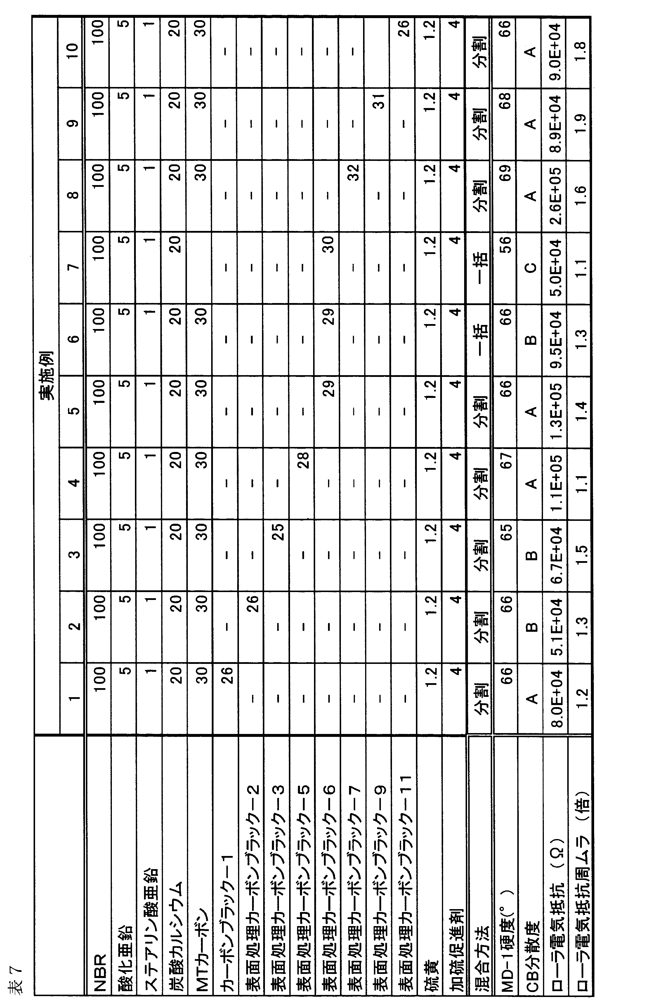
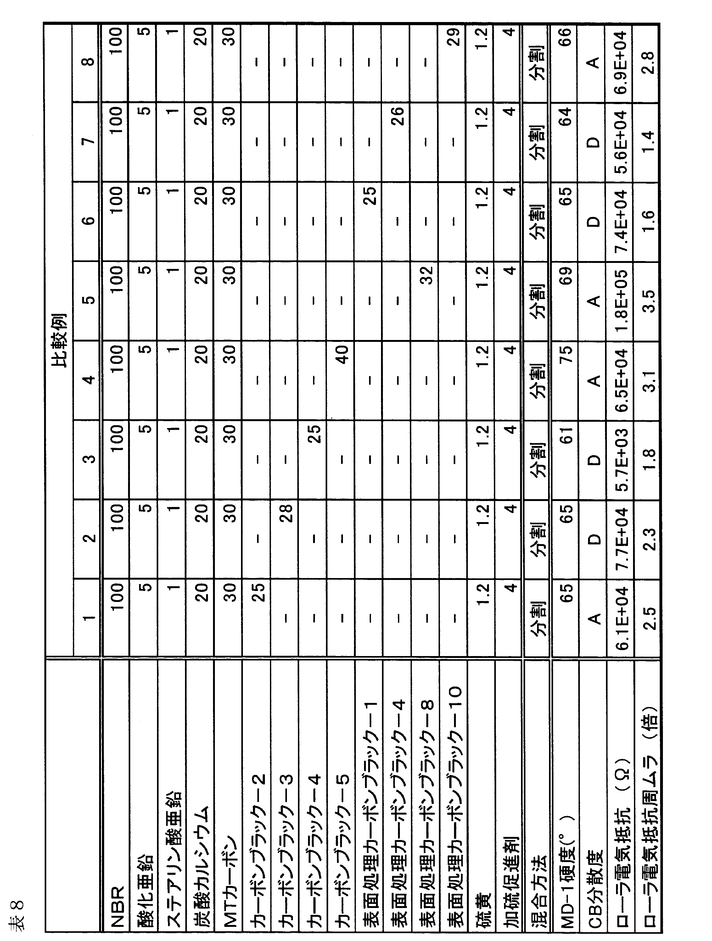
表6及び表8から明らかなように、比較例1に用いたカーボンブラック2、及び比較例8に用いた表面処理カーボンブラック10は、いずれもカーボン表面官能基分析において、COおよびCO2の発生量合計が0.80質量%以上であった。このため、比較例1及び8で作製した帯電ローラにおける電気抵抗の周方向ムラは、2.0倍以上と大きかった。
比較例2に用いたカーボンブラック3は、カーボン表面官能基分析において、SO2発生量が0.05質量%未満であるため、比較例2で作製した帯電ローラにおける弾性層中のカーボンブラックの分散度評価がDランクとなった。
比較例3に用いたカーボンブラック4は、平均一次粒子径が20nm未満であるため、弾性層中のカーボンブラックの分散度評価がDランクとなった。比較例4に用いたカーボンブラック5は、平均一次粒子径が30nmを超えており、電気抵抗の調整に比較的多量のカーボンブラックを配合することが望まれ、硬度が75°以上と硬くなった。また、帯電ローラの電気抵抗の周方向ムラも2倍以上となった。
比較例5に用いた表面処理カーボンブラック-8は、DBP吸油量が70ml/100gを超えているため、帯電ローラにおける電気抵抗の周方向ムラが、3.0倍以上と大きかった。
比較例6に用いた表面処理カーボンブラック-1及び比較例7に用いた表面処理カーボンブラック-4は、いずれもカーボン表面官能基の量が少なく、弾性層中のカーボンブラックの分散度評価がDランクとなった。
これに対して、表7から明らかなように、第1のCBの要件を満たすカーボンブラックを用いた実施例1~10は、MD-1硬度が75°未満であり、ローラ電気抵抗の周方向ムラも2倍未満となった。
この出願は2012年9月21日に出願された日本国特許出願第2012-207958からの優先権を主張するものであり、その内容を引用してこの出願の一部とするものである。
10 帯電ローラ
11 芯金
12 弾性層
13 表面層
21 電子写真感光体
21a 感光層
21b 支持体
21c 軸
22、23 電源
23a 摺擦電源
24 露光手段
25 現像手段
26 転写手段
27 転写材
28 クリーニング手段
31 外側ダイ
32 内側ダイ
41 アルミドラム
42 外部電源
43 基準抵抗
50 押出機
51 シリンダー
52 スクリュー
53 クロスヘッド
54 材料投入口
55 ベント口
56 ダイス
57 スクリューダム部
11 芯金
12 弾性層
13 表面層
21 電子写真感光体
21a 感光層
21b 支持体
21c 軸
22、23 電源
23a 摺擦電源
24 露光手段
25 現像手段
26 転写手段
27 転写材
28 クリーニング手段
31 外側ダイ
32 内側ダイ
41 アルミドラム
42 外部電源
43 基準抵抗
50 押出機
51 シリンダー
52 スクリュー
53 クロスヘッド
54 材料投入口
55 ベント口
56 ダイス
57 スクリューダム部
Claims (7)
- 導電性支持体と、導電性の弾性層とを有する導電性部材であって、
該弾性層は、電子導電剤とバインダーポリマーとを含む混合物または該混合物の硬化物であり、
該電子導電剤が下記特性(i)~(iii)を有するカーボンブラックを含むことを特徴とする導電性部材:
(i)平均一次粒子径が20nm以上30nm以下;
(ii)DBP吸油量が40ml/100g以上70ml/100g以下;
(iii)加熱ガス発生分析により発生するCOおよびCO2の総量が、該カーボンブラック基準で、0.30質量%以上0.80質量%以下、SO2の量が、該カーボンブラック基準で、0.05質量%以上。 - 前記加熱ガス発生分析により発生するSO2の量が、前記カーボンブラック基準で、0.15質量%以下である請求項1に記載の導電性部材。
- 前記カーボンブラックの前記弾性層中における含有量が、前記バインダーポリマーまたはその硬化物100質量部に対して5質量部以上、60質量部以下である請求項1または2に記載の導電性部材。
- 前記電子導電剤が、下記特性(iv)及び(v)を有するカーボンブラックを更に含む請求項1~3のいずれか一項に記載の導電性部材:
(iv)平均一次粒子径が、100nm以上300nm以下;
(v)DBP吸油量が20ml/100g以上50ml/100g以下。 - 前記バインダーポリマーがゴムを含む請求項1~4のいずれか一項に記載の導電性部材。
- 電子写真装置の本体に着脱可能に構成されたプロセスカートリッジであって、
帯電部材と該帯電部材によって帯電可能に配置されてなる電子写真感光体とを有しており、
該帯電部材が、請求項1~5のいずれか一項に記載の導電性部材であることを特徴とするプロセスカートリッジ。 - 帯電部材と、該帯電部材によって帯電可能に配置されてなる電子写真感光体とを有している電子写真装置であって、
該帯電部材が、請求項1~5のいずれか一項に記載の導電性部材であることを特徴とする電子写真装置。
Priority Applications (3)
| Application Number | Priority Date | Filing Date | Title |
|---|---|---|---|
| EP12885011.2A EP2899594B1 (en) | 2012-09-21 | 2012-10-18 | Conductive member, electrophotographic apparatus, and process cartridge |
| CN201280075943.XA CN104662482B (zh) | 2012-09-21 | 2012-10-18 | 导电性构件、电子照相设备和处理盒 |
| US13/843,892 US8622881B1 (en) | 2012-09-21 | 2013-03-15 | Conductive member, electrophotographic apparatus, and process cartridge |
Applications Claiming Priority (2)
| Application Number | Priority Date | Filing Date | Title |
|---|---|---|---|
| JP2012207958A JP5220222B1 (ja) | 2012-09-21 | 2012-09-21 | 導電性部材 |
| JP2012-207958 | 2012-09-21 |
Related Child Applications (1)
| Application Number | Title | Priority Date | Filing Date |
|---|---|---|---|
| US13/843,892 Continuation US8622881B1 (en) | 2012-09-21 | 2013-03-15 | Conductive member, electrophotographic apparatus, and process cartridge |
Publications (1)
| Publication Number | Publication Date |
|---|---|
| WO2014045330A1 true WO2014045330A1 (ja) | 2014-03-27 |
Family
ID=48778729
Family Applications (1)
| Application Number | Title | Priority Date | Filing Date |
|---|---|---|---|
| PCT/JP2012/006659 Ceased WO2014045330A1 (ja) | 2012-09-21 | 2012-10-18 | 導電性部材、電子写真装置およびプロセスカートリッジ |
Country Status (5)
| Country | Link |
|---|---|
| US (1) | US8622881B1 (ja) |
| EP (1) | EP2899594B1 (ja) |
| JP (1) | JP5220222B1 (ja) |
| CN (1) | CN104662482B (ja) |
| WO (1) | WO2014045330A1 (ja) |
Cited By (1)
| Publication number | Priority date | Publication date | Assignee | Title |
|---|---|---|---|---|
| CN113391531A (zh) * | 2020-03-13 | 2021-09-14 | 住友橡胶工业株式会社 | 电子照相用导电性辊 |
Families Citing this family (30)
| Publication number | Priority date | Publication date | Assignee | Title |
|---|---|---|---|---|
| JP3433537B2 (ja) | 1994-11-28 | 2003-08-04 | 浜松ホトニクス株式会社 | 半導体光電陰極およびこれを用いた半導体光電陰極装置 |
| JP3537515B2 (ja) | 1994-11-28 | 2004-06-14 | 浜松ホトニクス株式会社 | 半導体光電陰極およびこれを用いた半導体光電陰極装置 |
| JP3433538B2 (ja) | 1994-11-28 | 2003-08-04 | 浜松ホトニクス株式会社 | 半導体光電陰極およびこれを用いた半導体光電陰極装置 |
| JP6056684B2 (ja) * | 2013-07-02 | 2017-01-11 | 富士ゼロックス株式会社 | 帯電部材の製造方法 |
| KR102016204B1 (ko) * | 2015-10-08 | 2019-08-29 | 캐논 가부시끼가이샤 | 전자사진용 도전성 부재, 그의 제조 방법, 프로세스 카트리지 및 전자사진 장치 |
| US9910379B2 (en) | 2015-10-26 | 2018-03-06 | Canon Kabushiki Kaisha | Charging member with concave portions containing insulating particles and electrophotographic apparatus |
| US9904199B2 (en) | 2015-10-26 | 2018-02-27 | Canon Kabushiki Kaisha | Charging member having outer surface with concave portions bearing exposed elastic particles, and electrophotographic apparatus |
| US10317811B2 (en) | 2016-10-07 | 2019-06-11 | Canon Kabushiki Kaisha | Charging member, method for producing same, process cartridge and electrophotographic image forming apparatus |
| US10416588B2 (en) | 2016-10-31 | 2019-09-17 | Canon Kabushiki Kaisha | Charging member, process cartridge, electrophotographic image forming apparatus, and method for manufacturing charging member |
| JP7034815B2 (ja) | 2017-04-27 | 2022-03-14 | キヤノン株式会社 | 帯電部材、電子写真プロセスカートリッジ及び電子写真画像形成装置 |
| JP7046571B2 (ja) | 2017-11-24 | 2022-04-04 | キヤノン株式会社 | プロセスカートリッジ及び電子写真装置 |
| JP7187270B2 (ja) | 2017-11-24 | 2022-12-12 | キヤノン株式会社 | プロセスカートリッジ及び電子写真装置 |
| CN112020678B (zh) | 2018-04-18 | 2022-11-01 | 佳能株式会社 | 导电性构件、处理盒和电子照相图像形成设备 |
| WO2019203238A1 (ja) | 2018-04-18 | 2019-10-24 | キヤノン株式会社 | 導電性部材及びその製造方法、プロセスカートリッジ並びに電子写真画像形成装置 |
| CN111989622B (zh) | 2018-04-18 | 2022-11-11 | 佳能株式会社 | 显影构件、处理盒和电子照相设备 |
| WO2019203225A1 (ja) | 2018-04-18 | 2019-10-24 | キヤノン株式会社 | 導電性部材、プロセスカートリッジ及び電子写真画像形成装置 |
| WO2019203227A1 (ja) | 2018-04-18 | 2019-10-24 | キヤノン株式会社 | 導電性部材、プロセスカートリッジ、および画像形成装置 |
| US10558136B2 (en) | 2018-04-18 | 2020-02-11 | Canon Kabushiki Kaisha | Charging member, manufacturing method of charging member, electrophotographic apparatus, and process cartridge |
| CN112005173B (zh) | 2018-04-18 | 2023-03-24 | 佳能株式会社 | 导电性构件、处理盒和图像形成设备 |
| US10969709B2 (en) * | 2018-04-20 | 2021-04-06 | Canon Kabushiki Kaisha | Member for electrophotography, process cartridge and electrophotographic apparatus |
| CN112334840B (zh) * | 2018-07-30 | 2023-03-21 | 住友理工株式会社 | 电子照相设备用导电性辊 |
| US11169454B2 (en) | 2019-03-29 | 2021-11-09 | Canon Kabushiki Kaisha | Electrophotographic electro-conductive member, process cartridge, and electrophotographic image forming apparatus |
| CN114556230B (zh) | 2019-10-18 | 2024-03-08 | 佳能株式会社 | 电子照相用导电性构件、处理盒和电子照相图像形成装置 |
| CN114556232B (zh) | 2019-10-18 | 2023-06-27 | 佳能株式会社 | 导电性构件、处理盒和电子照相图像形成设备 |
| JP7669134B2 (ja) | 2019-10-18 | 2025-04-28 | キヤノン株式会社 | 導電性部材、プロセスカートリッジ並びに電子写真画像形成装置 |
| CN114556231B (zh) | 2019-10-18 | 2023-06-27 | 佳能株式会社 | 导电性构件、其制造方法、处理盒以及电子照相图像形成设备 |
| WO2021075441A1 (ja) | 2019-10-18 | 2021-04-22 | キヤノン株式会社 | 導電性部材、プロセスカートリッジ及び電子写真画像形成装置 |
| JP2022168615A (ja) * | 2021-04-26 | 2022-11-08 | 住友ゴム工業株式会社 | 電子写真用導電性ローラ |
| US12498646B2 (en) | 2023-09-27 | 2025-12-16 | Canon Kabushiki Kaisha | Electrophotographic conductive member, process cartridge, and electrophotographic image forming apparatus |
| JP2025056886A (ja) | 2023-09-27 | 2025-04-09 | キヤノン株式会社 | 電子写真部材、プロセスカートリッジ、及び電子写真画像形成装置 |
Citations (4)
| Publication number | Priority date | Publication date | Assignee | Title |
|---|---|---|---|---|
| JPH1145013A (ja) | 1997-05-26 | 1999-02-16 | Bridgestone Corp | Oa機器用部材 |
| JP2006265379A (ja) * | 2005-03-24 | 2006-10-05 | Seiko Epson Corp | 水性インク組成物 |
| JP2008013704A (ja) * | 2006-07-07 | 2008-01-24 | Sumitomo Rubber Ind Ltd | ゴム組成物 |
| JP2008299120A (ja) * | 2007-05-31 | 2008-12-11 | Canon Inc | 帯電部材 |
Family Cites Families (22)
| Publication number | Priority date | Publication date | Assignee | Title |
|---|---|---|---|---|
| US5198685A (en) | 1990-08-01 | 1993-03-30 | Canon Kabushiki Kaisha | Photoelectric conversion apparatus with shock-absorbing layer |
| CN1492002A (zh) * | 1997-08-28 | 2004-04-28 | 三菱化学株式会社 | 炭黑及其制备方法 |
| JP2003113347A (ja) * | 2001-10-03 | 2003-04-18 | Bando Chem Ind Ltd | 導電性コーティング剤、電子写真装置用部材及び電子写真装置用中間転写体 |
| JP3880567B2 (ja) * | 2002-10-24 | 2007-02-14 | キヤノン株式会社 | 新規なポリヒドロキシアルカノエート共重合体 |
| US7486911B2 (en) | 2003-01-17 | 2009-02-03 | Canon Kabushiki Kaisha | Elastic member, process for manufacturing thereof and mass production process thereof, process cartridge, and electrophotographic apparatus |
| CN100436549C (zh) * | 2003-08-05 | 2008-11-26 | 三菱化学株式会社 | 炭黑 |
| JP4455454B2 (ja) | 2004-09-02 | 2010-04-21 | キヤノン株式会社 | 帯電部材、プロセスカートリッジおよび電子写真装置 |
| US7693457B2 (en) | 2004-12-28 | 2010-04-06 | Canon Kabushiki Kaisha | Charging member, process cartridge, and electrophotographic apparatus |
| JP4187754B2 (ja) * | 2005-05-09 | 2008-11-26 | キヤノン化成株式会社 | 転写ローラ及び画像形成装置 |
| JP4771909B2 (ja) * | 2006-10-31 | 2011-09-14 | 株式会社リコー | 電子写真感光体、それを用いた画像形成方法、画像形成装置及び画像形成装置用プロセスカートリッジ、及び電子写真感光体の製造方法 |
| JP5366425B2 (ja) * | 2007-04-20 | 2013-12-11 | キヤノン株式会社 | 現像ローラ、現像ローラの製造方法、プロセスカートリッジ及び画像形成装置 |
| WO2011045916A1 (ja) | 2009-10-15 | 2011-04-21 | キヤノン株式会社 | 帯電部材及び電子写真装置 |
| WO2011108669A1 (ja) * | 2010-03-03 | 2011-09-09 | クラレリビング株式会社 | 導電性マルチフィラメント糸及び導電性ブラシ |
| US8329080B2 (en) * | 2010-04-13 | 2012-12-11 | Ricoh Company, Ltd. | Conductive composition, electrophotographic belt, image forming apparatus, and method of manufacturing conductive composition |
| JP5875264B2 (ja) | 2010-07-13 | 2016-03-02 | キヤノン株式会社 | 帯電部材の製造方法 |
| EP2607960B1 (en) | 2010-08-20 | 2018-01-03 | Canon Kabushiki Kaisha | Charging member |
| JP4921607B2 (ja) | 2010-09-03 | 2012-04-25 | キヤノン株式会社 | 帯電部材およびその製造方法 |
| WO2012049814A1 (ja) | 2010-10-15 | 2012-04-19 | キヤノン株式会社 | 帯電部材 |
| JP4975184B2 (ja) | 2010-11-11 | 2012-07-11 | キヤノン株式会社 | 帯電部材 |
| WO2012098834A1 (ja) | 2011-01-21 | 2012-07-26 | キヤノン株式会社 | 導電性ゴム弾性体、帯電部材および電子写真装置 |
| WO2012137419A1 (ja) | 2011-04-05 | 2012-10-11 | キヤノン株式会社 | 電子写真用導電性部材、電子写真装置およびプロセスカートリッジ |
| WO2013001736A1 (ja) | 2011-06-30 | 2013-01-03 | キヤノン株式会社 | 帯電部材、帯電部材の製造方法および電子写真装置 |
-
2012
- 2012-09-21 JP JP2012207958A patent/JP5220222B1/ja active Active
- 2012-10-18 WO PCT/JP2012/006659 patent/WO2014045330A1/ja not_active Ceased
- 2012-10-18 EP EP12885011.2A patent/EP2899594B1/en active Active
- 2012-10-18 CN CN201280075943.XA patent/CN104662482B/zh active Active
-
2013
- 2013-03-15 US US13/843,892 patent/US8622881B1/en active Active
Patent Citations (4)
| Publication number | Priority date | Publication date | Assignee | Title |
|---|---|---|---|---|
| JPH1145013A (ja) | 1997-05-26 | 1999-02-16 | Bridgestone Corp | Oa機器用部材 |
| JP2006265379A (ja) * | 2005-03-24 | 2006-10-05 | Seiko Epson Corp | 水性インク組成物 |
| JP2008013704A (ja) * | 2006-07-07 | 2008-01-24 | Sumitomo Rubber Ind Ltd | ゴム組成物 |
| JP2008299120A (ja) * | 2007-05-31 | 2008-12-11 | Canon Inc | 帯電部材 |
Non-Patent Citations (1)
| Title |
|---|
| See also references of EP2899594A4 |
Cited By (2)
| Publication number | Priority date | Publication date | Assignee | Title |
|---|---|---|---|---|
| CN113391531A (zh) * | 2020-03-13 | 2021-09-14 | 住友橡胶工业株式会社 | 电子照相用导电性辊 |
| CN113391531B (zh) * | 2020-03-13 | 2025-10-31 | 住友橡胶工业株式会社 | 电子照相用导电性辊 |
Also Published As
| Publication number | Publication date |
|---|---|
| JP2014063024A (ja) | 2014-04-10 |
| CN104662482B (zh) | 2017-02-08 |
| EP2899594A1 (en) | 2015-07-29 |
| EP2899594B1 (en) | 2017-08-23 |
| JP5220222B1 (ja) | 2013-06-26 |
| EP2899594A4 (en) | 2016-05-11 |
| US8622881B1 (en) | 2014-01-07 |
| CN104662482A (zh) | 2015-05-27 |
Similar Documents
| Publication | Publication Date | Title |
|---|---|---|
| JP5220222B1 (ja) | 導電性部材 | |
| JP3639773B2 (ja) | 半導電性ゴム組成物、帯電部材、電子写真装置、プロセスカートリッジ | |
| CN110874034B (zh) | 显影辊、电子照相处理盒和电子照相图像形成设备 | |
| CN114556231B (zh) | 导电性构件、其制造方法、处理盒以及电子照相图像形成设备 | |
| JP4034595B2 (ja) | ゴムロール | |
| JP2004109688A (ja) | 帯電部材の再生方法、帯電部材、及び帯電部材の再生装置 | |
| JP7424139B2 (ja) | 帯電部材、帯電装置、プロセスカートリッジ、及び画像形成装置 | |
| JP2007292298A (ja) | 帯電部材の製造方法 | |
| JP2008299120A (ja) | 帯電部材 | |
| JP7046598B2 (ja) | 帯電部材の製造方法 | |
| JP2008299109A (ja) | 導電性ローラ、その製造方法、電子写真装置及びプロセスカートリッジ | |
| JP2007193110A (ja) | 導電性部材及びそれを有するプロセスカートリッジ、並びに、そのプロセスカートリッジを有する画像形成装置 | |
| JP5876684B2 (ja) | 帯電ローラ及び導電性ローラの製造方法 | |
| JP2002108062A (ja) | 帯電部材 | |
| JP4096526B2 (ja) | 中間転写体、中間転写体の製造方法、画像形成装置 | |
| JP2006251008A (ja) | 帯電部材、プロセスカートリッジ及び画像形成装置 | |
| JP4244740B2 (ja) | 帯電ロール及びそれを用いた画像形成装置 | |
| JP5230186B2 (ja) | 弾性部材及びその製造方法 | |
| JP5106009B2 (ja) | 電子写真装置用導電性部材 | |
| JP2020181006A (ja) | 帯電装置、プロセスカートリッジ及び画像形成装置 | |
| JP2005024830A (ja) | 帯電部材及びそれを有するカートリッジ、並びに、カートリッジを有する画像形成装置 | |
| JP5317510B2 (ja) | 帯電部材、電子写真画像形成装置 | |
| JP2004246036A (ja) | 導電性ローラー | |
| JP2007171826A (ja) | 電子写真装置用導電性部材 | |
| JP2009036853A (ja) | 導電性弾性ローラの製造方法 |
Legal Events
| Date | Code | Title | Description |
|---|---|---|---|
| 121 | Ep: the epo has been informed by wipo that ep was designated in this application |
Ref document number: 12885011 Country of ref document: EP Kind code of ref document: A1 |
|
| REEP | Request for entry into the european phase |
Ref document number: 2012885011 Country of ref document: EP |
|
| NENP | Non-entry into the national phase |
Ref country code: DE |