WO2014045747A1 - 電気モーターの冷却構造 - Google Patents
電気モーターの冷却構造 Download PDFInfo
- Publication number
- WO2014045747A1 WO2014045747A1 PCT/JP2013/071335 JP2013071335W WO2014045747A1 WO 2014045747 A1 WO2014045747 A1 WO 2014045747A1 JP 2013071335 W JP2013071335 W JP 2013071335W WO 2014045747 A1 WO2014045747 A1 WO 2014045747A1
- Authority
- WO
- WIPO (PCT)
- Prior art keywords
- power line
- motor
- electric motor
- cooling structure
- terminal block
- Prior art date
- Legal status (The legal status is an assumption and is not a legal conclusion. Google has not performed a legal analysis and makes no representation as to the accuracy of the status listed.)
- Ceased
Links
Images




Classifications
-
- H—ELECTRICITY
- H02—GENERATION; CONVERSION OR DISTRIBUTION OF ELECTRIC POWER
- H02K—DYNAMO-ELECTRIC MACHINES
- H02K9/00—Arrangements for cooling or ventilating
- H02K9/19—Arrangements for cooling or ventilating for machines with closed casing and closed-circuit cooling using a liquid cooling medium, e.g. oil
- H02K9/193—Arrangements for cooling or ventilating for machines with closed casing and closed-circuit cooling using a liquid cooling medium, e.g. oil with provision for replenishing the cooling medium; with means for preventing leakage of the cooling medium
-
- H—ELECTRICITY
- H02—GENERATION; CONVERSION OR DISTRIBUTION OF ELECTRIC POWER
- H02K—DYNAMO-ELECTRIC MACHINES
- H02K11/00—Structural association of dynamo-electric machines with electric components or with devices for shielding, monitoring or protection
- H02K11/30—Structural association with control circuits or drive circuits
- H02K11/33—Drive circuits, e.g. power electronics
-
- H—ELECTRICITY
- H02—GENERATION; CONVERSION OR DISTRIBUTION OF ELECTRIC POWER
- H02K—DYNAMO-ELECTRIC MACHINES
- H02K5/00—Casings; Enclosures; Supports
- H02K5/04—Casings or enclosures characterised by the shape, form or construction thereof
- H02K5/20—Casings or enclosures characterised by the shape, form or construction thereof with channels or ducts for flow of cooling medium
-
- H—ELECTRICITY
- H02—GENERATION; CONVERSION OR DISTRIBUTION OF ELECTRIC POWER
- H02K—DYNAMO-ELECTRIC MACHINES
- H02K5/00—Casings; Enclosures; Supports
- H02K5/04—Casings or enclosures characterised by the shape, form or construction thereof
- H02K5/20—Casings or enclosures characterised by the shape, form or construction thereof with channels or ducts for flow of cooling medium
- H02K5/203—Casings or enclosures characterised by the shape, form or construction thereof with channels or ducts for flow of cooling medium specially adapted for liquids, e.g. cooling jackets
-
- H—ELECTRICITY
- H02—GENERATION; CONVERSION OR DISTRIBUTION OF ELECTRIC POWER
- H02K—DYNAMO-ELECTRIC MACHINES
- H02K5/00—Casings; Enclosures; Supports
- H02K5/04—Casings or enclosures characterised by the shape, form or construction thereof
- H02K5/22—Auxiliary parts of casings not covered by groups H02K5/06-H02K5/20, e.g. shaped to form connection boxes or terminal boxes
- H02K5/225—Terminal boxes or connection arrangements
-
- H—ELECTRICITY
- H01—ELECTRIC ELEMENTS
- H01R—ELECTRICALLY-CONDUCTIVE CONNECTIONS; STRUCTURAL ASSOCIATIONS OF A PLURALITY OF MUTUALLY-INSULATED ELECTRICAL CONNECTING ELEMENTS; COUPLING DEVICES; CURRENT COLLECTORS
- H01R9/00—Structural associations of a plurality of mutually-insulated electrical connecting elements, e.g. terminal strips or terminal blocks; Terminals or binding posts mounted upon a base or in a case; Bases therefor
- H01R9/22—Bases, e.g. strip, block, panel
- H01R9/24—Terminal blocks
Definitions
- This invention relates to a cooling structure for an electric motor.
- a structure in which a motor control circuit (inverter) is integrated with an electric motor is known.
- the power line connecting the motor and the inverter is short, the heat of the motor coil is easily transmitted to the inverter through the power line. If the amount of heat transferred is large, the semiconductor element inside the inverter may break down.
- JP2010-268633A proposes a structure for cooling the power line. Specifically, a terminal block for connecting the inverter power line and the motor power line and a cooler with a built-in water channel are connected via an L-shaped heat transfer member. One flat plate portion (first flat plate portion) of the L-shaped heat transfer member is bonded and fixed to the cooler surface away from the water channel. A second flat plate portion orthogonal to the first flat plate portion is bonded and fixed to the terminal block. Then, the inverter power line is bolted to the terminal block with the second flat plate portion interposed therebetween.
- JP2010-268633A since the cooler and the terminal block are connected by an L-shaped heat transfer member, the tolerance of each part must be strictly controlled. Even if the tolerance is strictly controlled, there is a possibility that a gap may be formed between the cooler and the first flat plate portion or between the terminal block and the second flat plate portion due to variations in component accuracy. If there is a gap, the thermal resistance transmitted from the cooler surface to the terminal block will increase, the cooling performance of the power line connected to the terminal block will deteriorate, and the motor coil heat may be transmitted to the motor control circuit via the power line. .
- An object of the present invention is to provide a cooling structure for an electric motor in which heat of a motor coil is not easily transmitted to a motor control circuit via a power line even if the motor control circuit is integrated with the electric motor.
- One aspect of the cooling structure of the electric motor according to the present invention is a motor case in which a stator and a rotor are accommodated and a groove is formed in an end surface in the rotor axial direction, and a motor control circuit attached to the motor case. ,including.
- the groove further includes a terminal block for connecting the power line of the motor and the power line of the motor control circuit as well as making the groove a cooling water path through which the cooling water can flow.
- FIG. 1 is a perspective view showing main components of a cooling structure for an electric motor according to the present invention.
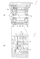
- FIG. 2 is a longitudinal sectional view showing main components of the cooling structure of the electric motor according to the present invention.
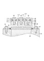
- FIG. 3 is an enlarged view of a transverse section in the vicinity of the terminal block.
- FIG. 4 is a view showing a second embodiment of the cooling structure of the electric motor according to the present invention.
- FIG. 5 is a view showing a third embodiment of the electric motor cooling structure according to the present invention.
- FIG. 6 is a view showing a fourth embodiment of the cooling structure of the electric motor according to the present invention.
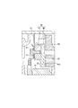
- FIG. 7 is a view showing a fifth embodiment of the electric motor cooling structure according to the present invention.
- FIG. 1 is a perspective view showing main components of a cooling structure for an electric motor according to the present invention.
- the electric motor cooling structure 1 mainly includes a stator 10, a motor case 20, an inverter 30, and a terminal block 40.
- the stator 10 is housed in the motor case 20 together with a rotor (not shown).
- Stator 10 includes a U-phase motor power line 11U, a V-phase motor power line 11V, and a W-phase motor power line 11W. These motor power lines extend toward the inverter 30. In FIG. 1, since the inverter 30 is disposed above the motor case 20, these motor power lines extend upward.
- the U-phase motor power line 11U is connected to the U-phase inverter power line 31U at the terminal block 40.
- the V-phase motor power line 11V is connected to the V-phase inverter power line 31V at the terminal block 40.
- W-phase motor power line 11W is connected to W-phase inverter power line 31W at terminal block 40.
- the motor case 20 houses the stator 10 and a rotor (not shown).
- the motor case 20 has a substantially cylindrical shape.
- a groove 22 opened in the end surface 21 in the rotation axis direction of the rotor is dug. Cooling water for cooling the electric motor flows through the groove 22.
- the groove 22 is formed to have a predetermined length in the circumferential direction of the motor case 20, but a hole penetrating the motor case 20 in the rotor axial direction is formed continuously to the groove 22. .
- the inverter 30 is a circuit that controls the motor.
- the inverter 30 converts DC power of a battery (not shown) into three-phase AC power and supplies it to the motor.
- regenerative power (three-phase AC power) generated by the rotational force of the rotor is converted to DC power and supplied to a battery (not shown).
- Inverter 30 includes a U-phase inverter power line 31U, a V-phase inverter power line 31V, and a W-phase inverter power line 31W. These inverter power lines extend toward the motor (stator 10). In FIG. 1, these inverter power lines extend downward.
- the terminal block 40 is attached to the end surface 21 of the motor case 20 with the seal member 50 interposed therebetween.
- the terminal block 40 is fastened to the motor case 20 with bolts 61 in the rotation axis direction of the rotor.
- the sealing member 50 has a shape surrounding the groove 22 that opens in the motor case 20.
- FIG. 2 is a longitudinal sectional view showing main components of the cooling structure of the electric motor according to the present invention
- FIG. 2 (A) is an overall view
- FIG. 2 (B) is an enlarged view of part B of FIG. 2 (A). .
- the electric motor cooling structure 1 mainly includes a stator 10, a rotor 100, a motor case 20, an inverter 30, and a terminal block 40. .
- the stator 10 and the rotor 100 are housed in the motor case 20.
- a front cover 25F and a rear cover 25R are attached to the front and rear of the motor case 20.
- the inverter 30 is disposed on the front cover 25F and the rear cover 25R.
- the terminal block 40 is attached so as to close the groove 22 of the motor case 20 with the seal member 50 interposed therebetween.
- the terminal block 40 includes a power line fixing part 41 and a terminal block body 42.
- a female screw is formed in the power line fixing portion 41, and a bolt 62 is fastened to the female screw.
- the bolt 62 fastens the motor power line 11 and the inverter power line 31 together.
- the bolt 62 is fastened with the inverter power line 31 overlaid on the terminal block 40 and the motor power line 11 overlaid thereon.
- the power line fixing portion 41 and the bolt 62 are manufactured from a metal such as carbon steel.
- the terminal block body 42 is made of, for example, resin and is electrically insulating.
- the terminal block body 42 is cast with a power line fixing portion 41. This terminal block body 42 closes the groove 22 of the motor case 20.
- FIG. 3 is an enlarged view of the cross section near the terminal block.
- the terminal block 40 includes a U-phase power line fixing portion 41U, a V-phase power line fixing portion 41V, a W-phase power line fixing portion 41W, and a terminal block body 42.
- the U-phase power line fixing portion 41U fastens the U-phase motor power line 11U and the U-phase inverter power line 31U together with the bolt 62.
- the V-phase power line fixing unit 41V fastens the V-phase motor power line 11V and the V-phase inverter power line 31V together with the bolt 62.
- W-phase power line fixing portion 41 ⁇ / b> W fastens W-phase motor power line 11 ⁇ / b> W and W-phase inverter power line 31 ⁇ / b> W together with bolt 62.
- the terminal block body 42 casts a U-phase power line fixing portion 41U, a V-phase power line fixing portion 41V, and a W-phase power line fixing portion 41W. Due to such a structure, the U-phase power line fixing part 41U, the V-phase power line fixing part 41V, and the W-phase power line fixing part 41W are electrically insulated from each other.
- a metal collar 43 is cast on the terminal block 40. The bolt 61 is inserted into the metal collar 43 and fastened to the motor case 20.
- a groove 22 that opens in the end surface 21 of the motor case 20 is formed, and the groove 22 is closed with a terminal block 40 that connects the motor power line 11 and the inverter power line 31, thereby cooling the cooling water channel. Formed. Since it did in this way, since the terminal block 40 (the motor power line 11 and the inverter power line 31) is directly cooled by the cooling water which flows through a cooling water channel, the heat of a motor coil is hard to be transmitted to the inside of an inverter.
- the inverter power line 31 is overlaid on the terminal block 40, and the bolt 62 is fastened with the motor power line 11 overlaid thereon. Because of such a structure, the inverter power line 31 is more easily cooled than the structure in which the motor power line 11 is overlaid on the terminal block 40 and the inverter power line 31 is overlaid thereon. Therefore, it is difficult for the heat of the motor coil to be transferred to the inside of the inverter.
- the terminal block and the cooler with a built-in water channel are connected via an L-shaped heat transfer member. If there is a gap, the thermal resistance transmitted from the cooler surface to the terminal block increases, and the cooling performance of the power line connected to the terminal block deteriorates.
- the motor power line 11 and the inverter power line 31 are fixed to the terminal block 40, the lower surface of the terminal block 40 and the opening of the water channel 22 are adjacent to each other, By fastening in the axial direction, the terminal block 40 and the periphery of the opening of the water channel 22 can be fastened in one direction.
- an L-shaped heat transfer member composed of two flat plate portions interposed between the cooler and the terminal block is not required, so that a gap generated due to component tolerance can be suppressed. . Therefore, it is possible to reduce the thermal resistance and improve the cooling performance of the power line connected to the terminal block.
- the terminal block is directly cooled by the cooling water without using a heat transfer member in the middle, a good cooling performance can be obtained.
- FIG. 4 is a view showing a second embodiment of the cooling structure for the electric motor according to the present invention, and is an enlarged view of a transverse section in the vicinity of the terminal block.
- the terminal block body 42 of the present embodiment includes a lid portion 421 and a cast-in portion 422.
- the lid 421 is made of metal.
- the lid portion 421 is disposed so as to close the groove 22 of the motor case 20.
- the upper part of the cover part 421 is formed so as to expand upward from the root, and the cast-in part 422 enters the wedge-shaped part.
- the casting part 422 casts the U-phase power line fixing part 41U, the V-phase power line fixing part 41V, the W-phase power line fixing part 41W, and the wedge part of the lid part 421.
- the cast-in part 422 is electrically insulating, and is made of, for example, resin.
- the cooling water channel is formed by the metal lid 421, and the cooling water does not hit the resin part (casting part 422), so that moisture absorption of the resin part (casting part 422) is avoided. Is done. Therefore, the terminal block 40 of this embodiment is excellent in strength and durability performance. That is, according to the present embodiment, it is possible to provide a terminal block with high insulation reliability even for long-term use.
- FIG. 5 is a view showing a third embodiment of the cooling structure of the electric motor according to the present invention, and is an enlarged view of a transverse section in the vicinity of the terminal block.
- the terminal block 40 of this embodiment includes an insulating member 43 sandwiched between the power line fixing part 41 and the lid part 421.
- the insulating member 43 is, for example, a resin thin plate.
- the power line fixing portion 41 and the lid portion 421 are used. There must be a certain amount of clearance between them. Further, in order to ensure the strength of the resin between the power line fixing portion 41 and the lid portion 421, it is necessary to provide a gap between the power line fixing portion 41 and the lid portion 421 to ensure the thickness of the resin.
- the insulating member 43 desirably has a higher thermal conductivity than the cast-in part 422. This is because if the thermal conductivity is high, the thermal resistance becomes small and it is easy to suppress the temperature rise of the power line.
- FIG. 6 is a view showing a fourth embodiment of the cooling structure of the electric motor according to the present invention, and is an enlarged view of a transverse section in the vicinity of the terminal block.
- the terminal block 40 of the fourth embodiment includes not only the U-phase power line fixing part 41U, the V-phase power line fixing part 41V and the W-phase power line fixing part 41W, but also a neutral point power line fixing part 41N.
- This configuration can also remove heat from the neutral point, which is the maximum heat generation point of the motor, so that the continuous output performance of the motor can be improved.
- FIG. 7 is a view showing a fifth embodiment of the cooling structure for the electric motor according to the present invention, and is an enlarged view of a longitudinal section in the vicinity of the terminal block.
- the terminal block 40 of this embodiment has fins 42a formed on the surface that closes the groove 22.
- the fins 42a are configured in this way, the contact area between the terminal block 40 and the cooling water increases, so that even better cooling performance can be obtained.
- the fin length (high) corresponding to the neutral power line fixing portion is higher than the fin length (height) corresponding to the three-phase power line fixing portion. It is better to increase the size. In this way, the neutral point heat, which is the maximum heat generation point of the motor, can be extracted more efficiently.
- the electric motor cooling structure (1) described above includes a motor case (20) in which a stator (10) and a rotor are accommodated, and a groove (22) is formed in an end surface in the rotor axial direction.
- the motor control circuit (30) attached to the case (20) and the groove (22) are closed to make the groove (22) a cooling water path through which cooling water can flow, and the power line (11) of the motor and the motor And a terminal block (40) for connecting the power line (31) of the control circuit (30).
- the terminal block 40 (the motor power line 11 and the inverter power line 31) is directly cooled by the cooling water flowing through the cooling water passage, so that the heat of the motor coil is hardly transmitted to the inside of the inverter.
- the present invention is not limited to such a structure. You may adhere
Landscapes
- Engineering & Computer Science (AREA)
- Power Engineering (AREA)
- Microelectronics & Electronic Packaging (AREA)
- Motor Or Generator Frames (AREA)
- Motor Or Generator Cooling System (AREA)
Abstract
Description
図1は、本発明による電気モーターの冷却構造の主要な部品を示す斜視図である。
図4は、本発明による電気モーターの冷却構造の第2実施形態を示す図であり、端子台付近の横断面の拡大図である。
図5は、本発明による電気モーターの冷却構造の第3実施形態を示す図であり、端子台付近の横断面の拡大図である。
図6は、本発明による電気モーターの冷却構造の第4実施形態を示す図であり、端子台付近の横断面の拡大図である。
図7は、本発明による電気モーターの冷却構造の第5実施形態を示す図であり、端子台付近の縦断面の拡大図である。
Claims (8)
- ステーター及びローターを収装するとともに、ローター軸方向の端面に開口する溝が形成されるモーターケースと、
前記モーターケースに取り付けられるモーター制御回路と、
前記溝を塞いで、その溝を冷却水が通流可能な冷却水路にするとともに、モーターの電力線及びモーター制御回路の電力線を接続する端子台と、
を含む電気モーターの冷却構造。 - 請求項1に記載の電気モーターの冷却構造において、
前記モーターケースの溝の開口の周囲に設けられたシール部材をさらに含み、
前記端子台は、前記シール部材を挟んで、ローター軸方向の締結部材によって前記モーターケースに固定される、
電気モーターの冷却構造。 - 請求項1又は請求項2に記載の電気モーターの冷却構造において、
前記端子台は、
前記溝を塞ぐ蓋部と、
モーターの電力線及びモーター制御回路の電力線を共締めするボルトが締結される雌ねじが形成された電力線固定部と、
前記蓋部及び電力線固定部を電気的に絶縁して一体化させる結合部と、を含む、
電気モーターの冷却構造。 - 請求項3に記載の電気モーターの冷却構造において、
前記端子台は、前記蓋部及び電力線固定部に挟まれる絶縁部材をさらに含む、
電気モーターの冷却構造。 - 請求項4に記載の電気モーターの冷却構造において、
前記絶縁部材は、前記結合部よりも熱伝導率が高い、
電気モーターの冷却構造。 - 請求項1から請求項5までのいずれか1項に記載の電気モーターの冷却構造において、
前記端子台は、前記冷却水路に臨むフィンを含む、
電気モーターの冷却構造。 - 請求項1から請求項6までのいずれか1項に記載の電気モーターの冷却構造において、
前記端子台は、さらにモーター中性点が接続される、
電気モーターの冷却構造。 - 請求項7に記載の電気モーターの冷却構造において、
前記端子台は、
モーターの電力線及びモーター制御回路の電力線が接続される箇所に対応して設けられて前記冷却水路に臨む第1のフィンと、
モーター中性点が接続される箇所に対応して設けられて前記冷却水路に臨み、前記第1のフィンよりも長さが長い第2のフィンと、を含む、
電気モーターの冷却構造。
Priority Applications (4)
| Application Number | Priority Date | Filing Date | Title |
|---|---|---|---|
| US14/429,968 US9502945B2 (en) | 2012-09-21 | 2013-08-07 | Cooling structure for electric motor |
| CN201380047771.XA CN104620478A (zh) | 2012-09-21 | 2013-08-07 | 电动机的冷却构造 |
| EP13840099.9A EP2899857B1 (en) | 2012-09-21 | 2013-08-07 | Cooling structure for electric motor |
| JP2014536669A JP5935894B2 (ja) | 2012-09-21 | 2013-08-07 | 電気モーターの冷却構造 |
Applications Claiming Priority (2)
| Application Number | Priority Date | Filing Date | Title |
|---|---|---|---|
| JP2012-208456 | 2012-09-21 | ||
| JP2012208456 | 2012-09-21 |
Publications (1)
| Publication Number | Publication Date |
|---|---|
| WO2014045747A1 true WO2014045747A1 (ja) | 2014-03-27 |
Family
ID=50341071
Family Applications (1)
| Application Number | Title | Priority Date | Filing Date |
|---|---|---|---|
| PCT/JP2013/071335 Ceased WO2014045747A1 (ja) | 2012-09-21 | 2013-08-07 | 電気モーターの冷却構造 |
Country Status (5)
| Country | Link |
|---|---|
| US (1) | US9502945B2 (ja) |
| EP (1) | EP2899857B1 (ja) |
| JP (1) | JP5935894B2 (ja) |
| CN (2) | CN104620478A (ja) |
| WO (1) | WO2014045747A1 (ja) |
Cited By (10)
| Publication number | Priority date | Publication date | Assignee | Title |
|---|---|---|---|---|
| JP2016096663A (ja) * | 2014-11-14 | 2016-05-26 | 日産自動車株式会社 | 回転電機システム |
| JP2017229174A (ja) * | 2016-06-23 | 2017-12-28 | 日産自動車株式会社 | 回転電機装置 |
| WO2019064584A1 (ja) * | 2017-09-29 | 2019-04-04 | 日産自動車株式会社 | 回転電機システム |
| WO2020021865A1 (ja) * | 2018-07-25 | 2020-01-30 | 株式会社デンソー | 回転電機ユニット |
| JP2020074675A (ja) * | 2020-01-09 | 2020-05-14 | 本田技研工業株式会社 | 一体型ユニット |
| JP2022160060A (ja) * | 2021-04-06 | 2022-10-19 | 三菱重工業株式会社 | 電気導体の冷却装置、電力変換装置及び回転電気機械 |
| WO2024009372A1 (ja) * | 2022-07-04 | 2024-01-11 | 日産自動車株式会社 | モータユニット |
| JPWO2024080075A1 (ja) * | 2022-10-12 | 2024-04-18 | ||
| JP2024077890A (ja) * | 2022-11-29 | 2024-06-10 | トヨタ自動車株式会社 | 端子台 |
| JP2024536130A (ja) * | 2021-09-28 | 2024-10-04 | シェフラー テクノロジーズ アー・ゲー ウント コー. カー・ゲー | ジャンクションボックスの中に位相バー冷却及びコンプライアント内部支持部を有するeモータ接続装置 |
Families Citing this family (14)
| Publication number | Priority date | Publication date | Assignee | Title |
|---|---|---|---|---|
| WO2015176634A1 (zh) * | 2014-05-17 | 2015-11-26 | 斯培兔 | 高耐候高密封不锈钢电机 |
| JP6406206B2 (ja) * | 2015-10-20 | 2018-10-17 | トヨタ自動車株式会社 | 回転電機の端子台接続構造 |
| KR102359705B1 (ko) * | 2016-07-20 | 2022-02-08 | 엘지마그나 이파워트레인 주식회사 | 전동기용 케이스 |
| CN109478821B (zh) * | 2016-07-20 | 2020-08-14 | Lg电子株式会社 | 用于电动机的壳体 |
| CN106505802A (zh) * | 2016-12-31 | 2017-03-15 | 合普动力股份有限公司 | 风冷一体化电机控制器 |
| CN107086743B (zh) * | 2017-05-22 | 2023-03-28 | 哈尔滨电气动力装备有限公司 | 油润滑的高温气冷堆核电厂主冷却风机电动机 |
| US11239723B2 (en) * | 2017-10-31 | 2022-02-01 | Deere & Company | Interconnection device |
| JP7135388B2 (ja) * | 2018-03-30 | 2022-09-13 | 日本電産トーソク株式会社 | 電動オイルポンプ |
| CN108808896B (zh) * | 2018-07-06 | 2024-07-05 | 金华市壹维科技有限公司 | 分段电枢电机定子及其制造工艺 |
| DE102020206124A1 (de) * | 2020-05-14 | 2021-11-18 | Volkswagen Aktiengesellschaft | Kontaktvorrichtung und Elektromotor |
| JP7310743B2 (ja) * | 2020-07-20 | 2023-07-19 | トヨタ自動車株式会社 | 電動駆動ユニット |
| DE102021202837A1 (de) * | 2021-03-23 | 2022-09-29 | Volkswagen Aktiengesellschaft | Antriebsanordnung für ein Kraftfahrzeug |
| DE102021211011A1 (de) * | 2021-09-30 | 2023-03-30 | Robert Bosch Gesellschaft mit beschränkter Haftung | Statoranordnung und Verfahren zum Montieren einer Statoranordnung |
| EP4391317A1 (en) * | 2022-12-19 | 2024-06-26 | Yamaha Hatsudoki Kabushiki Kaisha | Electric motor |
Citations (6)
| Publication number | Priority date | Publication date | Assignee | Title |
|---|---|---|---|---|
| JPH0914266A (ja) * | 1995-06-30 | 1997-01-14 | Koyo Seiko Co Ltd | 磁気軸受型スピンドル装置 |
| JP2006014452A (ja) * | 2004-06-24 | 2006-01-12 | Nissan Motor Co Ltd | 駆動装置 |
| JP2006014438A (ja) * | 2004-06-23 | 2006-01-12 | Honda Motor Co Ltd | モータ冷却システム |
| JP2010268633A (ja) | 2009-05-15 | 2010-11-25 | Honda Motor Co Ltd | モータユニット |
| JP2011182480A (ja) * | 2010-02-26 | 2011-09-15 | Hitachi Automotive Systems Ltd | 回転電機システム |
| JP2012244700A (ja) * | 2011-05-17 | 2012-12-10 | Toyota Motor Corp | 回転電機 |
Family Cites Families (8)
| Publication number | Priority date | Publication date | Assignee | Title |
|---|---|---|---|---|
| JPH0810974B2 (ja) * | 1988-04-25 | 1996-01-31 | 三菱電機株式会社 | 車両用交流発電機 |
| US5491370A (en) * | 1994-01-28 | 1996-02-13 | General Motors Corporation | Integrated AC machine |
| JP3486136B2 (ja) * | 1999-07-22 | 2004-01-13 | 三菱電機株式会社 | 車両用交流発電機 |
| JP4046283B2 (ja) * | 2003-07-01 | 2008-02-13 | 三菱電機株式会社 | 回転電機 |
| JP4756012B2 (ja) * | 2007-08-02 | 2011-08-24 | 本田技研工業株式会社 | 配電装置 |
| US8362665B2 (en) * | 2009-11-11 | 2013-01-29 | Remy Technologies, L.L.C. | Liquid cooled stator terminal block for an electric machine |
| JP5687027B2 (ja) * | 2010-10-27 | 2015-03-18 | 三菱重工業株式会社 | インバータ一体型電動圧縮機 |
| JP5672074B2 (ja) * | 2011-03-03 | 2015-02-18 | 住友電装株式会社 | 端子台 |
-
2013
- 2013-08-07 CN CN201380047771.XA patent/CN104620478A/zh active Pending
- 2013-08-07 EP EP13840099.9A patent/EP2899857B1/en active Active
- 2013-08-07 WO PCT/JP2013/071335 patent/WO2014045747A1/ja not_active Ceased
- 2013-08-07 JP JP2014536669A patent/JP5935894B2/ja active Active
- 2013-08-07 CN CN201811598113.0A patent/CN110048548B/zh active Active
- 2013-08-07 US US14/429,968 patent/US9502945B2/en active Active
Patent Citations (6)
| Publication number | Priority date | Publication date | Assignee | Title |
|---|---|---|---|---|
| JPH0914266A (ja) * | 1995-06-30 | 1997-01-14 | Koyo Seiko Co Ltd | 磁気軸受型スピンドル装置 |
| JP2006014438A (ja) * | 2004-06-23 | 2006-01-12 | Honda Motor Co Ltd | モータ冷却システム |
| JP2006014452A (ja) * | 2004-06-24 | 2006-01-12 | Nissan Motor Co Ltd | 駆動装置 |
| JP2010268633A (ja) | 2009-05-15 | 2010-11-25 | Honda Motor Co Ltd | モータユニット |
| JP2011182480A (ja) * | 2010-02-26 | 2011-09-15 | Hitachi Automotive Systems Ltd | 回転電機システム |
| JP2012244700A (ja) * | 2011-05-17 | 2012-12-10 | Toyota Motor Corp | 回転電機 |
Non-Patent Citations (1)
| Title |
|---|
| See also references of EP2899857A4 |
Cited By (16)
| Publication number | Priority date | Publication date | Assignee | Title |
|---|---|---|---|---|
| JP2016096663A (ja) * | 2014-11-14 | 2016-05-26 | 日産自動車株式会社 | 回転電機システム |
| JP2017229174A (ja) * | 2016-06-23 | 2017-12-28 | 日産自動車株式会社 | 回転電機装置 |
| WO2019064584A1 (ja) * | 2017-09-29 | 2019-04-04 | 日産自動車株式会社 | 回転電機システム |
| WO2020021865A1 (ja) * | 2018-07-25 | 2020-01-30 | 株式会社デンソー | 回転電機ユニット |
| JP2020074675A (ja) * | 2020-01-09 | 2020-05-14 | 本田技研工業株式会社 | 一体型ユニット |
| JP7657090B2 (ja) | 2021-04-06 | 2025-04-04 | 三菱重工業株式会社 | 電気導体の冷却装置、電力変換装置及び回転電気機械 |
| JP2022160060A (ja) * | 2021-04-06 | 2022-10-19 | 三菱重工業株式会社 | 電気導体の冷却装置、電力変換装置及び回転電気機械 |
| JP2024536130A (ja) * | 2021-09-28 | 2024-10-04 | シェフラー テクノロジーズ アー・ゲー ウント コー. カー・ゲー | ジャンクションボックスの中に位相バー冷却及びコンプライアント内部支持部を有するeモータ接続装置 |
| JP7714790B2 (ja) | 2021-09-28 | 2025-07-29 | シェフラー テクノロジーズ アー・ゲー ウント コー. カー・ゲー | ジャンクションボックスの中に位相バー冷却及びコンプライアント内部支持部を有するeモータ接続装置 |
| WO2024009372A1 (ja) * | 2022-07-04 | 2024-01-11 | 日産自動車株式会社 | モータユニット |
| JPWO2024009372A1 (ja) * | 2022-07-04 | 2024-01-11 | ||
| JP7823746B2 (ja) | 2022-07-04 | 2026-03-04 | 日産自動車株式会社 | モータユニット |
| JPWO2024080075A1 (ja) * | 2022-10-12 | 2024-04-18 | ||
| WO2024080075A1 (ja) * | 2022-10-12 | 2024-04-18 | ジヤトコ株式会社 | ユニット |
| JP7825062B2 (ja) | 2022-10-12 | 2026-03-05 | ジヤトコ株式会社 | ユニット |
| JP2024077890A (ja) * | 2022-11-29 | 2024-06-10 | トヨタ自動車株式会社 | 端子台 |
Also Published As
| Publication number | Publication date |
|---|---|
| CN110048548A (zh) | 2019-07-23 |
| CN104620478A (zh) | 2015-05-13 |
| JP5935894B2 (ja) | 2016-06-15 |
| US9502945B2 (en) | 2016-11-22 |
| EP2899857A4 (en) | 2016-03-16 |
| EP2899857A1 (en) | 2015-07-29 |
| EP2899857B1 (en) | 2017-06-28 |
| US20150244242A1 (en) | 2015-08-27 |
| CN110048548B (zh) | 2022-02-18 |
| JPWO2014045747A1 (ja) | 2016-08-18 |
Similar Documents
| Publication | Publication Date | Title |
|---|---|---|
| JP5935894B2 (ja) | 電気モーターの冷却構造 | |
| JP4657329B2 (ja) | 電力変換装置および電動車両 | |
| JP5911191B2 (ja) | 電気的なターボチャージャ | |
| JP5638094B2 (ja) | 電力制御装置の搭載構造 | |
| JP6295726B2 (ja) | 電動機 | |
| JP5931562B2 (ja) | 電動過給機 | |
| CN107276266A (zh) | 一种双向冷却油冷电机 | |
| CN102064628A (zh) | 用于电机的液冷式定子接线板 | |
| CN114079353B (zh) | 具有电动机器和逆变器的动力传动系、机动车辆 | |
| CN108886301A (zh) | 具有冷却装置的电机 | |
| CN107276275B (zh) | 一种轴向冷却电机 | |
| CN108336848A (zh) | 用于密封电力驱动器的定子的多个凹槽的设备 | |
| JP5178455B2 (ja) | 電力変換装置 | |
| JP5208577B2 (ja) | モータユニット | |
| CN103081304A (zh) | 用于容纳电驱动装置的壳体 | |
| US20150229186A1 (en) | Axial induction machine | |
| JP5240131B2 (ja) | 電動機の冷却構造 | |
| CN113661638A (zh) | 在壳体中支撑转矩的电动机器 | |
| JP5404836B2 (ja) | 電力変換装置 | |
| JP6289753B2 (ja) | 電力変換装置の筐体および樹脂キャップ | |
| JP2010213447A (ja) | 機電一体型駆動装置 | |
| JP2007037396A (ja) | 自動車トランスミッション用電機機械及び電機機械冷却装置 | |
| JP6733405B2 (ja) | 電動車両の冷却構造 | |
| JP2004088983A (ja) | インバータ搭載型回転電機及び回路装置 | |
| JP7371705B2 (ja) | 回転機 |
Legal Events
| Date | Code | Title | Description |
|---|---|---|---|
| 121 | Ep: the epo has been informed by wipo that ep was designated in this application |
Ref document number: 13840099 Country of ref document: EP Kind code of ref document: A1 |
|
| ENP | Entry into the national phase |
Ref document number: 2014536669 Country of ref document: JP Kind code of ref document: A |
|
| WWE | Wipo information: entry into national phase |
Ref document number: 14429968 Country of ref document: US |
|
| NENP | Non-entry into the national phase |
Ref country code: DE |
|
| REEP | Request for entry into the european phase |
Ref document number: 2013840099 Country of ref document: EP |
|
| WWE | Wipo information: entry into national phase |
Ref document number: 2013840099 Country of ref document: EP |