WO2014046147A1 - 蒸気供給システム及びこれを備えたco2回収設備 - Google Patents
蒸気供給システム及びこれを備えたco2回収設備 Download PDFInfo
- Publication number
- WO2014046147A1 WO2014046147A1 PCT/JP2013/075198 JP2013075198W WO2014046147A1 WO 2014046147 A1 WO2014046147 A1 WO 2014046147A1 JP 2013075198 W JP2013075198 W JP 2013075198W WO 2014046147 A1 WO2014046147 A1 WO 2014046147A1
- Authority
- WO
- WIPO (PCT)
- Prior art keywords
- condensed water
- steam
- water drum
- reboiler
- pressure
- Prior art date
- Legal status (The legal status is an assumption and is not a legal conclusion. Google has not performed a legal analysis and makes no representation as to the accuracy of the status listed.)
- Ceased
Links
Images


Classifications
-
- B—PERFORMING OPERATIONS; TRANSPORTING
- B01—PHYSICAL OR CHEMICAL PROCESSES OR APPARATUS IN GENERAL
- B01D—SEPARATION
- B01D53/00—Separation of gases or vapours; Recovering vapours of volatile solvents from gases; Chemical or biological purification of waste gases, e.g. engine exhaust gases, smoke, fumes, flue gases, aerosols
- B01D53/14—Separation of gases or vapours; Recovering vapours of volatile solvents from gases; Chemical or biological purification of waste gases, e.g. engine exhaust gases, smoke, fumes, flue gases, aerosols by absorption
- B01D53/1425—Regeneration of liquid absorbents
-
- B—PERFORMING OPERATIONS; TRANSPORTING
- B01—PHYSICAL OR CHEMICAL PROCESSES OR APPARATUS IN GENERAL
- B01D—SEPARATION
- B01D53/00—Separation of gases or vapours; Recovering vapours of volatile solvents from gases; Chemical or biological purification of waste gases, e.g. engine exhaust gases, smoke, fumes, flue gases, aerosols
- B01D53/14—Separation of gases or vapours; Recovering vapours of volatile solvents from gases; Chemical or biological purification of waste gases, e.g. engine exhaust gases, smoke, fumes, flue gases, aerosols by absorption
- B01D53/1412—Controlling the absorption process
-
- B—PERFORMING OPERATIONS; TRANSPORTING
- B01—PHYSICAL OR CHEMICAL PROCESSES OR APPARATUS IN GENERAL
- B01D—SEPARATION
- B01D53/00—Separation of gases or vapours; Recovering vapours of volatile solvents from gases; Chemical or biological purification of waste gases, e.g. engine exhaust gases, smoke, fumes, flue gases, aerosols
- B01D53/14—Separation of gases or vapours; Recovering vapours of volatile solvents from gases; Chemical or biological purification of waste gases, e.g. engine exhaust gases, smoke, fumes, flue gases, aerosols by absorption
- B01D53/1456—Removing acid components
- B01D53/1475—Removing carbon dioxide
-
- B—PERFORMING OPERATIONS; TRANSPORTING
- B01—PHYSICAL OR CHEMICAL PROCESSES OR APPARATUS IN GENERAL
- B01D—SEPARATION
- B01D53/00—Separation of gases or vapours; Recovering vapours of volatile solvents from gases; Chemical or biological purification of waste gases, e.g. engine exhaust gases, smoke, fumes, flue gases, aerosols
- B01D53/34—Chemical or biological purification of waste gases
- B01D53/46—Removing components of defined structure
- B01D53/62—Carbon oxides
-
- B—PERFORMING OPERATIONS; TRANSPORTING
- B01—PHYSICAL OR CHEMICAL PROCESSES OR APPARATUS IN GENERAL
- B01D—SEPARATION
- B01D53/00—Separation of gases or vapours; Recovering vapours of volatile solvents from gases; Chemical or biological purification of waste gases, e.g. engine exhaust gases, smoke, fumes, flue gases, aerosols
- B01D53/34—Chemical or biological purification of waste gases
- B01D53/74—General processes for purification of waste gases; Apparatus or devices specially adapted therefor
- B01D53/77—Liquid phase processes
- B01D53/78—Liquid phase processes with gas-liquid contact
-
- F—MECHANICAL ENGINEERING; LIGHTING; HEATING; WEAPONS; BLASTING
- F22—STEAM GENERATION
- F22B—METHODS OF STEAM GENERATION; STEAM BOILERS
- F22B37/00—Component parts or details of steam boilers
- F22B37/008—Adaptations for flue-gas purification in steam generators
-
- F—MECHANICAL ENGINEERING; LIGHTING; HEATING; WEAPONS; BLASTING
- F23—COMBUSTION APPARATUS; COMBUSTION PROCESSES
- F23J—REMOVAL OR TREATMENT OF COMBUSTION PRODUCTS OR COMBUSTION RESIDUES; FLUES
- F23J15/00—Arrangements of devices for treating smoke or fumes
- F23J15/02—Arrangements of devices for treating smoke or fumes of purifiers, e.g. for removing noxious material
-
- B—PERFORMING OPERATIONS; TRANSPORTING
- B01—PHYSICAL OR CHEMICAL PROCESSES OR APPARATUS IN GENERAL
- B01D—SEPARATION
- B01D2252/00—Absorbents, i.e. solvents and liquid materials for gas absorption
- B01D2252/20—Organic absorbents
- B01D2252/204—Amines
-
- B—PERFORMING OPERATIONS; TRANSPORTING
- B01—PHYSICAL OR CHEMICAL PROCESSES OR APPARATUS IN GENERAL
- B01D—SEPARATION
- B01D2252/00—Absorbents, i.e. solvents and liquid materials for gas absorption
- B01D2252/20—Organic absorbents
- B01D2252/204—Amines
- B01D2252/20478—Alkanolamines
-
- B—PERFORMING OPERATIONS; TRANSPORTING
- B01—PHYSICAL OR CHEMICAL PROCESSES OR APPARATUS IN GENERAL
- B01D—SEPARATION
- B01D2257/00—Components to be removed
- B01D2257/50—Carbon oxides
- B01D2257/504—Carbon dioxide
-
- B—PERFORMING OPERATIONS; TRANSPORTING
- B01—PHYSICAL OR CHEMICAL PROCESSES OR APPARATUS IN GENERAL
- B01D—SEPARATION
- B01D2258/00—Sources of waste gases
- B01D2258/02—Other waste gases
- B01D2258/0283—Flue gases
-
- B—PERFORMING OPERATIONS; TRANSPORTING
- B01—PHYSICAL OR CHEMICAL PROCESSES OR APPARATUS IN GENERAL
- B01D—SEPARATION
- B01D3/00—Distillation or related exchange processes in which liquids are contacted with gaseous media, e.g. stripping
- B01D3/14—Fractional distillation or use of a fractionation or rectification column
- B01D3/32—Other features of fractionating columns ; Constructional details of fractionating columns not provided for in groups B01D3/16 - B01D3/30
- B01D3/322—Reboiler specifications
-
- F—MECHANICAL ENGINEERING; LIGHTING; HEATING; WEAPONS; BLASTING
- F23—COMBUSTION APPARATUS; COMBUSTION PROCESSES
- F23J—REMOVAL OR TREATMENT OF COMBUSTION PRODUCTS OR COMBUSTION RESIDUES; FLUES
- F23J2215/00—Preventing emissions
- F23J2215/50—Carbon dioxide
-
- F—MECHANICAL ENGINEERING; LIGHTING; HEATING; WEAPONS; BLASTING
- F23—COMBUSTION APPARATUS; COMBUSTION PROCESSES
- F23J—REMOVAL OR TREATMENT OF COMBUSTION PRODUCTS OR COMBUSTION RESIDUES; FLUES
- F23J2219/00—Treatment devices
- F23J2219/40—Sorption with wet devices, e.g. scrubbers
-
- Y—GENERAL TAGGING OF NEW TECHNOLOGICAL DEVELOPMENTS; GENERAL TAGGING OF CROSS-SECTIONAL TECHNOLOGIES SPANNING OVER SEVERAL SECTIONS OF THE IPC; TECHNICAL SUBJECTS COVERED BY FORMER USPC CROSS-REFERENCE ART COLLECTIONS [XRACs] AND DIGESTS
- Y02—TECHNOLOGIES OR APPLICATIONS FOR MITIGATION OR ADAPTATION AGAINST CLIMATE CHANGE
- Y02A—TECHNOLOGIES FOR ADAPTATION TO CLIMATE CHANGE
- Y02A50/00—TECHNOLOGIES FOR ADAPTATION TO CLIMATE CHANGE in human health protection, e.g. against extreme weather
- Y02A50/20—Air quality improvement or preservation, e.g. vehicle emission control or emission reduction by using catalytic converters
-
- Y—GENERAL TAGGING OF NEW TECHNOLOGICAL DEVELOPMENTS; GENERAL TAGGING OF CROSS-SECTIONAL TECHNOLOGIES SPANNING OVER SEVERAL SECTIONS OF THE IPC; TECHNICAL SUBJECTS COVERED BY FORMER USPC CROSS-REFERENCE ART COLLECTIONS [XRACs] AND DIGESTS
- Y02—TECHNOLOGIES OR APPLICATIONS FOR MITIGATION OR ADAPTATION AGAINST CLIMATE CHANGE
- Y02C—CAPTURE, STORAGE, SEQUESTRATION OR DISPOSAL OF GREENHOUSE GASES [GHG]
- Y02C20/00—Capture or disposal of greenhouse gases
- Y02C20/40—Capture or disposal of greenhouse gases of CO2
-
- Y—GENERAL TAGGING OF NEW TECHNOLOGICAL DEVELOPMENTS; GENERAL TAGGING OF CROSS-SECTIONAL TECHNOLOGIES SPANNING OVER SEVERAL SECTIONS OF THE IPC; TECHNICAL SUBJECTS COVERED BY FORMER USPC CROSS-REFERENCE ART COLLECTIONS [XRACs] AND DIGESTS
- Y02—TECHNOLOGIES OR APPLICATIONS FOR MITIGATION OR ADAPTATION AGAINST CLIMATE CHANGE
- Y02E—REDUCTION OF GREENHOUSE GAS [GHG] EMISSIONS, RELATED TO ENERGY GENERATION, TRANSMISSION OR DISTRIBUTION
- Y02E20/00—Combustion technologies with mitigation potential
- Y02E20/32—Direct CO2 mitigation
Definitions
- the present invention relates to a steam supply system suitable for use in, for example, a CO 2 recovery facility in exhaust gas discharged from an industrial facility, and a CO 2 recovery facility including the same.
- CO 2 carbon dioxide
- Targeting industrial facilities for thermal power plants and the like which use a large amount of fossil fuels by contacting the flue gas of a boiler for example, an amine-based CO 2 absorbing solution, removing the CO 2 in the combustion exhaust gas, and a method of recovering, recovered A method for storing CO 2 without releasing it to the atmosphere is known.
- Patent Document 1 discloses that in a regeneration tower, a MEA (monoethanolamine) aqueous solution is regenerated by heating with a regeneration heater (reboiler), cooled by a heat exchanger, and returned to the de-CO 2 tower.
- MEA monoethanolamine
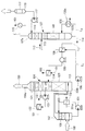
- FIG. 5 shows a schematic configuration showing a reference example of the steam supply system.
- Absorbing solution regeneration tower (not shown) (not shown) includes a circulation path L 4 for circulating outside the tower, re the steam supplied to the heat transfer tubes 130a of the reboiler 130 is attached to the bottom of the regenerator It is heated.
- a steam supply pipe 2 is connected to the reboiler 130, and steam is supplied to the heat transfer pipe 130a in the reboiler.
- the steam that has given heat to the absorption liquid by the heat transfer tube 130a is sent to the condensed water drum 5 and is gas-liquid separated in the condensing drum.
- the condensed water 6 flows from the bottom of the condensed water drum 5 through the drain extraction pipe 7 and is fed by the pump 8 through the steam drain pipe 9.
- the internal pressure of the condensed water drum has a small pressure difference in the heat transfer tube provided in the reboiler. This makes it difficult for the condensed water in the heat transfer tube provided in the reboiler to flow to the condensing drum, and the performance of the reboiler and the liquid level of the condensing water drum are unstable.
- the present invention has been made in view of such circumstances, and steam that can reheat the CO 2 absorbent without degrading the performance of the reboiler by appropriately controlling the internal pressure of the condensed water drum.
- the purpose is to provide a supply system.
- the steam supply system of the present invention and the CO 2 recovery facility equipped with the same employ the following means.
- the reboiler includes a heat transfer tube to which steam for heating is supplied, and a condensate water drum that collects steam condensate led from the heat transfer tube as a steam drain. Is provided with a pressure reducing means for lowering the pressure in the condensed water drum.
- pressure reducing means for reducing the pressure in the condensate water drum is provided.
- This pressure reducing means causes a pressure difference between the reboiler and the condensed water drum, and the condensed water easily flows from the high pressure side reboiler to the low pressure side condensed water drum.
- the performance of a reboiler and the liquid level of a condensed water drum can be stabilized. Since the performance of the reboiler is stabilized, heat can be stably given to the CO 2 absorbing liquid circulating in the regeneration tower. Thus, it is possible to reliably separate the CO 2 in CO 2 absorbing solution in the.
- the pressure reducing means is a cooling means for cooling the condensed water in the condensed water drum.
- a cooling means for cooling the condensed water in the condensed water drum is provided.
- this cooling means for example, a part of the condensed water extracted from the condensed water drum is cooled and returned to the condensed water drum again. Thereby, the temperature in the condensed water drum is cooled, and the pressure in the condensed water drum can be lowered.
- the cooling means is branched from a steam drain pipe for discharging the steam drain from the condensed water drum, and returns the steam drain to the condensed water drum.
- the steam drain flows through a drain circulation path branched from a steam drain pipe for discharging the steam drain from the condensed water drum, and is returned to the condensed water drum through a cooler.
- a drain circulation path branched from a steam drain pipe for discharging the steam drain from the condensed water drum, and is returned to the condensed water drum through a cooler.
- the cooling means includes a cooler provided in a steam drain pipe for discharging the steam drain from the condensed water drum, and a downstream side of the cooler.
- a steam drain circuit that is branched and returns the steam drain to the condensing drum.
- a steam drain circuit that branches off from the downstream side of the cooler and returns the steam drain to the condensate water drum is provided. Thereby, it is not necessary to provide a cooler in the circulation path.
- the cooling means includes a cooler provided in a reboiler outlet pipe connecting the reboiler and the condensed water drum.
- a cooler provided in a reboiler outlet pipe connecting the reboiler and the condensed water drum is provided.
- the temperature of the steam drain collected by the condensed water drum can be lowered. Since the steam drain cooled by the cooler is supplied to the condensate water drum, the saturation temperature and the saturation pressure can be lowered by cooling the condensate water drum. Therefore, the internal pressure of the condensed water drum can be lowered.
- the decompression means includes a vent pipe for discharging the gas phase in the condensed water drum.
- vent pipe in the condensate water drum, for example, when the internal pressure of the condensate water drum exceeds a certain value, the vent pipe can be opened to discharge the gas phase in the condensate water drum to lower the internal pressure. it can.
- a pressure measuring unit for obtaining a differential pressure between the internal pressure of the condensed water drum and the steam pressure supplied to the reboiler, and the pressure measuring unit Control means for controlling the pressure reducing means so that the obtained differential pressure becomes a desired value.
- a signal is transmitted from a pressure measurement unit that obtains a differential pressure between the internal pressure of the condensate water drum and the vapor pressure supplied to the reboiler to a control unit that controls the decompression unit.
- the control means that has received the signal can adjust the flow rate of the refrigerant flowing through the cooler by determining the opening of the control means from the differential pressure between the vapor pressure supplied to the reboiler and the internal pressure of the condensed water drum.
- an absorption tower that absorbs CO 2 in exhaust gas by contacting with the absorption liquid, and CO 2 absorbed by the absorption tower is absorbed in the absorption liquid.
- a reboiler equipped with the steam supply system described above. The reboiler is provided with a CO 2 recovery facility.
- the CO 2 recovery system pressure in the heat transfer tube of the reboiler provided in the condensed water drum pressure in the condensate drum to provide a pressure differential It was decided to provide a decompression means for lowering the pressure. Thereby, it is possible to prevent the condensed water generated in the heat transfer tube from flowing stably to the condensed water drum and the condensed water from staying in the heat transfer tube. Therefore, since the reboiler can be operated stably, the CO 2 absorbent circulated to the regeneration tower can be reliably reheated.
- FIG. 6 shows a basic configuration of the CO 2 recovery apparatus according to the present embodiment.
- exhaust gas 100 containing CO 2 discharged from industrial equipment such as a boiler and a gas turbine is supplied to the cooling tower 102 by a blower (not shown).
- the exhaust gas 100 supplied to the cooling tower 102 is cooled by the cooling water 101.
- the cooling water 101 used for cooling the exhaust gas 100 is supplied again to the cooling tower 102 through the cooler 132 by the pump 131 and is injected in the tower.
- the cooler 132 uses cooling water 101 a that cools the cooling water 101 supplied to the cooling tower 102.
- the exhaust gas 100 containing cooled CO 2 is supplied from the lower part of the absorption tower 104 through the exhaust gas line 103.
- the absorption liquid 113 is supplied from the upper part of the absorption tower 104 and sprayed to the lower part.
- a CO 2 absorbent 113 amine solution
- alkanolamine based on alkanolamine
- a purified gas 150 from which CO 2 has been removed is discharged from the tower top 104 a of the absorption tower 104.
- the purified gas 150 may contain water vapor and the like.
- the water vapor in the purified gas 150 is condensed on the packed bed 120 above the absorption tower 104 by being cooled in counterflow contact with the cooling water.
- the mist eliminator 121 is provided above the packed bed 120 and collects mist in the purified gas 150.
- a cooler 122 and a pump 123 that circulates part of the condensed water between the cooler 122 and the absorption tower 104 are provided outside the absorption tower 104.
- the absorption liquid 113 that has absorbed CO 2 in the absorption tower 104 is stored in the tower bottom 104 b, and is pumped from the liquid feed line L 1 connecting the tower bottom 104 b of the absorption tower 104 and the top of the regeneration tower 107 to the regeneration tower 107. 106 and injected toward the filler 140 in the tower.
- a heat exchanger 109 for exchanging heat between the rich solution 113 (absorbed liquid from which CO 2 has been absorbed) and the lean solution 114 (absorbed liquid from which CO 2 has been removed) is provided at the intersection of the liquid feed lines L 1 and L 2. It has been. In the heat exchanger 109, the rich solution 113 is heated, and the lean solution 114 is cooled.
- CO 2 absorbing solution 113 having absorbed CO 2 (rich solution) CO 2 is released by the endothermic reaction by countercurrent contact between passing through the filler 140 in the regeneration tower 107.
- the regenerated lean solution 114 is supplied again to the absorption tower 104 through the lean solution cooling device 105 by the pump 108 as a CO 2 absorbing solution (amine solution) and reused.
- the lean solution 114 regenerated by releasing CO 2 in the regeneration tower 107 is refluxed to the absorption tower 104 by the pump 108 through a liquid feed line L 2 connecting the tower bottom 107 b of the regeneration tower 107 and the upper portion of the absorption tower 104.
- the heat exchanger 109 is cooled by exchanging heat with the absorption liquid 113 supplied from the absorption tower 104 to the regeneration tower 107, and further suitable for absorbing CO 2 by the water-cooled cooler 105. It is sufficiently cooled to the required temperature.
- L 3 is a CO 2 discharge line connected to the top 107 a of the regeneration tower 107.
- CO 2 released from the CO 2 absorbing solution 113 in the regenerator 107 by L 3 is air is sufficiently cooled through the cooler 115 using cooling water 101 to the gas-liquid separator 111.
- the CO 2 sent to the gas-liquid separator 111 is separated from the condensed water 110 accompanying the CO 2 removal.
- the separated CO 2 is sent to a CO 2 compressor not shown.
- the recovered carbon dioxide (CO 2 ) is then compressed by a CO 2 compressor to obtain high-pressure CO 2 .
- the condensed water 110 separated in the gas-liquid separator 111 is returned to the upper part of the regeneration tower 107 by a pump 112.
- the refluxed condensed water 110 cools the condensing unit 141 and suppresses the release of the absorbent and the like.
- the absorption liquid 113 containing CO 2 in the absorption tower 104 is supplied to the upper part of the regeneration tower 107, passes through the packing material 140, and is stored in the tower bottom 107b.
- a reboiler 130 is attached to the bottom 107 b of the regeneration tower 107.
- the circulation passage L 4 for circulating the absorption liquid 113 to Togai, the heat transfer tubes 130a for heating the absorption liquid 113 is attached.
- Some of the absorption liquid 113 in the column bottom 107b is supplied to reboiler 130 through the circulation passage L 4, it is refluxed into the column after being heated by heat exchange with high-temperature steam. This heating is CO 2 is released from the absorbing solution 113 in the bottom of the column 107 b, also, CO 2 is released from the absorption liquid 113 between indirect gas-liquid on the filling material 140 to be heated in contact.
- FIG. 1 shows the configuration around the reboiler 130 attached to the bottom 107b of the regeneration tower 107 shown in FIG.
- a number of heat transfer tubes 130a connected to the steam supply pipe 2 is provided in contact with the absorption liquid flowing through the circulation path L 4.
- Each heat transfer tube 130 a is connected to the steam discharge tube 4 connected to the condensed water drum 5.
- the condensed water drum 5 is provided with a measuring unit 10b for measuring pressure.
- the steam supply pipe 2 is provided with a measuring unit 10a for measuring pressure.
- a differential pressure is obtained by the control unit 10 by the pressure obtained from the measurement units 10a and 10b.
- the condensed water drum 5 is provided with a vent pipe 13 (pressure reducing means), and the vent pipe 13 is provided with a control valve 12 for adjusting the flow rate of the vent pipe 13.
- a gas phase component (steam) in the condensed water drum 5 is released to the outside (for example, the atmosphere) through the vent pipe 13.
- a steam drain extraction pipe 7 is connected to the bottom of the condensed water drum 5 and connected to the suction part of the pump 8.
- the discharge part of the pump 8 is connected to a steam drain pipe 9, and a heater 15 is provided in the steam drain pipe 9. Inside the heater 15, a plurality of heat transfer tubes are provided in contact with the steam drain led from the steam drain tube 9. As the heat medium 14 flowing inside the heat transfer tube, for example, a lean solution 114 (see FIG. 6) regenerated by releasing CO 2 is used.
- the circulation passage L 4 is supplied to reboiler 130 through, regeneration tower 107 after being heated by heat exchange with the heat transfer tube 130a through which steam supplied from the steam supply pipe 2 To reflux.
- the steam after the heat exchange is supplied into the condensed water drum 5 and separated into gas and liquid in the condensed water drum 5.
- the internal pressure of the condensed water drum 5 is measured by the measuring unit 10 b of the control unit 10 provided inside the condensed water drum 5.
- the control unit 10 is controlled so that a differential pressure is provided between the measurement unit 10 a and the measurement unit 10 b that measure the pressure in the steam supply pipe 2.
- the control unit 10 controls the control valve 12 provided in the vent pipe 13 to Signal 11 is being transmitted.
- the control valve 12 that has received the signal 11 determines the opening degree of the control valve 12 based on the differential pressure.
- the condensed water 6 gas-liquid separated by the condensed water drum 5 is supplied to a pump 8 through a steam drain extraction pipe 7.
- the condensed water 6 supplied to the pump 8 is sent through the steam drain pipe 9.
- the condensed water 6 is indirectly heated with a heat medium 14 (for example, a lean solution) that flows in the heat transfer pipe that passes through the inside of the heater 15 provided in the steam drain pipe 9.
- a vent pipe 13 is provided as a pressure reducing means for reducing the pressure in the condensed water drum 5 when the pressure in the condensed water drum 5 rises and becomes close to the pressure in the heat transfer pipe 130a of the reboiler 130. It has been.
- the vent pipe 13 causes a pressure difference between the reboiler 130 and the condensed water drum 5, and the condensed water 6 easily flows from the high pressure side reboiler 130 to the low pressure side condensed water drum 5. Thereby, the performance of the reboiler 130 and the liquid level of the condensed water drum 5 can be stabilized.
- the control unit 10 automatically opens and closes the control valve 12 provided in the vent pipe 13. Thereby, the handle operation of the control valve 12 for adjusting the pressure in the condensed water drum 5 becomes unnecessary. Accordingly, it is possible to reduce the time and labor that the operator spends on the valve operation.
- the drain circulation path 20 is provided with a cooler 21 (cooling means) for cooling the condensed water 6.
- the condensed water 6 discharged from the condensed water drum 5 flows through the steam drain pipe 9 by the pump 8.
- a part of the condensed water 6 is provided in the cooler 21 when passing through the cooler 21 by branching the drain circulation path 20 for returning the condensed water 6 to the condensed water drum 5 from the drain steam pipe 9.
- the refrigerant 22 (for example, rich solution) flowing in the plurality of heat transfer tubes is indirectly cooled and supplied to the condensed water drum 5.
- the refrigerant 22 flowing inside the cooler 21 is controlled by the control unit 10.
- the control unit 10 obtains a differential pressure between the measurement unit 10b that measures the internal pressure of the condensed water drum 5 and the measurement unit 10a that measures the steam pressure supplied to the reboiler 130, and the obtained differential pressure is a desired value.
- the control valve 12a is controlled so that The control unit 10 transmits a signal 11 to a control valve 12 a provided in the drain circulation path 20.
- the opening degree of the control valve 12a is determined based on the differential pressure, and the amount of the condensed water 6 cooled by the cooler 21 is returned to the condensed water drum 5. .
- the condensed water 6 flows through the drain circulation path 20 branched from the steam drain pipe 9 that discharges the condensed water 6 from the condensed water drum 5, is cooled through the cooler 21, and is condensed into the condensed water drum. Returned to 5.
- the saturation temperature and the saturation pressure can be lowered. Thereby, the pressure of the condensed water drum 5 can be lowered.
- FIG. 3 shows a schematic configuration showing a modification of the steam supply system according to the second embodiment of the present invention.
- a cooler 21 provided in a steam drain pipe 9 that discharges the condensed water 6 from the condensed water drum 5, a branch from the downstream side of the cooler 21, and the condensed water drum 5
- a steam drain circulation path 20 for returning the condensed water 6 is provided.
- a steam drain circulation path 20 is provided that branches from the downstream side of the cooler 21 and returns the condensed water 6 to the condensed water drum 5. Thereby, it is not necessary to provide the cooler 21 in the circulation path 20.
- a third embodiment of the present invention will be described with reference to FIG.
- the inside of the condensed water drum 5 is decompressed by a cooling means for cooling the condensed water 6 in the condensed water drum 5 instead of the decompressing means of the condensed water drum 5 shown in the first embodiment and the second embodiment.
- a cooler 21 (cooling means) is provided in the outlet pipe 4 of the reboiler 130 that connects the reboiler 130 and the condensed water drum 5.
- the cooler 21 is provided in the outlet pipe 4, a pressure loss flowing through the outlet pipe 4 is generated.
- the fluid in which the steam flowing in the heat transfer tube 130 a of the reboiler 130 and the condensed water 6 are mixed flows in the outlet pipe 4 and is cooled by the cooler 21 provided in the outlet pipe 4.
- the mixed fluid of the cooled steam and the condensed water 6 is supplied to the condensed water drum 5.
- the refrigerant 22 (for example, a rich solution) flowing through the plurality of heat transfer tubes provided inside the cooler 21 is controlled by the control unit 10.
- the control unit 10 obtains a differential pressure between the measurement unit 10b that measures the internal pressure of the condensed water drum 5 and the measurement unit 10a that measures the steam pressure supplied to the reboiler 130, and obtains a differential pressure between the measurement unit 10a and the measurement unit 10b.
- the control valve 12b is controlled so that the differential pressure obtained in this way becomes a desired value.
- the temperature of the condensed water 6 collected by the condensed water drum 5 can be lowered.
- the condensed water drum 5 is supplied with a mixed fluid of the steam cooled by the cooler 21 and the condensed water 6.
- the saturation temperature and the saturation pressure can be lowered by cooling the condensed water drum 5. Therefore, the internal pressure of the condensed water drum 5 can be lowered.
- the cooler 21 is provided in the outlet pipe 4, but the present invention is not limited to this, and the cooler 21 may be provided in the steam drain extraction pipe 7. Furthermore, it is good also as providing the extraction port separately from the steam drain extraction piping 7 of the condensed water drum 5, forming the recycle line which circulates the condensed water 6, and providing the cooler 21 on a recycle line.
Landscapes
- Engineering & Computer Science (AREA)
- Chemical & Material Sciences (AREA)
- Analytical Chemistry (AREA)
- General Chemical & Material Sciences (AREA)
- Oil, Petroleum & Natural Gas (AREA)
- Chemical Kinetics & Catalysis (AREA)
- Environmental & Geological Engineering (AREA)
- General Engineering & Computer Science (AREA)
- Mechanical Engineering (AREA)
- Health & Medical Sciences (AREA)
- Biomedical Technology (AREA)
- Physics & Mathematics (AREA)
- Thermal Sciences (AREA)
- Gas Separation By Absorption (AREA)
- Treating Waste Gases (AREA)
- Carbon And Carbon Compounds (AREA)
Description
図5には、蒸気供給システムの参考例を示す概略構成が示されている。再生塔(図示せず)の吸収液(図示せず)は、塔外に循環させる循環路L4と、再生塔の塔底部に付設されたリボイラ130の伝熱管130aに供給される蒸気によって再熱されている。リボイラ130には、蒸気供給管2が接続され、リボイラ内の伝熱管130aに蒸気が供給される。伝熱管130aにより吸収液に熱を与えた蒸気は、凝縮水ドラム5へと送られて凝縮ドラム内で気液分離されている。また、凝縮水6は、凝縮水ドラム5の底部からドレン抜き出し管7を流れ、ポンプ8により蒸気ドレン管9を介して送液されている。
本発明の第1の態様に係る蒸気供給システムは、ボイラから排出される排ガスと接触させて排ガス中のCO2を吸収した後に、加熱されてCO2が離脱された吸収液を昇温するためのリボイラを備え、該リボイラは、加熱用の蒸気が供給される伝熱管と、該伝熱管から導かれる蒸気の凝縮水を蒸気ドレンとして回収する凝縮水ドラムと、を備え、前記凝縮水ドラムには、該凝縮水ドラム内の圧力を低下させる減圧手段が設けられている。
〔第1実施形態〕
以下、本発明の第1実施形態について説明する。
図6には、本実施形態に係るCO2回収装置の基本的な構成が示されている。
図6に示されるように、CO2回収装置では、例えばボイラやガスタービン等の産業設備から排出されたCO2を含有する排ガス100が、図示されないブロワによって冷却塔102へと供給されている。冷却塔102へと供給された排ガス100は、冷却水101によって冷却される。排ガス100を冷却するのに用いられた冷却水101は、ポンプ131により、冷却器132を通り再び冷却塔102へと供給されて塔内で噴射されている。なお、冷却器132には、冷却塔102へと供給される冷却水101を冷やす冷却水101aが用いられている。
再生塔107でCO2を放出して再生されたリーン溶液114は、再生塔107の塔底部107bと吸収塔104の上部とを接続する送液ラインL2を通じてポンプ108によって吸収塔104に還流され、その間に、熱交換器109において、吸収塔104から再生塔107に供給される吸収液113との間で熱交換して冷却され、更に、水冷式冷却器105によって、CO2の吸収に適した温度まで充分に冷却される。
還流された凝縮水110は、凝縮部141を冷却して吸収剤等の放出が抑制される。
凝縮水ドラム5の底部には、蒸気ドレン抜き出し管7が接続され、ポンプ8の吸入部へと接続されている。
塔底部107bの吸収液113の一部は、循環路L4を通してリボイラ130に供給され、蒸気供給管2から供給される蒸気が流れる伝熱管130aとの熱交換によって加熱された後に再生塔107内へ還流される。
熱交換後の蒸気は、凝縮水ドラム5内へと供給されて凝縮水ドラム5内で気液分離されている。
凝縮水ドラム5内の圧力が上昇し、リボイラ130の伝熱管130a内の圧力と均圧に近い状態となった場合に、凝縮水ドラム5内の圧力を低下させる減圧手段としてベント管13が設けられている。ベント管13によりリボイラ130と凝縮水ドラム5の間に圧力差が生じ、凝縮水6が高圧側のリボイラ130から低圧側の凝縮水ドラム5に流れやすくなる。これにより、リボイラ130の性能および凝縮水ドラム5の液面を安定させることができる。
次に、本発明の第2実施形態について、図2および図3を用いて説明する。
本実施形態は、第1実施形態に示した凝縮水ドラム5の減圧手段であるベント管13に代えて、凝縮水ドラム5内の凝縮水6を冷却する冷却手段によって凝縮水ドラム5内を減圧するものである。したがって、第1実施形態と同様の構成には同一符号を付しその説明を省略する。
図2で示されているように、凝縮水ドラム5から凝縮水6を排出する蒸気ドレン配管9から分岐され、凝縮水ドラム5へと凝縮水6を返送するドレン循環路20が設けられている。このドレン循環路20には、凝縮水6を冷却する冷却器21(冷却手段)が設けられている。凝縮水ドラム5から排出された凝縮水6は、ポンプ8により蒸気ドレン配管9内を流れる。凝縮水ドラム5へと凝縮水6を返送するドレン循環路20がドレン蒸気配管9から分岐されることにより、凝縮水6の一部は、冷却器21を通る際に冷却器21内に設けられた複数の伝熱管内を流れる冷媒22(例えばリッチ溶液)に間接冷却されて凝縮水ドラム5へと供給される。
次に、本発明の第3実施形態について、図4を用いて説明する。
本実施形態は、第1実施形態および第2実施形態に示した凝縮水ドラム5の減圧手段に代えて、凝縮水ドラム5内の凝縮水6を冷却する冷却手段によって凝縮水ドラム5内を減圧するものである。したがって、第1実施形態および第2実施形態と同様の構成には同一符号を付しその説明を省略する。
図4で示されているように、リボイラ130と凝縮水ドラム5とを接続するリボイラ130の出口配管4に冷却器21(冷却手段)が設けられている。
本実施形態では、出口配管4に冷却器21が設けられていることにより、出口配管4内を流れる圧力損失が発生する
4 出口配管
5 凝縮水ドラム
6 凝縮水
7 蒸気ドレン抜き出し配管
8 ポンプ
9 蒸気ドレン配管
10 制御部
10a,b 測定部
11 信号
12,12a,12b 制御弁
13 ベント管
14 熱媒
15 加熱器
20 循環路
21 冷却器
22 冷媒
130 リボイラ
130a 伝熱管
L4 循環路
Claims (8)
- ボイラから排出される排ガスと接触させて排ガス中のCO2を吸収した後に、加熱されてCO2が離脱された吸収液を昇温するためのリボイラを備え、
該リボイラは、加熱用の蒸気が供給される伝熱管と、
該伝熱管から導かれる蒸気の凝縮水を蒸気ドレンとして回収する凝縮水ドラムと、を備え、
前記凝縮水ドラムには、該凝縮水ドラム内の圧力を低下させる減圧手段が設けられている蒸気供給システム。 - 前記減圧手段は、前記凝縮水ドラム内の凝縮水を冷却する冷却手段とされている請求項1に記載の蒸気供給システム。
- 前記冷却手段は、前記凝縮水ドラムから前記蒸気ドレンを排出する蒸気ドレン配管から分岐され、該凝縮水ドラムへと前記蒸気ドレンを返送するドレン循環路と、
該ドレン循環路側に分岐された前記蒸気ドレンを冷却する冷却器と、
を備えている請求項2に記載の蒸気供給システム。 - 前記冷却手段は、前記凝縮水ドラムから前記蒸気ドレンを排出する蒸気ドレン配管に設けられた冷却器と、
該冷却器の下流側から分岐され、前記凝縮ドラムへと前記蒸気ドレンを返送する蒸気ドレン循環路と、
を備えている請求項2に記載の蒸気供給システム。 - 前記冷却手段は、前記リボイラと前記凝縮水ドラムとを接続するリボイラ出口配管に設けられた冷却器を備えている請求項2に記載の蒸気供給システム。
- 前記減圧手段は、前記凝縮水ドラム内の気相分を排出するベント管を備えている請求項2に記載の蒸気供給システム。
- 前記凝縮水ドラムの内部圧力と、前記リボイラに供給される蒸気圧力との差圧を得る圧力測定部と、
該圧力測定部にて得られた差圧が所望値となるように前記減圧手段を制御する制御手段と、
を備えている請求項1から請求項6のいずれかに記載の蒸気供給システム。 - 排気ガス中のCO2を前記吸収液と接触させて吸収する吸収塔と、
前記吸収塔で吸収されたCO2を前記吸収液から放出する再生塔と、を備えたCO2回収設備であって、
前記再生塔には、請求項1から7のいずれかに記載の蒸気供給システムを備えたリボイラが設けられているCO2回収設備。
Priority Applications (4)
| Application Number | Priority Date | Filing Date | Title |
|---|---|---|---|
| EP13838237.9A EP2910292B1 (en) | 2012-09-20 | 2013-09-18 | Steam providing system and co2 recovery facilities provided with same |
| AU2013319046A AU2013319046B2 (en) | 2012-09-20 | 2013-09-18 | Steam providing system and CO2 recovery facilities provided with same |
| JP2014536887A JP5897142B2 (ja) | 2012-09-20 | 2013-09-18 | 蒸気供給システム及びこれを備えたco2回収設備 |
| CA2884790A CA2884790C (en) | 2012-09-20 | 2013-09-18 | Steam providing system and co2 recovery facilities provided with same |
Applications Claiming Priority (2)
| Application Number | Priority Date | Filing Date | Title |
|---|---|---|---|
| US13/623,491 US10195561B2 (en) | 2012-09-20 | 2012-09-20 | Steam supply system and CO2 recovery unit including the same |
| US13/623,491 | 2012-09-20 |
Publications (1)
| Publication Number | Publication Date |
|---|---|
| WO2014046147A1 true WO2014046147A1 (ja) | 2014-03-27 |
Family
ID=50273325
Family Applications (1)
| Application Number | Title | Priority Date | Filing Date |
|---|---|---|---|
| PCT/JP2013/075198 Ceased WO2014046147A1 (ja) | 2012-09-20 | 2013-09-18 | 蒸気供給システム及びこれを備えたco2回収設備 |
Country Status (6)
| Country | Link |
|---|---|
| US (1) | US10195561B2 (ja) |
| EP (1) | EP2910292B1 (ja) |
| JP (1) | JP5897142B2 (ja) |
| AU (1) | AU2013319046B2 (ja) |
| CA (1) | CA2884790C (ja) |
| WO (1) | WO2014046147A1 (ja) |
Cited By (1)
| Publication number | Priority date | Publication date | Assignee | Title |
|---|---|---|---|---|
| JP2019081121A (ja) * | 2017-10-27 | 2019-05-30 | 株式会社東芝 | 二酸化炭素分離回収システムおよび二酸化炭素分離回収システムの運転方法 |
Families Citing this family (2)
| Publication number | Priority date | Publication date | Assignee | Title |
|---|---|---|---|---|
| CN105180142B (zh) * | 2015-09-02 | 2017-05-31 | 华北电力科学研究院有限责任公司 | 一种吹灰暖管疏水和蒸汽的回收系统和方法 |
| US20250032973A1 (en) * | 2023-07-26 | 2025-01-30 | Mitsubishi Heavy Industries, Ltd. | Co2 recovery device |
Citations (9)
| Publication number | Priority date | Publication date | Assignee | Title |
|---|---|---|---|---|
| JPS6323557U (ja) * | 1986-07-29 | 1988-02-16 | ||
| JPH05184866A (ja) | 1992-01-17 | 1993-07-27 | Kansai Electric Power Co Inc:The | 燃焼排ガス中の脱二酸化炭素装置および方法 |
| JP2007139221A (ja) * | 2005-11-15 | 2007-06-07 | Tlv Co Ltd | 廃蒸気回収装置 |
| JP2010216695A (ja) * | 2009-03-16 | 2010-09-30 | Tlv Co Ltd | 熱交換器 |
| JP2010253370A (ja) * | 2009-04-23 | 2010-11-11 | Mitsubishi Heavy Ind Ltd | Co2回収装置及びco2回収方法 |
| JP2011136294A (ja) * | 2009-12-28 | 2011-07-14 | Mitsubishi Heavy Ind Ltd | 二酸化炭素の回収システム及び方法 |
| JP2011240321A (ja) * | 2010-04-20 | 2011-12-01 | Babcock Hitachi Kk | 二酸化炭素除去装置を有する排ガス処理システム |
| JP2012000538A (ja) * | 2010-06-14 | 2012-01-05 | Ihi Corp | 二酸化炭素の回収方法及び回収装置 |
| JP2012087032A (ja) * | 2010-10-22 | 2012-05-10 | Toshiba Corp | 二酸化炭素分離回収システム及びリボイラー入熱量測定方法 |
Family Cites Families (19)
| Publication number | Priority date | Publication date | Assignee | Title |
|---|---|---|---|---|
| US3489506A (en) * | 1965-04-19 | 1970-01-13 | Bechtel Int Corp | Method of removing carbon dioxide from gases |
| US3572588A (en) * | 1969-04-03 | 1971-03-30 | Boiler Equipment And Controls | Condensate and heat recovery system |
| BE790513A (fr) * | 1971-10-25 | 1973-02-15 | Tyeploelektroprojekt | Dispositif de condensation pour des centrales thermiques a turbines a vapeur |
| US4160810A (en) * | 1978-03-07 | 1979-07-10 | Benfield Corporation | Removal of acid gases from hot gas mixtures |
| JPS6111590A (ja) | 1984-06-27 | 1986-01-18 | Hitachi Ltd | 再熱式復水器 |
| US5145658A (en) * | 1990-11-28 | 1992-09-08 | Eickmeyer & Associates, Inc. | Reclaiming of heat of reaction energy from an alkaline scrubbing solution used in acid gas removal processes and apparatus therefor |
| JP4690659B2 (ja) * | 2004-03-15 | 2011-06-01 | 三菱重工業株式会社 | Co2回収装置 |
| JP4745682B2 (ja) * | 2005-02-23 | 2011-08-10 | 関西電力株式会社 | Co2回収装置および方法 |
| WO2008144918A1 (en) * | 2007-05-29 | 2008-12-04 | University Of Regina | Method and absorbent composition for recovering a gaseous component from a gas stream |
| JP5558036B2 (ja) | 2008-09-04 | 2014-07-23 | 株式会社東芝 | 二酸化炭素回収型汽力発電システム |
| JP5039651B2 (ja) * | 2008-07-08 | 2012-10-03 | 三菱重工業株式会社 | 排ガス中の二酸化炭素回収システム |
| JP5495520B2 (ja) * | 2008-07-23 | 2014-05-21 | 三菱重工業株式会社 | 排ガス中の二酸化炭素回収装置 |
| DE102008034977A1 (de) * | 2008-07-25 | 2010-03-25 | Voith Patent Gmbh | Dampfkreisprozessvorrichtung und Verfahren zur Steuerung derselben |
| JP4956519B2 (ja) | 2008-10-06 | 2012-06-20 | 株式会社東芝 | 二酸化炭素回収システム |
| US20110120128A1 (en) * | 2009-11-20 | 2011-05-26 | Alstom Technology Ltd | Method of controlling a power plant |
| JP5351816B2 (ja) | 2010-04-08 | 2013-11-27 | 三菱重工業株式会社 | 排ガス中の二酸化炭素回収装置及び方法 |
| US8647421B2 (en) * | 2011-03-17 | 2014-02-11 | Mitsubishi Heavy Industries, Ltd. | CO2 recovery apparatus |
| JP5643691B2 (ja) * | 2011-03-23 | 2014-12-17 | 株式会社東芝 | 二酸化炭素回収型汽力発電システム及びその運転方法 |
| US20140041523A1 (en) * | 2012-08-09 | 2014-02-13 | Mitsubishi Heavy Industries, Ltd. | Exhaust gas treatment system |
-
2012
- 2012-09-20 US US13/623,491 patent/US10195561B2/en active Active
-
2013
- 2013-09-18 WO PCT/JP2013/075198 patent/WO2014046147A1/ja not_active Ceased
- 2013-09-18 AU AU2013319046A patent/AU2013319046B2/en active Active
- 2013-09-18 CA CA2884790A patent/CA2884790C/en active Active
- 2013-09-18 EP EP13838237.9A patent/EP2910292B1/en active Active
- 2013-09-18 JP JP2014536887A patent/JP5897142B2/ja active Active
Patent Citations (9)
| Publication number | Priority date | Publication date | Assignee | Title |
|---|---|---|---|---|
| JPS6323557U (ja) * | 1986-07-29 | 1988-02-16 | ||
| JPH05184866A (ja) | 1992-01-17 | 1993-07-27 | Kansai Electric Power Co Inc:The | 燃焼排ガス中の脱二酸化炭素装置および方法 |
| JP2007139221A (ja) * | 2005-11-15 | 2007-06-07 | Tlv Co Ltd | 廃蒸気回収装置 |
| JP2010216695A (ja) * | 2009-03-16 | 2010-09-30 | Tlv Co Ltd | 熱交換器 |
| JP2010253370A (ja) * | 2009-04-23 | 2010-11-11 | Mitsubishi Heavy Ind Ltd | Co2回収装置及びco2回収方法 |
| JP2011136294A (ja) * | 2009-12-28 | 2011-07-14 | Mitsubishi Heavy Ind Ltd | 二酸化炭素の回収システム及び方法 |
| JP2011240321A (ja) * | 2010-04-20 | 2011-12-01 | Babcock Hitachi Kk | 二酸化炭素除去装置を有する排ガス処理システム |
| JP2012000538A (ja) * | 2010-06-14 | 2012-01-05 | Ihi Corp | 二酸化炭素の回収方法及び回収装置 |
| JP2012087032A (ja) * | 2010-10-22 | 2012-05-10 | Toshiba Corp | 二酸化炭素分離回収システム及びリボイラー入熱量測定方法 |
Non-Patent Citations (1)
| Title |
|---|
| See also references of EP2910292A4 |
Cited By (1)
| Publication number | Priority date | Publication date | Assignee | Title |
|---|---|---|---|---|
| JP2019081121A (ja) * | 2017-10-27 | 2019-05-30 | 株式会社東芝 | 二酸化炭素分離回収システムおよび二酸化炭素分離回収システムの運転方法 |
Also Published As
| Publication number | Publication date |
|---|---|
| JP5897142B2 (ja) | 2016-03-30 |
| EP2910292A1 (en) | 2015-08-26 |
| EP2910292A4 (en) | 2016-06-01 |
| JPWO2014046147A1 (ja) | 2016-08-18 |
| AU2013319046B2 (en) | 2016-07-07 |
| EP2910292B1 (en) | 2019-08-14 |
| US20140076708A1 (en) | 2014-03-20 |
| AU2013319046A1 (en) | 2015-04-02 |
| US10195561B2 (en) | 2019-02-05 |
| CA2884790C (en) | 2017-04-04 |
| CA2884790A1 (en) | 2014-03-27 |
Similar Documents
| Publication | Publication Date | Title |
|---|---|---|
| JP5725992B2 (ja) | Co2回収設備 | |
| CA2689784C (en) | Co2 recovery system and method | |
| CN102527191B (zh) | 二氧化碳回收设备和二氧化碳回收方法 | |
| JP5665022B2 (ja) | 二酸化炭素ガス回収装置 | |
| JP5901296B2 (ja) | Co2化学吸収システム | |
| US8544284B2 (en) | Method and apparatus for waste heat recovery and absorption gases used as working fluid therein | |
| JP5959882B2 (ja) | 燃焼排ガス中の二酸化炭素化学吸収システム | |
| JP6507089B2 (ja) | 二酸化炭素回収システム | |
| JP2005254212A5 (ja) | ||
| JP2011240321A (ja) | 二酸化炭素除去装置を有する排ガス処理システム | |
| US9433890B2 (en) | Dehydration equipment, gas compression system, and dehydration method | |
| WO2011105120A1 (ja) | Co2回収装置およびco2回収方法 | |
| JP5762253B2 (ja) | Co2化学吸収システムの制御方法 | |
| WO2012067101A1 (ja) | 二酸化炭素化学吸収システムの制御方法および装置 | |
| JP5707894B2 (ja) | 二酸化炭素の回収方法及び回収装置 | |
| JP5968450B2 (ja) | Co2回収装置 | |
| KR101146557B1 (ko) | 이산화탄소 회수장치 | |
| JP5897142B2 (ja) | 蒸気供給システム及びこれを備えたco2回収設備 | |
| JP6174239B2 (ja) | 脱水圧縮システム及びco2回収システム | |
| US20140060459A1 (en) | Heat recovery system and heat recovery method | |
| JP2014205102A (ja) | 被処理ガス中の二酸化炭素を回収する方法およびそのための装置 | |
| WO2014024624A1 (ja) | Co2回収装置および方法 |
Legal Events
| Date | Code | Title | Description |
|---|---|---|---|
| 121 | Ep: the epo has been informed by wipo that ep was designated in this application |
Ref document number: 13838237 Country of ref document: EP Kind code of ref document: A1 |
|
| ENP | Entry into the national phase |
Ref document number: 2014536887 Country of ref document: JP Kind code of ref document: A |
|
| ENP | Entry into the national phase |
Ref document number: 2884790 Country of ref document: CA |
|
| WWE | Wipo information: entry into national phase |
Ref document number: 2013838237 Country of ref document: EP |
|
| NENP | Non-entry into the national phase |
Ref country code: DE |
|
| ENP | Entry into the national phase |
Ref document number: 2013319046 Country of ref document: AU Date of ref document: 20130918 Kind code of ref document: A |