WO2014046181A1 - マルエージング鋼コイルの製造方法 - Google Patents
マルエージング鋼コイルの製造方法 Download PDFInfo
- Publication number
- WO2014046181A1 WO2014046181A1 PCT/JP2013/075302 JP2013075302W WO2014046181A1 WO 2014046181 A1 WO2014046181 A1 WO 2014046181A1 JP 2013075302 W JP2013075302 W JP 2013075302W WO 2014046181 A1 WO2014046181 A1 WO 2014046181A1
- Authority
- WO
- WIPO (PCT)
- Prior art keywords
- coil
- hot
- temperature
- hot rolling
- winding
- Prior art date
- Legal status (The legal status is an assumption and is not a legal conclusion. Google has not performed a legal analysis and makes no representation as to the accuracy of the status listed.)
- Ceased
Links
Images
Classifications
-
- C—CHEMISTRY; METALLURGY
- C21—METALLURGY OF IRON
- C21D—MODIFYING THE PHYSICAL STRUCTURE OF FERROUS METALS; GENERAL DEVICES FOR HEAT TREATMENT OF FERROUS OR NON-FERROUS METALS OR ALLOYS; MAKING METAL MALLEABLE, e.g. BY DECARBURISATION OR TEMPERING
- C21D6/00—Heat treatment of ferrous alloys
- C21D6/001—Heat treatment of ferrous alloys containing Ni
-
- C—CHEMISTRY; METALLURGY
- C21—METALLURGY OF IRON
- C21D—MODIFYING THE PHYSICAL STRUCTURE OF FERROUS METALS; GENERAL DEVICES FOR HEAT TREATMENT OF FERROUS OR NON-FERROUS METALS OR ALLOYS; MAKING METAL MALLEABLE, e.g. BY DECARBURISATION OR TEMPERING
- C21D8/00—Modifying the physical properties of ferrous metals or ferrous alloys by deformation combined with, or followed by, heat treatment
- C21D8/02—Modifying the physical properties of ferrous metals or ferrous alloys by deformation combined with, or followed by, heat treatment during manufacturing of plates or strips
- C21D8/0247—Modifying the physical properties of ferrous metals or ferrous alloys by deformation combined with, or followed by, heat treatment during manufacturing of plates or strips characterised by the heat treatment
- C21D8/0263—Modifying the physical properties of ferrous metals or ferrous alloys by deformation combined with, or followed by, heat treatment during manufacturing of plates or strips characterised by the heat treatment following hot rolling
-
- C—CHEMISTRY; METALLURGY
- C21—METALLURGY OF IRON
- C21D—MODIFYING THE PHYSICAL STRUCTURE OF FERROUS METALS; GENERAL DEVICES FOR HEAT TREATMENT OF FERROUS OR NON-FERROUS METALS OR ALLOYS; MAKING METAL MALLEABLE, e.g. BY DECARBURISATION OR TEMPERING
- C21D9/00—Heat treatment, e.g. annealing, hardening, quenching or tempering, adapted for particular articles; Furnaces therefor
- C21D9/46—Heat treatment, e.g. annealing, hardening, quenching or tempering, adapted for particular articles; Furnaces therefor for sheet metals
-
- C—CHEMISTRY; METALLURGY
- C22—METALLURGY; FERROUS OR NON-FERROUS ALLOYS; TREATMENT OF ALLOYS OR NON-FERROUS METALS
- C22C—ALLOYS
- C22C38/00—Ferrous alloys, e.g. steel alloys
- C22C38/001—Ferrous alloys, e.g. steel alloys containing N
-
- C—CHEMISTRY; METALLURGY
- C22—METALLURGY; FERROUS OR NON-FERROUS ALLOYS; TREATMENT OF ALLOYS OR NON-FERROUS METALS
- C22C—ALLOYS
- C22C38/00—Ferrous alloys, e.g. steel alloys
- C22C38/002—Ferrous alloys, e.g. steel alloys containing In, Mg, or other elements not provided for in one single group C22C38/001 - C22C38/60
-
- C—CHEMISTRY; METALLURGY
- C22—METALLURGY; FERROUS OR NON-FERROUS ALLOYS; TREATMENT OF ALLOYS OR NON-FERROUS METALS
- C22C—ALLOYS
- C22C38/00—Ferrous alloys, e.g. steel alloys
- C22C38/004—Very low carbon steels, i.e. having a carbon content of less than 0,01%
-
- C—CHEMISTRY; METALLURGY
- C22—METALLURGY; FERROUS OR NON-FERROUS ALLOYS; TREATMENT OF ALLOYS OR NON-FERROUS METALS
- C22C—ALLOYS
- C22C38/00—Ferrous alloys, e.g. steel alloys
- C22C38/06—Ferrous alloys, e.g. steel alloys containing aluminium
-
- C—CHEMISTRY; METALLURGY
- C22—METALLURGY; FERROUS OR NON-FERROUS ALLOYS; TREATMENT OF ALLOYS OR NON-FERROUS METALS
- C22C—ALLOYS
- C22C38/00—Ferrous alloys, e.g. steel alloys
- C22C38/10—Ferrous alloys, e.g. steel alloys containing cobalt
- C22C38/105—Ferrous alloys, e.g. steel alloys containing cobalt containing Co and Ni
-
- C—CHEMISTRY; METALLURGY
- C22—METALLURGY; FERROUS OR NON-FERROUS ALLOYS; TREATMENT OF ALLOYS OR NON-FERROUS METALS
- C22C—ALLOYS
- C22C38/00—Ferrous alloys, e.g. steel alloys
- C22C38/12—Ferrous alloys, e.g. steel alloys containing tungsten, tantalum, molybdenum, vanadium, or niobium
-
- C—CHEMISTRY; METALLURGY
- C22—METALLURGY; FERROUS OR NON-FERROUS ALLOYS; TREATMENT OF ALLOYS OR NON-FERROUS METALS
- C22C—ALLOYS
- C22C38/00—Ferrous alloys, e.g. steel alloys
- C22C38/14—Ferrous alloys, e.g. steel alloys containing titanium or zirconium
-
- C—CHEMISTRY; METALLURGY
- C21—METALLURGY OF IRON
- C21D—MODIFYING THE PHYSICAL STRUCTURE OF FERROUS METALS; GENERAL DEVICES FOR HEAT TREATMENT OF FERROUS OR NON-FERROUS METALS OR ALLOYS; MAKING METAL MALLEABLE, e.g. BY DECARBURISATION OR TEMPERING
- C21D2211/00—Microstructure comprising significant phases
- C21D2211/008—Martensite
-
- Y—GENERAL TAGGING OF NEW TECHNOLOGICAL DEVELOPMENTS; GENERAL TAGGING OF CROSS-SECTIONAL TECHNOLOGIES SPANNING OVER SEVERAL SECTIONS OF THE IPC; TECHNICAL SUBJECTS COVERED BY FORMER USPC CROSS-REFERENCE ART COLLECTIONS [XRACs] AND DIGESTS
- Y02—TECHNOLOGIES OR APPLICATIONS FOR MITIGATION OR ADAPTATION AGAINST CLIMATE CHANGE
- Y02P—CLIMATE CHANGE MITIGATION TECHNOLOGIES IN THE PRODUCTION OR PROCESSING OF GOODS
- Y02P10/00—Technologies related to metal processing
- Y02P10/20—Recycling
Definitions
- the present invention relates to a method for producing a maraging steel coil.
- maraging steel Since maraging steel has a very high tensile strength of around 2000 MPa, it is used for members that require high strength.
- members made of maraging steel There are various shapes of members made of maraging steel. Among them, for example, maraging steel used for continuously variable transmission parts (CVT) of automobile engines is made into a steel strip by hot rolling. After that, it is processed into a thin plate shape of about 0.5 mm by cold rolling.
- CVT continuously variable transmission parts
- Examples of the hot rolling method for the maraging steel described above include, for example, Japanese Patent Application Laid-Open No. 60-234920 (Patent Document 1), C ⁇ 0.02%, Si ⁇ 0.1%, Mn ⁇ 0.2.
- the hot rolling is finished at 900 ° C. or more with a cumulative reduction ratio of 950 ° C. or less being 20% or less, and then wound at 300 to 600 ° C., and then re-annealing and solution treatment after cold rolling.
- a manufacturing method is disclosed.
- the “coil” refers to a hot rolled material wound up in a coil shape after the hot rolling is completed.
- the reason for winding in a coil shape is for convenience of storage and transportation.
- the range of the thickness of a general hot rolled material in a maraging steel coil is 2 mm to 6 mm, and the range of a general total weight per coil is several hundred kg to several tons.
- the hot rolling conditions for the maraging steel disclosed in Patent Document 1 described above are as follows: Hot rolling is finished at 900 ° C. or higher, winding is performed at 300 to 600 ° C. to prevent non-uniform transformation on the run-out table, and winding is performed. It is intended to transform the martensite after removal. According to the inventor's study, after winding, even if the temperature is controlled so as to cause martensitic transformation, the wound maraging steel coil is locally unevenly hardened. confirmed. If it becomes like this, the process of cut
- the objective of this invention is providing the manufacturing method of the maraging steel coil which can suppress the raise of the local hardness of the coil after hot rolling.
- the present invention has been made in view of the above-described problems. That is, the present invention Preparing a material for hot rolling of maraging steel; A material heating step for heating the material for hot rolling; A hot rolling step of hot rolling the material for hot rolling heated by the material heating step; A winding cooling step of winding the hot rolled material obtained by the hot rolling step around a coil, and cooling the coil; In the manufacturing method of the maraging steel coil containing In the winding cooling step, after the hot rolled material after winding is cooled to a temperature lower than the Ms point, the hot rolled material is wound around the coil while being cooled so as not to rise again to a temperature higher than the Ms point. It is a manufacturing method of the maraging steel coil which removes.
- the temperature of the coil outer peripheral surface, the coil inner peripheral surface and the coil side central portion after winding is higher than the Ms point by 50 ° C. or more after 2 minutes from the end of winding,
- the temperature of the coil inner peripheral surface and the central portion of the coil side surface are both 700 ° C. or less, and the temperature difference between the coil outer peripheral surface, the coil inner peripheral surface and the coil side central portion is within 300 ° C. It is a manufacturing method.
- the method for producing a maraging steel coil of the present invention since it is possible to suppress an increase in the local hardness of the coil after hot rolling, it is possible to eliminate steps such as cutting by hardening, which is economical. It will also be excellent in productivity.
- the present inventor has investigated the reason why the hot-rolled material of maraging steel is locally hardened in the coil after hot rolling, and has obtained the following knowledge.
- the local increase in hardness is thought to be due to the aging effect unique to maraging steel, which occurs in the structure after martensitic transformation by cooling, and the local increase in hardness due to this aging effect.
- the portion that has been cooled is coincident with the portion where the temperature has risen again in the portion once cooled, and that the temperature rise in the portion once cooled is due to heat transfer from the inside of the coil.
- hardness unevenness does not occur in the part that is simply cooled, but local aging effect occurs in the part where the temperature rises obviously after the martensitic transformation, resulting in uneven hardness. It means that.
- the aging effect peculiar to this maraging steel will be described in detail.
- the inventors of the present invention have a typical composition of maraging steel, 18% Ni-9% Co-5% Mo-0.45% Ti-0.1% Al-bal.
- a test specimen was collected from the Fe maraging steel material to investigate the increase in hardness due to the increase in temperature (recuperation) of the part once cooled.
- the test piece once martensitic transformed was reheated, and the relationship between temperature and time was investigated.
- the aging effect due to recuperation appears when a part of the maraging steel hot-rolled material in the coil reaches a temperature lower than the Ms point and the temperature rises again. Therefore, after holding the test piece at 850 ° C.
- the test piece reheated at 200 ° C. below the Ms point showed no increase in hardness.
- the hardness starts to increase slightly by holding for 5 minutes, and this tendency becomes more prominent as the reheating temperature becomes higher, and when the reheating temperature becomes 400 ° C. or higher, the hardness exceeding 350 HV. It became.
- the water-cooled specimen and the air-cooled specimen were slightly different in hardness, but showed almost the same tendency. From this, once the metal structure of the maraging steel once cooled to less than the Ms point becomes martensite, an aging effect will be manifested in a short time if reheating occurs again after that.
- a material for hot rolling of maraging steel to be hot rolled is prepared.
- the material for hot rolling of maraging steel is, for example, a steel slab that can be applied to hot rolling by hot working such as hot forging by performing vacuum melting and vacuum arc remelting to form a steel ingot.
- the maraging steel used in the present invention is C: 0.15% or less in mass%, Ni: 8-22%, Co: 3-20%, Mo: 2-9%, Ti: 0-2%, It is preferable to use Al: 2.5% or less, Cr: 0 to 4%, oxygen: less than 10 ppm, nitrogen: less than 15 ppm, with the balance being Fe and impurities. Furthermore, you may contain any 1 type or 2 types or more of Mg: 0.01% or less, Ca: 0.01% or less, and B: 0.01% or less as a selection element. Next, a material heating step for heating the hot rolling material is performed.
- the heating temperature of the material for hot rolling is preferably in the range of 1000 to 1300 ° C.
- Hot rolling may be performed using a known rolling mill such as a tandem rolling mill or a reverse rolling mill, and is not particularly limited.
- the end temperature of hot rolling is slightly lowered.
- the end temperature of hot rolling is preferably 950 ° C. or lower, more preferably less than 900 ° C. This is because if the end temperature of hot rolling is excessively high, the temperature unevenness of the hot rolled material in the wound coil becomes large, so that a part of the coil cooled to less than the Ms point is in the coil.
- the cooling proceeds relatively quickly at the edge portion of the hot-rolled material, and the center portion in the width direction of the hot-rolled material tends to be delayed when cooled.
- the preferable minimum of hot rolling completion temperature is 700 degreeC. This is because an excessive load is applied to the rolling mill when the temperature is lower than 700 ° C.
- the thickness of a hot-rolled material shall be 5 mm or less so that a hot-rolled material can be cooled rapidly by the cooling in the winding cooling process mentioned later. Preferably it is 3 mm or less, More preferably, it is 2.5 mm or less.
- a hot-rolled material that has been hot-rolled by a hot-rolling process is wound on a coil, and a winding cooling process is performed in which the coil is cooled.
- the temperature of the hot rolled material is prevented from being excessively reheated in the steps after the winding cooling step.
- the temperature of the hot-rolled material is lowered below the Ms point, when the temperature of the hot-rolled material is reheated to the Ms point or higher again, an aging effect appears in about several minutes. After cooling, it is important to prevent double heat to a temperature above the Ms point again.
- shower cooling to cool the hot rolled material during winding. It is preferable to set the coil surface temperature after winding up to, for example, 600 ° C. or less by shower cooling.
- This shower cooling is wound up in the form of a coil when the coil is continuously wound around the shaft, or by a method of performing shower cooling on the hot rolled material on the run-out table that goes to the winding part. A method of winding the hot rolled material while shower cooling can be used.
- the hot-rolled material is wound around the coil while being cooled, and after the hot-rolled material is cooled to less than the Ms point, the hot-rolled material is cooled again without exceeding the Ms point.
- the temperature adjustment of the coil is important.
- the first method is a method of forcibly quenching a coil or a hot-rolled material before being wound around the coil to less than the Ms point. With this method, it is possible to reliably cool the entire coil to a temperature below the Ms point. However, if the cooling capacity of the facility is not sufficient, the first method cannot be adopted.
- the second method is a method of adjusting the above-described shower cooling conditions so that the entire hot rolled material has a temperature equal to or higher than the Ms point when the coil is used.
- the condition of shower cooling is adjusted to determine whether the entire hot-rolled material is at a temperature equal to or higher than the Ms point.
- the outer peripheral surface 2 of the coil 1 and the inner peripheral surface of the coil shown in FIG. 3 and the temperature of each part of the coil of the central part 4 on the side of the coil may be measured.
- the outer peripheral surface 2 and the inner peripheral surface 3 of the coil 1 that are rapidly cooled are portions that increase in temperature when there is double heat, and are therefore optimal as a portion for measuring temperature when double heat is generated. is there.
- each of the three portions of the coil that has finished winding is at a temperature that is 50 ° C. higher than the Ms point after 2 minutes, and
- the temperature of each part of the coil is preferably 700 ° C. or less, and the temperature difference is preferably within 300 ° C. If any of the three parts of the coil exceeds 700 ° C, or if the temperature difference between the hottest part and the coldest part of the three parts of the coil exceeds 300 ° C, the surface of the coil in the cooling process The temperature difference between the inside and the inside of the coil becomes large, and there is a risk of unevenness in hardness between the inside and the surface of the coil.
- the temperature of the coil outer peripheral surface and the coil inner peripheral surface, which are exposed to the outside air and have a remarkable temperature drop, is once recovered by heat conduction from the coil central portion where the temperature is highest.
- the entire coil can be cooled at an almost uniform cooling rate below the Ms point, so that the cooling capacity of the facility is not sufficient to adopt the first method. Even so, the aging effect due to local recuperation can be prevented. Therefore, there is no need to introduce particularly powerful cooling equipment, which is economically advantageous.
- “End winding” refers to the moment when the rear end of the hot-rolled hot rolled material is wound on the coil.
- the coil after winding can be cooled by cooling (air cooling) or blast cooling. In any method, the aging effect due to local recuperation can be prevented, and therefore, it may be appropriately selected according to the equipment owned.
- a consumable electrode was manufactured by vacuum melting, and vacuum arc remelting was performed using the consumable electrode to obtain a maraging steel ingot.
- the obtained maraging steel ingot was hot forged to obtain a hot rolled material having a thickness of 60 mm.
- Table 2 shows the composition of the maraging steel ingot. The Ms point is 220 ° C.
- Hot rolling was performed using the above-described hot rolling material having a thickness of 60 mm. In addition, forced water cooling on the runout table was not performed. Also, shower cooling is started for the hot rolled material immediately before winding on the coil, and the coiled hot rolled material being wound is also shower cooled, the winding is finished, and winding is performed. The coil was allowed to cool. The temperature of the hot rolled material and the coil was measured by infrared thermography. The temperature of the coil immediately after the end of winding was 260 to 410 ° C., and the temperature was equal to or higher than the Ms point over the entire length of the hot rolled material.
- Tables 3 and 4 show the hot rolling end temperature, the thickness of the hot rolled material after hot rolling, the coil temperature immediately after the end of winding (after 2 minutes have elapsed), and the temperature change with time.
- inner peripheral surface and “outer peripheral surface” are the coil inner peripheral surface 4 and the coil outer peripheral surface 2 shown in FIG. It is the measured temperature near the center in the width direction.
- the “central part” is a result of measuring the coil central part 4 on the side surface of the coil shown in FIG.
- the coil was unwound after completion of cooling, and specimens for hardness measurement were collected from maraging steel strips at locations corresponding to the aforementioned “inner peripheral surface”, “outer peripheral surface”, and “central portion”.
- the hardness scale was measured from the surface side by removing the oxidized scale of the collected test piece for hardness measurement and further polishing.
- the temperature difference in the coil could be reduced.
- the maraging steel coil obtained by the winding method defined in the present invention showed no unevenness in hardness due to an increase in hardness due to a local aging effect, and no defective shape such as deformation was observed.
- the maraging steel coil obtained by the winding method defined in the present invention could have a hardness of 350 HV or less over the entire length. In particular, the variation in hardness was within 20 HV over the entire length of the coil, and the hardness could be made uniform.
- the production method of the present invention can be applied to maraging steel, and can also be applied to a material having a problem of hardness change during hot rolling and winding with respect to a material having a transformation point of a metal structure.
Landscapes
- Chemical & Material Sciences (AREA)
- Engineering & Computer Science (AREA)
- Materials Engineering (AREA)
- Mechanical Engineering (AREA)
- Metallurgy (AREA)
- Organic Chemistry (AREA)
- Physics & Mathematics (AREA)
- Thermal Sciences (AREA)
- Crystallography & Structural Chemistry (AREA)
- Heat Treatment Of Steel (AREA)
- Heat Treatment Of Sheet Steel (AREA)
- Metal Rolling (AREA)
- Winding, Rewinding, Material Storage Devices (AREA)
Abstract
熱間圧延後のコイルの局所的な硬さの上昇を抑制できるマルエージング鋼コイルの製造方法を提供する。 マルエージング鋼の熱間圧延用素材を準備する工程と、前記熱間圧延用素材を加熱する素材加熱工程と、前記素材加熱工程により加熱された熱間圧延用素材を熱間圧延する熱間圧延工程と、前記熱間圧延工程により得られた熱間圧延材をコイルに巻取って、前記コイルを冷却する巻取り冷却工程と、を含むマルエージング鋼コイルの製造方法において、前記巻取り冷却工程は、巻取り後の前記熱間圧延材がMs点未満に冷却された後は、Ms点以上の温度に再上昇しないように、熱間圧延材を冷却しつつコイルに巻取りを行うマルエージング鋼コイルの製造方法。
Description
本発明は、マルエージング鋼コイルの製造方法に関するものである。
マルエージング鋼は、2000MPa前後の非常に高い引張強さをもつため、高強度が要求される部材に使用されている。マルエージング鋼を使用した部材にはさまざまな形状のものがあるが、なかでも、例えば、自動車エンジンの無段変速機用部品(CVT)等に用いられるマルエージング鋼は熱間圧延で鋼帯に加工され、その後、冷間圧延で0.5mm程度の薄板形状に加工される。
上記のマルエージング鋼の熱間圧延方法としては、例えば、特開昭60-234920号公報(特許文献1)には、C≦0.02%、Si≦0.1%、Mn≦0.2%、P≦0.01%、S≦0.01%、N≦0.01%、を含有すると共に、Ni15~25%、Co≦10.0%、Mo≦7.0%、Al≦0.2%、Ti≦1.5%の中の何れか2種又は3種以上を含有し、残部がFe及び不可避的不純物よりなる鋼を、1000℃以下の累積圧下率を60%以下とすると共に950℃以下の累積圧下率を20%以下として900℃以上で熱間圧延を終了し、300~600℃で巻取り、次いで冷間圧延後に再結晶焼鈍及び溶体化処理するマルエージング冷延鋼板の製造方法が開示される。
本発明で「コイル」とは、熱間圧延の終了後にコイル状に巻き取られた熱間圧延材をいう。コイル状に巻き取る理由は、保管や運搬の便宜のためである。マルエージング鋼コイルにおける一般的な熱間圧延材の厚さの範囲は2mm~6mmであり、また、コイル一巻当たりの一般的な総重量の範囲は数百kg~数トンである。
上記のマルエージング鋼の熱間圧延方法としては、例えば、特開昭60-234920号公報(特許文献1)には、C≦0.02%、Si≦0.1%、Mn≦0.2%、P≦0.01%、S≦0.01%、N≦0.01%、を含有すると共に、Ni15~25%、Co≦10.0%、Mo≦7.0%、Al≦0.2%、Ti≦1.5%の中の何れか2種又は3種以上を含有し、残部がFe及び不可避的不純物よりなる鋼を、1000℃以下の累積圧下率を60%以下とすると共に950℃以下の累積圧下率を20%以下として900℃以上で熱間圧延を終了し、300~600℃で巻取り、次いで冷間圧延後に再結晶焼鈍及び溶体化処理するマルエージング冷延鋼板の製造方法が開示される。
本発明で「コイル」とは、熱間圧延の終了後にコイル状に巻き取られた熱間圧延材をいう。コイル状に巻き取る理由は、保管や運搬の便宜のためである。マルエージング鋼コイルにおける一般的な熱間圧延材の厚さの範囲は2mm~6mmであり、また、コイル一巻当たりの一般的な総重量の範囲は数百kg~数トンである。
上述した特許文献1で開示されるマルエージング鋼の熱間圧延条件は、900℃以上で熱間圧延を終了し、300~600℃で巻取り、ランアウトテーブルでの不均一変態を防止し、巻取り後マルテンサイト変態させようとするものである。
本発明者の検討によれば、巻取り後に、マルテンサイト変態を起こすように温度管理をしていても、巻取られたマルエージング鋼コイルに局所的に硬くなる硬さむらが発生することを確認した。こうなると、硬化した箇所を切断する工程が必要になる。また、例えば、高い板厚精度を要求される自動車エンジンの無段変速機用部品用のベルト材を冷間圧延により得ようとする場合、硬さむらは、冷間圧延時の変形能の差に直結するので板厚精度が出ないという大きな問題となる。
本発明の目的は、熱間圧延後のコイルの局所的な硬さの上昇を抑制できるマルエージング鋼コイルの製造方法を提供することである。
本発明者の検討によれば、巻取り後に、マルテンサイト変態を起こすように温度管理をしていても、巻取られたマルエージング鋼コイルに局所的に硬くなる硬さむらが発生することを確認した。こうなると、硬化した箇所を切断する工程が必要になる。また、例えば、高い板厚精度を要求される自動車エンジンの無段変速機用部品用のベルト材を冷間圧延により得ようとする場合、硬さむらは、冷間圧延時の変形能の差に直結するので板厚精度が出ないという大きな問題となる。
本発明の目的は、熱間圧延後のコイルの局所的な硬さの上昇を抑制できるマルエージング鋼コイルの製造方法を提供することである。
本発明は上述した問題に鑑みてなされたものである。
すなわち本発明は、
マルエージング鋼の熱間圧延用素材を準備する工程と、
前記熱間圧延用素材を加熱する素材加熱工程と、
前記素材加熱工程により加熱された熱間圧延用素材を熱間圧延する熱間圧延工程と、
前記熱間圧延工程により得られた熱間圧延材をコイルに巻取って、前記コイルを冷却する巻取り冷却工程と、
を含むマルエージング鋼コイルの製造方法において、
前記巻取り冷却工程は、巻取り後の前記熱間圧延材がMs点未満に冷却された後は、Ms点以上の温度に再上昇しないように、熱間圧延材を冷却しつつコイルに巻取りを行うマルエージング鋼コイルの製造方法である。
好ましくは、巻取りを終了したコイル外周面、コイル内周面およびコイル側面の中央部の温度が、巻取り終了から2分経過後にMs点よりも50℃以上高い温度であり、コイル外周面、コイル内周面およびコイル側面の中央部の温度が何れも700℃以下であり、且つ、コイル外周面、コイル内周面およびコイル側面の中央部の温度差は300℃以内とするマルエージング鋼コイルの製造方法である。
すなわち本発明は、
マルエージング鋼の熱間圧延用素材を準備する工程と、
前記熱間圧延用素材を加熱する素材加熱工程と、
前記素材加熱工程により加熱された熱間圧延用素材を熱間圧延する熱間圧延工程と、
前記熱間圧延工程により得られた熱間圧延材をコイルに巻取って、前記コイルを冷却する巻取り冷却工程と、
を含むマルエージング鋼コイルの製造方法において、
前記巻取り冷却工程は、巻取り後の前記熱間圧延材がMs点未満に冷却された後は、Ms点以上の温度に再上昇しないように、熱間圧延材を冷却しつつコイルに巻取りを行うマルエージング鋼コイルの製造方法である。
好ましくは、巻取りを終了したコイル外周面、コイル内周面およびコイル側面の中央部の温度が、巻取り終了から2分経過後にMs点よりも50℃以上高い温度であり、コイル外周面、コイル内周面およびコイル側面の中央部の温度が何れも700℃以下であり、且つ、コイル外周面、コイル内周面およびコイル側面の中央部の温度差は300℃以内とするマルエージング鋼コイルの製造方法である。
本発明のマルエージング鋼コイルの製造方法によれば、熱間圧延後のコイルの局所的な硬さの上昇を抑制することができるため、硬化による切断等の工程を除くことができ、経済性、生産性にも優れるものとなる。
本発明者は、熱間圧延後のコイルにおいて、マルエージング鋼の熱間圧延材が、局所的に硬くなる原因を追究し、以下の知見を得た。
まず、局所的な硬さの上昇は、冷却によりマルテンサイト変態した後の組織におこる、マルエージング鋼特有のエージング効果によるものと考えられること、そして、このエージング効果により局所的に硬さが上昇した部分は、一旦冷却した部位において、温度が再び上昇した部分に一致すること、一旦冷却した部位の温度の再上昇は、コイル内部からの伝熱が原因であること、である。
つまり、単純に冷却していく部位は、硬さむらは発生しないが、マルテンサイト変態後に明らかに温度の再上昇が起こってしまう部位には、局所的なエージング効果が生じ、硬さむらが起こってしまうということである。
まず、局所的な硬さの上昇は、冷却によりマルテンサイト変態した後の組織におこる、マルエージング鋼特有のエージング効果によるものと考えられること、そして、このエージング効果により局所的に硬さが上昇した部分は、一旦冷却した部位において、温度が再び上昇した部分に一致すること、一旦冷却した部位の温度の再上昇は、コイル内部からの伝熱が原因であること、である。
つまり、単純に冷却していく部位は、硬さむらは発生しないが、マルテンサイト変態後に明らかに温度の再上昇が起こってしまう部位には、局所的なエージング効果が生じ、硬さむらが起こってしまうということである。
このマルエージング鋼に特有のエージング効果について、詳しく説明する。
本発明者らは、マルエージング鋼の代表的組成である、質量%で18%Ni-9%Co-5%Mo-0.45%Ti-0.1%Al-bal.Feのマルエージング鋼素材から、一旦冷却した部位の温度の上昇(復熱)による硬さの上昇を調査する試験片を採取した。復熱の影響調査は、一旦マルテンサイト変態させた前記の試験片を再加熱し、温度と時間の関係を調査した。
復熱によるエージング効果が出現するのはコイル内のマルエージング鋼熱間圧延材の一部がMs点未満の温度となり、再び温度上昇を起こした場合である。そのため、試験片を850℃で1時間保持した後、水冷または空冷する条件で固溶化処理を行った。水冷はランアウトテーブル上でシャワー冷却を行った場合を想定したものである。空冷は熱間圧延後、そのままコイルとした場合を想定したものである。何れの試験片もマルテンサイト組織を呈し、ビッカース硬さは310HVであった。
上記の試験片を200℃、300℃、400℃及び500℃の各温度で、5分、10分、30分及び60分の再加熱を行って、エージング効果による硬さの上昇を測定した。硬さ測定はビッカース硬度計を用いて行った。その結果を表1に示す。なお、表1に示すマルエージング鋼のMs点は220℃である。
本発明者らは、マルエージング鋼の代表的組成である、質量%で18%Ni-9%Co-5%Mo-0.45%Ti-0.1%Al-bal.Feのマルエージング鋼素材から、一旦冷却した部位の温度の上昇(復熱)による硬さの上昇を調査する試験片を採取した。復熱の影響調査は、一旦マルテンサイト変態させた前記の試験片を再加熱し、温度と時間の関係を調査した。
復熱によるエージング効果が出現するのはコイル内のマルエージング鋼熱間圧延材の一部がMs点未満の温度となり、再び温度上昇を起こした場合である。そのため、試験片を850℃で1時間保持した後、水冷または空冷する条件で固溶化処理を行った。水冷はランアウトテーブル上でシャワー冷却を行った場合を想定したものである。空冷は熱間圧延後、そのままコイルとした場合を想定したものである。何れの試験片もマルテンサイト組織を呈し、ビッカース硬さは310HVであった。
上記の試験片を200℃、300℃、400℃及び500℃の各温度で、5分、10分、30分及び60分の再加熱を行って、エージング効果による硬さの上昇を測定した。硬さ測定はビッカース硬度計を用いて行った。その結果を表1に示す。なお、表1に示すマルエージング鋼のMs点は220℃である。

表1に示すように、Ms点以下の200℃で再加熱を行った試験片は、硬さの上昇は見られなかった。しかし、Ms点以上の300℃の再加熱では5分保持でやや硬さが上昇し始め、その傾向は、再加熱温度が高くなるほど顕著となり、再加熱温度が400℃以上となると350HVを超える硬さとなった。また、水冷した試験片と空冷した試験片とは、硬さが若干異なっていたが、殆ど同じ傾向を示していた。
このことから、一旦Ms点未満まで冷却されたマルエージング鋼の金属組織がマルテンサイトとなってしまえば、その後に再び復熱による再加熱が生じると、短時間でエージング効果が発現すること。また、エージング効果は、再加熱温度が高くなればなるほど、また、時間が長くなればなるほど顕著となることが分かる。
そのため、マルエージング鋼に熱間圧延を行ってコイルにする場合には、エージング効果が発現しないように、Ms点未満の温度に冷却した後は、再びMs点以上の温度とならないようにしなければならない。もし、局所的にエージング効果が発現してしまうと、上記表1に示すように硬さが上昇してしまい、硬さむらが起こり、次工程において圧延精度の劣化に直結する。つまり、マルエージング鋼のエージング効果の発現は、温度に敏感である。
このことから、一旦Ms点未満まで冷却されたマルエージング鋼の金属組織がマルテンサイトとなってしまえば、その後に再び復熱による再加熱が生じると、短時間でエージング効果が発現すること。また、エージング効果は、再加熱温度が高くなればなるほど、また、時間が長くなればなるほど顕著となることが分かる。
そのため、マルエージング鋼に熱間圧延を行ってコイルにする場合には、エージング効果が発現しないように、Ms点未満の温度に冷却した後は、再びMs点以上の温度とならないようにしなければならない。もし、局所的にエージング効果が発現してしまうと、上記表1に示すように硬さが上昇してしまい、硬さむらが起こり、次工程において圧延精度の劣化に直結する。つまり、マルエージング鋼のエージング効果の発現は、温度に敏感である。
上述の知見から、本発明においては、マルエージング鋼コイルの硬さむらをなくすために、以下の手段を適用したものである。以下に本発明で規定した構成を詳しく説明する。
本発明では、熱間圧延するマルエージング鋼の熱間圧延用素材を準備する。マルエージング鋼の熱間圧延用素材は、例えば、真空溶解と真空アーク再溶解を行って鋼塊とし、その鋼塊を熱間鍛造等の熱間加工によって、熱間圧延に適用可能な鋼片とする。また、本発明で用いるマルエージング鋼は、質量%でC:0.15%以下、Ni:8~22%、Co:3~20%、Mo:2~9%、Ti:0~2%、Al:2.5%以下、Cr:0~4%、酸素:10ppm未満、窒素:15ppm未満を含有し、残部はFeと不純物でなるものを用いると良い。また、更に、選択元素として、Mg:0.01%以下、Ca:0.01%以下、B:0.01%以下の何れか1種または2種以上を含有しても良い。
次に、前記の熱間圧延用素材を加熱する素材加熱工程を行う。素材加熱工程において、熱間圧延用素材の加熱温度が低すぎると熱間圧延時のマルエージング鋼素材の熱間加工性が低下する。一方、加熱の温度が高過ぎるとマルエージング鋼素材の延性がかえって低下する危険性がある。そのため、熱間圧延用素材の加熱は1000~1300℃の範囲が好ましい。
本発明では、熱間圧延するマルエージング鋼の熱間圧延用素材を準備する。マルエージング鋼の熱間圧延用素材は、例えば、真空溶解と真空アーク再溶解を行って鋼塊とし、その鋼塊を熱間鍛造等の熱間加工によって、熱間圧延に適用可能な鋼片とする。また、本発明で用いるマルエージング鋼は、質量%でC:0.15%以下、Ni:8~22%、Co:3~20%、Mo:2~9%、Ti:0~2%、Al:2.5%以下、Cr:0~4%、酸素:10ppm未満、窒素:15ppm未満を含有し、残部はFeと不純物でなるものを用いると良い。また、更に、選択元素として、Mg:0.01%以下、Ca:0.01%以下、B:0.01%以下の何れか1種または2種以上を含有しても良い。
次に、前記の熱間圧延用素材を加熱する素材加熱工程を行う。素材加熱工程において、熱間圧延用素材の加熱温度が低すぎると熱間圧延時のマルエージング鋼素材の熱間加工性が低下する。一方、加熱の温度が高過ぎるとマルエージング鋼素材の延性がかえって低下する危険性がある。そのため、熱間圧延用素材の加熱は1000~1300℃の範囲が好ましい。
次に本発明では、加熱された熱間圧延用素材を熱間圧延する熱間圧延工程を行う。熱間圧延はタンデム型圧延機やリバース型圧延機等の公知の圧延機を用いればよく、特に限定しない。
本発明の熱間圧延工程では、熱間圧延の終了温度を若干低くしておくのが好ましい。具体的には、熱間圧延の終了温度は950℃以下の温度が好ましく、より好ましくは、900℃未満である。これは、熱間圧延の終了温度が過度に高いと、巻取ったコイル中で熱間圧延材の温度のむらが大きくなることで、Ms点未満まで冷却されたコイルの一部が、コイル内部の残熱によってMs点以上に復熱し、時効硬化を起こす危険性があるためである。
上記の温度むらについて部位別の傾向を述べると、熱間圧延材のエッジ部では冷却が比較的早く進行し、熱間圧延材の幅方向中心部が冷却では遅くなる傾向がある。
なお、熱間圧延終了温度の好ましい下限は700℃である。700℃未満であると圧延機に過度の負荷がかかるためである。
また、熱間圧延材の厚さは、後述する巻取り冷却工程中の冷却によって、熱間圧延材の冷却が速やかに行われるように、5mm以下とするのが好ましい。好ましくは3mm以下であり、より好ましくは2.5mm以下である。
本発明の熱間圧延工程では、熱間圧延の終了温度を若干低くしておくのが好ましい。具体的には、熱間圧延の終了温度は950℃以下の温度が好ましく、より好ましくは、900℃未満である。これは、熱間圧延の終了温度が過度に高いと、巻取ったコイル中で熱間圧延材の温度のむらが大きくなることで、Ms点未満まで冷却されたコイルの一部が、コイル内部の残熱によってMs点以上に復熱し、時効硬化を起こす危険性があるためである。
上記の温度むらについて部位別の傾向を述べると、熱間圧延材のエッジ部では冷却が比較的早く進行し、熱間圧延材の幅方向中心部が冷却では遅くなる傾向がある。
なお、熱間圧延終了温度の好ましい下限は700℃である。700℃未満であると圧延機に過度の負荷がかかるためである。
また、熱間圧延材の厚さは、後述する巻取り冷却工程中の冷却によって、熱間圧延材の冷却が速やかに行われるように、5mm以下とするのが好ましい。好ましくは3mm以下であり、より好ましくは2.5mm以下である。
次に本発明では、熱間圧延工程により熱間圧延した熱間圧延材をコイルに巻取って、前記コイルを冷却する巻取り冷却工程を行う。本発明では、この巻取り冷却工程以後の工程では熱間圧延材の温度が過度に復熱することを防止する。特に、Ms点未満に熱間圧延材の温度が低下した後に、再び熱間圧延材の温度がMs点以上に復熱すると、数分程度でエージング効果が出現するため、一旦、Ms点未満に冷却した後には、再びMs点以上の温度への複熱を防止することが重要である。
そのため、熱間圧延した熱間圧延材の復熱を防止するために、熱間圧延材を冷却しつつコイルに巻取って、熱間圧延材の温度を低下させることが必要となる。巻取り中の熱間圧延材の冷却は、シャワー冷却を適用するのが好ましい。シャワー冷却により、巻き取った後のコイル表面温度を例えば600℃以下の温度になるようにするのが好ましい。
このシャワー冷却は、コイルに巻き取り部に向かうランアウトテーブル上の熱間圧延材に対してシャワー冷却を行う方法や、連続して軸に巻き取られているときのコイル状に巻き取られている熱間圧延材に対してシャワー冷却しながら巻き取る方法を用いることができる。
そのため、熱間圧延した熱間圧延材の復熱を防止するために、熱間圧延材を冷却しつつコイルに巻取って、熱間圧延材の温度を低下させることが必要となる。巻取り中の熱間圧延材の冷却は、シャワー冷却を適用するのが好ましい。シャワー冷却により、巻き取った後のコイル表面温度を例えば600℃以下の温度になるようにするのが好ましい。
このシャワー冷却は、コイルに巻き取り部に向かうランアウトテーブル上の熱間圧延材に対してシャワー冷却を行う方法や、連続して軸に巻き取られているときのコイル状に巻き取られている熱間圧延材に対してシャワー冷却しながら巻き取る方法を用いることができる。
本発明では、熱間圧延材を冷却しつつコイルに巻取り、前記熱間圧延材をMs点未満に冷却した後は、再び熱間圧延材がMs点以上になることなく冷却を行うことで、復熱によるエージング効果を防止するため、コイルの温度調整が重要となる。
復熱を防止するための方法としては、主に2つの方法がある。
1つ目の方法は、コイルまたはコイルに巻取る前の熱間圧延材を、Ms点未満まで強制的に急冷する方法である。この方法であれば、コイル全体をMs点未満の温度へ確実に冷却することが可能である。ただし、設備の冷却能力が十分でない場合には、1つ目の方法を採用することはできない。
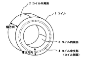
2つ目の方法は、前述のシャワー冷却の条件を調整して、コイルとするときは熱間圧延材全体をMs点以上の温度となるようにする方法である。この2つ目の方法において、シャワー冷却の条件を調整して熱間圧延材全体をMs点以上の温度であるかどうかの判断は、図1に示すコイル1の外周面2、コイル内周面3、およびコイル側面の中央部4のコイル各部位の温度を測定するのが良い。実際には、コイル巻かれた状態の熱間圧延材の温度を正確に測定するのは困難であることから、冷却が速いコイル1の外周面2、コイル内周面3と、冷却が遅いコイル側面の中央部4の3つの部位を測定する。また、冷却の速いコイル1の外周面2、コイル内周面3は、複熱があった場合に、温度が高くなる部位であるため、複熱した場合の温度測定を行う部位としても最適である。
復熱を防止するための方法としては、主に2つの方法がある。
1つ目の方法は、コイルまたはコイルに巻取る前の熱間圧延材を、Ms点未満まで強制的に急冷する方法である。この方法であれば、コイル全体をMs点未満の温度へ確実に冷却することが可能である。ただし、設備の冷却能力が十分でない場合には、1つ目の方法を採用することはできない。
2つ目の方法は、前述のシャワー冷却の条件を調整して、コイルとするときは熱間圧延材全体をMs点以上の温度となるようにする方法である。この2つ目の方法において、シャワー冷却の条件を調整して熱間圧延材全体をMs点以上の温度であるかどうかの判断は、図1に示すコイル1の外周面2、コイル内周面3、およびコイル側面の中央部4のコイル各部位の温度を測定するのが良い。実際には、コイル巻かれた状態の熱間圧延材の温度を正確に測定するのは困難であることから、冷却が速いコイル1の外周面2、コイル内周面3と、冷却が遅いコイル側面の中央部4の3つの部位を測定する。また、冷却の速いコイル1の外周面2、コイル内周面3は、複熱があった場合に、温度が高くなる部位であるため、複熱した場合の温度測定を行う部位としても最適である。
本発明において、前述の2つ目の方法を適用した場合、例えば、巻取りを終了したコイルの3つの各部位が2分経過後にMs点よりも50℃以上高い温度であり、且つ、前述のコイルの各部位の温度が何れも700℃以下であり、且つ、温度差は300℃以内とするのが好ましい。
コイルの3つの部位の何れかが700℃を超えていたり、コイルの3つの部位の最も高温の部位と最も低温の部位の温度差が300℃を超えていると、冷却工程でのコイルの表面と内部との温度差が大きくなり、コイルの内部と表面とで硬度のむらが生じるおそれがある。この2つ目の巻取り冷却方法によれば、外気に曝されて温度低下が著しいコイル外周面及びコイル内周面の温度が、最も温度が高くなるコイル中央部からの熱伝導によって一旦復熱し、コイル内での温度差を軽減した後にコイル全体をMs点未満にほぼ均等な冷却速度で冷却することが可能となるため、設備の冷却能力が1つ目の方法を採用できるほど十分でない場合であっても局部的な復熱によるエージング効果を防止することができる。そのため、特に強力な冷却設備を導入する必要がなく、経済的に有利である。なお、「巻取りを終了」とは、熱間圧延した熱間圧延材の後端がコイルに巻取られた瞬間を言う。
また巻き取り終了後のコイルは、放冷(空冷)や衝風冷却などにより冷却することができる。
何れの方法であっても、局部的な復熱によるエージング効果を防止することができるため、所有する設備に応じて、適宜選択するとよい。
コイルの3つの部位の何れかが700℃を超えていたり、コイルの3つの部位の最も高温の部位と最も低温の部位の温度差が300℃を超えていると、冷却工程でのコイルの表面と内部との温度差が大きくなり、コイルの内部と表面とで硬度のむらが生じるおそれがある。この2つ目の巻取り冷却方法によれば、外気に曝されて温度低下が著しいコイル外周面及びコイル内周面の温度が、最も温度が高くなるコイル中央部からの熱伝導によって一旦復熱し、コイル内での温度差を軽減した後にコイル全体をMs点未満にほぼ均等な冷却速度で冷却することが可能となるため、設備の冷却能力が1つ目の方法を採用できるほど十分でない場合であっても局部的な復熱によるエージング効果を防止することができる。そのため、特に強力な冷却設備を導入する必要がなく、経済的に有利である。なお、「巻取りを終了」とは、熱間圧延した熱間圧延材の後端がコイルに巻取られた瞬間を言う。
また巻き取り終了後のコイルは、放冷(空冷)や衝風冷却などにより冷却することができる。
何れの方法であっても、局部的な復熱によるエージング効果を防止することができるため、所有する設備に応じて、適宜選択するとよい。
以下の実施例で本発明を更に詳しく説明する。
真空溶解で消耗電極を製造し、前記消耗電極を用いて真空アーク再溶解を行って、マルエージング鋼塊を得た。得られたマルエージング鋼塊を熱間鍛造を行って厚さ60mmの熱間圧延素材とした。表2にマルエージング鋼塊の組成を示す。なお、Ms点は220℃である。
真空溶解で消耗電極を製造し、前記消耗電極を用いて真空アーク再溶解を行って、マルエージング鋼塊を得た。得られたマルエージング鋼塊を熱間鍛造を行って厚さ60mmの熱間圧延素材とした。表2にマルエージング鋼塊の組成を示す。なお、Ms点は220℃である。

熱間圧延は、上述の厚さ60mmの熱間圧延用素材を用いて行った。なお、ランアウトテーブル上での強制的な水冷は行わなかった。また、コイルに巻取る直前の熱間圧延材に対してシャワー冷却を開始し、巻取られている最中のコイル状の熱間圧延材もシャワー冷却を行い、巻取りを終了し、巻取りしたコイルは放冷した。
熱間圧延材とコイルの温度測定については赤外線サーモグラフィで測定した。巻取を終了した直後のコイルの温度は260~410℃であり、熱間圧延材の全長にわたりMs点以上の温度であった。また、コイルがMs点以下の温度に冷却した後は、再びMs点以上の温度に復熱しなかった。
熱間圧延終了温度、熱間圧延後の熱間圧延材の厚さ、巻取り終了直後(2分経過後)のコイルの温度と時間経過による温度変化を表3、表4に示す。なお、表3に示す3つの部位の温度測定のうち、「内周面」及び「外周面」は、図1で示すコイル内周面4及びコイル外周面2であり、且つ、熱間圧延材の幅方向の中央付近の測定温度である。また、「中央部」は、図1で示すコイル側面のコイル中央部4を測定した結果である。なお、測定結果に幅があるのは、サーモグラフィで測定した範囲に温度差が生じていたものである。
硬さの測定は、冷却終了後にコイルを解き、前記の「内周面」、「外周面」及び「中央部」に相当する箇所のマルエージング鋼帯から硬さ測定用試験片を採取した。採取した硬さ測定用試験片の酸化スケールを除去し、更に研磨を行って、表面側から硬さを測定したものである。
熱間圧延材とコイルの温度測定については赤外線サーモグラフィで測定した。巻取を終了した直後のコイルの温度は260~410℃であり、熱間圧延材の全長にわたりMs点以上の温度であった。また、コイルがMs点以下の温度に冷却した後は、再びMs点以上の温度に復熱しなかった。
熱間圧延終了温度、熱間圧延後の熱間圧延材の厚さ、巻取り終了直後(2分経過後)のコイルの温度と時間経過による温度変化を表3、表4に示す。なお、表3に示す3つの部位の温度測定のうち、「内周面」及び「外周面」は、図1で示すコイル内周面4及びコイル外周面2であり、且つ、熱間圧延材の幅方向の中央付近の測定温度である。また、「中央部」は、図1で示すコイル側面のコイル中央部4を測定した結果である。なお、測定結果に幅があるのは、サーモグラフィで測定した範囲に温度差が生じていたものである。
硬さの測定は、冷却終了後にコイルを解き、前記の「内周面」、「外周面」及び「中央部」に相当する箇所のマルエージング鋼帯から硬さ測定用試験片を採取した。採取した硬さ測定用試験片の酸化スケールを除去し、更に研磨を行って、表面側から硬さを測定したものである。
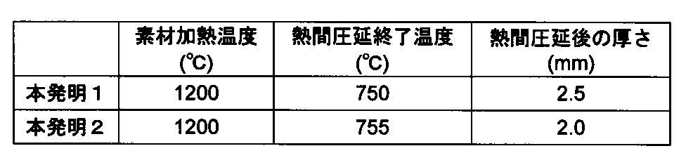

上記に示す通り、本発明の製造方法によれば、コイル内の温度差を小さくすることができた。
また、本発明で規定した巻取り方法で得られたマルエージング鋼コイルは、局所的なエージング効果による硬さの上昇による、硬さむらも見られず、変形等の形状不良も見られなかった。
また、本発明で規定した巻取り方法で得られたマルエージング鋼コイルは、全長にわたり350HV以下の硬さとすることが可能であった。特に、硬さのばらつきはコイル全長にわたり、20HV以内であり、硬さも均一とすることができた。
また、本発明で規定した巻取り方法で得られたマルエージング鋼コイルは、局所的なエージング効果による硬さの上昇による、硬さむらも見られず、変形等の形状不良も見られなかった。
また、本発明で規定した巻取り方法で得られたマルエージング鋼コイルは、全長にわたり350HV以下の硬さとすることが可能であった。特に、硬さのばらつきはコイル全長にわたり、20HV以内であり、硬さも均一とすることができた。
本発明の製造方法はマルエージング鋼に適用可能な他、金属組織の変態点を有する材料に対し、熱間圧延・巻取り時の硬さ変化の問題を持つ素材への適用も可能である。
1 コイル
2 コイル外周面
3 コイル内周面
4 コイル中央部(コイル側面)
2 コイル外周面
3 コイル内周面
4 コイル中央部(コイル側面)
Claims (2)
- マルエージング鋼の熱間圧延用素材を準備する工程と、
前記熱間圧延用素材を加熱する素材加熱工程と、
前記素材加熱工程により加熱された熱間圧延用素材を熱間圧延する熱間圧延工程と、
前記熱間圧延工程により得られた熱間圧延材をコイルに巻取って、前記コイルを冷却する巻取り冷却工程と、
を含むマルエージング鋼コイルの製造方法において、
前記巻取り冷却工程は、巻取り後の前記熱間圧延材がMs点未満に冷却された後は、Ms点以上の温度に再上昇しないように、熱間圧延材を冷却しつつコイルに巻取りを行うことを特徴とするマルエージング鋼コイルの製造方法。 - 巻取りを終了したコイル外周面、コイル内周面およびコイル側面の中央部の温度が、巻取り終了から2分経過後にMs点よりも50℃以上高い温度であり、コイル外周面、コイル内周面およびコイル側面の中央部の温度が何れも700℃以下であり、且つ、コイル外周面、コイル内周面およびコイル側面の中央部の温度差は300℃以内とすることを特徴とする請求項1に記載のマルエージング鋼コイルの製造方法。
Priority Applications (3)
| Application Number | Priority Date | Filing Date | Title |
|---|---|---|---|
| EP13839295.6A EP2899285B1 (en) | 2012-09-21 | 2013-09-19 | Method for manufacturing maraging steel coil |
| JP2014513389A JP5776846B2 (ja) | 2012-09-21 | 2013-09-19 | マルエージング鋼コイルの製造方法 |
| CN201380049147.3A CN104662181B (zh) | 2012-09-21 | 2013-09-19 | 马氏体时效钢卷材的制造方法 |
Applications Claiming Priority (2)
| Application Number | Priority Date | Filing Date | Title |
|---|---|---|---|
| JP2012207707 | 2012-09-21 | ||
| JP2012-207707 | 2012-09-21 |
Publications (1)
| Publication Number | Publication Date |
|---|---|
| WO2014046181A1 true WO2014046181A1 (ja) | 2014-03-27 |
Family
ID=50341485
Family Applications (1)
| Application Number | Title | Priority Date | Filing Date |
|---|---|---|---|
| PCT/JP2013/075302 Ceased WO2014046181A1 (ja) | 2012-09-21 | 2013-09-19 | マルエージング鋼コイルの製造方法 |
Country Status (4)
| Country | Link |
|---|---|
| EP (1) | EP2899285B1 (ja) |
| JP (1) | JP5776846B2 (ja) |
| CN (1) | CN104662181B (ja) |
| WO (1) | WO2014046181A1 (ja) |
Cited By (2)
| Publication number | Priority date | Publication date | Assignee | Title |
|---|---|---|---|---|
| KR101839238B1 (ko) * | 2016-11-10 | 2018-03-15 | 주식회사 포스코 | 연성이 우수한 고탄소 선재 및 이의 제조방법 |
| CN115386695A (zh) * | 2022-08-30 | 2022-11-25 | 河钢股份有限公司 | 30Ni15Cr2Ti2Al合金的轧制及热处理方法 |
Citations (3)
| Publication number | Priority date | Publication date | Assignee | Title |
|---|---|---|---|---|
| JPS60234920A (ja) | 1984-05-04 | 1985-11-21 | Nippon Kokan Kk <Nkk> | 超高張力マルエ−ジング冷延鋼板の製造方法 |
| JP2012140687A (ja) * | 2011-01-05 | 2012-07-26 | Nisshin Steel Co Ltd | Ti含有フェライト系ステンレス鋼熱延コイルおよび製造法 |
| WO2012128272A1 (ja) * | 2011-03-22 | 2012-09-27 | 日立金属株式会社 | 熱間圧延マルエージング鋼帯の巻取り方法 |
Family Cites Families (7)
| Publication number | Priority date | Publication date | Assignee | Title |
|---|---|---|---|---|
| US3878492A (en) * | 1972-10-05 | 1975-04-15 | Asea Ab | Liquid-cooled transformer winding |
| IT1293798B1 (it) * | 1997-07-28 | 1999-03-10 | Techint Spa | Bobinatrice verticale perfezionata per avvolgere in bobina prodotti laminati a caldo. |
| US8337643B2 (en) * | 2004-11-24 | 2012-12-25 | Nucor Corporation | Hot rolled dual phase steel sheet |
| CN101008066B (zh) * | 2006-01-27 | 2010-05-12 | 宝山钢铁股份有限公司 | 抗拉强度高于1000MPa的热轧马氏体钢板及其制造方法 |
| KR101091294B1 (ko) * | 2008-12-24 | 2011-12-07 | 주식회사 포스코 | 고강도 고연신 강판 및 열연강판, 냉연강판, 아연도금강판 및 아연도금합금화강판의 제조방법 |
| JP5533024B2 (ja) * | 2010-02-26 | 2014-06-25 | Jfeスチール株式会社 | 低温靭性に優れた厚肉高張力熱延鋼板の製造方法 |
| CN102605251A (zh) * | 2012-03-28 | 2012-07-25 | 东北大学 | 一种前置式超快冷制备热轧双相钢的方法 |
-
2013
- 2013-09-19 CN CN201380049147.3A patent/CN104662181B/zh active Active
- 2013-09-19 WO PCT/JP2013/075302 patent/WO2014046181A1/ja not_active Ceased
- 2013-09-19 EP EP13839295.6A patent/EP2899285B1/en active Active
- 2013-09-19 JP JP2014513389A patent/JP5776846B2/ja active Active
Patent Citations (3)
| Publication number | Priority date | Publication date | Assignee | Title |
|---|---|---|---|---|
| JPS60234920A (ja) | 1984-05-04 | 1985-11-21 | Nippon Kokan Kk <Nkk> | 超高張力マルエ−ジング冷延鋼板の製造方法 |
| JP2012140687A (ja) * | 2011-01-05 | 2012-07-26 | Nisshin Steel Co Ltd | Ti含有フェライト系ステンレス鋼熱延コイルおよび製造法 |
| WO2012128272A1 (ja) * | 2011-03-22 | 2012-09-27 | 日立金属株式会社 | 熱間圧延マルエージング鋼帯の巻取り方法 |
Non-Patent Citations (1)
| Title |
|---|
| See also references of EP2899285A4 |
Cited By (2)
| Publication number | Priority date | Publication date | Assignee | Title |
|---|---|---|---|---|
| KR101839238B1 (ko) * | 2016-11-10 | 2018-03-15 | 주식회사 포스코 | 연성이 우수한 고탄소 선재 및 이의 제조방법 |
| CN115386695A (zh) * | 2022-08-30 | 2022-11-25 | 河钢股份有限公司 | 30Ni15Cr2Ti2Al合金的轧制及热处理方法 |
Also Published As
| Publication number | Publication date |
|---|---|
| JP5776846B2 (ja) | 2015-09-09 |
| EP2899285A4 (en) | 2016-06-01 |
| JPWO2014046181A1 (ja) | 2016-08-18 |
| CN104662181A (zh) | 2015-05-27 |
| EP2899285B1 (en) | 2018-11-14 |
| CN104662181B (zh) | 2016-10-19 |
| EP2899285A1 (en) | 2015-07-29 |
Similar Documents
| Publication | Publication Date | Title |
|---|---|---|
| CN110088326B (zh) | 热轧扁钢产品及其生产方法 | |
| JP5667977B2 (ja) | 高炭素熱延鋼板およびその製造方法 | |
| JP6082451B2 (ja) | 熱間プレス用鋼板およびその製造方法 | |
| JP2017514989A5 (ja) | ||
| WO2016190370A1 (ja) | 鋼板及びその製造方法 | |
| US10301700B2 (en) | Method for producing a steel component | |
| RU2014104074A (ru) | Способ производства плоского проката из электростали с ориентированной зернистой структурой для применения в электротехнической промышленности | |
| CN103562425A (zh) | 高碳薄钢板及其制造方法 | |
| JP2020510135A (ja) | リッジング性および表面品質に優れたフェライト系ステンレス鋼およびその製造方法 | |
| JP6878060B2 (ja) | フェライト系ステンレス鋼熱延鋼帯 | |
| EP2801635B1 (en) | High carbon hot-rolled steel sheet with excellent hardenability and minimal in-plane anisotropy, and method for producing same | |
| EP2883974B1 (en) | Wire rod having good strength and ductility and method for producing same | |
| JP6070616B2 (ja) | 熱延鋼板の製造方法 | |
| WO2016148045A1 (ja) | 熱間プレス用鋼板およびその製造方法 | |
| JP5776846B2 (ja) | マルエージング鋼コイルの製造方法 | |
| JP4235132B2 (ja) | 磁気特性に優れた無方向性電磁鋼板の製造方法 | |
| JP4715496B2 (ja) | 耐ひずみ時効性に優れ、面内異方性の小さい冷延鋼板の製造方法 | |
| JP2019504213A (ja) | 圧延可能なオーステナイトを含む温間圧延鋼 | |
| JP6948565B2 (ja) | マルテンサイト系ステンレス鋼帯の製造方法 | |
| JP5167314B2 (ja) | 耐リジング性に優れたフェライト系ステンレス鋼の製造方法 | |
| JP5344329B2 (ja) | 熱間圧延マルエージング鋼帯の巻取り方法 | |
| WO2014058938A1 (en) | Cold rolled recovery annealed mild steel and process for manufacture thereof | |
| JP4760455B2 (ja) | 平均r値が高く、面内異方性の小さい冷延鋼板およびその製造方法 | |
| JP6878061B2 (ja) | Ti含有フェライト系ステンレス鋼熱延鋼帯 | |
| JPH0463232A (ja) | 連続焼鈍によるプレス成型性の優れた冷延鋼板の製造法 |
Legal Events
| Date | Code | Title | Description |
|---|---|---|---|
| ENP | Entry into the national phase |
Ref document number: 2014513389 Country of ref document: JP Kind code of ref document: A |
|
| 121 | Ep: the epo has been informed by wipo that ep was designated in this application |
Ref document number: 13839295 Country of ref document: EP Kind code of ref document: A1 |
|
| WWE | Wipo information: entry into national phase |
Ref document number: 2013839295 Country of ref document: EP |
|
| NENP | Non-entry into the national phase |
Ref country code: DE |