WO2014049848A1 - 角形二次電池 - Google Patents
角形二次電池 Download PDFInfo
- Publication number
- WO2014049848A1 WO2014049848A1 PCT/JP2012/075161 JP2012075161W WO2014049848A1 WO 2014049848 A1 WO2014049848 A1 WO 2014049848A1 JP 2012075161 W JP2012075161 W JP 2012075161W WO 2014049848 A1 WO2014049848 A1 WO 2014049848A1
- Authority
- WO
- WIPO (PCT)
- Prior art keywords
- positive electrode
- battery
- secondary battery
- connection electrode
- diaphragm
- Prior art date
- Legal status (The legal status is an assumption and is not a legal conclusion. Google has not performed a legal analysis and makes no representation as to the accuracy of the status listed.)
- Ceased
Links
Images






Classifications
-
- H—ELECTRICITY
- H01—ELECTRIC ELEMENTS
- H01M—PROCESSES OR MEANS, e.g. BATTERIES, FOR THE DIRECT CONVERSION OF CHEMICAL ENERGY INTO ELECTRICAL ENERGY
- H01M50/00—Constructional details or processes of manufacture of the non-active parts of electrochemical cells other than fuel cells, e.g. hybrid cells
- H01M50/50—Current conducting connections for cells or batteries
- H01M50/572—Means for preventing undesired use or discharge
- H01M50/574—Devices or arrangements for the interruption of current
- H01M50/578—Devices or arrangements for the interruption of current in response to pressure
-
- H—ELECTRICITY
- H01—ELECTRIC ELEMENTS
- H01M—PROCESSES OR MEANS, e.g. BATTERIES, FOR THE DIRECT CONVERSION OF CHEMICAL ENERGY INTO ELECTRICAL ENERGY
- H01M50/00—Constructional details or processes of manufacture of the non-active parts of electrochemical cells other than fuel cells, e.g. hybrid cells
- H01M50/10—Primary casings; Jackets or wrappings
- H01M50/102—Primary casings; Jackets or wrappings characterised by their shape or physical structure
- H01M50/103—Primary casings; Jackets or wrappings characterised by their shape or physical structure prismatic or rectangular
-
- H—ELECTRICITY
- H01—ELECTRIC ELEMENTS
- H01M—PROCESSES OR MEANS, e.g. BATTERIES, FOR THE DIRECT CONVERSION OF CHEMICAL ENERGY INTO ELECTRICAL ENERGY
- H01M50/00—Constructional details or processes of manufacture of the non-active parts of electrochemical cells other than fuel cells, e.g. hybrid cells
- H01M50/10—Primary casings; Jackets or wrappings
- H01M50/147—Lids or covers
-
- H—ELECTRICITY
- H01—ELECTRIC ELEMENTS
- H01M—PROCESSES OR MEANS, e.g. BATTERIES, FOR THE DIRECT CONVERSION OF CHEMICAL ENERGY INTO ELECTRICAL ENERGY
- H01M50/00—Constructional details or processes of manufacture of the non-active parts of electrochemical cells other than fuel cells, e.g. hybrid cells
- H01M50/10—Primary casings; Jackets or wrappings
- H01M50/172—Arrangements of electric connectors penetrating the casing
- H01M50/174—Arrangements of electric connectors penetrating the casing adapted for the shape of the cells
- H01M50/176—Arrangements of electric connectors penetrating the casing adapted for the shape of the cells for prismatic or rectangular cells
-
- H—ELECTRICITY
- H01—ELECTRIC ELEMENTS
- H01M—PROCESSES OR MEANS, e.g. BATTERIES, FOR THE DIRECT CONVERSION OF CHEMICAL ENERGY INTO ELECTRICAL ENERGY
- H01M50/00—Constructional details or processes of manufacture of the non-active parts of electrochemical cells other than fuel cells, e.g. hybrid cells
- H01M50/50—Current conducting connections for cells or batteries
- H01M50/543—Terminals
- H01M50/552—Terminals characterised by their shape
- H01M50/553—Terminals adapted for prismatic, pouch or rectangular cells
-
- H—ELECTRICITY
- H01—ELECTRIC ELEMENTS
- H01M—PROCESSES OR MEANS, e.g. BATTERIES, FOR THE DIRECT CONVERSION OF CHEMICAL ENERGY INTO ELECTRICAL ENERGY
- H01M2200/00—Safety devices for primary or secondary batteries
- H01M2200/20—Pressure-sensitive devices
-
- H—ELECTRICITY
- H01—ELECTRIC ELEMENTS
- H01M—PROCESSES OR MEANS, e.g. BATTERIES, FOR THE DIRECT CONVERSION OF CHEMICAL ENERGY INTO ELECTRICAL ENERGY
- H01M2220/00—Batteries for particular applications
- H01M2220/20—Batteries in motive systems, e.g. vehicle, ship, plane
-
- H—ELECTRICITY
- H01—ELECTRIC ELEMENTS
- H01M—PROCESSES OR MEANS, e.g. BATTERIES, FOR THE DIRECT CONVERSION OF CHEMICAL ENERGY INTO ELECTRICAL ENERGY
- H01M50/00—Constructional details or processes of manufacture of the non-active parts of electrochemical cells other than fuel cells, e.g. hybrid cells
- H01M50/10—Primary casings; Jackets or wrappings
- H01M50/147—Lids or covers
- H01M50/155—Lids or covers characterised by the material
- H01M50/157—Inorganic material
- H01M50/159—Metals
-
- H—ELECTRICITY
- H01—ELECTRIC ELEMENTS
- H01M—PROCESSES OR MEANS, e.g. BATTERIES, FOR THE DIRECT CONVERSION OF CHEMICAL ENERGY INTO ELECTRICAL ENERGY
- H01M50/00—Constructional details or processes of manufacture of the non-active parts of electrochemical cells other than fuel cells, e.g. hybrid cells
- H01M50/50—Current conducting connections for cells or batteries
- H01M50/543—Terminals
- H01M50/547—Terminals characterised by the disposition of the terminals on the cells
- H01M50/55—Terminals characterised by the disposition of the terminals on the cells on the same side of the cell
-
- H—ELECTRICITY
- H01—ELECTRIC ELEMENTS
- H01M—PROCESSES OR MEANS, e.g. BATTERIES, FOR THE DIRECT CONVERSION OF CHEMICAL ENERGY INTO ELECTRICAL ENERGY
- H01M50/00—Constructional details or processes of manufacture of the non-active parts of electrochemical cells other than fuel cells, e.g. hybrid cells
- H01M50/50—Current conducting connections for cells or batteries
- H01M50/543—Terminals
- H01M50/562—Terminals characterised by the material
-
- Y—GENERAL TAGGING OF NEW TECHNOLOGICAL DEVELOPMENTS; GENERAL TAGGING OF CROSS-SECTIONAL TECHNOLOGIES SPANNING OVER SEVERAL SECTIONS OF THE IPC; TECHNICAL SUBJECTS COVERED BY FORMER USPC CROSS-REFERENCE ART COLLECTIONS [XRACs] AND DIGESTS
- Y02—TECHNOLOGIES OR APPLICATIONS FOR MITIGATION OR ADAPTATION AGAINST CLIMATE CHANGE
- Y02E—REDUCTION OF GREENHOUSE GAS [GHG] EMISSIONS, RELATED TO ENERGY GENERATION, TRANSMISSION OR DISTRIBUTION
- Y02E60/00—Enabling technologies; Technologies with a potential or indirect contribution to GHG emissions mitigation
- Y02E60/10—Energy storage using batteries
Definitions
- the present invention relates to a square secondary battery used for in-vehicle applications and the like.
- a member that is deformed by the internal pressure of the battery is used at a part of the battery case, and the fragile portion is damaged by the deformation of the member, the current path is blocked, and the inside and outside of the sealed battery are communicated. It has been proposed that the
- Patent Document 1 a sealing body lead and a diaphragm are provided between an external terminal and an internal current collection tab, and the peripheral edge of the diaphragm is sealed in a cylindrical sealing body lead extending in a direction perpendicular to the battery lid. As the internal pressure of the battery rises, the diaphragm is deformed to break the fragile point, thereby blocking the current path.
- the present invention addresses the above problems by stabilizing the weldability of the diaphragm and further making the diaphragm easy to deform so that when the internal pressure rises, the current path can be blocked reliably and stably.
- the purpose is to provide a secondary battery.
- the present invention adopts, for example, the configuration described in the claims.
- the present invention includes a plurality of means for solving the above-mentioned problems, and by way of example, a flat electrode group, a battery can containing the electrode group, and an opening of the battery can are closed.
- a dome-shaped diaphragm portion, and The flange portion covers the through hole of the connection electrode, and the flange portion is joined to the flat portion of the connection electrode. It is characterized by
- the sealing performance is not impaired in the current interrupting mechanism portion, or when the internal pressure rises without causing a malfunction, the electrode can be stably stabilized.
- the current path between the group and the external terminal can be interrupted.
- FIG. 5 is an exploded perspective view of the components shown in FIG. 4;
- FIG. 6 is a view showing a state before the operation of the current interrupting mechanism in the first embodiment.
- FIG. 7 is a view showing a state after operation of the current interrupting mechanism in the first embodiment.
- the fragmentary sectional view of the current interruption mechanism in a 2nd embodiment The fragmentary sectional view of the current interruption mechanism in a 3rd embodiment.
- FIG. 1 is an external perspective view of the lithium ion secondary battery in the present embodiment
- FIG. 2 is an exploded perspective view of the lithium ion secondary battery shown in FIG.
- the lithium ion secondary battery 1 has a battery case 2 having a battery can 4 having a rectangular deep drawn shape and a battery lid 3 for sealing the opening 4a of the battery can 4, as shown in FIGS. 1 and 2.
- a power generation element is accommodated in the battery container 2.
- the power generation element includes a wound electrode group 40 wound flatly in a state in which the separators 43 and 44 are interposed between the positive electrode 41 and the negative electrode 42 and stacked.
- the wound electrode group 40 together with the positive electrode current collector 21 and the negative electrode current collector 31 is inserted into the battery can 4 in a state of being covered by an insulating sheet (not shown) from the outside.
- the battery can 4 and the battery cover 3 are both made of an aluminum alloy, and the battery cover 3 is joined to the battery can 4 by laser welding to seal the opening 4 a.
- the battery lid 3 is provided with a positive electrode side terminal configuration portion 60 and a negative electrode side terminal configuration portion 70 to configure a lid assembly.
- a positive electrode terminal 61 and a negative electrode terminal 71 are disposed between the battery cover 3 and the positive electrode terminal 61 and the negative electrode terminal 70 with the first insulators 64 and 74 interposed therebetween. have.
- the battery cover 3 is opened when the pressure in the battery container 2 rises above a predetermined value, and the gas discharge valve 13 for discharging the gas in the battery container 2;
- a liquid injection port 12 for injecting an electrolytic solution into 2 and a liquid injection plug 11 for sealing the liquid injection port 12 after the injection of the electrolytic solution are disposed.
- the liquid injection plug 11 is joined to the battery lid 3 by laser welding in a state in which the liquid injection port 12 is closed, and seals the liquid injection port 12.
- the positive electrode terminal 61 and the negative electrode terminal 71 are disposed outside the battery lid 3 having a rectangular shape and at mutually separated positions on one side and the other side in the direction along the long side.
- the positive electrode terminal 61 and the negative electrode terminal 71 hold the terminal bolts 63 and 73 for fixing the bus bar connection terminal, and are disposed to the inside of the battery lid 3 and are conductively connected.
- the positive electrode terminal 61 is made of aluminum or an aluminum alloy
- the negative electrode terminal 71 is made of a copper alloy.
- the positive electrode terminal 61 has a gasket 66 and a first insulator 64 interposed on the outside of the battery lid 3 and a second insulator 65 on the inside of the battery lid 3 (see FIG. 4). Electrically insulated from 3.
- the positive electrode terminal 61 is crimped together with the second insulator 65 and the connection electrode 67 and fixed to the battery cover 3.
- the positive electrode terminal 61 is electrically connected to the positive electrode current collector 21 via the current blocking mechanism. The details of the configuration of the current interrupting mechanism will be described later.
- the negative electrode terminal 71 is electrically connected to the negative electrode current collector plate 31 via a connection terminal (not shown).
- the positive electrode current collector plate 21 and the negative electrode current collector plate 31 have a pair of flat joint pieces 23 and 33 extending toward the bottom of the battery can 4 and conductively connected to the wound electrode group 40.
- the respective joining pieces 23 and 33 are joined by welding to the positive electrode and the negative electrode provided at both ends of the wound electrode group 40 in the winding axial direction.
- a welding method ultrasonic welding, resistance welding, laser welding or the like can be used.
- the wound electrode group 40 is disposed between the joint piece 23 of the positive electrode current collector plate 21 and the joint piece 33 of the negative electrode current collector plate 31 and is supported at both ends by the lid assembly and the wound electrode group 40.
- the power generation element assembly 5 is configured.
- FIG. 3 shows the details of the wound electrode group 40 shown in FIG. 2, and is an external perspective view of a state in which the winding end side is expanded.
- the wound electrode group 40 is configured by arranging the negative electrode 42 and the positive electrode 41 between the first and second separators 43 and 44 and winding them in a flat shape. As shown in FIG. 3, in the wound electrode group 40, the outermost electrode is the negative electrode 42, and the separator 44 is further wound on the outer side.
- the separators 43 and 44 have a role of insulating the positive electrode 41 and the negative electrode 42.
- the negative electrode coated portion 42 a of the negative electrode 42 is larger in the width direction than the positive electrode coated portion 41 a of the positive electrode 41, whereby the positive electrode coated portion 41 a is configured to be sandwiched between the negative electrode coated portions 42 a There is.
- the positive electrode uncoated portion 41 b and the negative electrode uncoated portion 42 b are bundled at a flat surface portion and connected to the current collector plates 21 and 31 of respective electrodes connected to the positive electrode terminal 61 and the negative electrode terminal 71 by welding or the like.
- the separators 43 and 44 are wider in the width direction than the negative electrode coated portion 42a, but are wound at a position where the metal foil surface is exposed in the positive electrode uncoated portion 41b and the negative electrode uncoated portion 42b. Does not interfere with welding.
- the positive electrode 41 has a positive electrode coated portion 41a in which a positive electrode active material mixture is applied to both sides of a positive electrode foil as a current collector, and the positive electrode active material is provided at one end of the positive electrode foil in the width direction.
- a positive electrode uncoated portion (foil exposed portion) 41b to which the mixture is not applied is provided.
- the negative electrode 42 has a negative electrode coated portion 42a in which a negative electrode active material mixture is applied to both sides of a negative electrode foil as a current collector, and the negative electrode active material is provided at the other end in the width direction of the positive electrode foil.
- a negative electrode uncoated portion (foil exposed portion) 42b to which the mixture is not applied is provided.
- the positive electrode uncoated portion 41 b and the negative electrode uncoated portion 42 b are regions where the metal surface of the electrode foil is exposed, and as shown in FIG. 3, are disposed at one side and the other side in the winding axial direction.
- PVDF polyvinylidene fluoride
- N amorphous carbon powder
- NMP methyl pyrrolidone
- the present invention is not limited to this, and natural graphite which can insert and desorb lithium ion, and various kinds of artificial graphite
- the material may be a carbonaceous material such as wood or coke, and the particle shape thereof is not particularly limited, such as scaly, spherical, fibrous and massive.
- the positive electrode 41 10 parts by weight of scaly graphite as a conductive material and 10 parts by weight of PVDF as a binder are added to 100 parts by weight of lithium manganate (chemical formula LiMn 2 O 4 ) as a positive electrode active material.
- NMP was added as a dispersion solvent and kneaded, to prepare a positive electrode mixture.
- This positive electrode mixture was applied to both sides of a 20 ⁇ m thick aluminum foil (positive electrode foil), leaving a plain current collecting portion (positive electrode uncoated portion). Thereafter, the resultant was dried, pressed, and cut to obtain a positive electrode having a thickness of 90 ⁇ m and a positive electrode active material coated portion containing no aluminum foil.
- lithium manganate as the positive electrode active material
- other lithium manganate having a spinel crystal structure a lithium manganese composite oxide in which a part is substituted or doped with a metal element
- Lithium cobaltate or lithium titanate having a layered crystal structure Lithium cobaltate or lithium titanate having a layered crystal structure
- a lithium-metal composite oxide in which part of these is substituted or doped with a metal element may be used.
- PVDF polytetrafluoroethylene
- PTFE polytetrafluoroethylene
- polyethylene polystyrene, polybutadiene, butyl rubber, nitrile rubber, Styrene butadiene rubber, polysulfide rubber, nitrocellulose, cyanoethyl cellulose, various latex, polymers such as acrylonitrile, vinyl fluoride, vinylidene fluoride, propylene fluoride, chloroprene fluoride, acrylic resin, and mixtures thereof are used be able to.
- a non-aqueous electrolytic solution is injected from the liquid injection port 12 installed in the battery lid 3.
- a non-aqueous electrolytic solution lithium hexafluorophosphate (LiPF 6 ) dissolved at a concentration of 1 mol / liter in a mixed solution of ethylene carbonate and dimethyl carbonate mixed in a ratio of 1: 2 by volume ratio Can be used.
- the injection port 12 is engaged and closed, and the injection port 12 is sealed by laser welding.
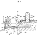
- FIG. 4 shows a cross-sectional view of the current interrupting mechanism
- FIG. 5 shows an exploded perspective view of the component.
- the current blocking mechanism is provided in the current path from the positive electrode terminal 61 of the positive electrode side terminal configuration section 60 to the positive electrode current collector plate 21.
- the positive electrode side terminal component 60 has a positive electrode terminal 61, a positive electrode terminal bolt 63, a first insulator 64, a second insulator 65, a gasket 66, a positive electrode connection electrode 67, a battery It comprises a conductive plate 68 deformed by the rise of the internal pressure, and a positive electrode current collector 21.
- the positive electrode terminal 61, the first insulator 64, the second insulator 65, the gasket 66, and the positive electrode connection electrode 67 are integrally crimped and fixed to the battery inner end surface of the positive electrode terminal 61 and attached to the battery lid 3 There is.
- the positive electrode current collector 21 is integrally fixed to the second insulator 65.
- the positive electrode terminal 61 has a plate-like main body portion 61a disposed along the upper surface which is the outside of the battery lid 3, a bolt insertion hole 61b which penetrates and supports the positive electrode terminal bolt 63 through the main body portion 61a
- the shaft portion 61c is inserted into the opening 3a of the third case 3 and protrudes to the inside of the battery lid 3.
- the shaft portion 61c is provided with a through hole 61d axially penetrating along the center of the shaft portion 61c. .
- the positive electrode terminal bolt 63 is supported by the shaft portion 63a inserted into the bolt insertion hole 61b of the positive electrode terminal 61 and the head portion (bottom flat portion) interposed between the main body portion 61a and the first insulator 64 And 63b.
- the first insulator 64 is formed of an insulating plate-like member interposed between the positive electrode terminal 61 and the upper surface of the battery lid 3, and is in communication with the opening 3 a of the battery lid 3. There is an opening 64a (see FIG. 5) for inserting 61c.
- the gasket 66 is inserted into the opening 3 a of the battery lid 3 to insulate and seal between the shaft portion 61 c of the positive electrode terminal 61 and the battery lid 3.
- the positive electrode connection electrode 67 is formed of a conductive flat plate disposed inside the battery lid 3, and the axial portion 61 c of the positive electrode terminal 61 is inserted into the central position thereof in communication with the opening 3 a of the battery lid 3. An opening 67a is provided.
- the positive electrode connection electrode 67 is disposed along the lower surface of the battery lid 3 with the second insulator 65 interposed between the positive electrode connection electrode 67 and the battery lid 3, and an opening is formed in the planar lower surface (planar portion) 67 b 67a is opened, and the tip of the shaft portion 61c of the positive electrode terminal 61 protruding from the opening 67a is expanded radially outward and crimped, thereby being electrically connected to the positive electrode terminal 61 and insulated from the battery lid 3 In the state, it is integrally fixed to the battery cover 3.
- a crimped portion 61e of the shaft portion 61c of the positive electrode terminal 61 protrudes, and a through hole 61d communicating with the outside of the battery opens toward the inside of the battery.
- the second insulator 65 is formed of an insulating plate-like member disposed along the lower surface of the battery lid 3, and between the battery lid 3 and the positive electrode connection electrode 67, and the battery lid 3 and the positive electrode current collector plate It intervenes between 21 and insulates between them.
- the second insulator 65 has a predetermined thickness, and is provided with a through hole 65 a communicating with the opening 3 a of the battery lid 3 and through which the shaft 61 c of the positive electrode terminal 61 is inserted.
- the second insulator 65 is crimped and fixed integrally to the battery lid 3 together with the positive electrode connection electrode 67 by a crimped portion 61e.
- the second insulator 65 is provided with a recess 65 b in communication with the through hole 65 a and in which the positive electrode connection electrode 67 and the conductive plate 68 are accommodated.
- the recess 65 b is recessed on the lower surface of the second insulator 65 and is in communication with the other space inside the battery.
- the conductive plate 68 has a dome-shaped diaphragm portion 68a whose diameter gradually decreases as it moves in the axial direction, and a ring-shaped flange portion 68b which expands outward in the radial direction from the outer peripheral edge portion of the diaphragm portion 68a There is. Then, the diaphragm portion 68a is opposed to and covers the opening end of the through hole 65a opened in the lower surface 67b of the positive electrode connection electrode 67, and the flange portion 68b is joined to the lower surface 67b of the positive electrode connection electrode 67 and hermetically sealed. A space between the battery outer side and the battery inner side communicated with each other is divided by the through hole 61d.
- the diaphragm portion 68a When the internal pressure of the battery case 2 rises above the preset upper limit value, the diaphragm portion 68a is deformed in the direction in which the protruding height becomes lower due to the pressure difference with the outside of the battery case 2, and the positive electrode collection The fragile portion 25 of the electrode plate 21 is broken, and the junction 24 with the conductive plate 68 is separated from the base 22 of the positive electrode current collector 21 to cut off the current path (see, for example, FIG. 7).
- the diaphragm portion 68a gradually reduces in diameter as it moves in the direction away from the lower surface 67b of the positive electrode connection electrode 67 in the axial direction, and at least a part in the axial direction has a curved surface portion having a convex arc shape. In the present embodiment, it has a hemispherical shape whose cross section is a semi-elliptical shape.
- a flange portion 68 b for joining to the lower surface 67 b of the positive electrode connection electrode 67 is provided at the outer peripheral edge portion of the diaphragm portion 68 a.
- the flange portion 68b extends radially outward along one plane, continues in a constant width over the entire circumference, and has a ring shape facing the lower surface of the positive electrode connection electrode 67. As a result, the entire periphery of the lower surface 67 b of the positive electrode connection electrode 67 is continuously joined and hermetically sealed.
- a central portion 68c which is a top portion of the diaphragm portion 68a is joined to a joint portion 24 of the positive electrode current collector plate 21 by laser welding. Joining of the central portion 68c may be performed by resistance welding or ultrasonic welding other than laser welding.
- the positive electrode current collector plate 21 is attached and fixed to the second insulator 65.
- the positive electrode current collecting plate 21 has a flat plate-like base (upper surface flat portion) 22 extending in parallel to the lower surface of the battery lid 3 and has a plurality of support holes 22b.
- the through holes are formed to be spaced apart from each other by a predetermined distance.
- the base 22 is provided with a pair of edges 22a formed by bending in a direction away from the battery lid 3 along the pair of long sides, and rigidity is improved so as to maintain a planar shape.
- the pair of joining pieces 23 of the positive electrode current collector plate 21 is provided so as to protrude continuously to each edge 22 a.
- the positive electrode current collecting plate 21 inserts a plurality of projections 65c provided on the lower surface of the second insulator 65 into the support holes 22b of the base 22 and thermally welds the tips of the projections 65c. It is joined to the second insulator 65 and fixed integrally.
- the positive electrode current collector plate 21 is provided with a bonding portion 24 bonded to the central portion 68 c of the conductive plate 68.
- the joint portion 24 is configured by a thin portion obtained by thinning a part of the base 22.
- the fragile portion 25 is configured by providing a groove portion in the thin-walled portion so as to surround the periphery of the bonding portion 24, and is disconnected at the groove portion by the conductive plate 68 that deforms in the outward direction of the battery when the battery internal pressure rises.
- the joint 24 can be separated from the base 22.
- the fragile portion 25 is broken when a force in the pulling direction acts on the battery lid 3 side due to the deformation of the conductive plate 68 due to the increase of the internal pressure of the battery container 2, and under normal use environment such as vibration during traveling In the above, the dimensions and shape etc. are set so that the strength does not break. Bonding between the central portion 68c of the conductive plate 68 and the bonding portion 24 of the positive electrode current collector plate 21 is performed by laser welding, but resistance welding, ultrasonic welding or the like is also possible.
- the conductive plate 68 moves in the direction in which the protruding height decreases due to the pressure difference with the outside of the battery case 2. Is deformed. Then, the joint portion 24 surrounded by the fragile portion 25 of the positive electrode current collector plate 21 is pulled in the direction orthogonal to the base 22, and the fragile portion 25 of the positive electrode current collector plate 21 is fractured. The current path between the positive electrode terminal 61 and the positive electrode current collector 21 is cut off from the base 22 of the positive electrode current collector 21.
- the first insulator 64 and the gasket 66 are arranged in alignment with the opening 3 a of the battery cover 3 on the battery outside of the battery cover 3. Then, the head portion 63 b of the positive electrode terminal bolt 63 is inserted into the recess 64 b provided in the first insulator 64, and the shaft portion 61 c of the positive electrode terminal 61 is inserted into the opening 64 a above the first insulator 64. The shaft portion 63 a of the positive electrode terminal bolt 63 is inserted into the bolt insertion hole 61 b of the positive electrode terminal 61.
- the second insulator 65 is superimposed on the battery inside of the battery lid 3 so that the second insulator 65 is interposed between the battery lid 3 and the positive electrode connection electrode 67, and the through holes 65 a of the second insulator 65
- the second insulator 65 and the positive electrode connection electrode 67 are arranged such that the openings 67a of the positive electrode connection electrode 67 are arranged concentrically.
- the positive electrode terminal 61 is made to approach from the battery outside of the battery cover 3, and the main body 61 a of the positive electrode terminal 61 is superimposed on the first insulator 64.
- the tip of the shaft 61c is caulked.
- the outer diameter of the caulking punch is slightly larger than the outer diameter of the caulking portion 61e. If projections such as ribs and projections are present on the lower surface 67b of the positive electrode connection electrode 67, interference will not occur and caulking can not be performed, so it is necessary to reduce the outer diameter of the caulking punch accordingly. If the outer diameter of the caulking portion 61e is reduced, the caulked area may be reduced and caulking strength may be reduced.
- the positive electrode connection electrode 67 in the lithium ion secondary battery 1 of the present embodiment is a flat plate member, the lower surface 67 b is flat, and there is no protrusion such as a rib or a protrusion. Therefore, it is possible to secure a larger crimped outer diameter by that much, and it is possible to obtain a higher crimped strength, which is advantageous.
- the positive electrode connection electrode 67 is fixed to the battery lid 3 by caulking the tip of the shaft portion 61c of the positive electrode terminal 61, the size of the positive electrode connection electrode 67 affects the positive electrode connection electrode 67. Without, the outside diameter of the caulking punch can be set.
- the conductive plate 68 has a dome shape so as to avoid the caulking portion 61e of the positive electrode terminal 61, so that a larger surface area of the conductive plate 68 can be secured with less space. Therefore, when the internal pressure of the battery container 2 is increased, the conductive plate 68 is easily deformed, and a reliable current interruption can be performed at a lower pressure.
- the positive current collector plate 21 is provided with several support holes 22b in the base 22, and the second insulator 65 is used.
- the convex part 65c penetrated by the support hole 22b is provided in the position which opposes the support hole 22b in the battery inner side flat part which is the lower surface of the.
- the positive electrode current collector plate 21 is joined to the second insulator 65 by inserting the convex portion 65 c into the support hole 22 b and thermally welding the tip of the convex portion 65 c.
- the positive electrode current collector plate 21 is joined by thermal welding to the battery lid 3 and the second insulator 65 fixed firmly by caulking, so that external vibration and impact applied to the positive electrode current collector plate 21 are not generated. On the other hand, it is possible to suppress an adverse effect on the fragile portion 25 and the joint portion 24 of the base 22.
- fixation of the positive electrode current collection board 21 and the 2nd insulator 65 although the case of heat welding was described as an example, since a process process is easy, when stronger joining is required, heat is used. Instead of welding, or in combination with heat welding, it is also possible to use at least one of a screw, a rivet and an adhesive.
- the bonding portion 24 of the positive electrode current collector plate 21 is bonded to the central portion 68 c of the conductive plate 68.
- the joint portion 24 of the positive electrode current collector plate 21 is joined to the central portion 68 c of the conductive plate 68 by welding. Bonding between the central portion 68c of the conductive plate 68 and the bonding portion 24 of the positive electrode current collector plate 21 can be resistance welding, ultrasonic welding, etc. in addition to laser welding.
- the positive electrode side terminal configuration portion 60 is manufactured through the steps of (1), (2) and (3) described above.
- the positive electrode current collector 21, the conductive plate 68, the positive electrode connection electrode 67, the positive electrode terminal 61, and the positive electrode terminal bolt 63 are electrically connected.
- the battery cover 3 is insulated by the gasket 66 and the second insulator 65.
- the positive electrode current collector 21, the conductive plate 68, and the positive electrode connection electrode 67 are formed of aluminum or an aluminum alloy.
- the positive electrode side is made of an aluminum alloy and the negative electrode side is made of a copper alloy, the aluminum alloy is more easily deformed than the copper alloy, and is easily broken. Therefore, in the present embodiment, the current blocking mechanism is provided on the positive electrode side.
- the positive electrode current collector plate 21 and the negative electrode current collector plate 31 are wound electrode groups 40 are joined, and the power generation element assembly 5 is assembled.
- the positive electrode current collector 21 and the negative electrode current collector 31 are covered with the insulating sheet (not shown) around the wound electrode group 40 and inserted into the battery can 4, and the opening 4 a of the battery can 4 is It is closed by the lid 3 and the battery lid 3 is joined and sealed to the battery can 4 by laser welding.
- an electrolytic solution is injected into the battery container 2 from the injection port 12, the injection port 12 is closed by the injection plug 11, and the battery lid 3 is joined and sealed by laser welding.
- the lithium ion secondary battery 1 assembled by the above-described assembling operation can be charged and discharged to an external electronic device connected by the positive electrode terminal 61 and the positive electrode terminal bolt 63 and the negative electrode terminal 71 and the negative electrode terminal bolt 73 become.
- the lithium ion secondary battery 1 in the present embodiment can exhibit the following effects.
- the current interrupting mechanism is interposed in the current path between the wound electrode group 40 and the positive electrode terminal 61 (external terminal), so that the fragile portion of the current interrupting mechanism is broken in an unexpected situation such as overcharging, for example. Therefore, the safety can be largely maintained, but the fragile portion or the welded joint portion may damage the sealing performance such as breakage due to external vibration or impact, which may cause malfunction or quality deterioration.
- the lithium ion secondary battery 1 of the present embodiment includes the positive electrode connection electrode 67 formed of a flat plate member and the conductive plate 68 having the dome-shaped diaphragm portion 68. It welds in the state which the flange part 68b of the electrically conductive board 68 surface-contacted to the lower surface 67b, and it has the structure sealed airtightly between the positive electrode connection electrode 67 and the electrically conductive board 68.
- the component shapes of the positive electrode connection electrode 67 and the conductive plate 68 which are sealing parts can be simplified as compared with the conventional case, and the planarity of the lower surface 67 b of the positive electrode connection electrode 67 is utilized to The weldability between can be stabilized.
- the diaphragm portion 68a of the conductive plate 68 has a dome shape, it can receive pressure in a wider area by the rise in the battery internal pressure as compared with the flat plate type, and within a limited space A stress sufficient to deform the conductive plate 68 and break the fragile portion 25 can be easily obtained. Therefore, the rigidity of the fragile portion 25 can be relatively strengthened even at the same setting of the breaking pressure, and the fragile portion 25 is prevented from breaking due to vibration or impact, and when the internal pressure rises, the current is reliably and stably You can block the path.
- the lithium ion secondary battery 1 since the lithium ion secondary battery 1 has a structure for fixing the positive electrode current collector plate 21 to the second insulator 65, vibration or shock is applied to the bonding portion 24 and the fragile portion 25. Can be suppressed.
- the positive electrode current collector plate 21 is joined by heat welding or the like to the second insulator 65 firmly fixed to the battery lid 3 by caulking, external vibration or impact applied to the positive electrode current collector plate 21 is joined.
- the lithium ion secondary battery 1 having the current blocking mechanism which has increased rigidity against vibration and impact.
- FIG. 8 is a view showing a partial cross-sectional view of the current interrupting mechanism in the second embodiment.
- the detailed description is abbreviate
- a characteristic feature of this embodiment is that a circumferential rib 67c is provided on the outer peripheral portion of the lower surface 67b of the positive electrode connection electrode 67 to which the conductive plate 68 is joined, in which the flange portion 68b of the conductive plate 68 is inserted and fixed. It is
- the rib 67 c is provided on the outer end surface of the flange portion 68 b so as to face the entire circumference at the radially outer position of the flange portion 68 b of the conductive plate 68. And it has the height which becomes flush with flange part 68b. Then, the boundary between the outer end surface of the flange portion 68 b and the opposing surface of the rib 67 c facing it is joined by laser welding, and the space between the positive electrode connection electrode 67 and the conductive plate 68 is hermetically sealed.
- the conductive plate 68 is inserted and fixed by the rib 67c, and the positioning becomes easy, and the difference in level between the flange portion 68b of the conductive plate 68 and the positive electrode connection electrode 67 disappears
- the welding energy can also be suppressed to a lower level, and the welding quality is more stabilized when laser welding the boundary between the positive electrode connection electrode 67 and the conductive plate 68.
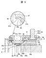
- FIG. 9 is a view showing a partial cross-sectional view of the current interrupting mechanism in the third embodiment.
- the detailed description is abbreviate
- a characteristic feature of this embodiment is that an annular concave groove 67d is provided on the lower surface 67b of the positive electrode connection electrode 67 to which the conductive plate 68 is joined, in which the flange portion 68b of the conductive plate 68 is inserted and fixed. .
- the recessed groove 67d is a groove shape having a depth such that the outer end surface of the flange portion 68b faces the outer peripheral side vertical wall surface of the recessed groove 67d by inserting the flange portion 68b and the flange portion 68b is flush with the lower surface 67b. have. Then, the boundary between the outer peripheral side vertical wall surface of the recessed groove 67d and the outer end face of the flange portion 68b opposed thereto is joined by laser welding, and the space between the positive electrode connection electrode 67 and the conductive plate 68 is hermetically sealed.
- the flange portion 68b when laser welding is performed, the flange portion 68b is fitted and fixed to the recessed groove 67d, the positioning of the conductive plate 68 is facilitated, and the flange portion 68b of the conductive plate 68
- the welding energy can also be suppressed to a lower level, and the welding quality is further stabilized when laser welding the boundary between the positive electrode connection electrode 67 and the conductive plate 68.
- the outer diameter of the caulking punch at the time of caulking can be set larger. Therefore, the caulking strength can be made higher.
- FIG. 10 is a view showing a partial cross-sectional view of the current interrupting mechanism in the fourth embodiment.
- the detailed description is abbreviate
- a characteristic feature of this embodiment is that the diameter of the dome-shaped diaphragm portion 68a of the conductive plate 68 is gradually reduced as it moves away from the positive electrode connection electrode 67 along the axial direction.
- a smooth surface portion having a linear shape and a curved surface portion having a circular arc shape in cross section are arranged in the axial direction to form a three-dimensional shape.
- the diaphragm 68a has a hemispherical shape with a semi-elliptical cross section has been described as an example.
- the diaphragm portion 68a of the conductive plate 68 in the present embodiment gradually reduces its diameter as it moves away from the lower surface 67b of the positive electrode connection electrode 67, and has a smooth surface portion whose cross section is linear, and an arc whose cross section is a convex It has the three-dimensional shape which put in order and combined the curved surface part used as a shape in the axial direction.
- a smooth surface 68 d continuous with the flange 68 b is provided on the side approaching the positive electrode connection electrode 67, and a curved surface 68 e is provided on the side separating from the positive electrode connection electrode 67.
- a refracting portion 68h (a boundary formed by a combination of a partially curved surface and a smooth surface) refracted in a circular arc shape is provided at the boundary between the smooth surface portion and the curved surface portion.
- the smooth surface portion 68d is partially provided in the central direction from the position where the conductive plate 68 is joined to the positive electrode connection electrode 67.
- the diaphragm portion 68a can be efficiently deformed in the battery outer direction, which is the direction in which the height is lowered, and fracture at low pressure can be operated more stably. become. Also, depending on the shape of the convex height of caulking portion 61e, a curved surface portion is partially provided in the central direction from the position where conductive plate 68 is joined to positive electrode connection electrode 67 contrary to this. A smooth surface portion may be provided in the direction.
- a single curved surface portion and a single smooth surface portion are combined is described as to the shape of the diaphragm portion 68a of the conductive plate 68, the present invention is not limited to this.
- a plurality of curved surface portions and smooth surface portions may be provided, or a combination of a plurality of curved surface portions having different curvatures or a combination of a plurality of smooth surface portions having different inclination angles may be used.
- the case of the concave groove (see FIG. 9) 67d shown in the third embodiment is shown as an example.
- FIG. 11 is a view showing a partial cross-sectional view of the current interrupting mechanism in the fifth embodiment.
- the detailed description is abbreviate
- the characteristic feature of this embodiment is that the first inclined surface 68f gradually reduces the diameter of the dome-shaped diaphragm 68a of the conductive plate 68 as it moves away from the positive electrode connection electrode 67 in the axial direction.
- This is a three-dimensional shape having a substantially W-shaped cross section in combination with the second sloped surface portion 68g which gradually reduces in diameter as it moves from the first sloped surface portion 68f toward the positive electrode connection electrode 67. Then, at a boundary between the first inclined surface 68f and the second inclined surface 68g, a refracting portion 68h which is refracted in an arc shape in cross section is provided.
- the first inclined surface portion 68f and the second inclined surface portion 68g both have smooth surface shapes in which the cross section becomes a linear shape, but one or both have a curved surface shape in which the cross section has an arc shape
- the first sloped surface portion 68f has a curved surface shape in which the cross section has a convex arc shape (convex toward the inside of the battery)
- the second sloped surface portion 68g has a concave cross section. It is good also as what has a curved surface shape used as a circular arc shape (it becomes convex toward the battery outside).
- the case of the concave groove (see FIG. 9) shown in the third embodiment is shown as an example.
- the present invention is not limited to the above-mentioned embodiment, and various designs are possible in the range which does not deviate from the spirit of the present invention described in the claim. It is possible to make changes.
- the above-described embodiment has been described in detail in order to explain the present invention in an easy-to-understand manner, and is not necessarily limited to one having all the described configurations.
- part of the configuration of one embodiment can be replaced with the configuration of another embodiment, and the configuration of another embodiment can be added to the configuration of one embodiment.
- Lithium ion secondary battery (square secondary battery) DESCRIPTION OF SYMBOLS 2 battery container 3 battery cover 4 battery can 21 positive electrode current collecting plate 24 joining part 25 weak part 31 negative electrode current collecting plate 40 electrode group 60 positive electrode side terminal structure part 61 positive electrode terminal (external terminal) 61 d through hole 64 first insulator 65 second insulator 66 gasket 67 positive electrode connection electrode 67 b lower surface (planar portion) 67c rib 67d recessed groove 68 conductive plate 68a diaphragm portion 68b flange portion 68c central portion 68d smooth surface portion 68e curved surface portion 68h bent portion 68f first inclined surface portion 68g second inclined surface portion
Landscapes
- Chemical & Material Sciences (AREA)
- Chemical Kinetics & Catalysis (AREA)
- Electrochemistry (AREA)
- General Chemical & Material Sciences (AREA)
- Connection Of Batteries Or Terminals (AREA)
- Sealing Battery Cases Or Jackets (AREA)
Description
図1は、本実施形態におけるリチウムイオン二次電池の外観斜視図、図2は、図1に示されるリチウムイオン二次電池の分解斜視図である。
正極端子61は、電流遮断機構を間に介して正極集電板21に電気的に接続されている。なお、電流遮断機構の構成についての詳細は後述する。負極端子71は、接続端子(図示せず)を間に介して負極集電板31に電気的に接続されている。
まず、電池蓋3の電池外側にて、第1の絶縁体64とガスケット66を電池蓋3の開口部3aに位置合わせして配置する。そして、正極端子ボルト63のヘッド部63bを第1の絶縁体64に設けられた凹部64bに挿入し、正極端子61の軸部61cを第1の絶縁体64上で開口部64aに挿入すると共に、正極端子61のボルト挿通孔61bに正極端子ボルト63の軸部63aを挿入する。
正極接続電極67の下面67bに、導電板68のフランジ部68bを接面させて、レーザー溶接により互いに接合し、密閉封止する。
正極集電板21は、基部22に数箇所の支持穴22bが設けられており、第2の絶縁体65の下面である電池内側平面部でかつ支持穴22bに対向する位置には、支持穴22bに挿通される凸部65cが設けられている。この凸部65cを支持穴22bに挿入して凸部65cの先端を熱溶着することにより、正極集電板21を第2の絶縁体65に接合する。
次に、第2実施形態について、図8を用いて説明する。
次に、第3実施形態について、図9を用いて説明する。
次に、第4実施形態について、図10を用いて説明する。
次に、第5実施形態について、図11を用いて説明する。
2 電池容器
3 電池蓋
4 電池缶
21 正極集電板
24 接合部
25 脆弱部
31 負極集電板
40 電極群
60 正極側端子構成部
61 正極端子(外部端子)
61d 貫通孔
64 第1の絶縁体
65 第2の絶縁体
66 ガスケット
67 正極接続電極
67b 下面(平面部)
67c リブ
67d 凹溝
68 導電板
68a ダイアフラム部
68b フランジ部
68c 中央部
68d 平滑面部
68e 湾曲面部
68h 屈折部
68f 第1傾斜面部
68g 第2傾斜面部
Claims (14)
- 扁平状の電極群と、該電極群を収容する電池缶と、該電池缶の開口部を閉塞する電池蓋と、該電池蓋に設けられる外部端子と、該外部端子と前記電極群との間を電気的に接続する電流経路の途中に介在されて電池内圧の上昇により前記電流経路を遮断する電流遮断機構と、を有する角形二次電池であって、
前記電流遮断機構は、
前記電池蓋の内側に配置されて前記外部端子に電気的に接続される接続電極と、該接続電極に接合されて電池内圧の上昇により変形する導電板を有し、
前記接続電極は、電池外側に連通する貫通孔が平面部に開口する平板部材からなり、
前記導電板は、軸方向に移行するにしたがって漸次縮径するドーム状のダイアフラム部と、該ダイアフラム部の外形周縁部から径方向外側に向かって拡がるリング状のフランジ部とを有し、前記ダイアフラム部が前記接続電極の前記貫通孔を覆い、前記フランジ部が前記接続電極の平面部に接合されていることを特徴とする角形二次電池。 - 前記接続電極の平面部には、前記フランジ部が嵌入される環状の凹溝が設けられており、該凹溝の外側縦壁面と前記フランジ部の外端面との境目が溶接により接合されて密閉封止されていることを特徴とする請求項1に記載の角形二次電池。
- 前記接続電極の平面部には、前記フランジ部の外端面に全周に亘って対向するリブが設けられており、該リブの対向面と前記フランジ部との間が溶接により接合されて密閉封止されていることを特徴とする請求項1に記載の角形二次電池。
- 前記ダイアフラム部は、前記軸方向の少なくとも一部に断面が凸状の円弧形状となる湾曲面部を有することを特徴とする請求項1から請求項3のいずれか一項に記載の角形二次電池。
- 前記ダイアフラム部は、前記軸方向の少なくとも一部に断面が直線形状となる平滑面部を有することを特徴とする請求項1から請求項3のいずれか一項に記載の角形二次電池。
- 前記ダイアフラム部は、断面が凸状の円弧形状となる湾曲面部と、断面が直線形状となる平滑面部とを前記軸方向に並べて組み合わせた立体形状を有することを特徴とする請求項1から請求項3のいずれか一項に記載の角形二次電池。
- 前記湾曲面部と前記平滑面部との間の境界部分には、断面円弧状に屈折した屈折部が設けられていることを特徴とする請求項6に記載の角形二次電池。
- 前記ダイアフラム部は、断面が直線形状となりかつ前記軸方向に対する傾斜角が互いに異なる複数の平滑面部を前記軸方向に並べて組み合わせた立体形状を有することを特徴とする請求項1から請求項3のいずれか一項に記載の角形二次電池。
- 前記複数の平滑面部の間の境界部分には、断面円弧状に屈折した屈折部が設けられていることを特徴とする請求項8に記載の角形二次電池。
- 前記ダイアフラム部は、前記軸方向に沿って前記接続電極から離反する方向に移行するにしたがって漸次縮径する第1傾斜面部と、該第1傾斜面部から前記軸方向に沿って前記接続電極に接近する方向に移行するにしたがって漸次縮径する第2傾斜面部とを有することを特徴とする請求項1から請求項3のいずれか一項に記載の角形二次電池。
- 前記第1傾斜面部と前記第2傾斜面部との間の境界部分には、断面が凸状の円弧形状を有して屈折した屈折部が設けられていることを特徴とする請求項10に記載の角形二次電池。
- 前記電極群に電気的に接続される集電板を有し、
該集電板は、前記導電板の前記ダイアフラム部の中央部と接合される接合部と、該接合部の周囲に形成されて前記ダイアフラム部の変形により破断される脆弱部と、を有することを特徴とする請求項1に記載の角形二次電池。 - 前記電池蓋と前記接続電極との間に介在されて、前記接続電極と共に前記電池蓋に一体にかしめ固定される第2の絶縁体を有し、
前記集電板は、前記第2の絶縁体に熱溶着、ネジ、リベット、接着剤の少なくともいずれか一つによって接合されて固定されていることを特徴とする請求項12に記載の角形二次電池。 - 前記電極群の正極電極に接続される前記集電板、前記導電板、前記接続電極、前記正極外部端子は、アルミニウムまたはアルミニウム合金で製作されていることを特徴とする請求項12に記載の角形二次電池。
Priority Applications (5)
| Application Number | Priority Date | Filing Date | Title |
|---|---|---|---|
| JP2014538045A JP6005172B2 (ja) | 2012-09-28 | 2012-09-28 | 角形二次電池 |
| EP12885554.1A EP2903056B1 (en) | 2012-09-28 | 2012-09-28 | Rectangular secondary battery |
| US14/420,836 US9741994B2 (en) | 2012-09-28 | 2012-09-28 | Secondary battery with current breaking mechanism |
| PCT/JP2012/075161 WO2014049848A1 (ja) | 2012-09-28 | 2012-09-28 | 角形二次電池 |
| CN201280075245.XA CN104641492B (zh) | 2012-09-28 | 2012-09-28 | 方形二次电池 |
Applications Claiming Priority (1)
| Application Number | Priority Date | Filing Date | Title |
|---|---|---|---|
| PCT/JP2012/075161 WO2014049848A1 (ja) | 2012-09-28 | 2012-09-28 | 角形二次電池 |
Publications (1)
| Publication Number | Publication Date |
|---|---|
| WO2014049848A1 true WO2014049848A1 (ja) | 2014-04-03 |
Family
ID=50387309
Family Applications (1)
| Application Number | Title | Priority Date | Filing Date |
|---|---|---|---|
| PCT/JP2012/075161 Ceased WO2014049848A1 (ja) | 2012-09-28 | 2012-09-28 | 角形二次電池 |
Country Status (5)
| Country | Link |
|---|---|
| US (1) | US9741994B2 (ja) |
| EP (1) | EP2903056B1 (ja) |
| JP (1) | JP6005172B2 (ja) |
| CN (1) | CN104641492B (ja) |
| WO (1) | WO2014049848A1 (ja) |
Cited By (11)
| Publication number | Priority date | Publication date | Assignee | Title |
|---|---|---|---|---|
| JP2014229416A (ja) * | 2013-05-21 | 2014-12-08 | 株式会社豊田自動織機 | 蓄電装置 |
| JP2016012459A (ja) * | 2014-06-27 | 2016-01-21 | 日立オートモティブシステムズ株式会社 | 二次電池 |
| JP2016015228A (ja) * | 2014-07-01 | 2016-01-28 | 株式会社豊田自動織機 | 電流遮断装置、蓄電装置、電流遮断装置の製造方法、および蓄電装置の製造方法 |
| JP2016076300A (ja) * | 2014-10-02 | 2016-05-12 | 株式会社豊田自動織機 | 電流遮断装置を備えた蓄電装置 |
| JP2016170873A (ja) * | 2015-03-11 | 2016-09-23 | トヨタ自動車株式会社 | 電流遮断装置 |
| JP2017027896A (ja) * | 2015-07-27 | 2017-02-02 | 株式会社豊田自動織機 | 電流遮断装置、蓄電装置、電流遮断装置の製造方法、および蓄電装置の製造方法 |
| JP2017045657A (ja) * | 2015-08-27 | 2017-03-02 | 株式会社豊田自動織機 | 電流遮断装置及びこれを用いた蓄電装置 |
| WO2019216018A1 (ja) * | 2018-05-07 | 2019-11-14 | 本田技研工業株式会社 | 非水電解質二次電池 |
| JP2021507480A (ja) * | 2017-12-22 | 2021-02-22 | ビーワイディー カンパニー リミテッド | 電池カバープレートアセンブリ、単電池、電池モジュール、動力電池及び電気自動車 |
| JP2023174483A (ja) * | 2022-05-25 | 2023-12-07 | 瑞浦蘭鈞能源股分有限公司 | 二次電池のトップカバー構造、トップカバーアセンブリ及び二次電池 |
| JP2024070205A (ja) * | 2022-11-10 | 2024-05-22 | 寧波震裕汽車部件有限公司 | 電池トップカバーアセンブリ |
Families Citing this family (20)
| Publication number | Priority date | Publication date | Assignee | Title |
|---|---|---|---|---|
| US11552377B2 (en) | 2012-11-26 | 2023-01-10 | Vehicle Energy Japan Inc. | Rectangular secondary battery |
| JP6661485B2 (ja) * | 2015-09-16 | 2020-03-11 | パナソニック株式会社 | 非水電解質二次電池 |
| KR102496396B1 (ko) * | 2015-12-03 | 2023-02-06 | 삼성에스디아이 주식회사 | 이차전지 |
| CN205790098U (zh) * | 2016-02-25 | 2016-12-07 | 比亚迪股份有限公司 | 电流中断装置、单体电池、电池模组、动力电池及电动汽车 |
| CN107123776B (zh) * | 2016-02-25 | 2019-11-08 | 比亚迪股份有限公司 | 单体电池、电池模组、动力电池及电动汽车 |
| CN107123774B (zh) * | 2016-02-25 | 2019-10-11 | 比亚迪股份有限公司 | 单体电池、电池模组、动力电池及电动汽车 |
| EP3422434A4 (en) * | 2016-02-25 | 2019-03-27 | BYD Company Limited | ONE-SINGLE BATTERY, BATTERY MODULE, POWER BATTERY AND ELECTRIC VEHICLE |
| JP6821309B2 (ja) * | 2016-03-07 | 2021-01-27 | 三洋電機株式会社 | 二次電池および二次電池集合体 |
| CN105826504B (zh) * | 2016-05-31 | 2019-05-14 | 力神电池(苏州)有限公司 | 孔板及锂离子电池的电流阻断结构 |
| CN105870366B (zh) * | 2016-06-07 | 2019-03-15 | 宁德时代新能源科技股份有限公司 | 动力电池顶盖及动力电池 |
| CN105845851B (zh) * | 2016-06-07 | 2018-07-17 | 宁德时代新能源科技股份有限公司 | 动力电池顶盖及其动力电池 |
| CN105845850B (zh) * | 2016-06-07 | 2019-01-08 | 宁德时代新能源科技股份有限公司 | 动力电池顶盖及其动力电池 |
| JP6750816B2 (ja) * | 2016-09-09 | 2020-09-02 | 三洋電機株式会社 | 二次電池 |
| CN108232052B (zh) * | 2016-12-09 | 2020-12-11 | 宁德时代新能源科技股份有限公司 | 二次电池 |
| JP6947575B2 (ja) * | 2017-07-31 | 2021-10-13 | 株式会社Gsユアサ | 蓄電素子の製造方法 |
| CN109920963B (zh) * | 2017-12-13 | 2024-10-15 | 比亚迪股份有限公司 | 电池盖板组件、单体电池、电池模组、动力电池及电动汽车 |
| WO2019130502A1 (ja) * | 2017-12-27 | 2019-07-04 | 株式会社 東芝 | 二次電池の製造方法 |
| JP7001957B2 (ja) * | 2018-03-02 | 2022-01-20 | トヨタ自動車株式会社 | 電池の製造方法および電池 |
| CN111063943B (zh) * | 2019-11-11 | 2023-04-18 | 安徽理士电源技术有限公司 | 带有耐振支撑结构的铅酸蓄电池 |
| CN121863017A (zh) * | 2021-02-19 | 2026-04-14 | 株式会社Lg新能源 | 电极端子的铆接结构及包括其的二次电池、电池组及汽车 |
Citations (6)
| Publication number | Priority date | Publication date | Assignee | Title |
|---|---|---|---|---|
| JPH09180698A (ja) * | 1995-12-23 | 1997-07-11 | Sony Corp | 密封型非水電解質角型二次電池 |
| JPH1131491A (ja) * | 1997-07-09 | 1999-02-02 | Matsushita Electric Ind Co Ltd | 密閉型電池用防爆封口板およびその製造方法 |
| JPH11120979A (ja) * | 1997-09-29 | 1999-04-30 | Samsung Display Devices Co Ltd | 方形電池のキャップ組立体 |
| JP2008066255A (ja) | 2006-08-11 | 2008-03-21 | Sanyo Electric Co Ltd | 非水電解質二次電池 |
| JP2010157451A (ja) * | 2008-12-27 | 2010-07-15 | Sanyo Electric Co Ltd | 車両用の電源装置 |
| JP2012119183A (ja) * | 2010-12-01 | 2012-06-21 | Toyota Motor Corp | 密閉型電池 |
Family Cites Families (6)
| Publication number | Priority date | Publication date | Assignee | Title |
|---|---|---|---|---|
| JPH07326337A (ja) * | 1994-05-27 | 1995-12-12 | Nippondenso Co Ltd | 化学電池 |
| US6210824B1 (en) * | 1998-01-15 | 2001-04-03 | Texas Instruments Incorporated | Current interrupt apparatus for electrochemical cells |
| JPH11329405A (ja) * | 1998-05-21 | 1999-11-30 | At Battery:Kk | 非水電解液二次電池 |
| JP4346637B2 (ja) * | 2006-11-24 | 2009-10-21 | 日立ビークルエナジー株式会社 | 円筒型二次電池 |
| KR101023104B1 (ko) * | 2008-12-26 | 2011-03-24 | 에스비리모티브 주식회사 | 이차 전지 |
| JP5430978B2 (ja) | 2009-03-10 | 2014-03-05 | 三洋電機株式会社 | 密閉電池及びその製造方法 |
-
2012
- 2012-09-28 CN CN201280075245.XA patent/CN104641492B/zh active Active
- 2012-09-28 JP JP2014538045A patent/JP6005172B2/ja active Active
- 2012-09-28 WO PCT/JP2012/075161 patent/WO2014049848A1/ja not_active Ceased
- 2012-09-28 EP EP12885554.1A patent/EP2903056B1/en active Active
- 2012-09-28 US US14/420,836 patent/US9741994B2/en active Active
Patent Citations (6)
| Publication number | Priority date | Publication date | Assignee | Title |
|---|---|---|---|---|
| JPH09180698A (ja) * | 1995-12-23 | 1997-07-11 | Sony Corp | 密封型非水電解質角型二次電池 |
| JPH1131491A (ja) * | 1997-07-09 | 1999-02-02 | Matsushita Electric Ind Co Ltd | 密閉型電池用防爆封口板およびその製造方法 |
| JPH11120979A (ja) * | 1997-09-29 | 1999-04-30 | Samsung Display Devices Co Ltd | 方形電池のキャップ組立体 |
| JP2008066255A (ja) | 2006-08-11 | 2008-03-21 | Sanyo Electric Co Ltd | 非水電解質二次電池 |
| JP2010157451A (ja) * | 2008-12-27 | 2010-07-15 | Sanyo Electric Co Ltd | 車両用の電源装置 |
| JP2012119183A (ja) * | 2010-12-01 | 2012-06-21 | Toyota Motor Corp | 密閉型電池 |
Non-Patent Citations (1)
| Title |
|---|
| See also references of EP2903056A4 |
Cited By (17)
| Publication number | Priority date | Publication date | Assignee | Title |
|---|---|---|---|---|
| JP2014229416A (ja) * | 2013-05-21 | 2014-12-08 | 株式会社豊田自動織機 | 蓄電装置 |
| JP2016012459A (ja) * | 2014-06-27 | 2016-01-21 | 日立オートモティブシステムズ株式会社 | 二次電池 |
| JP2016015228A (ja) * | 2014-07-01 | 2016-01-28 | 株式会社豊田自動織機 | 電流遮断装置、蓄電装置、電流遮断装置の製造方法、および蓄電装置の製造方法 |
| JP2016076300A (ja) * | 2014-10-02 | 2016-05-12 | 株式会社豊田自動織機 | 電流遮断装置を備えた蓄電装置 |
| JP2016170873A (ja) * | 2015-03-11 | 2016-09-23 | トヨタ自動車株式会社 | 電流遮断装置 |
| JP2017027896A (ja) * | 2015-07-27 | 2017-02-02 | 株式会社豊田自動織機 | 電流遮断装置、蓄電装置、電流遮断装置の製造方法、および蓄電装置の製造方法 |
| JP2017045657A (ja) * | 2015-08-27 | 2017-03-02 | 株式会社豊田自動織機 | 電流遮断装置及びこれを用いた蓄電装置 |
| JP2021507480A (ja) * | 2017-12-22 | 2021-02-22 | ビーワイディー カンパニー リミテッド | 電池カバープレートアセンブリ、単電池、電池モジュール、動力電池及び電気自動車 |
| JP7090163B2 (ja) | 2017-12-22 | 2022-06-23 | ビーワイディー カンパニー リミテッド | 電池カバープレートアセンブリ、単電池、電池モジュール、動力電池及び電気自動車 |
| WO2019216018A1 (ja) * | 2018-05-07 | 2019-11-14 | 本田技研工業株式会社 | 非水電解質二次電池 |
| JPWO2019216018A1 (ja) * | 2018-05-07 | 2021-04-22 | 本田技研工業株式会社 | 非水電解質二次電池 |
| JP6995194B2 (ja) | 2018-05-07 | 2022-01-14 | 本田技研工業株式会社 | 非水電解質二次電池 |
| US11417874B2 (en) | 2018-05-07 | 2022-08-16 | Honda Motor Co., Ltd. | Non-aqueous electrolyte secondary battery |
| JP2023174483A (ja) * | 2022-05-25 | 2023-12-07 | 瑞浦蘭鈞能源股分有限公司 | 二次電池のトップカバー構造、トップカバーアセンブリ及び二次電池 |
| JP7614164B2 (ja) | 2022-05-25 | 2025-01-15 | 瑞浦蘭鈞能源股分有限公司 | 二次電池のトップカバー構造、トップカバーアセンブリ及び二次電池 |
| JP2024070205A (ja) * | 2022-11-10 | 2024-05-22 | 寧波震裕汽車部件有限公司 | 電池トップカバーアセンブリ |
| JP7576652B2 (ja) | 2022-11-10 | 2024-10-31 | 寧波震裕汽車部件有限公司 | 電池トップカバーアセンブリ |
Also Published As
| Publication number | Publication date |
|---|---|
| CN104641492A (zh) | 2015-05-20 |
| US9741994B2 (en) | 2017-08-22 |
| JPWO2014049848A1 (ja) | 2016-08-22 |
| EP2903056A1 (en) | 2015-08-05 |
| EP2903056A4 (en) | 2016-06-01 |
| US20150243961A1 (en) | 2015-08-27 |
| EP2903056B1 (en) | 2018-08-15 |
| CN104641492B (zh) | 2017-08-22 |
| JP6005172B2 (ja) | 2016-10-12 |
Similar Documents
| Publication | Publication Date | Title |
|---|---|---|
| JP6005172B2 (ja) | 角形二次電池 | |
| JP5970079B2 (ja) | 角形二次電池 | |
| US10388939B2 (en) | Secondary battery | |
| CN106104857B (zh) | 二次电池 | |
| JP2014096225A (ja) | 角形二次電池 | |
| JP6208258B2 (ja) | 角形二次電池 | |
| JP2014139904A (ja) | 角形二次電池 | |
| CN105830255B (zh) | 方形二次电池 | |
| JP6577998B2 (ja) | 角形二次電池 | |
| JP2018125109A (ja) | 二次電池および組電池 | |
| JP2016046158A (ja) | 二次電池 | |
| JP6235419B2 (ja) | 二次電池 |
Legal Events
| Date | Code | Title | Description |
|---|---|---|---|
| 121 | Ep: the epo has been informed by wipo that ep was designated in this application |
Ref document number: 12885554 Country of ref document: EP Kind code of ref document: A1 |
|
| ENP | Entry into the national phase |
Ref document number: 2014538045 Country of ref document: JP Kind code of ref document: A |
|
| WWE | Wipo information: entry into national phase |
Ref document number: 2012885554 Country of ref document: EP |
|
| WWE | Wipo information: entry into national phase |
Ref document number: 14420836 Country of ref document: US |
|
| NENP | Non-entry into the national phase |
Ref country code: DE |