WO2014049872A1 - 生産ライン監視装置 - Google Patents
生産ライン監視装置 Download PDFInfo
- Publication number
- WO2014049872A1 WO2014049872A1 PCT/JP2012/075239 JP2012075239W WO2014049872A1 WO 2014049872 A1 WO2014049872 A1 WO 2014049872A1 JP 2012075239 W JP2012075239 W JP 2012075239W WO 2014049872 A1 WO2014049872 A1 WO 2014049872A1
- Authority
- WO
- WIPO (PCT)
- Prior art keywords
- production
- failure
- production line
- defect
- information
- Prior art date
- Legal status (The legal status is an assumption and is not a legal conclusion. Google has not performed a legal analysis and makes no representation as to the accuracy of the status listed.)
- Ceased
Links
Images


Classifications
-
- G—PHYSICS
- G07—CHECKING-DEVICES
- G07C—TIME OR ATTENDANCE REGISTERS; REGISTERING OR INDICATING THE WORKING OF MACHINES; GENERATING RANDOM NUMBERS; VOTING OR LOTTERY APPARATUS; ARRANGEMENTS, SYSTEMS OR APPARATUS FOR CHECKING NOT PROVIDED FOR ELSEWHERE
- G07C3/00—Registering or indicating the condition or the working of machines or other apparatus, other than vehicles
- G07C3/14—Quality control systems
- G07C3/146—Quality control systems during manufacturing process
-
- G—PHYSICS
- G05—CONTROLLING; REGULATING
- G05B—CONTROL OR REGULATING SYSTEMS IN GENERAL; FUNCTIONAL ELEMENTS OF SUCH SYSTEMS; MONITORING OR TESTING ARRANGEMENTS FOR SUCH SYSTEMS OR ELEMENTS
- G05B19/00—Program-control systems
- G05B19/02—Program-control systems electric
- G05B19/418—Total factory control, i.e. centrally controlling a plurality of machines, e.g. direct or distributed numerical control [DNC], flexible manufacturing systems [FMS], integrated manufacturing systems [IMS] or computer integrated manufacturing [CIM]
- G05B19/41875—Total factory control, i.e. centrally controlling a plurality of machines, e.g. direct or distributed numerical control [DNC], flexible manufacturing systems [FMS], integrated manufacturing systems [IMS] or computer integrated manufacturing [CIM] characterised by quality surveillance of production
-
- H—ELECTRICITY
- H05—ELECTRIC TECHNIQUES NOT OTHERWISE PROVIDED FOR
- H05K—PRINTED CIRCUITS; CASINGS OR CONSTRUCTIONAL DETAILS OF ELECTRIC APPARATUS; MANUFACTURE OF ASSEMBLAGES OF ELECTRICAL COMPONENTS
- H05K13/00—Apparatus or processes specially adapted for manufacturing or adjusting assemblages of electric components
- H05K13/08—Monitoring manufacture of assemblages
-
- H—ELECTRICITY
- H05—ELECTRIC TECHNIQUES NOT OTHERWISE PROVIDED FOR
- H05K—PRINTED CIRCUITS; CASINGS OR CONSTRUCTIONAL DETAILS OF ELECTRIC APPARATUS; MANUFACTURE OF ASSEMBLAGES OF ELECTRICAL COMPONENTS
- H05K13/00—Apparatus or processes specially adapted for manufacturing or adjusting assemblages of electric components
- H05K13/08—Monitoring manufacture of assemblages
- H05K13/083—Quality monitoring using results from monitoring devices, e.g. feedback loops
-
- G—PHYSICS
- G05—CONTROLLING; REGULATING
- G05B—CONTROL OR REGULATING SYSTEMS IN GENERAL; FUNCTIONAL ELEMENTS OF SUCH SYSTEMS; MONITORING OR TESTING ARRANGEMENTS FOR SUCH SYSTEMS OR ELEMENTS
- G05B2219/00—Program-control systems
- G05B2219/30—Nc systems
- G05B2219/32—Operator till task planning
- G05B2219/32197—Inspection at different locations, stages of manufacturing
-
- G—PHYSICS
- G05—CONTROLLING; REGULATING
- G05B—CONTROL OR REGULATING SYSTEMS IN GENERAL; FUNCTIONAL ELEMENTS OF SUCH SYSTEMS; MONITORING OR TESTING ARRANGEMENTS FOR SUCH SYSTEMS OR ELEMENTS
- G05B2219/00—Program-control systems
- G05B2219/30—Nc systems
- G05B2219/32—Operator till task planning
- G05B2219/32222—Fault, defect detection of origin of fault, defect of product
-
- Y—GENERAL TAGGING OF NEW TECHNOLOGICAL DEVELOPMENTS; GENERAL TAGGING OF CROSS-SECTIONAL TECHNOLOGIES SPANNING OVER SEVERAL SECTIONS OF THE IPC; TECHNICAL SUBJECTS COVERED BY FORMER USPC CROSS-REFERENCE ART COLLECTIONS [XRACs] AND DIGESTS
- Y02—TECHNOLOGIES OR APPLICATIONS FOR MITIGATION OR ADAPTATION AGAINST CLIMATE CHANGE
- Y02P—CLIMATE CHANGE MITIGATION TECHNOLOGIES IN THE PRODUCTION OR PROCESSING OF GOODS
- Y02P90/00—Enabling technologies with a potential contribution to greenhouse gas [GHG] emissions mitigation
- Y02P90/02—Total factory control, e.g. smart factories, flexible manufacturing systems [FMS] or integrated manufacturing systems [IMS]
Definitions
- the present invention relates to a production line monitoring device that detects a sign of production failure in a production line and identifies the cause of production failure.
- Patent Document 1 As an example of a production line monitoring device, the invention described in Patent Document 1 can be cited.
- the inspection results of the printing process, the mounting process, and the soldering process are compared with each other for each printed circuit board. And the influence factor of each process with respect to a final defect is calculated, and the defect factor is analyzed.
- the occurrence probability of a failure factor is calculated in advance, and the failure factor is analyzed based on the calculated occurrence probability. Therefore, the analyzed result is not always an actual failure factor. Moreover, if all the various pieces of measurement information acquired by the inspection apparatus are analyzed over time, the amount of data and the amount of calculation become enormous. As a result, it becomes difficult to finish the analysis before the production process is completed, and it becomes difficult to analyze the measurement information in real time.
- the present invention has been made in view of such circumstances, and is capable of specifying the cause of production failure with high accuracy and monitoring the production line capable of performing real-time processing by reducing the data amount and calculation amount of analysis data. It is an object to provide an apparatus.
- the production line monitoring device is a production line monitoring device comprising: a failure sign detection unit that detects a sign of production failure in the production line; and a failure cause identification unit that identifies the cause of the production failure.
- the defect sign detection unit collects measurement information measured by an inspection apparatus for each reference for specifying a position in a product, detects the sign of production failure from a change over time of the measurement information in the reference,
- the failure cause identifying unit performs a stratified analysis based on production information related to the reference when the failure sign detection unit detects the production failure sign, and identifies the cause of the production failure from the analysis result .
- the production line monitoring device is the production line monitoring device according to claim 1, wherein the production information includes facility information of the production line, information on raw materials supplied to the production line, and the production line. It is at least one of the operator information to operate and the production procedure information of the said production line.
- the production line monitoring device is the production line monitoring device according to claim 1 or 2, wherein the failure sign detection unit is a process capability index calculated from the measurement information or an occurrence rate of the production failure. Based on the above, a sign of the production failure is detected.
- the production line monitoring device is the production line monitoring device according to any one of claims 1 to 3, wherein the production line includes a solder printer that prints a solder paste on a substrate, and a component.
- a board production line comprising: a component mounting machine for mounting the board on the board; and a reflow machine for soldering the parts mounted on the board, wherein the inspection device is provided in the middle of the board production line. ing.
- the defect sign detection unit collects measurement information measured by the inspection device for each reference for specifying the position in the product, and from the time-dependent change of the measurement information in the reference. Detect signs of production failure. Therefore, it is easy to specify the reference related to the production failure, and it is easy to extract the measurement information in the specified reference and the production information related to the specified reference.
- the failure cause identifying unit performs a stratified analysis based on the production information related to the reference when the failure sign detection unit detects a production failure sign, and identifies the cause of the production failure from the analysis result. Therefore, the defect cause identifying unit identifies the cause of the production defect with higher accuracy than when analyzing the cause of the defect based on the occurrence probability calculated in advance or when specifying and limiting the analysis target in advance. Can do.
- Producer information generally has multiple information items for multiple items (types).
- production information related to one reference is limited to one piece of information for one item (type). Therefore, the failure cause identification unit can limit the analysis target to one piece of production information for each item (type) of production information related to the reference when a sign of production failure is detected. Therefore, the production line monitoring device can reduce the amount of data and the amount of calculation of analysis data compared to the case where all production information is analyzed, and real-time processing is easy.
- the production information includes: production line equipment information, raw material information supplied to the production line, worker information for operating the production line, and production line production procedure information. At least one of the following. Therefore, it is possible to easily grasp the cause of production failure in the production line, and it is possible to extract the cause of failure in the production line without omission.
- the failure sign detection unit detects a sign of production failure based on the process capability index calculated from the measurement information or the production failure occurrence rate. Therefore, it is easy to quantify the production quality, and the defect sign detection unit can easily determine whether or not the production quality is within the standard range. And the defect sign detection part can detect the sign of a production defect quantitatively.
- the inspection apparatus is provided in the middle of the board production line including the solder printing machine, the component mounting machine, and the reflow machine.
- the inspection device can inspect the solder state before component mounting.
- the inspection device can inspect the mounting state of the component.
- the inspection apparatus can detect a positional deviation and a rotational deviation of a component mounted on the substrate, and can increase the mounting accuracy of the component.
- the inspection device can inspect the quality of the completed substrate such as the soldering state of the substrate.
- a board production line 1 that produces a board on which a large number of components are mounted will be described as an example of a production line.
- the board production line 1 for mounting the three components P1 to P3 on the three boards PB1 to PB3 will be described, but the number of boards and the number of parts are not limited to these.
- the production line is not limited to the substrate production line 1 and can be applied to various production lines such as machine tool and automobile production lines.
- FIG. 1 is a block diagram showing an example of a control block of the production line monitoring device 6.
- the board production line 1 includes a solder printer 2 that prints solder paste on the boards PB1 to PB3, a component mounter 3 that mounts the parts P1 to P3 on the boards PB1 to PB3, and a part that is mounted on the boards PB1 to PB3. And a reflow machine 4 for soldering P1 to P3.
- the board production line 1 is provided with a board transfer device (for example, a belt conveyor).
- the board transfer device carries the boards PB1 to PB3 into the solder printer 2, and the component mounting machine 3 and the reflow machine 4
- the substrates are sequentially conveyed, and the completed substrate is unloaded from the reflow machine 4.
- the solder printer 2 is a known solder printer, and prints a solder paste on the joint portion between the substrate PB1 and the components P1 to P3.
- the solder paste is obtained by adding a flux to powdery solder to make the viscosity appropriate. The same applies to the substrates PB2 and PB3.
- the component mounter 3 is a known component mounter, which sucks the components P1 to P3 and mounts the components P1 to P3 on the board PB1 carried into the mounting position. The same applies to the substrates PB2 and PB3.
- the component mounter 3 can also be configured with one component mounter 3. Further, a plurality of modularized component mounting machines 3 can be arranged to form a component mounting line.
- the reflow machine 4 is a known reflow machine, and heats the board PB1 on which the parts P1 to P3 are mounted, thereby soldering the parts P1 to P3 and the board PB1. The same applies to the substrates PB2 and PB3.
- the inspection device 5 is a known substrate inspection device, and inspects the substrate state during production and the quality of the completed substrate.
- the inspection device 5 includes a solder inspection device 51, a mounting inspection device 52, and a reflow inspection device 53.
- the solder inspection device 51 is provided between the solder printer 2 and the component mounter 3 and inspects the printed solder position, solder height, solder area, solder volume, presence / absence of a solder bridge, and the like. That is, the solder inspection apparatus 51 can inspect the solder state before component mounting.
- the mounting inspection device 52 is provided between the component mounting machine 3 and the reflow machine 4, and includes the presence / absence of the components P1 to P3, the suitability of the components P1 to P3, the position of the mounted components, and the polarity of the mounted components P1 to P3.
- the mounting state of the parts P1 to P3, such as abnormalities and the presence of foreign matter, is inspected.
- the mounting inspection apparatus 52 can detect the positional deviation and rotational deviation of the components P1 to P3 mounted on the boards PB1 to PB3, and can increase the mounting accuracy of the components P1 to P3.
- the reflow inspection device 53 is provided in the subsequent stage of the reflow machine 4 and inspects the quality of the completed substrate such as the soldered state of the substrates PB1 to PB3.
- various inspection results measured by the inspection device 5 are referred to as measurement information.
- the production line monitoring device 6 is provided in the host computer and detects a sign of production failure in the substrate production line 1 to identify the cause of production failure.
- the host computer has a CPU and a memory, and can drive the production line monitoring device 6 by executing a program stored in the memory.
- the production line monitoring device 6 includes a failure sign detection unit 61, a failure cause identification unit 62, a failure handling determination unit 63, and a failure handling instruction unit 64 when viewed as a control block.
- the defect sign detection unit 61 detects signs of production failure in the board production line 1. First, the defect sign detection unit 61 collects measurement information for each of the references REF1 to REF3 that specify the mounting position on the board PB1. The same applies to the substrates PB2 and PB3.
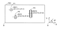
- FIG. 2 is an explanatory diagram for explaining the references REF1 to REF3 on the substrate PB1. In the figure, the corner of the substrate PB1 on the lower left side in the drawing is the origin 0. The right direction on the paper surface is taken as the X-axis direction, and the upward direction on the paper surface is taken as the Y-axis direction. Further, the rotation angle from the X axis with the origin 0 as the center is ⁇ .
- the mounting position on the board PB1 on which the component P1 is mounted is represented by a reference REF1.
- the mounting position of the component P1 can be represented by an X-axis direction position X11, a Y-axis direction position Y11, and a ⁇ -direction rotation angle ⁇ 11. That is, the reference REF1 specifies the mounting position of the component P1 on the board PB1.
- the references REF2 and REF3 are specified by the references REF2 and REF3.
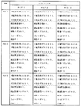
- FIG. 3 is an explanatory diagram illustrating an example of measurement information and production information.
- the figure shows an example of measurement information when the components P1 to P3 are mounted on the three substrates PB1 to PB3, respectively, and is an inspection result (measurement information) of the mounting inspection device 52.
- the X-axis direction shift XS11 of the component P1 on the board PB1 indicates a shift in the X-axis direction with respect to the normal X-axis direction position X11 of the component P1.
- the production information is at least one of equipment information of the board production line 1, raw material information supplied to the board production line 1, worker information for operating the board production line 1, and production procedure information of the board production line 1. It is preferable.
- the equipment information of the board production line 1 is information related to the production equipment of the board production line 1.
- the component mounter numbers M1 to M4 for identifying the component mounter 3 for identifying the component mounter 3, the component mount head numbers H1 to H4 for identifying the component mount heads for mounting the components P1 to P3, and the components P1 to P3 are sucked.
- suction nozzle numbers N1 to N6 for identifying suction nozzles to be performed, feeder numbers F1 to F4 for identifying feeders for supplying the components P1 and P2, and a tray number PT1 for identifying the tray unit for supplying the component P3 are included.
- Examples of the raw material information supplied to the board production line 1 include a part number for identifying the parts P1 to P3, a part lot number for identifying the production lot of the parts P1 to P3, and a part manufacturer number for identifying the part manufacturer.
- the worker information for operating the substrate production line 1 includes, for example, the name, age, affiliation, and the like of the worker.
- the production procedure information of the board production line 1 includes, for example, the mounting order of the components P1 to P3, and the setting of conditions such as positive pressure and negative pressure conditions when mounting the components.
- the component mounting machine number component mounting machine M1
- the component mounting head number component mounting head H1
- the suction nozzle number suction nozzle N1
- the feeder number A feeder F1
- a part number part P1
- the production information includes equipment information of the board production line 1, raw material information supplied to the board production line 1, worker information for operating the board production line 1, and production procedure information of the board production line 1. At least one. Therefore, it is possible to easily grasp the cause of the production failure in the substrate production line 1 and to extract the cause of the failure in the substrate production line 1 without omission.
- the production information is tabulated for each reference REF1 to REF3, and stored in the memory of the host computer. In addition to the above production information, various information related to production can be used as production information.
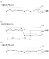
- FIG. 4 is a waveform diagram showing the change over time in the deviation in the X-axis direction of the parts P1 to P3, where (a) shows the reference REF1, (b) shows the reference REF2, and (c) shows the reference REF3. Indicates.
- the X-axis direction deviation XS1 of the component P1 when the component P1 is mounted on the substrates PB1 to PB3 is plotted in the mounting order. The same applies to the X axis direction deviation XS2 of the part P2 and the X axis direction deviation XS3 of the part P3, and the same applies to other measurement information.
- the change with time of the deviation XS1 in the X-axis direction of the component P1 in the reference REF1 is indicated by a curve L1.
- the standard upper limit value of the X-axis direction deviation XS1 is indicated by a straight line LT1
- the standard lower limit value of the X-axis direction deviation XS1 is indicated by a straight line LB1.
- the X-axis direction deviation XS1 (curve L1) of the component P1 in the reference REF1 is within the standard range indicated by the straight lines LT1 and LB1. Therefore, there is no sign of production failure for the reference REF1.
- the reference REF3 ((c) in the figure) the same applies to the reference REF3 ((c) in the figure).
- the X axis direction deviation XS2 (curve L2) of the component P2 in the reference REF2 becomes smaller than the standard lower limit value indicated by the straight line LB2 from time T1 to time T2, and after time T2. Even that state continues. That is, after time T2, there is a sign of production failure for the reference REF2.
- FIG. 5 is a flowchart showing an example of a procedure for detecting a sign of production failure.
- step S1 measurement information is collected for each of the references REF1 to REF3.
- step S2 a process capability index or a production failure occurrence rate is calculated from the measurement information.
- step S3 it is determined whether or not the process capability index or the production failure rate is within a standard range.
- step S4 the production failure determination flag is turned OFF, and this routine is ended once.
- step S5 the production failure determination flag is turned ON, and this routine is ended once.
- the process capability index is a numerical value of the ability to produce products (substrates PB1 to PB3) that satisfy quality standards. Specifically, the process capability index is calculated by dividing the required standard width by 6 ⁇ (six times ⁇ ). However, ⁇ is a standard deviation, and the standard width is calculated by subtracting the standard lower limit value from the standard upper limit value.
- the standard upper limit value and the standard lower limit value are determined in advance in consideration of the characteristics of production information, and are stored in the memory of the host computer.
- the defect sign detection unit 61 calculates a process capability index every elapse of a predetermined time.
- the failure sign detection unit 61 determines that the process capability index is within the standard range when the calculated value of the process capability index is within the predetermined range.
- the defect sign detection unit 61 determines that the process capability index is outside the standard range.
- the process capability index CP1 is calculated based on the five pieces of measurement information (X-axis direction deviation XS2 of the part P2) of the first sampling time SP1.
- the process capability index CP2 is calculated based on the five pieces of measurement information (X-axis direction deviation XS2 of the component P2) of the second sampling time SP2. Since the five pieces of measurement information of the second sampling time SP2 have a large variation in the measurement information as compared with the five pieces of measurement information of the first sampling time SP1, the process capability index CP2 is smaller than the process capability index CP1. Become.
- the process capability index CP2 when the process capability index CP2 is 1.2, it is outside a predetermined range (for example, 1.33 to 1.67), so the failure sign detection unit 61 determines that the process capability index is out of the standard range. .
- the process capability index CP1 is assumed to be within a predetermined range (eg, 1.33 to 1.67).
- the process capability index is calculated by dividing the required standard width by 3 ⁇ (3 times ⁇ ).
- the standard width is calculated by subtracting the average value of measurement information from the standard upper limit value.
- the standard width is calculated by subtracting the standard lower limit value from the average value of the measurement information.
- the production failure occurrence rate is used when the production state can be expressed by a discrete value such as a normal state where the production state is normal or an abnormal state where the production state is abnormal. Specifically, the production failure occurrence rate is a ratio in which the production state is abnormal among the number of productions in a predetermined period. The case where the occurrence rate of the production failure is calculated with respect to the presence or absence of the part P1 in the reference REF1 will be described as an example.
- the rate of production failure is 10%.
- the rate of production failure is 30%.
- the defect sign detection unit 61 calculates a production defect occurrence rate every elapse of a predetermined time.
- the failure sign detection unit 61 determines that the production failure occurrence rate is within the standard range when the production failure occurrence rate is smaller than a predetermined value.
- the failure sign detection unit 61 determines that the production failure occurrence rate is out of the standard range.
- the production failure occurrence rate is 30%, it is larger than a predetermined value (for example, 20%), so the failure sign detection unit 61 determines that the production failure occurrence rate is out of the standard range.
- the production failure occurrence rate is 10%, it is smaller than a predetermined value (for example, 20%), so the failure sign detection unit 61 determines that the production failure occurrence rate is within the standard range.
- the defect sign detection unit 61 detects a sign of production failure based on the process capability index calculated from the measurement information or the production failure occurrence rate. Therefore, it is easy to quantify the production quality, and the defect sign detection unit 61 can easily determine whether or not the production quality is within the standard range. And the defect sign detection part 61 can detect the sign of a production defect quantitatively.
- the defect sign detection unit 61 collects measurement information measured by the inspection device 5 for each of the references REF1 to REF3 that specify mounting positions on the substrates PB1 to PB3, which are products, and stores the measurement information of the references REF1 to REF3. Detect signs of production failure from changes over time. Therefore, it is easy to specify the reference REF2 related to the production failure, and it is easy to extract the measurement information in the specified reference REF2 and the production information related to the specified reference REF2.
- the failure cause identifying unit 62 performs a stratified analysis based on the production information related to the reference REF2 when the failure sign detection unit 61 detects a sign of production failure, and identifies the cause of the production failure from the analysis result.
- the defect sign detection unit 61 turns on the production defect determination flag when it detects a sign of production defect for the reference REF2. For the references REF1 and REF3, since no sign of production failure is seen, the failure sign detection unit 61 turns off the production failure determination flag.
- the failure cause identifying unit 62 performs stratified analysis based on the production information related to the reference REF2 in which the production failure determination flag is ON.
- Production information is generally a plurality of items (types, for example, component mounter 3, component mounting head, suction nozzle, feeder, etc.), and a plurality of pieces of information (for example, component mounter 3 for component mounters M1 to M1). 4 of M4).
- the component mounting machine 3 uses the component mounting machine M1
- the component mounting head uses the component mounting head H1.
- the suction nozzle uses the suction nozzle N2
- the feeder uses the feeder F2.
- production information related to one reference REF2 is limited to one piece of information per item (type). Therefore, the failure cause identifying unit 62 has one piece of production information (in this case, the component mounting machine M1 and the component mounting head) for each item (type) of the production information related to the reference REF2 when the sign of production failure is detected.
- the analysis target can be limited to H1, the suction nozzle N2, and the feeder F2). Therefore, the production line monitoring device 6 can reduce the data amount and the calculation amount of the analysis data compared to the case where all production information is analyzed, and real-time processing is easy.
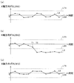
- FIGS. 6A and 6B are waveform diagrams showing a change with time in the deviation in the X-axis direction in the reference REF2, wherein FIG. 6A shows the component mounting head H1, FIG. 6B shows the suction nozzle N2, and FIG. 6C shows the feeder. F2 is shown.
- FIG. 6A shows the component mounting head H1
- FIG. 6B shows the suction nozzle N2
- FIG. 6C shows the feeder.
- F2 is shown.
- the X-axis direction deviation XS2 of the component P2 when the component P2 is mounted on the substrates PB1 to PB3 is plotted in the mounting order for each production information related to the reference REF2.
- the X-axis direction deviation XH1 of the component P2 (hereinafter referred to as the X-axis direction deviation XH1 of the component mounting head H1) when the component P2 is mounted on the substrates PB1 and PB3 using the component mounting head H1 is a curve. This is indicated by L4. Further, the standard upper limit value of the X axis direction deviation XH1 is indicated by a straight line LT4, and the standard lower limit value of the X axis direction deviation XH1 is indicated by a straight line LB4. The same applies to the suction nozzle N2 and the feeder F2.
- the X-axis direction deviation XH1 (curve L4) of the component mounting head H1 is within the standard range indicated by the straight lines LT4 and LB4. Therefore, it is considered that the component mounting head H1 is not a cause of production failure.
- the feeder F2 ((c) in the figure).
- the X-axis direction deviation XN2 of the suction nozzle N2 becomes smaller than the standard lower limit value indicated by the straight line LB5 from time T1 to time T2, and the state continues after time T2. is doing. That is, it is considered that the suction nozzle N2 is a cause of production failure.
- the failure cause identifying unit 62 determines that the sign of production failure for the reference REF2 is caused by the suction nozzle N2.
- the specific procedure for identifying the cause of production failure is the same as the procedure for detecting signs of production failure, and the cause of production failure can be identified based on the process capability index or the incidence of production failure. it can.
- the failure cause identifying unit 62 performs a stratified analysis based on the production information related to the reference REF2 when the failure sign detection unit 61 detects a sign of production failure, and determines the production failure from the analysis result. specify a reason. Therefore, the defect cause identifying unit 62 identifies the cause of the production defect with higher accuracy than when analyzing the cause of the defect based on the occurrence probability calculated in advance or when specifying and limiting the analysis target in advance. be able to.
- the failure handling determination unit 63 determines a handling content for a production failure.
- the countermeasure contents and the priority order of countermeasures are stored in advance in the memory of the host computer.
- the failure handling determination unit 63 refers to the memory of the host computer and acquires the content of handling for the cause of the production failure identified by the failure cause identifying unit 62. If there are multiple causes of production failure, the priority order of countermeasures is also acquired.
- the failure handling determination unit 63 determines whether or not the worker needs to deal with the production failure.
- the case where the worker needs to deal with the production failure is called worker handling, and the case where the worker does not need to deal with the production failure is called automatic handling.
- the failure handling determination unit 63 transmits a handling signal to the failure handling instruction unit 64.
- the defect countermeasure determination unit 63 transmits a countermeasure signal to the solder printer 2, the component mounter 3, or the reflow machine 4.
- the solder printer 2, the component mounter 3 or the reflow machine 4 receives the countermeasure signal
- the solder printer 2, the component mounter 3 or the reflow machine 4 deals with the production failure based on the received countermeasure content.
- the failure handling determination unit 63 instructs the component mounter 3 to switch the suction nozzle N2.
- the component mounter 3 receives an instruction to switch the suction nozzle N2 from the failure handling determination unit 63, the component mounter 3 switches the suction nozzle N2 to a normal suction nozzle.
- the failure handling instruction unit 64 When the failure handling instruction unit 64 receives the handling signal from the failure handling determination unit 63, the failure handling instruction unit 64 displays the handling content and the handling priority order on the monitor 7. The worker deals with the production failure according to the contents of countermeasures displayed on the monitor 7 and the priority order of the countermeasures. For example, let us consider a case where the component mounting head H1 (priority is first) and feeder F2 (priority is second) are the cause of production failure.
- the defect handling instruction unit 64 displays on the monitor 7 that the component mounting head H1 and the feeder F2 are the cause of the production failure and needs to be replaced with normal products in the order of the component mounting head H1 and the feeder F2. To arouse. The operator replaces the component mounting head H1 and the feeder F2 in order of the component mounting head H1 and the feeder F2 in accordance with the contents displayed on the monitor 7.
- the board production line 1 since a sign of a production failure in the board production line 1 can be detected, it is possible to deal with the production failure before the production failure actually occurs in the board production line 1, and board production.
- the operating rate of the line 1 can be improved.
- the present invention is not limited to the embodiments described above and shown in the drawings, and can be implemented with appropriate modifications within a range not departing from the gist.
- the present invention is not limited to detecting a sign of production failure in the production line, but can also be applied to cases where production failure is actually detected in the production line (for example, a missing part).
Landscapes
- Engineering & Computer Science (AREA)
- Manufacturing & Machinery (AREA)
- Quality & Reliability (AREA)
- Physics & Mathematics (AREA)
- General Physics & Mathematics (AREA)
- Automation & Control Theory (AREA)
- General Engineering & Computer Science (AREA)
- Operations Research (AREA)
- Microelectronics & Electronic Packaging (AREA)
- Supply And Installment Of Electrical Components (AREA)
- General Factory Administration (AREA)
- Electric Connection Of Electric Components To Printed Circuits (AREA)
Abstract
Description
本実施形態では、生産ラインの一例として、多数の部品が実装される基板を生産する基板生産ライン1について説明する。なお、説明の都合上、3枚の基板PB1~PB3に3つの部品P1~P3をそれぞれ実装する基板生産ライン1について説明するが、基板数および部品数は、これらに限定されるものではない。また、生産ラインは、基板生産ライン1に限定されるものではなく、例えば、工作機械や自動車の生産ラインなど種々の生産ラインに適用することができる。
生産ライン監視装置6は、ホストコンピュータ内に設けられ、基板生産ライン1における生産不良の兆候を検出して、生産不良の原因を特定する。ホストコンピュータは、CPUおよびメモリを有しており、メモリに記憶されているプログラムを実行することによって、生産ライン監視装置6を駆動させることができる。図1に示すように、生産ライン監視装置6は、制御ブロックとして捉えると、不良兆候検出部61、不良原因特定部62、不良対処判定部63および不良対処指示部64を備えている。
不良兆候検出部61は、基板生産ライン1における生産不良の兆候を検出する。まず、不良兆候検出部61は、基板PB1における実装位置を特定するリファレンスREF1~REF3毎に測定情報を収集する。基板PB2、PB3についても同様である。図2は、基板PB1におけるリファレンスREF1~REF3を説明する説明図である。同図では、紙面左方向下側の基板PB1の角部を原点0とする。そして、紙面右方向をX軸方向とし、紙面上方向をY軸方向とする。また、原点0を中心とするX軸からの回転角をθとする。
不良原因特定部62は、不良兆候検出部61が生産不良の兆候を検出した際のリファレンスREF2に関係する生産情報に基づいて層別分析を行い、当該分析結果から生産不良の原因を特定する。不良兆候検出部61は、リファレンスREF2について生産不良の兆候を検出すると、生産不良判定フラグをONにする。リファレンスREF1、REF3については、生産不良の兆候が見られないので、不良兆候検出部61は、生産不良判定フラグをOFFにする。不良原因特定部62は、生産不良判定フラグがONであるリファレンスREF2に関係する生産情報に基づいて層別分析を行う。
不良対処判定部63は、生産不良に対する対処内容を判定する。対処内容および対処の優先順位は、予めホストコンピュータのメモリに記憶されている。不良対処判定部63は、ホストコンピュータのメモリを参照して、不良原因特定部62が特定した生産不良の原因に対する対処内容を取得する。生産不良の原因が複数ある場合は、対処の優先順位も併せて取得する。
不良対処指示部64は、不良対処判定部63から対処信号を受信すると、モニタ7に対処内容および対処の優先順位を表示する。作業者は、モニタ7に表示される対処内容および対処の優先順位に従って、生産不良に対する対処を行う。例えば、部品装着ヘッドH1(優先順位は1番とする)およびフィーダF2(優先順位は2番とする)が生産不良の原因である場合を考える。不良対処指示部64は、部品装着ヘッドH1およびフィーダF2が生産不良の原因であり、部品装着ヘッドH1、フィーダF2の順に正常品に交換する必要がある旨をモニタ7に表示して、作業者に喚起する。作業者は、モニタ7に表示される内容に従って、部品装着ヘッドH1、フィーダF2の順に正常な部品装着ヘッドH1、フィーダF2と交換する。
本発明は上記し且つ図面に示した実施形態のみに限定されるものではなく、要旨を逸脱しない範囲内で適宜変更して実施することができる。例えば、本発明は、生産ラインにおける生産不良の兆候を検出する場合に限られず、実際に生産ラインにおいて生産不良を検出した場合(例えば、部品の欠品など)にも適用することができる。
2:はんだ印刷機、
3:部品実装機、
4:リフロー機、
5:検査装置、
6:生産ライン監視装置、
61:不良兆候検出部、
62:不良原因特定部
Claims (4)
- 生産ラインにおける生産不良の兆候を検出する不良兆候検出部と、前記生産不良の原因を特定する不良原因特定部と、を備える生産ライン監視装置であって、
前記不良兆候検出部は、製品における位置を特定するリファレンス毎に検査装置によって測定された測定情報を収集して、前記リファレンスにおける測定情報の経時変化から前記生産不良の兆候を検出し、
前記不良原因特定部は、前記不良兆候検出部が前記生産不良の兆候を検出した際の前記リファレンスに関係する生産情報に基づいて層別分析を行い、当該分析結果から前記生産不良の原因を特定する生産ライン監視装置。 - 前記生産情報は、前記生産ラインの設備情報、前記生産ラインに供給される原材料情報、前記生産ラインを操作する作業者情報および前記生産ラインの生産手順情報のうちの少なくとも1つである請求項1に記載の生産ライン監視装置。
- 前記不良兆候検出部は、前記測定情報から算出される工程能力指数または前記生産不良の発生率に基づいて、前記生産不良の兆候を検出する請求項1または2に記載の生産ライン監視装置。
- 前記生産ラインは、基板上にはんだペーストを印刷するはんだ印刷機と、部品を前記基板に実装する部品実装機と、前記基板に実装された前記部品をはんだ付けするリフロー機と、を備える基板生産ラインであって、
前記検査装置は、前記基板生産ラインの途中に設けられている請求項1~3のいずれか一項に記載の生産ライン監視装置。
Priority Applications (5)
| Application Number | Priority Date | Filing Date | Title |
|---|---|---|---|
| EP12885868.5A EP2902861B1 (en) | 2012-09-28 | 2012-09-28 | Production line monitoring device |
| PCT/JP2012/075239 WO2014049872A1 (ja) | 2012-09-28 | 2012-09-28 | 生産ライン監視装置 |
| JP2014538065A JP5959656B2 (ja) | 2012-09-28 | 2012-09-28 | 生産ライン監視装置 |
| US14/425,424 US9818236B2 (en) | 2012-09-28 | 2012-09-28 | Production line monitoring device |
| CN201280076090.1A CN104685429B (zh) | 2012-09-28 | 2012-09-28 | 生产线监视装置 |
Applications Claiming Priority (1)
| Application Number | Priority Date | Filing Date | Title |
|---|---|---|---|
| PCT/JP2012/075239 WO2014049872A1 (ja) | 2012-09-28 | 2012-09-28 | 生産ライン監視装置 |
Publications (1)
| Publication Number | Publication Date |
|---|---|
| WO2014049872A1 true WO2014049872A1 (ja) | 2014-04-03 |
Family
ID=50387330
Family Applications (1)
| Application Number | Title | Priority Date | Filing Date |
|---|---|---|---|
| PCT/JP2012/075239 Ceased WO2014049872A1 (ja) | 2012-09-28 | 2012-09-28 | 生産ライン監視装置 |
Country Status (5)
| Country | Link |
|---|---|
| US (1) | US9818236B2 (ja) |
| EP (1) | EP2902861B1 (ja) |
| JP (1) | JP5959656B2 (ja) |
| CN (1) | CN104685429B (ja) |
| WO (1) | WO2014049872A1 (ja) |
Cited By (5)
| Publication number | Priority date | Publication date | Assignee | Title |
|---|---|---|---|---|
| CN105491872A (zh) * | 2014-09-19 | 2016-04-13 | 富士机械制造株式会社 | 监视工业产品的生产装置的系统 |
| JPWO2018142532A1 (ja) * | 2017-02-02 | 2019-11-07 | 株式会社Fuji | 生産管理装置 |
| KR20200002000A (ko) * | 2018-06-28 | 2020-01-07 | 주식회사 고영테크놀러지 | 기판에 실장된 부품의 실장 불량 원인을 결정하는 전자 장치 및 방법 |
| JP2021012979A (ja) * | 2019-07-09 | 2021-02-04 | パナソニックIpマネジメント株式会社 | 実装基板製造システムおよび実装基板製造方法 |
| US11428644B2 (en) | 2018-11-27 | 2022-08-30 | Koh Young Technology Inc. | Method and electronic apparatus for displaying inspection result of board |
Families Citing this family (22)
| Publication number | Priority date | Publication date | Assignee | Title |
|---|---|---|---|---|
| CN104798457B (zh) * | 2012-11-19 | 2017-10-24 | 松下知识产权经营株式会社 | 电子元件安装系统及电子元件安装方法 |
| JP5945697B2 (ja) * | 2012-11-19 | 2016-07-05 | パナソニックIpマネジメント株式会社 | 電子部品実装システムおよび電子部品実装方法 |
| WO2014076969A1 (ja) * | 2012-11-19 | 2014-05-22 | パナソニック株式会社 | 電子部品実装システムおよび電子部品実装方法 |
| US11134597B2 (en) | 2015-10-14 | 2021-09-28 | Yamaha Hatsudoki Kabushiki Kaisha | Component mounting device |
| JP6828300B2 (ja) * | 2015-11-16 | 2021-02-10 | 株式会社ジェイテクト | 異常解析システム及び解析装置 |
| JP6922168B2 (ja) * | 2016-08-10 | 2021-08-18 | オムロン株式会社 | 表面実装ラインの品質管理システム及びその制御方法 |
| JP6530779B2 (ja) * | 2017-04-20 | 2019-06-12 | ファナック株式会社 | 加工不良要因推定装置 |
| GB201708730D0 (en) | 2017-06-01 | 2017-07-19 | Renishaw Plc | Production and measurement of work workpieces |
| EP3661343B1 (en) * | 2017-07-25 | 2024-02-14 | Fuji Corporation | Substrate processing management system |
| CN114449886B (zh) * | 2018-06-28 | 2024-05-14 | 株式会社高迎科技 | 确定贴装在基板部件的贴装不合格原因的电子装置及方法 |
| JP6977686B2 (ja) * | 2018-08-06 | 2021-12-08 | オムロン株式会社 | 制御システムおよび制御装置 |
| KR102264677B1 (ko) * | 2018-11-27 | 2021-06-15 | 주식회사 고영테크놀러지 | 기판에 대한 검사 결과를 표시하는 전자 장치 및 방법 |
| TW202026096A (zh) * | 2019-01-02 | 2020-07-16 | 財團法人工業技術研究院 | 刀具壽命預測系統及其方法 |
| DE102019201557A1 (de) * | 2019-02-07 | 2020-08-13 | Zf Friedrichshafen Ag | Verfahren und Vorrichtung zum automatisierten Identifizieren eines Produktfehlers eines Produkts und/oder zum automatisierten Identifizieren einer Produktfehlerursache des Produktfehlers |
| CN109976287A (zh) * | 2019-04-25 | 2019-07-05 | 伟创力电子设备(深圳)有限公司 | Pcba预测制造控制方法、装置及电子设备 |
| CN110031042A (zh) * | 2019-04-25 | 2019-07-19 | 伟创力电子设备(深圳)有限公司 | Pcba制造的三段式检测方法及装置 |
| US20220404818A1 (en) * | 2021-02-26 | 2022-12-22 | Ball Corporation | Apparatus and method of engraving machine readable information on a metallic workpiece during manufacturing and tracking systems related thereto |
| WO2022183054A1 (en) | 2021-02-26 | 2022-09-01 | Ball Corporation | Container with mark or markings for tracking and tracing |
| US11598801B2 (en) * | 2021-08-02 | 2023-03-07 | Arch Systems Inc. | Method for manufacturing system analysis and/or maintenance |
| EP4573423A1 (en) * | 2022-08-18 | 2025-06-25 | Carl Zeiss AG | Method and manufacturing installation for producing a plurality of workpieces |
| CN115808911B (zh) * | 2023-02-02 | 2023-04-28 | 成都秦川物联网科技股份有限公司 | 用于生产线产生不良品时的工业物联网调控方法及系统 |
| CN117784729A (zh) * | 2023-12-22 | 2024-03-29 | 青岛奥利普奇智智能工业技术有限公司 | 产线中的校验方法、装置、设备及存储介质 |
Citations (4)
| Publication number | Priority date | Publication date | Assignee | Title |
|---|---|---|---|---|
| JP3511632B2 (ja) | 1992-12-24 | 2004-03-29 | 松下電器産業株式会社 | 実装工程不良要因分析方法 |
| JP2005173911A (ja) * | 2003-12-10 | 2005-06-30 | Trecenti Technologies Inc | 工程管理システムおよび工程管理方法 |
| JP2005353750A (ja) * | 2004-06-09 | 2005-12-22 | Juki Corp | 電子部品搭載装置の保守管理装置 |
| JP2010177293A (ja) * | 2009-01-27 | 2010-08-12 | Omron Corp | 部品実装基板の品質管理用の情報表示システムおよび情報表示方法 |
Family Cites Families (9)
| Publication number | Priority date | Publication date | Assignee | Title |
|---|---|---|---|---|
| US6845278B2 (en) | 2002-08-07 | 2005-01-18 | Kimberly-Clark Worldwide, Inc. | Product attribute data mining in connection with a web converting manufacturing process |
| US20040199361A1 (en) | 2003-04-01 | 2004-10-07 | Ching-Shan Lu | Method and apparatus for equipment diagnostics and recovery with self-learning |
| JP2006343952A (ja) * | 2005-06-08 | 2006-12-21 | Fujitsu Ltd | 製造管理装置、製造管理方法および製造管理プログラム |
| JP3786137B1 (ja) * | 2005-08-25 | 2006-06-14 | オムロン株式会社 | 情報処理装置、情報処理方法、プログラム、および、プログラムを記録したコンピュータ読み取り可能な記録媒体 |
| JP4855464B2 (ja) * | 2006-04-25 | 2012-01-18 | シャープ株式会社 | 不良原因設備特定システム |
| JP5017943B2 (ja) * | 2006-07-04 | 2012-09-05 | オムロン株式会社 | 不良分析支援装置、不良分析支援用プログラム、および、不良分析支援用プログラムを記録した記録媒体 |
| CN102194655B (zh) * | 2010-03-15 | 2013-04-10 | 中芯国际集成电路制造(上海)有限公司 | 半导体工艺机台参数优化调整的方法 |
| US9069352B2 (en) * | 2010-12-17 | 2015-06-30 | JDT Processwork Inc. | Automated fault analysis and response system |
| DE102010063796A1 (de) * | 2010-12-21 | 2012-06-21 | Asm Assembly Systems Gmbh & Co. Kg | Verfahren zur positionsspezifischen Fehleranalyse von bestückten Substraten |
-
2012
- 2012-09-28 WO PCT/JP2012/075239 patent/WO2014049872A1/ja not_active Ceased
- 2012-09-28 EP EP12885868.5A patent/EP2902861B1/en active Active
- 2012-09-28 JP JP2014538065A patent/JP5959656B2/ja active Active
- 2012-09-28 CN CN201280076090.1A patent/CN104685429B/zh active Active
- 2012-09-28 US US14/425,424 patent/US9818236B2/en active Active
Patent Citations (4)
| Publication number | Priority date | Publication date | Assignee | Title |
|---|---|---|---|---|
| JP3511632B2 (ja) | 1992-12-24 | 2004-03-29 | 松下電器産業株式会社 | 実装工程不良要因分析方法 |
| JP2005173911A (ja) * | 2003-12-10 | 2005-06-30 | Trecenti Technologies Inc | 工程管理システムおよび工程管理方法 |
| JP2005353750A (ja) * | 2004-06-09 | 2005-12-22 | Juki Corp | 電子部品搭載装置の保守管理装置 |
| JP2010177293A (ja) * | 2009-01-27 | 2010-08-12 | Omron Corp | 部品実装基板の品質管理用の情報表示システムおよび情報表示方法 |
Non-Patent Citations (1)
| Title |
|---|
| See also references of EP2902861A4 |
Cited By (8)
| Publication number | Priority date | Publication date | Assignee | Title |
|---|---|---|---|---|
| CN105491872A (zh) * | 2014-09-19 | 2016-04-13 | 富士机械制造株式会社 | 监视工业产品的生产装置的系统 |
| JPWO2018142532A1 (ja) * | 2017-02-02 | 2019-11-07 | 株式会社Fuji | 生産管理装置 |
| KR20200002000A (ko) * | 2018-06-28 | 2020-01-07 | 주식회사 고영테크놀러지 | 기판에 실장된 부품의 실장 불량 원인을 결정하는 전자 장치 및 방법 |
| KR102267919B1 (ko) * | 2018-06-28 | 2021-06-23 | 주식회사 고영테크놀러지 | 기판에 실장된 부품의 실장 불량 원인을 결정하는 전자 장치 및 방법 |
| US11395450B2 (en) | 2018-06-28 | 2022-07-19 | Koh Young Technology Inc. | Electronic apparatus and method for determining cause of mounting failure for component mounted on substrate |
| US11428644B2 (en) | 2018-11-27 | 2022-08-30 | Koh Young Technology Inc. | Method and electronic apparatus for displaying inspection result of board |
| JP2021012979A (ja) * | 2019-07-09 | 2021-02-04 | パナソニックIpマネジメント株式会社 | 実装基板製造システムおよび実装基板製造方法 |
| JP7369905B2 (ja) | 2019-07-09 | 2023-10-27 | パナソニックIpマネジメント株式会社 | 実装基板製造システムおよび実装基板製造方法 |
Also Published As
| Publication number | Publication date |
|---|---|
| EP2902861A1 (en) | 2015-08-05 |
| EP2902861B1 (en) | 2020-11-18 |
| CN104685429B (zh) | 2017-12-08 |
| US20150243108A1 (en) | 2015-08-27 |
| JPWO2014049872A1 (ja) | 2016-08-22 |
| EP2902861A4 (en) | 2016-07-13 |
| CN104685429A (zh) | 2015-06-03 |
| JP5959656B2 (ja) | 2016-08-02 |
| US9818236B2 (en) | 2017-11-14 |
Similar Documents
| Publication | Publication Date | Title |
|---|---|---|
| JP5959656B2 (ja) | 生産ライン監視装置 | |
| JP4767995B2 (ja) | 部品実装方法、部品実装機、実装条件決定方法、実装条件決定装置およびプログラム | |
| US8849442B2 (en) | Component mounting line and component mounting method | |
| JP5820424B2 (ja) | 半田印刷検査装置 | |
| US11259451B2 (en) | Production management device | |
| JP4700653B2 (ja) | 実装ライン、実装基板の検査装置および検査方法 | |
| EP3499330A1 (en) | Management system, management device, management method, and program | |
| KR20160017659A (ko) | 기판 검사방법 및 이를 이용한 기판 검사시스템 | |
| KR101451690B1 (ko) | 부품 실장 시스템, 부품 실장 장치 및 부품 검사 장치 | |
| CN105940354A (zh) | 品质管理装置及其控制方法 | |
| EP3661343B1 (en) | Substrate processing management system | |
| JP4481192B2 (ja) | 検査条件管理システムおよび部品実装システム | |
| JP4871234B2 (ja) | 部品実装装置の異常検出方法及び装置 | |
| JP5980944B2 (ja) | 部品実装ラインの生産監視システム及び生産監視方法 | |
| JP2020043159A (ja) | 実装システム、および生産管理装置 | |
| JP7473735B2 (ja) | 異物検出装置および異物検出方法 | |
| JP7484744B2 (ja) | 管理システム、管理装置、管理方法、及びプログラム | |
| JP2005228949A (ja) | 検査装置、検査システム及び検査方法 | |
| JPH08204399A (ja) | 実装基板生産システム | |
| JP5818524B2 (ja) | 検査装置および検査システム | |
| US20230217637A1 (en) | Component mounting system | |
| KR20110060997A (ko) | 프린팅 공정의 불량 분석 방법 및 이러한 방법이 프로그래밍되어 저장된 컴퓨터로 읽을 수 있는 저장매체 | |
| JP2007088500A (ja) | クリーム半田の印刷検査方法及び印刷検査装置並びに印刷装置とその方法 | |
| WO2018105014A1 (ja) | 基板作業システム | |
| KR20160088590A (ko) | 클로즈 루프 제어 시스템 |
Legal Events
| Date | Code | Title | Description |
|---|---|---|---|
| 121 | Ep: the epo has been informed by wipo that ep was designated in this application |
Ref document number: 12885868 Country of ref document: EP Kind code of ref document: A1 |
|
| ENP | Entry into the national phase |
Ref document number: 2014538065 Country of ref document: JP Kind code of ref document: A |
|
| WWE | Wipo information: entry into national phase |
Ref document number: 14425424 Country of ref document: US |
|
| NENP | Non-entry into the national phase |
Ref country code: DE |
|
| WWE | Wipo information: entry into national phase |
Ref document number: 2012885868 Country of ref document: EP |