WO2014050055A1 - 無線センサ装置 - Google Patents
無線センサ装置 Download PDFInfo
- Publication number
- WO2014050055A1 WO2014050055A1 PCT/JP2013/005578 JP2013005578W WO2014050055A1 WO 2014050055 A1 WO2014050055 A1 WO 2014050055A1 JP 2013005578 W JP2013005578 W JP 2013005578W WO 2014050055 A1 WO2014050055 A1 WO 2014050055A1
- Authority
- WO
- WIPO (PCT)
- Prior art keywords
- transmission
- signal
- circuit
- antenna
- transmission line
- Prior art date
- Legal status (The legal status is an assumption and is not a legal conclusion. Google has not performed a legal analysis and makes no representation as to the accuracy of the status listed.)
- Ceased
Links
Images


Classifications
-
- H—ELECTRICITY
- H04—ELECTRIC COMMUNICATION TECHNIQUE
- H04W—WIRELESS COMMUNICATION NETWORKS
- H04W24/00—Supervisory, monitoring or testing arrangements
- H04W24/10—Scheduling measurement reports ; Arrangements for measurement reports
-
- G—PHYSICS
- G01—MEASURING; TESTING
- G01S—RADIO DIRECTION-FINDING; RADIO NAVIGATION; DETERMINING DISTANCE OR VELOCITY BY USE OF RADIO WAVES; LOCATING OR PRESENCE-DETECTING BY USE OF THE REFLECTION OR RERADIATION OF RADIO WAVES; ANALOGOUS ARRANGEMENTS USING OTHER WAVES
- G01S13/00—Systems using the reflection or reradiation of radio waves, e.g. radar systems; Analogous systems using reflection or reradiation of waves whose nature or wavelength is irrelevant or unspecified
- G01S13/02—Systems using reflection of radio waves, e.g. primary radar systems; Analogous systems
- G01S13/50—Systems of measurement based on relative movement of target
- G01S13/52—Discriminating between fixed and moving objects or between objects moving at different speeds
- G01S13/56—Discriminating between fixed and moving objects or between objects moving at different speeds for presence detection
-
- G—PHYSICS
- G01—MEASURING; TESTING
- G01S—RADIO DIRECTION-FINDING; RADIO NAVIGATION; DETERMINING DISTANCE OR VELOCITY BY USE OF RADIO WAVES; LOCATING OR PRESENCE-DETECTING BY USE OF THE REFLECTION OR RERADIATION OF RADIO WAVES; ANALOGOUS ARRANGEMENTS USING OTHER WAVES
- G01S7/00—Details of systems according to groups G01S13/00, G01S15/00, G01S17/00
- G01S7/02—Details of systems according to groups G01S13/00, G01S15/00, G01S17/00 of systems according to group G01S13/00
- G01S7/03—Details of HF subsystems specially adapted therefor, e.g. common to transmitter and receiver
-
- G—PHYSICS
- G01—MEASURING; TESTING
- G01S—RADIO DIRECTION-FINDING; RADIO NAVIGATION; DETERMINING DISTANCE OR VELOCITY BY USE OF RADIO WAVES; LOCATING OR PRESENCE-DETECTING BY USE OF THE REFLECTION OR RERADIATION OF RADIO WAVES; ANALOGOUS ARRANGEMENTS USING OTHER WAVES
- G01S7/00—Details of systems according to groups G01S13/00, G01S15/00, G01S17/00
- G01S7/02—Details of systems according to groups G01S13/00, G01S15/00, G01S17/00 of systems according to group G01S13/00
- G01S7/28—Details of pulse systems
-
- H—ELECTRICITY
- H04—ELECTRIC COMMUNICATION TECHNIQUE
- H04W—WIRELESS COMMUNICATION NETWORKS
- H04W4/00—Services specially adapted for wireless communication networks; Facilities therefor
- H04W4/70—Services for machine-to-machine communication [M2M] or machine type communication [MTC]
-
- H—ELECTRICITY
- H04—ELECTRIC COMMUNICATION TECHNIQUE
- H04W—WIRELESS COMMUNICATION NETWORKS
- H04W64/00—Locating users or terminals or network equipment for network management purposes, e.g. mobility management
- H04W64/006—Locating users or terminals or network equipment for network management purposes, e.g. mobility management with additional information processing, e.g. for direction or speed determination
Definitions
- the present invention relates to a wireless sensor device, and more particularly, to a wireless sensor device capable of detecting a minute variation with high sensitivity.
- a wireless sensor device described in Patent Document 1 is known as a wireless sensor device that detects a detection target without contact.
- the wireless sensor device 900 includes a first and a second polarization antenna in which the polarization planes of the radiated waves are orthogonal to each other.
- An antenna ANT a first mixer circuit 914a connected to the first polarization antenna and receiving a first reception signal received by the first polarization antenna, and a second polarization antenna connected to the first A second mixer circuit 914b to which a second received signal received by the second polarization antenna is input, and the first and second mixer circuits 914a, 914a, A signal generation circuit 911 that generates a pulse signal supplied to 914b and a differential amplifier circuit 915 are provided.
- the first mixer circuit 914a mixes the first reception signal and the pulse signal
- the second mixer circuit 914b mixes the second reception signal and the pulse signal. Differentially amplifies the mixed output.
- the RF oscillation circuit 911 generates a pulse signal to be fed to the transmission / reception antenna ANT, distributes the pulse signal received from the RF oscillation circuit 911 by the distributor 912, and sends the pulse signal to the feeding points 913a and 913b of the transmission / reception antenna ANT. Part of the pulse signal sent to the feed points 913a and 913b of the transmission / reception antenna ANT is sent to the mixer circuits 914a and 914b, respectively.
- a radio wave radiated from the transmission / reception antenna ANT is reflected by the object O, and a reception signal obtained by receiving the reflected wave by the transmission / reception antenna ANT and a feeding point 913a of the transmission / reception antenna ANT are fed via the distributor 912.
- Part of the first pulse signal is input to the mixer circuit 914a, and part of the second pulse signal fed to the feeding point 913b of the transmission / reception antenna ANT is input to the mixer circuit 914b.
- the motion of the detection target is detected from the combined signal Vt of the transmission signal Vo and the reflected wave Vr.
- the relationship between the composite signal Vt, the transmission signal Vo, and the reflected wave Vr can be expressed as the following (Expression 1).
- Vt 2 Vo 2 + Vr 2 -2 ⁇ Vo ⁇ Vr ⁇ cos ⁇
- ⁇ is the phase shift angle (phase difference) of the reflected wave Vr with respect to the transmission signal Vo.
- the composite signal Vt is expressed by the following (Formula 2).
- the movement of the detection target is large, and the phase of the reflected signal reflected from the detection target when the transmission signal radiated toward the detection target changes greatly with respect to the transmission signal It is possible to detect the movement of the detection target without any problem.
- the detection sensitivity varies significantly depending on the distance between the wireless sensor device and the detection target.
- An object of the present invention is to solve the above-described problems and to provide a wireless sensor device that can detect a minute variation with high sensitivity while avoiding deterioration in sensitivity for detecting a motion of a detection target.
- the wireless sensor device in order to solve this problem, an antenna that radiates a transmission signal and receives a reflected signal reflected by a detection target of the transmission signal, and an output terminal connected to the antenna
- a transmission circuit that generates the transmission signal, and is connected to the output terminal of the transmission circuit, and is received by the antenna and a part of the transmission signal during transmission of the transmission signal from the transmission circuit
- a detection circuit that receives and detects the reflected signal
- a signal processing circuit that is connected to the detection circuit and processes a signal output from the detection circuit, and is connected to the transmission circuit and controls the transmission circuit
- the wireless sensor device is characterized in that the plurality of transmission lines are two transmission lines, and the line lengths of the two transmission lines are different from each other by 1/8 of the wavelength of the transmission signal.
- control circuit performs control so as to switch the plurality of transmission lines, and selects and switches a transmission line that maximizes a signal output from the signal processing circuit.
- the invention of claim 1 there are a plurality of transmission lines having different line lengths between the antenna and the output terminal, and switching means for switching the plurality of transmission lines to connect the antenna and the output terminal.
- the difference in the line length of the transmission line is less than one quarter of the wavelength of the transmission signal. For this reason, when the detection output decreases when the phase difference of the reflected wave with respect to the transmission output approaches the null point where the sensitivity decreases due to a change in the distance to the detection target, etc., transmission lines with different line lengths are selected. By switching between the two, the phase difference can be changed, and the minute variation can be detected with high sensitivity by avoiding the deterioration of the sensitivity for detecting the motion of the detection target.
- the transmission signal output to the output terminal of the transmission circuit and the transmission signal are reflected by the detection target.
- the phase difference until the reflected signal is returned to the output terminal differs by ⁇ / 2 (rad) by switching the transmission line. Can work in good condition.
- control circuit since the control circuit controls to switch a plurality of transmission lines, and selects and switches the transmission line that maximizes the signal output from the signal processing circuit, a more sensitive state Can detect the motion of the detection target.
- a wireless sensor device capable of detecting a minute mutation with high sensitivity while avoiding deterioration of sensitivity for detecting a motion of a detection target.
- the wireless sensor device 100 detects a detection target by radiating a transmission signal to the detection target and detecting the reflected signal.
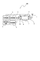
- FIG. 2 is a block diagram illustrating a configuration of the wireless sensor device 100.
- the wireless sensor device 100 includes an antenna 1, a transmission circuit 2 having an output terminal 2a, a detection circuit 3, a signal processing circuit 4, a control circuit 5, a first transmission line 6, and a first transmission line. Two transmission lines 7, a first switch 8, and a second switch 9 are provided.
- the wireless sensor device 100 has a power supply circuit (not shown) and supplies power necessary for operation to each part of the wireless sensor device 100.
- the antenna 1 is connected to the second switch 9, and the second switch 9 serves as a switching means so that one of the first transmission line 6 and the second transmission line 7 can be selected and connected to the antenna 1. One ends of the transmission line 6 and the second transmission line 7 are connected.
- a switch 8 is connected, and the first switch 8 is connected to the output terminal 2 a of the transmission circuit 2.
- the transmission circuit 2 performs a transmission operation of generating a transmission signal and outputting the transmission signal to the output terminal 2a.
- the detection circuit 3 is connected to the output terminal 2a of the transmission circuit 2, and a part of the transmission signal output from the output terminal 2a and the reflected signal received by the antenna 1 are transmitted during the transmission operation of the transmission circuit 2. A part of the input transmission signal input to the detection circuit 3 and the reflected signal received by the antenna 1 are detected.
- the signal processing circuit 4 is connected to the detection circuit 3, performs signal processing of the detection output signal output from the detection circuit 3, and outputs the result to the control circuit 5.
- the control circuit 5 is connected to the transmission circuit 2, the signal processing circuit 4, the first switch 8, and the second switch 9.
- the control circuit 5 controls the operation state of the transmission circuit 2 and obtains an output signal from the signal processing circuit 4 to detect and detect body movements associated with breathing to be detected and body surface movements associated with heartbeats. Judgment of presence or absence is performed.
- control circuit 5 controls the first switch 8 and the second switch 9, selects either the first transmission line 6 or the second transmission line 7, and connects the antenna 1 and the output terminal 2a. Outputs the control signal to be connected.
- the first transmission line 6 is a transmission line having a characteristic impedance substantially equal to the output impedance of the transmission circuit 2 and the impedance of the antenna 1 at the frequency of the transmission signal generated by the transmission circuit 2 and having a line length of Le.
- the second transmission line 7 has a characteristic impedance substantially equal to the output impedance of the transmission circuit 2 and the impedance of the antenna 1 at the frequency of the transmission signal generated by the transmission circuit 2, and when one wavelength of the transmission signal is ⁇ , This is a transmission line having a line length of Le + ⁇ / 8, which is longer by one-eighth of the wavelength of the transmission signal than the line length Le of one transmission line 6.
- the transmission line length means that the transmission speed is slower than that in vacuum when the transmission signal propagates through the transmission line (the distance traveled is shorter). It is expressed using the wavelength or phase shift angle of the transmitted transmission signal.
- the wavelength of the transmission signal described above indicates the wavelength on the transmission line, and one-eighth of the wavelength is a length that is ⁇ / 4 (rad) phase delay in phase shift angle.
- the control circuit 5 controls the first switch 8 and the second switch 9 and selects the first transmission line 6, the transmission signal output from the output terminal 2a of the transmission circuit 2 is the first switch. 8, and radiated from the antenna 1 through the first transmission line 6 and the second switch 9.
- the transmission signal radiated from the antenna 1 is reflected by the detection target and received by the antenna 1 as a reflected signal.
- the reflected signal received by the antenna 1 returns to the output terminal 2a through the second switch 9, the first transmission line 6, and the first switch 8, and a part of the transmission signal and the reflected signal are input to the detection circuit 3. Is detected.
- the length of the path from the output terminal 2 a to the antenna is represented by the line length Le of the first transmission line 6 when the length of the path of the first switch 8 and the second switch 9 can be ignored.
- the control circuit 5 controls the first switch 8 and the second switch 9 and selects the second transmission line 7
- the transmission signal output from the output terminal 2a of the transmission circuit 2 is the first switch. 8, and radiated from the antenna 1 through the second transmission line 7 and the second switch 9.
- the transmission signal is radiated from the antenna 1 and the reflected signal is received by the antenna 1 as described above.
- the reflected signal received by the antenna 1 returns to the output terminal 2a through the second switch 9, the second transmission line 7, and the first switch 8, and a part of the transmission signal and the reflected signal are input to the detection circuit 3. Is detected.
- the length of the path from the output terminal 2a to the antenna is represented by the line length Le + ⁇ / 8 of the second transmission line 7, assuming that the path length of the first switch 8 and the second switch 9 can be ignored.
- the difference in path length differs by a quarter of the wavelength of the transmission signal.
- the second transmission line 7 is selected as compared with the case where the first transmission line 6 is selected, the length until the reflected wave reaches the detection circuit 3 is increased by ⁇ / 4, The phase of the reflected wave is delayed by ⁇ / 2 (rad).
- the phase of the reflected signal input to the detection circuit 3 can be changed by ⁇ / 2 (rad). Therefore, for example, when the first transmission line 6 is selected, the phase difference between the transmission signal and the reflected signal becomes 0 (rad) depending on the distance between the wireless sensor device 100 and the detection target, and the output for detecting the detection target is significantly reduced. If the second transmission line 7 is selected, the phase difference between the transmission signal and the reflected signal becomes ⁇ / 2 (rad). It can be detected with high sensitivity.
- the detection output detected by the detection circuit 3 is input to the signal processing circuit 4.
- the signal processing circuit 4 amplifies a change in the amplitude of the detection signal and outputs an analog-to-digital conversion signal (AD conversion signal) obtained by converting the amplified detection signal from an analog signal to a digital signal to the control circuit 5.
- AD conversion signal analog-to-digital conversion signal
- the control circuit 5 controls the signal processing circuit 4 to acquire an AD conversion signal, and performs detection of the body movement accompanying the breathing from the detection target, the movement of the body surface accompanying the heartbeat, etc., judgment of the presence / absence of detection, and the like.
- the control circuit 5 fluctuates the distance from the detection target and the output is significantly reduced.
- the first switch 8 and the second switch 9 are controlled so as to select a transmission line different from the currently selected transmission line so as to prevent the sensitivity from being lowered. Take control.
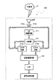
- FIG. 3 is a flowchart showing a control operation of the wireless sensor device 100, and the operation is periodically repeated by a timer function or the like built in the control circuit 5.
- step S1 the control circuit 5 controls the first switch 8 and the second switch 9 to select the first transmission line 6.
- control circuit 5 controls the signal processing circuit 4 and acquires an AD conversion signal from the signal processing circuit 4 in step S2.
- step S3 the amplitude information corresponding to the amplitude change of the detection signal caused by the motion of the detection target is extracted from the AD conversion signal acquired in step S2, and the detection sensitivity when the first transmission line 6 is selected is shown. It is held as 1 amplitude information A1.
- step S4 the control circuit 5 controls the first switch 8 and the second switch 9 to select the second transmission line 7.
- step S ⁇ b> 5 the control circuit 5 controls the signal processing circuit 4 and acquires an AD conversion signal from the signal processing circuit 4.
- step S6 the amplitude information corresponding to the amplitude change of the detection signal caused by the motion of the detection target is extracted from the AD conversion signal acquired in step S5, and the detection sensitivity when the second transmission line 7 is selected is shown. 2 amplitude information is stored as A2.
- step S7 the first amplitude information A1 held is compared with the threshold value for determining that the distance between the wireless sensor device 100 and the detection target is close to the null point and the sensitivity is lowered.
- 1 amplitude information A1 is larger than a threshold value, it transfers to procedure S8, and when 1st amplitude information A1 is below a threshold value, it transfers to procedure S10.
- step S8 the held first amplitude information A1 and second amplitude information A2 are compared, and if the first amplitude information A1 is large, the process proceeds to step S9. If the second amplitude information A2 is large, the second transmission line 7 is selected at this point, and the control process is terminated as it is. In this case, the first amplitude information A1 when the first transmission line 6 is selected is greater than or equal to the threshold, but the second amplitude information A2 when the second transmission line 7 is selected is larger than the first amplitude information A1. Therefore, the movement of the detection target can be detected with high sensitivity.
- step S9 the control circuit 5 controls the first switch 8 and the second switch 9, selects the first transmission line 6, and ends the control process.
- the first amplitude information A1 when the first transmission line 6 is selected is greater than or equal to the threshold value
- the second amplitude information A2 when the second transmission line 7 is selected is equal to or less than the first amplitude information A1. Therefore, it is possible to select the first transmission line and detect the movement of the detection target with high sensitivity.
- step S7 when the first amplitude information A1 is equal to or less than the threshold value and the process proceeds to step S10, the second amplitude information A2 held and the distance between the wireless sensor device 100 and the detection target approaches the null point in step S10.
- the second transmission line 7 is selected at this point in time when the second amplitude information A2 is larger than the threshold, and the control process is terminated as it is. To do. If the second amplitude information A2 is equal to or smaller than the threshold value, the process proceeds to step S11.
- step S11 since the output for detecting the detection target is not obtained regardless of which of the first transmission line 6 and the second transmission line 7 is selected, the control circuit 5 determines that there is no detection target. Then, a signal indicating that it is determined that there is no detection target is output, and the control process is terminated.
- the first transmission line 6 and the second transmission line 7 having different line lengths between the antenna 1 and the output terminal 2a, and the first The transmission line 6 and the second transmission line 7 are switched to have a first switch 8 and a second switch 9 for connecting the antenna 1 and the output terminal 2a.
- the first transmission line 6 and the second transmission line 7 The difference in length is less than one quarter of the wavelength of the transmission signal. For this reason, when the detection output decreases when the phase difference of the reflected wave with respect to the transmission output approaches the null point where the sensitivity decreases due to a change in the distance to the detection target, etc., transmission lines with different line lengths are selected. By switching between the two, the phase difference can be changed, and the minute variation can be detected with high sensitivity by avoiding the deterioration of the sensitivity for detecting the motion of the detection target.
- the transmission signal output to the output terminal 2a of the transmission circuit 2 and the reflection signal obtained by reflecting the transmission signal on the detection target are output terminals.
- the phase difference until it returns to 2a differs by ⁇ / 2 (rad) by switching the transmission line, and it is possible to reliably avoid a null point where the sensitivity is significantly lowered and to operate in a highly sensitive state. .
- the control circuit 5 performs control so as to switch a plurality of transmission lines, and selects and switches the transmission line that maximizes the signal output from the signal processing circuit 4, so that the movement of the detection target can be detected in a more sensitive state. can do.
- the wireless sensor device according to the embodiment of the present invention has been specifically described.
- the present invention is not limited to the above-described embodiment, and various modifications are made without departing from the scope of the invention. It is possible.
- the present invention can be modified as follows, and these embodiments also belong to the technical scope of the present invention.
- the transmission line has been described as an example including two transmission lines, the first transmission line and the second transmission line, but may be configured using three or more transmission lines. .
- the difference in the line length between the first transmission line and the second transmission line has been described by showing the case of ⁇ / 8.
- the transmission line is increased and the difference in the transmission line length is reduced. May be configured. In this case, it is possible to select a transmission line having a line length that is more accurate and sensitive.
- the signal processing circuit 4 amplifies a change in the amplitude of the detection signal and outputs an analog-to-digital conversion signal obtained by converting the amplified detection signal from an analog signal to a digital signal.
- it may be configured to perform signal processing such as band limitation and sampling.
Landscapes
- Engineering & Computer Science (AREA)
- Computer Networks & Wireless Communication (AREA)
- Radar, Positioning & Navigation (AREA)
- Remote Sensing (AREA)
- Physics & Mathematics (AREA)
- General Physics & Mathematics (AREA)
- Signal Processing (AREA)
- Radar Systems Or Details Thereof (AREA)
- Geophysics And Detection Of Objects (AREA)
Description
Vt2=Vo2+Vr2-2・Vo・Vr・cosθ
但しθは送信信号Voに対する反射波Vrの位相変移角度(位相差)
Vt=√(Vo2+Vr2-2・Vo・Vr・cosθ)
dVt/dθ=Vo・Vr・sinθ/√(Vo2+Vr2-2・Vo・Vr・cosθ)
減衰するので、送信出力Voに対して大幅に小さくVo>>Vrとなるので、(式3)は下記(式4)で近似することができる。
dVt/dθ≒Vr・sinθ
以下に第1実施形態における無線センサ装置について説明する。
L1=2(Lx+Le)=2Lx+2Le
L2=2(Lx+Le+λ/8)=2Lx+2Le+λ/4
ΔL=L2-L1=λ/4
2 送信回路
2a 出力端子
3 検波回路
4 信号処理回路
5 制御回路
6 第1伝送線路
7 第2伝送線路
8 第1スイッチ
9 第2スイッチ
100 無線センサ装置
Claims (3)
- 送信信号を放射し、前記送信信号が検出対象で反射した反射信号を受信するアンテナと、
前記アンテナに接続される出力端子を有し、前記送信信号を生成する送信回路と、
前記送信回路の前記出力端子に接続され、前記送信回路から前記送信信号を送信中に、前記送信信号の一部と前記アンテナで受信された前記反射信号と、が入力され検波される検波回路と、
前記検波回路に接続され、前記検波回路から出力される信号を処理する信号処理回路と、
前記送信回路に接続され、前記送信回路を制御する制御回路と、を有する無線センサ装置であって、
前記アンテナと前記出力端子との間に、線路長の異なる複数の伝送線路と、
前記複数の伝送線路を切換えて前記アンテナと前記出力端子を接続する切換え手段を有し、
前記複数の伝送線路の線路長の差が送信信号の波長の4分の1未満であることを特徴とする無線センサ装置。 - 前記複数の伝送線路が2つの伝送線路であり、前記2つの伝送線路の線路長が、前記送信信号の波長の8分の1異なることを特徴とする請求項1に記載の無線センサ装置。
- 前記制御回路は、前記複数の伝送線路を切換えるように制御し、前記信号処理回路から出力される信号が最大となる伝送線路を選択して切換えることを特徴とする請求項1または2に記載の無線センサ装置。
Priority Applications (3)
| Application Number | Priority Date | Filing Date | Title |
|---|---|---|---|
| EP13842032.8A EP2902801A4 (en) | 2012-09-27 | 2013-09-20 | WIRELESS SENSOR DEVICE |
| JP2014538162A JPWO2014050055A1 (ja) | 2012-09-27 | 2013-09-20 | 無線センサ装置 |
| US14/669,128 US20150208270A1 (en) | 2012-09-27 | 2015-03-26 | Wireless sensor device |
Applications Claiming Priority (2)
| Application Number | Priority Date | Filing Date | Title |
|---|---|---|---|
| JP2012-213344 | 2012-09-27 | ||
| JP2012213344 | 2012-09-27 |
Related Child Applications (1)
| Application Number | Title | Priority Date | Filing Date |
|---|---|---|---|
| US14/669,128 Continuation US20150208270A1 (en) | 2012-09-27 | 2015-03-26 | Wireless sensor device |
Publications (1)
| Publication Number | Publication Date |
|---|---|
| WO2014050055A1 true WO2014050055A1 (ja) | 2014-04-03 |
Family
ID=50387496
Family Applications (1)
| Application Number | Title | Priority Date | Filing Date |
|---|---|---|---|
| PCT/JP2013/005578 Ceased WO2014050055A1 (ja) | 2012-09-27 | 2013-09-20 | 無線センサ装置 |
Country Status (4)
| Country | Link |
|---|---|
| US (1) | US20150208270A1 (ja) |
| EP (1) | EP2902801A4 (ja) |
| JP (1) | JPWO2014050055A1 (ja) |
| WO (1) | WO2014050055A1 (ja) |
Cited By (2)
| Publication number | Priority date | Publication date | Assignee | Title |
|---|---|---|---|---|
| WO2015029794A1 (ja) * | 2013-09-02 | 2015-03-05 | アルプス電気株式会社 | 無線センサ装置 |
| JP2023086731A (ja) * | 2019-04-01 | 2023-06-22 | 立積電子股▲ふん▼有限公司 | モーション検出、ドップラーシフト検出、自己エンベロープ変調による位置決めのための方法、回路及び装置 |
Families Citing this family (1)
| Publication number | Priority date | Publication date | Assignee | Title |
|---|---|---|---|---|
| JP2017227487A (ja) * | 2016-06-21 | 2017-12-28 | ソニー株式会社 | 信号処理装置、信号処理方法及び信号受信装置 |
Citations (3)
| Publication number | Priority date | Publication date | Assignee | Title |
|---|---|---|---|---|
| JPH10239426A (ja) * | 1997-02-27 | 1998-09-11 | Ikuo Arai | 物標変位検出装置 |
| JP2007170990A (ja) * | 2005-12-22 | 2007-07-05 | Yokogawa Denshikiki Co Ltd | 微小移動検出装置 |
| WO2012042636A1 (ja) * | 2010-09-30 | 2012-04-05 | トヨタ自動車株式会社 | 移動物体検知装置 |
Family Cites Families (3)
| Publication number | Priority date | Publication date | Assignee | Title |
|---|---|---|---|---|
| US3562642A (en) * | 1968-12-02 | 1971-02-09 | Richard Hochschild | Apparatus and method for measuring properties of materials by sensing signals responsive to both amplitude and phase changes in transmitted or reflected microwave energy |
| US4063250A (en) * | 1975-12-16 | 1977-12-13 | Electrospace Systems, Inc. | Beam and null switch step steerable antenna system |
| JP2008267839A (ja) * | 2007-04-16 | 2008-11-06 | Matsushita Electric Ind Co Ltd | レーダシステム |
-
2013
- 2013-09-20 JP JP2014538162A patent/JPWO2014050055A1/ja active Pending
- 2013-09-20 WO PCT/JP2013/005578 patent/WO2014050055A1/ja not_active Ceased
- 2013-09-20 EP EP13842032.8A patent/EP2902801A4/en not_active Withdrawn
-
2015
- 2015-03-26 US US14/669,128 patent/US20150208270A1/en not_active Abandoned
Patent Citations (3)
| Publication number | Priority date | Publication date | Assignee | Title |
|---|---|---|---|---|
| JPH10239426A (ja) * | 1997-02-27 | 1998-09-11 | Ikuo Arai | 物標変位検出装置 |
| JP2007170990A (ja) * | 2005-12-22 | 2007-07-05 | Yokogawa Denshikiki Co Ltd | 微小移動検出装置 |
| WO2012042636A1 (ja) * | 2010-09-30 | 2012-04-05 | トヨタ自動車株式会社 | 移動物体検知装置 |
Non-Patent Citations (1)
| Title |
|---|
| See also references of EP2902801A4 * |
Cited By (4)
| Publication number | Priority date | Publication date | Assignee | Title |
|---|---|---|---|---|
| WO2015029794A1 (ja) * | 2013-09-02 | 2015-03-05 | アルプス電気株式会社 | 無線センサ装置 |
| JP2023086731A (ja) * | 2019-04-01 | 2023-06-22 | 立積電子股▲ふん▼有限公司 | モーション検出、ドップラーシフト検出、自己エンベロープ変調による位置決めのための方法、回路及び装置 |
| JP7615197B2 (ja) | 2019-04-01 | 2025-01-16 | 立積電子股▲ふん▼有限公司 | モーション検出、ドップラーシフト検出、自己エンベロープ変調による位置決めのための方法、回路及び装置 |
| US12216191B2 (en) | 2019-04-01 | 2025-02-04 | Richwave Technology Corp. | Methods, circuits, and apparatus for motion detection, doppler shift detection, and positioning by self-envelope modulation |
Also Published As
| Publication number | Publication date |
|---|---|
| EP2902801A4 (en) | 2016-06-01 |
| US20150208270A1 (en) | 2015-07-23 |
| EP2902801A1 (en) | 2015-08-05 |
| JPWO2014050055A1 (ja) | 2016-08-22 |
Similar Documents
| Publication | Publication Date | Title |
|---|---|---|
| US11709243B2 (en) | Occupancy detection apparatus using multiple antenna motion sensing | |
| EP2920988B1 (en) | Reconfigurable multiband antenna | |
| JP2011027695A5 (ja) | ||
| US10151825B2 (en) | Radar detection system | |
| JP2012098107A (ja) | レーダ装置 | |
| JPWO2012124352A1 (ja) | 車両傾斜検知装置 | |
| US20210075102A1 (en) | Antenna device and calibration method | |
| JPWO2014050055A1 (ja) | 無線センサ装置 | |
| CN107942136B (zh) | 电气测量系统及其工作方法 | |
| US7907084B2 (en) | Radar device and control method of radar device | |
| EP3128345B1 (en) | Position-detecting system | |
| JPWO2014057651A1 (ja) | 無線センサ装置 | |
| US20140118012A1 (en) | Sensor Device as Well as Method for Proximity and Touch Detection | |
| WO2011016578A1 (ja) | 近距離レーダ装置及び測距方法 | |
| JP6296483B2 (ja) | 周波数変調レーダ装置 | |
| CN114389601A (zh) | 相位追踪自我注入锁定雷达 | |
| JP2002168941A (ja) | レーダ装置およびそのビーム補正方法 | |
| JP6186882B2 (ja) | 物体変位検知装置、及び物体変位検知方法 | |
| JP2019158542A (ja) | レーダ装置 | |
| JP3486625B2 (ja) | レーダ装置 | |
| JP2008541025A (ja) | 目標物体との距離を確定するための方法および装置 | |
| JP6346663B2 (ja) | 無線センサ装置 | |
| JP6165870B2 (ja) | 無線センサ装置 | |
| JP2015040765A (ja) | レーダ装置 | |
| JP2007170990A (ja) | 微小移動検出装置 |
Legal Events
| Date | Code | Title | Description |
|---|---|---|---|
| 121 | Ep: the epo has been informed by wipo that ep was designated in this application |
Ref document number: 13842032 Country of ref document: EP Kind code of ref document: A1 |
|
| ENP | Entry into the national phase |
Ref document number: 2014538162 Country of ref document: JP Kind code of ref document: A |
|
| REEP | Request for entry into the european phase |
Ref document number: 2013842032 Country of ref document: EP |
|
| WWE | Wipo information: entry into national phase |
Ref document number: 2013842032 Country of ref document: EP |
|
| NENP | Non-entry into the national phase |
Ref country code: DE |