WO2014050351A1 - 無線通信システム、基地局装置、ユーザ端末及び無線通信方法 - Google Patents
無線通信システム、基地局装置、ユーザ端末及び無線通信方法 Download PDFInfo
- Publication number
- WO2014050351A1 WO2014050351A1 PCT/JP2013/072008 JP2013072008W WO2014050351A1 WO 2014050351 A1 WO2014050351 A1 WO 2014050351A1 JP 2013072008 W JP2013072008 W JP 2013072008W WO 2014050351 A1 WO2014050351 A1 WO 2014050351A1
- Authority
- WO
- WIPO (PCT)
- Prior art keywords
- power scaling
- transmission
- cell
- base station
- power
- Prior art date
- Legal status (The legal status is an assumption and is not a legal conclusion. Google has not performed a legal analysis and makes no representation as to the accuracy of the status listed.)
- Ceased
Links
Images


Classifications
-
- H—ELECTRICITY
- H04—ELECTRIC COMMUNICATION TECHNIQUE
- H04W—WIRELESS COMMUNICATION NETWORKS
- H04W72/00—Local resource management
- H04W72/20—Control channels or signalling for resource management
- H04W72/21—Control channels or signalling for resource management in the uplink direction of a wireless link, i.e. towards the network
-
- H—ELECTRICITY
- H04—ELECTRIC COMMUNICATION TECHNIQUE
- H04L—TRANSMISSION OF DIGITAL INFORMATION, e.g. TELEGRAPHIC COMMUNICATION
- H04L27/00—Modulated-carrier systems
- H04L27/26—Systems using multi-frequency codes
- H04L27/2601—Multicarrier modulation systems
-
- H—ELECTRICITY
- H04—ELECTRIC COMMUNICATION TECHNIQUE
- H04W—WIRELESS COMMUNICATION NETWORKS
- H04W52/00—Power management, e.g. Transmission Power Control [TPC] or power classes
- H04W52/04—Transmission power control [TPC]
- H04W52/06—TPC algorithms
- H04W52/14—Separate analysis of uplink or downlink
- H04W52/146—Uplink power control
-
- H—ELECTRICITY
- H04—ELECTRIC COMMUNICATION TECHNIQUE
- H04W—WIRELESS COMMUNICATION NETWORKS
- H04W52/00—Power management, e.g. Transmission Power Control [TPC] or power classes
- H04W52/04—Transmission power control [TPC]
- H04W52/30—Transmission power control [TPC] using constraints in the total amount of available transmission power
- H04W52/32—TPC of broadcast or control channels
- H04W52/325—Power control of control or pilot channels
-
- H—ELECTRICITY
- H04—ELECTRIC COMMUNICATION TECHNIQUE
- H04W—WIRELESS COMMUNICATION NETWORKS
- H04W52/00—Power management, e.g. Transmission Power Control [TPC] or power classes
- H04W52/04—Transmission power control [TPC]
- H04W52/30—Transmission power control [TPC] using constraints in the total amount of available transmission power
- H04W52/34—TPC management, i.e. sharing limited amount of power among users or channels or data types, e.g. cell loading
- H04W52/346—TPC management, i.e. sharing limited amount of power among users or channels or data types, e.g. cell loading distributing total power among users or channels
-
- H—ELECTRICITY
- H04—ELECTRIC COMMUNICATION TECHNIQUE
- H04W—WIRELESS COMMUNICATION NETWORKS
- H04W52/00—Power management, e.g. Transmission Power Control [TPC] or power classes
- H04W52/04—Transmission power control [TPC]
- H04W52/38—TPC being performed in particular situations
- H04W52/40—TPC being performed in particular situations during macro-diversity or soft handoff
-
- H—ELECTRICITY
- H04—ELECTRIC COMMUNICATION TECHNIQUE
- H04W—WIRELESS COMMUNICATION NETWORKS
- H04W56/00—Synchronisation arrangements
-
- H—ELECTRICITY
- H04—ELECTRIC COMMUNICATION TECHNIQUE
- H04W—WIRELESS COMMUNICATION NETWORKS
- H04W72/00—Local resource management
- H04W72/04—Wireless resource allocation
- H04W72/044—Wireless resource allocation based on the type of the allocated resource
- H04W72/0453—Resources in frequency domain, e.g. a carrier in FDMA
-
- H—ELECTRICITY
- H04—ELECTRIC COMMUNICATION TECHNIQUE
- H04W—WIRELESS COMMUNICATION NETWORKS
- H04W52/00—Power management, e.g. Transmission Power Control [TPC] or power classes
- H04W52/04—Transmission power control [TPC]
- H04W52/06—TPC algorithms
- H04W52/16—Deriving transmission power values from another channel
-
- H—ELECTRICITY
- H04—ELECTRIC COMMUNICATION TECHNIQUE
- H04W—WIRELESS COMMUNICATION NETWORKS
- H04W52/00—Power management, e.g. Transmission Power Control [TPC] or power classes
- H04W52/04—Transmission power control [TPC]
- H04W52/30—Transmission power control [TPC] using constraints in the total amount of available transmission power
- H04W52/34—TPC management, i.e. sharing limited amount of power among users or channels or data types, e.g. cell loading
- H04W52/343—TPC management, i.e. sharing limited amount of power among users or channels or data types, e.g. cell loading taking into account loading or congestion level
-
- H—ELECTRICITY
- H04—ELECTRIC COMMUNICATION TECHNIQUE
- H04W—WIRELESS COMMUNICATION NETWORKS
- H04W88/00—Devices specially adapted for wireless communication networks, e.g. terminals, base stations or access point devices
- H04W88/02—Terminal devices
-
- H—ELECTRICITY
- H04—ELECTRIC COMMUNICATION TECHNIQUE
- H04W—WIRELESS COMMUNICATION NETWORKS
- H04W88/00—Devices specially adapted for wireless communication networks, e.g. terminals, base stations or access point devices
- H04W88/08—Access point devices
Definitions
- the present invention relates to a radio communication system, a base station apparatus, a user terminal, and a radio communication method that perform multicarrier transmission at different transmission timings for a plurality of connected cells in the uplink.
- Release-8 LTE (hereinafter referred to as “Rel.8-LTE”) adopts a radio access scheme, and a downlink-based scheme based on orthogonal frequency division multiplex access (OFDMA) (OFDMA: Orthogonal Frequency Division Multiplexing Access).
- OFDMA orthogonal frequency division multiplex access
- SC-FDMA single-carrier frequency division multiple access
- LTE Long Term Evolution
- LTE-A LTE Advanced
- HetNet heterogeneous network
- LPN low power nodes
- CA Carrier Aggregation
- the carrier aggregation is a technology for treating a frequency band (1.4 MHz to 20 MHz) supported by LTE as one component carrier (CC: Component Carrier) and using a plurality of CCs simultaneously to widen the band.
- CC Component Carrier
- FIG. 1 illustrates a state in which a user terminal UE is connected to two cells of a base station apparatus eNB (macro cell) and a low power node LPN (low power cell) in HetNet.
- Component carriers CC # 1 and CC # 2 are assigned by carrier aggregation, and the user terminal UE is connected to the macro cell via the component carrier CC # 1 and is connected to the low power cell via the component carrier CC # 2.
- the small power node LPN2 has a small cell, the user terminal UE is located closer to the small power node LPN than the base station apparatus eNB. Rel., The latest standard of LTE-A.
- MTA Multiple Timing Advance
- TA Multiple Timing Advance
- the user terminal performed single transmission timing control (referred to as TA or Single TA)).
- the macro cell performs uplink transmission at transmission timing T1
- the low power cell performs uplink transmission at transmission timing T2 delayed by a predetermined time from transmission timing T1.
- LTE-A carrier aggregation using a maximum of 5 CC is realized.
- Rel Rel.
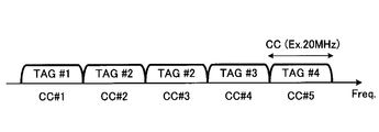
- MTA introduced in 11-LTE a maximum of five CCs are classified into a maximum of four TAGs (TA Groups), and transmission timing is controlled for each TAG.
- Fig. 2 illustrates a state in which 5 CCs are classified into 4 TAGs. Five CC # 1 to CC # 5 are classified into four TAG # 1 to TAG # 4. TAG # 1, CC # 2 for CC # 1, one TAG # 2 for CC # 2, CC # 3, TAG # 3 for CC # 4, TAG # 4 for CC # 5, respectively Assigned.
- the transmission timing difference between the TAGs is up to about 30 ⁇ s as shown in FIG. FIG. 3 shows a state in which the transmission timing is shifted by 30 ⁇ s, for example, between TAG # 1 and TAG # 2.
- the transmission power is controlled in units of CC and in units of subframes, and the total transmission power in each subframe is controlled so as not to exceed the upper limit.
- the present invention has been made in view of the above points, and provides a wireless communication system, a user terminal, a base station apparatus, and a wireless communication method that can apply power scaling in a PO section while maintaining uplink transmission quality. With the goal.
- a radio communication system is a radio communication system in which a plurality of cells are formed, a plurality of base station apparatuses that respectively form the cells included in the plurality of cells, at least a first cell included in the plurality of cells, and A user terminal connectable to a second cell, wherein the base station apparatus applies a control unit that controls uplink transmission timing for each timing group including one or a plurality of component carriers, and power scaling.
- the reception unit receives the ringed power scaling target information, the transmission unit transmits the uplink signal at different transmission timing for each timing group.
- a power control unit that applies power scaling to a timing group or a component carrier defined as the power scaling target information when the value exceeds the value.
- a base station apparatus is a base station apparatus that forms a cell in a wireless communication system in which a plurality of cells are formed, and sets an uplink transmission timing for each timing group including one or a plurality of component carriers.
- the user terminal is connected to a plurality of cells and is controlled at a transmission timing different for each timing group.
- a user terminal is a user terminal connected to a plurality of cells in a radio communication system in which a plurality of base station apparatuses form a plurality of cells, and receives the power scaling target information signaled from the base station apparatus , A transmission unit that transmits uplink signals at different transmission timings for each timing group, and a timing that is defined as the power scaling target information when the transmission power of the uplink signal that is a sum of connected cells exceeds a specified value And a power control unit that applies power scaling to the group or component carrier.
- the radio communication method is a radio communication method in a radio communication system in which a plurality of cells are formed, wherein the radio communication system includes a plurality of base station apparatuses that respectively form cells included in the plurality of cells, A user terminal connectable to at least the first cell and the second cell included in the plurality of cells, and controlling uplink transmission timing for each timing group including one or a plurality of component carriers, and power A timing group or component carrier to which scaling is applied is explicitly defined, and a timing group or component carrier defined as a power scaling target is signaled as power scaling target information from the base station apparatus to the user terminal; Yu In the terminal, a step of receiving power scaling target information signaled from the base station apparatus, a step of transmitting an uplink signal at a different transmission timing for each timing group, and an uplink in which the first cell and the second cell are summed Applying a power scaling to a timing group or a component carrier defined as the power scaling object information when the transmission power of the link signal exceeds a prescribed value.
- power scaling can be applied to a section in which uplink transmission power exceeds the upper limit value while maintaining uplink transmission quality.
- HetNet HetNet
- a component carrier TAG
- wireless communications system which concerns on embodiment.
- the essence of the present invention is that the base station apparatus eNB explicitly defines the TAG (or cell, CC, uplink physical channel) that preferentially applies power scaling to the user terminal UE, and preferentially applies power scaling.
- power scaling target information for specifying a TAG to be performed is signaled to the user terminal UE.
- TAG etc. which the user terminal UE should apply power scaling can be prescribed
- the base station apparatus eNB considers the communication environment (cell configuration, carrier aggregation status, transmission quality, traffic, transmission power, transport block size, etc.) and performs power scaling so that the degradation of the uplink transmission quality is suppressed.
- the applied TAG (or cell, CC, uplink physical channel) can be flexibly defined.
- the user terminal UE is connected to a macro cell (base station apparatus eNB) as a first cell, and is connected to a low power cell (low power node LPN) as a second cell.
- a macro cell base station apparatus eNB
- low power node LPN low power cell
- the first cell is a macro cell
- the second cell is a low power cell.
- the number of cells to which a user terminal can be connected simultaneously is not limited to two cells.
- the base station apparatus eNB and the low power node LPN are connected via a backhaul link, and the low power node LPN is controlled from the base station apparatus eNB.
- the small power node LPN receives information (for example, TAG information) necessary for communication with the user terminal UE from the base station apparatus eNB via the backhaul link.
- the base station apparatus eNB assigns a plurality of component carriers CC # 1 and CC # 2 to the user terminal UE by carrier aggregation, assigns one component carrier CC # 1 to the macro cell, and the other component carrier CC # 2. Is assigned to the low power cell, the cell configuration is instructed to the user terminal UE. Also, when the base station apparatus eNB assigns a plurality of component carriers to the user terminal UE and configures the cell to be connected to a plurality of cells simultaneously, the base station apparatus eNB classifies the plurality of component carriers assigned to the user terminal UE into TAGs, Control transmission timing for each TAG. In the example shown in FIG. 1, CC # 1 assigned to the macro cell is classified as TAG # 1, and CC # 2 assigned to the low power cell is classified as TAG # 2.
- the user terminal UE can transmit an uplink physical control channel and an uplink physical data channel via a plurality of component carriers CC # 1 and CC # 2. Specifically, the user terminal UE controls the transmission timing of the uplink subframe to the transmission timing T1 in the communication of the macro cell (TAG # 1, CC # 1), and the low power cell (TAG # 2, CC # 2). ), The transmission timing of the uplink subframe is controlled to the transmission timing T2. At this time, since the uplink transmission timing (T1, T2) is different between TAG # 1 and TAG # 2, a PO interval occurs (see FIG. 4).
- the base station apparatus eNB explicitly defines a TAG to which power scaling is applied in the user terminal UE.
- transmission quality can be a criterion for determining a TAG to which power scaling is applied.
- CC # 1 a communication environment is assumed in which, if the transmission quality of TAG # 1 (CC # 1) deteriorates, radio communication will be seriously hindered, but recovery is possible even if the transmission quality of TAG # 2 (CC # 2) deteriorates.
- the base station apparatus eNB can specify TAG # 2 (CC # 2) as a TAG to which power scaling is applied.
- traffic can be a criterion for determining the TAG to which power scaling is applied.
- TAG # 1 For example, it is assumed that the traffic of TAG # 1 (CC # 1) is very low and the traffic of TAG # 2 (CC # 2) is maintained at a high value.
- the base station apparatus eNB can specify TAG # 1 (CC # 1) as a TAG to which power scaling is applied. By using transmission quality and traffic as criteria, power scaling can be applied to the PO interval so as to suppress degradation of uplink transmission quality.
- the base station apparatus eNB may explicitly specify the TAG to which power scaling is applied in the user terminal UE, using the cell configuration as a criterion.
- Carrier aggregation is communication by a plurality of cells using a plurality of component carriers.
- a plurality of cells may be defined as two different types of cells, one cell may be defined as a primary cell (Pcell), and the other cell may be defined as a secondary cell (Scell).
- the base station apparatus eNB sets a primary cell and a secondary cell independently with respect to the user terminal UE to which carrier aggregation is applied.
- a primary cell is always composed of a set (combination) of one downlink component carrier and one uplink component carrier.
- the secondary cell is composed of at least one downlink component carrier, and may or may not be configured with an uplink component carrier.
- an uplink component carrier is also configured in the secondary cell.
- the uplink physical channel configuration in component carrier units is defined as follows.
- PRACH physical random access channel
- PUCCH physical uplink control channel
- PUSCH physical uplink shared channel
- SRS channel quality measurement reference signal
- the user terminal uses the PRACH parameters (frequency position, subframe position, Zadoff-Chu sequence number, etc.) and uplink component carrier information (center frequency, band) as necessary broadcast information from the downlink component carrier detected by cell search. Width, etc.), etc., and the PRACH is transmitted on the uplink component carrier corresponding to the downlink.
- the PUCCH is multiplexed at both ends of the band (intra-subframe frequency hopping is applied), and carries ACK / NACK that is a response signal to the downlink transmission signal, CQI (Channel Quality Indicator) report, and scheduling request.
- CQI is quality information indicating the quality of received data or channel quality.
- PUSCH is mapped with UL-SCH (uplink shared channel which is one of the transport channels).
- the base station apparatus eNB explicitly specifies a cell (primary cell or secondary cell) to which power scaling is applied as an example of setting the cell configuration as a criterion.
- a cell primary cell or secondary cell
- the first cell is operated for control signals and the second cell is used for data transmission, and the component carriers included in the first cell are classified into the first timing group and included in the second cell.
- the component carrier is classified into the second timing group, the physical uplink control channel (PUCCH) of the first timing group, the physical uplink shared channel (PUSCH) of the second timing group, or the reference signal (SRS) for channel quality measurement Is explicitly defined as the physical channel to which power scaling is applied.
- PUCCH physical uplink control channel
- PUSCH physical uplink shared channel
- SRS reference signal
- the transmission power of the control signal (PUCCH) in the primary cell (TAG # 1, CC # 1) decreases.
- the secondary cell (TAG # 2, CC # 2) for data transmission becomes a power scaling object, the transmission power of the data signal (PUSCH) in the secondary cell will decrease. Since the cell (primary cell or secondary cell) to which the power scaling is applied is notified to the user terminal UE, the control signal (PUCCH) or the data signal (PUSCH) can be power scaled by cell unit signaling in the HetNet environment.
- the base station apparatus eNB may explicitly specify a cell to which power scaling is applied by associating a physical channel with the cell as an example of setting the cell configuration as a determination criterion. Specifically, if the primary cell (TAG # 1, CC # 1) for the control signal is subject to power scaling, the data signal (PUSCH) in the primary cell is defined to be power scaled. If the secondary cell for transmission (TAG # 2, CC # 2) is subject to power scaling, the control signal (PUCCH) in the secondary cell may be regulated to be power scaled. Thereby, the power scaling of a physical channel unit is implement
- the base station apparatus eNB explicitly defines a physical channel to which power scaling is applied in units of physical channels. For example, in the primary cells (TAG # 1, CC # 1), the transmission quality of PRACH and PUCCH is prioritized over PUSCH, and in the secondary cells (TAG # 2, CC # 2), the transmission quality of PUSCH and SRS is higher than PUCCH. Assume priority. In this case, the base station apparatus eNB explicitly defines the PUSCH of TAG # 1 (CC # 1) as a target to which power scaling is applied, and the power scaling is applied to the PUCCH of TAG # 2 (CC # 2). Explicitly stipulate in the subject.
- the base station apparatus eNB notifies the user terminal UE of the TAG (or cell, CC, uplink physical channel) that is the target of power scaling defined by any one of the methods described above by higher layer signaling. Thereby, the overhead which increases by signaling TAG (or a cell, CC, an uplink physical channel) to which power scaling is applied can be suppressed to the minimum.
- the user terminal UE is notified of TAG (or cell, CC, uplink physical channel, packet) to which power scaling is applied from the base station apparatus eNB in the downlink.
- TAG or cell, CC, uplink physical channel, packet
- the user terminal UE applies power scaling to the TAG (or cell, CC, uplink physical channel) notified in advance and transmits Reduce power.
- the user terminal UE is notified of a TAG to which power scaling is applied in a state where it is connected to a plurality of cells.
- the transmission power of the CC included in the TAG notified in advance is reduced.
- the user terminal UE is notified of, for example, a primary cell (or a secondary cell) as a cell to which power scaling is applied while being connected to the primary cell and the secondary cell.
- a primary cell or a secondary cell
- the transmission power of the primary cell (or secondary cell) notified in advance is reduced.
- the user terminal UE acquires information in which a physical channel is associated with a cell in advance, and a cell to which power scaling is applied is notified from the base station apparatus eNB.
- the data signal (PUSCH) in the primary cell is regulated to be power-scaled if the primary cell (TAG # 1, CC # 1) for control signal is a power scaling target.
- the user terminal UE determines the PUSCH transmission power of the primary cell if the primary cell (TAG # 1, CC # 1) has been notified in advance as a power scaling target. Decrease.
- the control signal (PUCCH) in the secondary cell is regulated to be power scaled.
- the user terminal UE can reduce the transmission power of the PUCCH of the secondary cell if the secondary cell (TAG # 2, CC # 2) has been notified in advance as a power scaling target. Decrease.
- the base station apparatus eNB explicitly defines the PUSCH of TAG # 1 (CC # 1) as a target to which power scaling is applied, and the target to which power scaling is applied to the PUCCH of TAG # 2 (CC # 2).
- the user terminal UE is notified of the specified power scaling target information from the base station apparatus eNB.
- the user terminal UE reduces the transmission power of the physical channel notified in advance when the total transmission power exceeds the upper limit in the PO section. For example, if the PUSCH of TAG # 1 (CC # 1) is defined as a target to which power scaling is applied, the transmission power of the PUSCH of TAG # 1 (CC # 1) is reduced.
- the power scaling method A applies power scaling for each physical channel based on the priority for each uplink physical channel (PUSCH / PUCCH / PRACH / SRS).
- the priority is defined as PRACHA> PUCCH> PUSCH> SRS priority.
- the power scaling method B applies power scaling by giving priority to the primary cell over the secondary cell.
- Another aspect of the present invention provides a method of maintaining transmission quality without performing signaling by implicitly defining a TAG or the like to which power scaling is applied.
- specific power scaling methods (1) to (5) will be described.
- the user terminal UE may be defined such that power scaling is applied to a TAG with high transmission power. As a result, the probability that power scaling is applied to a TAG with low transmission power is reduced, and significant quality deterioration due to a significant decrease in power allocated to a TAG with low transmission power can be prevented.
- the user terminal UE is connected to a plurality of cells and MTA that realizes a plurality of transmission timings is applied to a plurality of connected cells in the uplink.
- the user terminal UE is notified of the TAG configuration (such as correspondence information between the component carrier number and the TAG number) regarding the component carrier assigned from the base station apparatus eNB.
- the several component carrier allocated to the uplink of the user terminal UE is classified into TAG # 1 and TAG # 2.
- TAG # 1 the transmission power of TAG # 1 is larger than the transmission power of TAG # 2 is shown.
- User terminal UE applies power scaling to TAG # 1 having higher transmission power when the total transmission power in the uplink exceeds the upper limit in the PO section. As a result, as shown in FIG. 5, the transmission power of TAG # 1 is reduced, and the total transmission power is suppressed below the upper limit. At this time, the transmission power of TAG # 2 to which power scaling is not applied is maintained.
- the user terminal UE may be defined to apply power scaling to a PUSCH having a small transport block size (number of transmission bits).
- a small transport block size number of transmission bits.
- data on an uplink transport channel (for example, UL-SCH) is organized into transport blocks of a certain size.
- TTI transmission time interval
- a transport block is transmitted between the user terminal UE and the base station apparatus eNB on the radio interface.
- the transport block is divided into code words and transmitted by the physical channel.
- one transport block having a variable size is transmitted for each TTI.
- a maximum of two size-variable transport blocks are transmitted for each TTI.
- the transport block size is defined in the transport format associated with the transport block. In the transport format, a modulation scheme and antenna mapping are defined in addition to the transport block size.
- the user terminal UE When the user terminal UE is connected to the first cell and the second cell and the total transmission power in the uplink exceeds the upper limit in the PO interval, the user terminal UE and the transport block assigned to the PUSCH of the first cell Power scaling is applied to the PUSCH having a small transport block size with respect to the transport block assigned to the PUSCH of the cell.
- the user terminal UE may be defined such that power scaling is applied to a TAG having a small total allocated bandwidth. Thereby, the consumed frequency bandwidth can be reduced.
- TAG # 1 Since one or more component carriers are classified in one TAG, there is a possibility that the total allocated bandwidth may be different among the TAGs. For example, only one component carrier CC # 1 is assigned to TAG # 1, and two component carriers CC # 2 and CC # 3 are assigned to TAG # 2.
- the user terminal UE is connected to a plurality of cells and MTA that realizes a plurality of transmission timings is applied to a plurality of connected cells in the uplink.
- the user terminal UE is notified of the TAG configuration (such as correspondence information between the component carrier number and the TAG number) regarding the component carrier assigned from the base station apparatus eNB.
- the user terminal UE applies power scaling to TAG # 1 having a small total bandwidth.
- the user terminal UE may be defined so that power scaling is applied to a new uplink packet. As a result, if the transmission power of the uplink retransmission packet is reduced, a reception error may occur again and the delay may accumulate. However, since the transmission power of the new packet is reduced, the delay time is minimized even if retransmission occurs. Can be reduced.
- uplink channels such as PUCCH and PUSCH are arranged in each uplink component carrier.
- the user terminal UE uses PUCCH and / or PUSCH to indicate channel state information (CSI: Channel Statement Information) indicating a downlink channel state and ACK / NACK (acknowledgment: Information indicating Positive Acknowledgement / Negative Acknowledgement) and uplink control information (UCI: Uplink Control Information) such as scheduling request (SR: SRScheduling Request) are transmitted to the base station apparatus eNB.
- CSI Channel Statement Information
- ACK / NACK acknowledgenowledgment: Information indicating Positive Acknowledgement / Negative Acknowledgement
- uplink control information UCI: Uplink Control Information
- SR SRScheduling Request
- each of the base station apparatus eNB and the user terminal UE has a hybrid ARQ entity, and each hybrid ARQ entity includes a hybrid ARQ process.
- the receiving side receives the transport block for the hybrid ARQ process, the receiving side tries to decode the block, and notifies the transmitting side through ACK / NACK of the result, that is, whether or not the block is correctly received.
- the subframe to be retransmitted is always known. In the case of FDD, retransmission is performed 8 subframes after data transmission is attempted. Whether or not to retransmit on the uplink is controlled by a new data indicator (NDI) included in the scheduling grant to the uplink sent by PDCCH. A new data index is set individually for each transport block transmitted. The user terminal UE can determine whether or not to transmit a new packet based on a new data indicator included in the PDCCH.
- NDI new data indicator
- the user terminal UE When the user terminal UE is connected to the first cell and the second cell and the total transmission power in the uplink exceeds the upper limit in the PO interval, the user terminal UE applies power scaling to the uplink new packet and Reduce transmission power.
- the user terminal UE may be defined such that power scaling is applied to the retransmission packet.
- power scaling is applied to retransmission packets with higher priority than new packets, so that the retransmission probability of new packets can be reduced.
- any one of the methods (1) to (5) may be combined with the power scaling methods A and B.
- the user terminal UE when applying power scaling to a TAG with large transmission power, applies power scaling for each uplink physical channel in the priority order of PRACH>PUCCH>PUSCH> SRS.
- power scaling when applying power scaling to TAG with large transmission power, user terminal UE applies power scaling which gives priority to Pcell over Scell.
- FIG. 6 is a network configuration diagram of a mobile communication system to which a radio communication method according to an embodiment of the present invention is applied.
- the radio communication system 1 includes base station apparatuses 20A and 20B and a plurality of first and second mobile station apparatuses 10A and 10B that communicate with the base station apparatuses 20A and 20B.
- Base station apparatuses 20 ⁇ / b> A and 20 ⁇ / b> B are connected to upper station apparatus 30, and upper station apparatus 30 is connected to core network 40.
- the base station devices 20A and 20B are connected to each other by wired connection or wireless connection.
- the first and second mobile station apparatuses 10A and 10B can communicate with the base station apparatuses 20A and 20B in the cells C1 and C2.
- the upper station device 30 includes, for example, an access gateway device, a radio network controller (RNC), a mobility management entity (MME), and the like, but is not limited thereto.
- RNC radio network controller
- MME mobility management entity
- the first and second mobile station apparatuses 10A and 10B include an LTE terminal and an LTE-A terminal.
- the mobile station apparatus 10 will be described unless otherwise specified.
- the mobile terminal apparatus is also a fixed terminal apparatus.
- the user equipment (UE) including
- OFDMA Orthogonal Frequency Division Multiple Access
- SC-FDMA Single Carrier-Frequency Division Multiple Access
- the wireless access method is not limited to this.
- OFDMA is a multi-carrier transmission scheme that performs communication by dividing a frequency band into a plurality of narrow frequency bands (subcarriers) and mapping data to each subcarrier.
- SC-FDMA is a single carrier transmission method that reduces interference between terminals by dividing a system band into bands each consisting of one or continuous resource blocks for each terminal, and a plurality of terminals using different bands. .
- a physical downlink shared channel (PDSCH) shared by each mobile station device 10 and a physical downlink control channel (PDCCH: Physical Downlink Control Channel) that is a downlink control channel, downlink L1 / L2 control channel).
- PDSCH physical downlink shared channel
- PDCCH Physical Downlink Control Channel
- User data that is, a normal data signal is transmitted through the physical downlink shared channel.
- precoding information for uplink MIMO transmission by the physical downlink control channel precoding information for uplink MIMO transmission by the physical downlink control channel, user ID for communication using the physical downlink shared channel, and information on the transport format of the user data (ie, Downlink Scheduling Information) ), User ID for communication using the physical uplink shared channel, transport format information of the user data (that is, Uplink Scheduling Grant), and the like are fed back.
- broadcast channels such as P-BCH (Physical-Broadcast Channel) and D-BCH (Dynamic Broadcast Channel) are transmitted.
- Information transmitted by P-BCH is MIB (Master Information Block)
- information transmitted by D-BCH is SIB (System Information Block).
- the D-BCH is mapped to the PDSCH and transmitted from the base station apparatus 20 to the mobile station apparatus 10.
- a physical uplink shared channel (PUSCH) shared by the mobile station devices 10 and a physical uplink control channel (PUCCH) that is an uplink control channel are used.
- User data that is, a normal data signal is transmitted through the physical uplink shared channel.
- precoding information for downlink MIMO transmission, acknowledgment information for downlink shared channel, downlink radio quality information (CQI), and the like are transmitted by the physical uplink control channel.
- a physical random access channel for initial connection and the like is defined.
- the mobile station apparatus 10 transmits a random access preamble to the base station apparatus 20 in the PRACH.
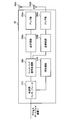
- the overall configuration of the base station apparatus according to the present embodiment will be described with reference to FIG. Note that the base station apparatuses 20A and 20B have basically the same configuration, and therefore will be described as the base station apparatus 20. Further, the first and second mobile station apparatuses 10A and 10B have the same configuration, and therefore will be described as the mobile station apparatus 10.
- the base station apparatus 20 includes a plurality of transmission / reception antennas 202a, 202b,... For amplification, transmission units 206a, 204b, transmission / reception units 206a, 206b, a baseband signal processing unit 208, and a call processing unit 210.
- the transmission path interface 212 is provided.
- the number of transmission / reception antennas 202a, 202b... Is eight, for example, and the amplifiers 204a, 204b... And the transmission / reception units 206a, 206b.
- User data transmitted from the base station apparatus 20 to the mobile station apparatus 10 by downlink is baseband signal processing from an upper station located above the base station apparatus 20, for example, the access gateway apparatus 30 via the transmission path interface 212. Input to the unit 208.
- the baseband signal processing unit 208 performs PDCP layer processing, user data division / combination, RLC layer transmission processing such as RLC (Radio Link Control) retransmission control transmission processing, MAC (Medium Access Control) retransmission control, for example, Hybrid ARQ (Hybrid Automatic Repeat reQuest) transmission processing, scheduling, transmission format selection, channel coding, inverse fast Fourier transform (IFFT) processing, and precoding processing are performed, and transmission / reception units 206a and 206b Transferred.
- the physical downlink control channel signal is also subjected to transmission processing such as channel coding and inverse fast Fourier transform, and transferred to the transmission / reception units 206a and 206b.
- the baseband signal processing unit 208 feeds back control information for communication in the cell to the mobile station apparatus 10 through the broadcast channel described above.
- the control information for communication in the cell includes, for example, a system bandwidth in uplink or downlink, resource block information allocated to the mobile station apparatus 10, and a route sequence for generating a random access preamble signal in the PRACH. Identification information (Root Sequence Index), etc. are included.
- frequency conversion processing for converting the baseband signal output by precoding from the baseband signal processing unit 208 to each antenna is converted into a radio frequency band, and then amplified by the amplifier units 204a and 204b. And transmitted from the transmitting and receiving antennas 202a and 202b.
- radio frequency signals received by the transmission / reception antennas 202a and 202b are amplified by the amplifier sections 204a and 204b, and transmitted and received by the transmission / reception sections 206a and 206b.
- the frequency is converted into a baseband signal and input to the baseband signal processing unit 208.
- the baseband signal processing unit 208 performs FFT processing, IDFT processing, error correction decoding, MAC retransmission control reception processing, RLC layer, and PDCP layer reception processing on user data included in the input baseband signal. And transferred to the access gateway apparatus 30 via the transmission path interface 212.
- the call processing unit 210 performs call processing such as communication channel setting and release, state management of the base station apparatus 20, and radio resource management.
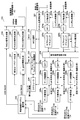
- FIG. 8 is a functional block diagram of baseband signal processing section 208 of base station apparatus 20 according to the present embodiment.
- the configuration of the scheduler 234 and the like is included.
- the reference signal (quality measurement reference signal) included in the received signal is input to the channel quality measurement unit 221.
- the channel quality measurement unit 221 measures uplink channel quality information (CQI) based on the reception state of the reference signal received from the mobile station apparatus 10.
- CQI uplink channel quality information
- the received signal input to the baseband signal processing unit 208 has a cyclic prefix added to the received signal removed by CP (Cyclic Prefix) removal units 222a and 222b, and then Fourier transformed by fast Fourier transform units 224a and 224b. It is converted to frequency domain information.
- Symbol synchronization sections 223a and 223b estimate the synchronization timing from the reference signal included in the received signal, and notify the estimation results to CP removal sections 222a and 222b.
- the received signal converted into the frequency domain information is demapped in the frequency domain by the subcarrier demapping units 225a and 225b.
- the subcarrier demapping units 225a and 225b perform demapping corresponding to the mapping in the mobile station apparatus 10.
- the frequency domain equalization unit 226 equalizes the received signal based on the channel estimation value given from the channel estimation unit 227.
- the channel estimation unit 227 estimates the channel state for each component carrier from the reference signal included in the reception signal, and the frequency domain equalization unit 226 equalizes the reception signal (codeword) for each component carrier.
- the inverse discrete Fourier transform units (IDFT) 228a, 228b, 228c perform inverse discrete Fourier transform on the received signal to return the frequency domain signal to the time domain signal.
- the data demodulation units 229a, 229b, and 229c and the data decoding units 230a, 230b, and 230c reproduce uplink user data based on the transmission format (coding rate, modulation scheme) for each component carrier. Thereby, transmission data of codeword # 1 corresponding to the first transport block, transmission data of codeword # 2 corresponding to the second transport block, codeword # 3 corresponding to the third transport block Is transmitted.
- the transmission data of the reproduced codewords # 1, # 2, and # 3 are output to the retransmission information channel selection unit 233.
- Retransmission information channel selection section 233 determines whether or not retransmission (ACK / NACK) is required for transmission data of codewords # 1, # 2, and # 3. Then, retransmission-related information such as NDI information and RV information is generated based on the necessity of retransmission in the transmission data of codewords # 1, # 2, and # 3. Also, retransmission information channel selection section 233 selects a channel (PHICH or PDCCH (UL grant)) for transmitting retransmission information.
- a channel PHICH or PDCCH (UL grant)
- the scheduler 234 Based on channel quality information (CQI) given from the channel quality measurement unit 221 and PMI information and RI information given from a precoding weight / rank number selection unit 235 described later, the scheduler 234 performs uplink / downlink resource allocation information. To decide.
- CQI channel quality information
- the precoding weight / rank number selection unit 235 determines the mobile station device from the uplink reception quality in the resource block allocated to the mobile station device 10. 10, a precoding weight (PMI) for controlling the phase and / or amplitude of the transmission signal is determined for each antenna. Further, precoding weight / rank number selection section 235 determines the number of ranks (RI) indicating the number of spatially multiplexed layers in the uplink, based on channel quality information (CQI) given from channel quality measurement section 221.
- the MCS selection unit 236 selects a modulation scheme / channel coding rate (MCS) based on the channel quality information (CQI) given from the channel quality measurement unit 221.
- MCS modulation scheme / channel coding rate
- the individual user data generation unit 237 receives individual downlink transmission data (individual user data) for each mobile station apparatus 10 from user data input from the upper station apparatus 30 such as an access gateway apparatus according to resource allocation information provided from the scheduler 234. Is generated.
- the individual user data generation unit 237 explicitly specifies a TAG for applying power scaling to the mobile station apparatus 10 based on a control signal input from the higher station apparatus or information provided from the scheduler 234. And functions as a control unit that signals power scaling target information such as TAG to which power scaling is applied to the mobile station apparatus 10.
- the target to which power scaling is applied is not limited to a TAG unit, but may be a component carrier, an uplink physical channel, or a packet unit.
- the transmission quality and / or traffic of the connected cell to which the mobile station device 10 is connected can be used as a criterion.
- the individual user data generation unit 237 may explicitly specify the TAG to which power scaling is applied in the mobile station apparatus 10 using the cell configuration as a criterion.
- the dedicated user data generation unit 237 may explicitly define an uplink physical channel to which power scaling is applied in units of physical channels. For example, in the primary cells (TAG # 1, CC # 1), the transmission quality of PRACH and PUCCH is prioritized over PUSCH, and in the secondary cells (TAG # 2, CC # 2), the transmission quality of PUSCH and SRS is higher than PUCCH. Prioritize.
- the base station apparatus 20 explicitly defines the PUSCH of TAG # 1 (CC # 1) as a target to which power scaling is applied, and the power scaling is applied to the PUCCH of TAG # 2 (CC # 2). Explicitly stipulate in the subject.
- the cell C1 as the first cell is operated for control signals
- the cell C2 as the second cell is operated for data transmission
- the component carriers included in the first cell C1 are classified into the first timing group
- the second cell When the component carriers included in C2 are classified into the second timing group, the PUCCH of the first timing group, the PUSCH and / or SRS of the second timing group are explicitly defined as physical channels to which power scaling is applied. .
- the dedicated user data generation unit 237 sends a tag (cell, CC, uplink physical channel, or packet) to which power scaling is explicitly defined by any one of the above-described methods to the mobile station apparatus 10 by higher layer signaling. Generate user data for notification.
- UL grant information generation section 238 includes ACK / NACK information and retransmission related information (NDI information and RV information) given from retransmission information channel selection section 233, resource allocation information given from scheduler 234, and precoding weight / rank number selection section. Based on the PMI and RI information provided from 233 and the MCS information provided from the MCS selection unit 236, a DCI format including the UL grant described above is generated.
- the PHICH signal generation unit 239 should retransmit the transport block to the mobile station apparatus 10 based on the ACK / NACK information and retransmission related information (NDI information and RV information) given from the retransmission information channel selection unit 233
- the PDSCH signal generation unit 240 generates downlink transmission data to be actually transmitted on the physical downlink shared channel (PDSCH) based on the downlink transmission data (individual user data) generated by the individual user data generation unit 237.
- the PDCCH signal generation unit 241 generates a PDCCH signal to be multiplexed on the physical downlink control channel based on the DCI format including the UL grant generated by the UL grant information generation unit 238.
- the PHICH signal, the PDSCH signal, and the PDCCH signal generated by the PHICH signal generation unit 239, the PDSCH signal generation unit 240, and the PDCCH signal generation unit 241 are input to the OFDM modulation unit 242.
- the OFDM modulation unit 242 performs OFDM modulation processing on the two series of signals including the PHICH signal, the PDSCH signal, and the PDCCH signal, and sends the signals to the transmission / reception units 206a and 206b.
- a TAG (or CC, uplink physical channel, packet) to which power scaling is applied is explicitly defined for the mobile station apparatus 10, and power scaling such as TAG to which power scaling is applied.
- Target information is signaled to the mobile station apparatus 10 in higher layer.
- the base station apparatus 20 considers the communication environment (cell configuration, carrier aggregation status, transmission quality, traffic, transmission power, transport block size, packet type, etc.) and applies a TAG (or cell, CC, uplink) to which power scaling is applied. Physical channels and packets) can be defined flexibly, and deterioration of uplink transmission quality due to application of power scaling can be suppressed.
- power scaling object information is notified to the mobile station apparatus 10 by higher layer signaling, overhead can be reduced.
- mobile station apparatus 10 includes two transmission / reception antennas 102a and 102b for MIMO transmission, amplifier sections 104a and 104b, transmission / reception sections 106a and 106b, and a baseband signal.
- a processing unit 108 and an application unit 110 are provided.
- radio frequency signals received by the two transmission / reception antennas 102a and 102b are amplified by the amplifier units 104a and 104b, frequency-converted by the transmission / reception units 106a and 106b, and converted into baseband signals.
- the baseband signal is subjected to FFT processing, error correction decoding, retransmission control reception processing, and the like by the baseband signal processing unit 108.
- downlink user data is transferred to the application unit 110.
- the application unit 110 performs processing related to layers higher than the physical layer and the MAC layer. Also, broadcast information in the downlink data is also transferred to the application unit 110.
- uplink user data is input from the application unit 110 to the baseband signal processing unit 108.
- the baseband signal processing unit 108 performs retransmission control (hybrid ARQ: Hybrid ARQ) transmission processing, channel coding, precoding, DFT processing, IFFT processing, and the like, and transfers them to the transmission / reception units 106a and 106b.
- hybrid ARQ Hybrid ARQ
- frequency conversion processing for converting the baseband signal output from the baseband signal processing unit 108 into a radio frequency band is performed, and then amplified by the amplifier units 104a and 104b and transmitted / received antennas 102a and 102b. Will be sent.
- FIG. 10 is a block diagram showing a configuration of the baseband signal processing unit 108.
- the baseband signal processing unit 108 includes a layer 1 processing unit 1081, a MAC processing unit 1082, an RLC processing unit 1083, a transmission power setting unit 1084, a TPC command reception processing unit 1085, and a TPC command format reception processing unit 1086. Consists mainly of.
- the layer 1 processing unit 1081 mainly performs processing related to the physical layer. For example, the layer 1 processing unit 1081 performs processing such as channel decoding, discrete Fourier transform, frequency demapping, inverse Fourier transform, and data demodulation on a signal received on the downlink. Further, the layer 1 processing unit 1081 performs processing such as channel coding, data modulation, frequency mapping, and inverse fast Fourier transform (IFFT) on a signal transmitted on the uplink.
- IFFT inverse fast Fourier transform
- the MAC processing unit 1082 performs retransmission control (hybrid ARQ) at the MAC layer for a signal received on the downlink, analysis of downlink scheduling information (specification of PDSCH transmission format, identification of PDSCH resource block), and the like. Further, the MAC processing unit 1082 performs processing such as MAC retransmission control for signals transmitted on the uplink, analysis of uplink scheduling information (specification of PUSCH transmission format, specification of PUSCH resource block), and the like.
- the RLC processing unit 1083 performs packet division, packet combination, retransmission control in the RLC layer, etc. on packets received on the downlink / packets transmitted on the uplink.
- the TPC command reception processing unit 1085 receives the TPC command notified from the base station apparatus 20, and determines the content of the TPC command.
- the TPC command reception processing unit 1085 determines the content of the TPC command based on the TPC command format received by the TPC command format reception processing unit 1086.
- the information of the TPC command is sent to the transmission power setting unit 1084.
- the TPC command format reception processing unit 1086 receives a signal of the TPC command format notified from the radio base station apparatus.
- the TPC command format reception processing unit 1086 receives a signal in a TPC command format with an extended number of bits (for example, 3 bits) during uplink MU-MIMO transmission. Further, the TPC command format reception processing unit 1086 receives a signal of a TPC command format defined in the LTE system when the uplink MU-MIMO transmission is not performed.
- the information of the TPC command format is sent to the transmission power setting unit 1084.
- the transmission power setting unit 1084 sets transmission power using transmission power control information (TPC command format and TPC command).
- the mobile station apparatus 10 is notified of TAG (or cell, CC, uplink physical channel, packet) to which power scaling is applied from the base station apparatus 20 in the downlink.
- the transmission power setting unit 1084 performs power scaling on a TAG (cell, CC, uplink physical channel, or packet) notified in advance when the total transmission power exceeds a specified upper limit value in a state where MTA is applied. To reduce transmit power.
- a TAG to which power scaling is applied is notified as a power scaling target in a state where the mobile station apparatus 10 is connected to the plurality of cells C1 and C2.
- the transmission power setting unit 1084 is included in the TAG notified in advance. Reduce the transmission power of the received CC.
- the mobile station apparatus 10 is notified of, for example, a primary cell as a cell to which power scaling is applied in a state where the mobile station apparatus 10 is connected to a cell C1 serving as a primary cell and a cell C2 serving as a secondary cell.
- the transmission power setting unit 1084 decreases the transmission power of the primary cell notified in advance.
- the mobile station apparatus 10 acquires information in which a physical channel is associated with a cell in advance, and a cell to which power scaling is applied is notified from the base station apparatus 20. For example, it is assumed that if the primary cell C1 (TAG # 1, CC # 1) for control signals is a power scaling target, the data signal (PUSCH) in the primary cell C1 is defined to be power scaled. When the total transmission power exceeds the upper limit regulation in the PO section, the mobile station device 10 is notified of the primary cell C1 (TAG # 1, CC # 1) as the target of power scaling in advance. Reduce transmission power.
- the control signal (PUCCH) in the secondary cell is regulated to be power scaled.
- the transmission power setting unit 1084 The transmission power of the cell's PUCCH is reduced.
- the base station apparatus 20 explicitly defines the PUSCH of TAG # 1 (CC # 1) as a target to which power scaling is applied, and the target of power scaling to be applied to the PUCCH of TAG # 2 (CC # 2).
- the mobile station apparatus 10 is notified of the specified power scaling information from the base station apparatus 20.
- the mobile station device 10 decreases the transmission power of the physical channel notified in advance. For example, if the PUSCH of TAG # 1 (CC # 1) is defined as a target to which power scaling is applied, the transmission power of the PUSCH of TAG # 1 (CC # 1) is reduced.
- the transmission power setting unit 1084 reduces the transmission power of the TAG (cell, CC, uplink physical channel, or packet) by applying one of the power scaling methods (1) to (5).
- the transmission power setting unit 1084 calculates the total transmission power for each TAG and applies power scaling to the TAG with the largest transmission power. To do. At this time, signaling of power scaling target information from the base station apparatus 20 is not necessary.
- the transmission power setting unit 1084 when it is defined that power scaling is applied to a PUSCH with a small transport block size (number of transmission bits), the transmission power setting unit 1084, for example, out of the transport blocks assigned to the cell C1 and the cell C2 The transmission power of a cell to which a large transport block is allocated is reduced. Thereby, the overhead at the time of retransmission can be reduced. At this time, signaling of power scaling target information from the base station apparatus 20 is not necessary.
- the transmission power setting unit 1084 allocates only CC # 1 to the cell C1 and CC # 2 and CC # to the cell C2. If 3 is assigned, power scaling is applied to the TAG of cell C1.
- the transmission power setting unit 1084 applies power scaling to the new packet corresponding to the determination result of the data new transmission / retransmission determination unit 115. To do.
- transmission power setting section 1084 applies power scaling to the retransmission packet in accordance with the determination result of new data transmission / retransmission determination section 115. Whether the target packet to which power scaling is applied is a new uplink packet or a retransmission packet depends on the operation of the system.
- the received signals output from the transmission / reception units 106 a and 106 b are demodulated by the OFDM demodulation unit 111.
- the PDSCH signal is input to the downlink PDSCH decoder 112
- the PHICH signal is input to the downlink PHICH decoder 113
- the PDCCH signal is input to the downlink PDCCH decoder 114. Is done.
- Downlink PDSCH decoding section 112 decodes the PDSCH signal and reproduces PDSCH transmission data.
- the downlink PHICH decoding unit 113 decodes the downlink PHICH signal.
- the downlink PDCCH decoding unit 114 decodes the PDCCH signal.
- the PDCCH signal includes a DCI format including UL grant.
- the PHICH signal decoded by downlink PHICH decoding unit 113 includes a hybrid ARQ confirmation response (ACK / NACK)
- data new transmission / retransmission determination unit 115 is based on the hybrid ARQ confirmation response (ACK / NACK). Then, new data transmission or retransmission is determined.
- the UL grant of the PDCCH signal includes a hybrid ARQ confirmation response (ACK / NACK)
- new data transmission or retransmission is determined based on the hybrid ARQ confirmation response (ACK / NACK).
- the new transmission data buffer unit 116 buffers uplink transmission data input from the application unit 110.
- the retransmission data buffer unit 117 buffers the transmission data output from the new transmission data buffer unit 116.
- the new data transmission / retransmission determination unit 115 notifies the determination result indicating that the data transmission is new, uplink transmission data is generated from the transmission data in the new transmission data buffer unit 116.
- uplink transmission data is generated from the transmission data in retransmission data buffer section 117.
- the generated uplink transmission data is input to a serial / parallel converter (not shown).
- uplink transmission data is serial-parallel converted into the number of codewords according to the number of uplink ranks.
- the code word indicates a coding unit of channel coding, and the number (code word number) is uniquely determined by the number of ranks and / or the number of transmission antennas.
- the number of code words is determined to be three is shown. Note that the number of codewords and the number of layers (number of ranks) are not necessarily equal.
- Uplink codeword # 1 transmission data, uplink codeword # 2 transmission data, and uplink codeword # 3 transmission data are input to data encoding sections 118a, 118b, and 118c.
- the uplink codeword # 1 transmission data is encoded.
- the uplink codeword # 1 transmission data encoded by the data encoding unit 118a is modulated by the data modulation unit 119a, multiplexed by the multiplexing unit 120a, and then subjected to discrete Fourier transform by the discrete Fourier transform unit (DFT) 121a.
- DFT discrete Fourier transform unit
- Time series information is converted into frequency domain information.
- the data encoding unit 118a and the data modulation unit 119a perform encoding and modulation processing of uplink codeword # 1 transmission data based on the MCS information from the downlink PDCCH decoding unit 114.
- Subcarrier mapping section 122a performs mapping in the frequency domain based on scheduling information (resource allocation information) from downlink PDCCH decoding section 114.
- scheduling information resource allocation information
- the same processing as that for the uplink codeword # 1 is performed on the uplink codewords # 2 and # 3.
- the uplink codeword # 1 transmission data after mapping is subjected to inverse fast Fourier transform on the transmission signal by inverse fast Fourier transform units (IFFT) 123a, 123b, and 123c to convert a frequency domain signal into a time domain signal.
- IFFT inverse fast Fourier transform units
- a cyclic prefix (CP) adding unit 124a, 124b, 124c adds a cyclic prefix to the transmission signal.
- the cyclic prefix functions as a guard interval for absorbing a multipath propagation delay and a difference in reception timing among a plurality of users in the base station apparatus 20.
- CC # 1 is assigned to cell C1
- two CC # 2 and CC # 3 are assigned to cell C2
- CC # 1 is classified as TAG # 1
- CC # 2 and CC # 3 are TAG.
- MTA is applied with respect to the mobile station apparatus 10 connected to the cell C1 and the cell C2
- TAG # 1 is set to the transmission timing T1
- TAG # 2 is set to the transmission timing T2.
- uplink data (codeword # 1) is transmitted on the uplink of cell C1
- uplink data (codeword # 2, # 3) is transmitted on the uplink of cell C2.
- the transmission timing of the transmission signal (codeword # 1) which is the uplink data of the cell C1 is controlled at the timing T1 by the MTA processing unit 125a.
- the transmission timing (codeword # 2) which is uplink data of the cell C2, is controlled by the MTA processing unit 125b at the timing T2, and the transmission signal (codeword # 3) is transmitted to the MTA processing unit 125c.
- the transmission timing is controlled to the timing T2.
- the transmission signal (codeword # 2) and transmission signal (codeword # 3), which are uplink data of the cell C2, are both controlled at the timing T2 and further combined by the combiner 126.
- the mobile station apparatus 10 since the mobile station apparatus 10 explicitly specifies and signals the TAG to which power scaling should be applied in the base station apparatus 20, the mobile station apparatus 10 responds to the notified power scaling object. Power scaling can be applied. As a result, the power scaling can be applied to the power scaling target determined by the base station apparatus 20 in consideration of the communication environment (cell configuration, carrier aggregation status, transmission quality, traffic, transmission power, transport block size, packet type, etc.). In addition, it is possible to suppress degradation of uplink transmission quality due to application of power scaling.
Landscapes
- Engineering & Computer Science (AREA)
- Computer Networks & Wireless Communication (AREA)
- Signal Processing (AREA)
- Mobile Radio Communication Systems (AREA)
Abstract
上りリンク伝送品質を保ちつつ、上限値を超える区間にパワースケーリングを適用可能にすること。複数セル(C1、C2)が形成される無線通信システム1において複数セルの1つである第1セルC1を形成する基地局装置(20)であって、1つ又は複数のコンポーネントキャリアが含まれるタイミンググループ毎に上りリンクの送信タイミングを制御する制御部(234)と、パワースケーリングが適用されるタイミンググループ又はコンポーネントキャリアが明示的に規定され、パワースケーリング対象として規定されたタイミンググループ又はコンポーネントキャリアをパワースケーリング対象情報としてユーザ端末(10)へシグナリングする送信部(106)と、を具備する。
Description
本発明は、上りリンクにおいて複数の接続セルに対して異なる送信タイミングでマルチキャリア送信する無線通信システム、基地局装置、ユーザ端末及び無線通信方法に関する。
UMTS(Universal Mobile Telecommunications System)における、更なる周波数利用効率及びピークデータレートの向上、遅延の低減などを目的として、LTE(Long Term Evolution)が検討されて来た(非特許文献1)。その結果、Release-8 LTE(以下、Rel.8-LTEという)では無線アクセス方式として、下りリンクについては直交周波数分割多重接続(OFDMA:Orthogonal Frequency Division Multiplexing Access)をベースとした方式が採用され、上りリンクについてはシングルキャリア周波数分割多重接続(SC-FDMA:Single-Carrier Frequency Division Multiple Access)をベースとした方式が採用された。Rel.8-LTEにおいては、1.4MHz~20MHzの可変帯域を用いて、下りリンクで最大300Mbps及び上りリンクで75Mbps程度の伝送レートを実現できる。現在、3GPPにおいて、UMTSネットワークの更なる広帯域化及び高速化を目的として、LTEの後継システム(LTEアドバンスト(LTE-A)という)が検討されている。
最近は、マクロセルのエリア内に送信電力の小さい小電力ノード(LPN)をオーバレイするヘテロジーニアスネットワーク(HetNet)を構築し、HetNetにキャリアアグリゲーション(CA: Carrier Aggregation)を適用することで、ネットワークの容量を大容量化することが検討されている。キャリアアグリゲーションは、LTEがサポートする周波数帯(1.4MHz~20MHz)を1つのコンポーネントキャリア(CC:Component Carrier)として扱い、複数CCを同時に利用することで広帯域化する技術である。HetNetにおいて、ユーザ端末が接続する接続セルをCC毎に変える事により、効率的なユーザ端末制御やトラフィックオフローディング等を実現できる。
図1に、HetNetにおいて、ユーザ端末UEが基地局装置eNB(マクロセル)と小電力ノードLPN(ローパワーセル)の2つのセルに接続した状態を例示する。ユーザ端末UEは、キャリアアグリゲーションによってコンポーネントキャリアCC#1及びCC#2が割り当てられており、コンポーネントキャリアCC#1を介してマクロセルと接続し、コンポーネントキャリアCC#2を介してローパワーセルと接続している。小電力ノードLPN2はセルが小さいので、ユーザ端末UEは基地局装置eNBよりも小電力ノードLPNに近い位置に存在する。LTE-Aの最新規格であるRel.11-LTEでは、それぞれのノード(基地局装置、小電力ノード)における受信タイミングを合わせる事を目的として、上りリンクにおいて複数のCCに対して複数の送信タイミングを実現するMTA(Multiple Timing Advance)機能が導入される(Rel. 10まではユーザ端末は単一の送信タイミング制御を行なっていた(TAまたはSingle TAと呼ばれる))。図1に示す例では、マクロセルは送信タイミングT1で上りリンク送信が行われ、ローパワーセルでは送信タイミングT1から所定時間遅延した送信タイミングT2で上りリンク送信が行われている。
LTE-Aにおいては最大5CCを用いたキャリアアグリゲーションが実現する。一方、Rel.11-LTEに導入されるMTAでは、最大5つのCCを最大4つのTAG(TA Group)に分類し、TAG毎に送信タイミングを制御する。
図2に5つのCCが4つのTAGに分類された状態を例示する。5つのCC#1~CC#5を4つのTAG#1~TAG#4に分類している。CC#1に対してTAG#1、2つのCC#2及びCC#3に対して1つのTAG#2、CC#4に対してTAG#3、CC#5に対してTAG#4、がそれぞれ割当てられている。
MTAが適用されたユーザ端末UEにおいてTAG毎に上りリンクの送信タイミングを制御する場合、図3に示すようにTAG間の送信タイミング差は最大で30μs程度まで生じる。図3にはTAG#1とTAG#2とで送信タイミングが例えば30μsずれた状態を示している。
3GPP, TR25.912 (V7.1.0), "Feasibility study for Evolved UTRA and UTRAN", Sept. 2006
3GPP, TS36.211 Sec. 8.1, "Timing Advance"
ところで、LTE-Aシステムにおける上りリンクでは、CC単位かつサブフレーム単位で送信電力が制御されており、各サブフレームでのトータル送信電力が上限規定を超えないように制御される。
一方、Rel.11-LTEで導入されるMTA機能がユーザ端末に適用された場合、TAG間でサブフレームが重複する部分(PO:Partial Overlap)が生じる可能性があるが、PO区間において送信電力の上限規定を超える可能性がある。例えば、図4に示すように、一方のTAGがハイパワーのサブフレーム区間では、他方のTAGがローパワーのサブフレーム区間となるようにTAG毎にサブフレーム単位で送信電力を制御したとしても、TAG間でハイパワーのサブフレームが重複するPO区間が生じると、PO区間では規定された送信電力の上限規定を超えてしまう。そこで、PO区間においてトータル送信電力が上限規定を超える可能性がある場合には、PO区間またはサブフレーム区間全体にパワースケーリングを適用してトータル送信電力を低減する必要がある。なお、本明細書においてパワースケーリングというときは、パワーを低減するだけでなく、パワーを0にする場合も含む。
しかしながら、PO区間にパワースケーリングを適用すると、信号電力が低減するため、上りリンク伝送品質が劣化する課題が生じる。
本発明は、かかる点に鑑みてなされたものであり、上りリンク伝送品質を保ちつつ、PO区間におけるパワースケーリングを適用可能な無線通信システム、ユーザ端末、基地局装置及び無線通信方法を提供することを目的とする。
本発明に係る無線通信システムは、複数セルが形成される無線通信システムにおいて、前記複数セルに含まれる各セルをそれぞれ形成する複数の基地局装置と、前記複数セルに含まれる少なくとも第1セル及び第2セルに接続可能なユーザ端末と、を備え、前記基地局装置は、1つ又は複数のコンポーネントキャリアが含まれるタイミンググループ毎に上りリンクの送信タイミングを制御する制御部と、パワースケーリングが適用されるタイミンググループ又はコンポーネントキャリアが明示的に規定され、パワースケーリング対象として規定されたタイミンググループ又はコンポーネントキャリアをパワースケーリング対象情報として前記ユーザ端末へシグナリングする送信部と、を具備し、前記ユーザ端末は、前記基地局装置からシグナリングされたパワースケーリング対象情報を受信する受信部と、タイミンググループ毎に異なる送信タイミングで上りリンク信号を送信する送信部と、第1セル及び第2セルを合計した上りリンク信号の送信電力が規定値を超える場合に、前記パワースケーリング対象情報として規定されたタイミンググループ又はコンポーネントキャリアに対してパワースケーリングを適用する電力制御部と、を具備したことを特徴とする。
本発明に係る基地局装置は、複数セルが形成される無線通信システムにおいてセルを形成する基地局装置であって、1つ又は複数のコンポーネントキャリアが含まれるタイミンググループ毎に上りリンクの送信タイミングを制御する制御部と、パワースケーリングが適用されるタイミンググループ又はコンポーネントキャリアが明示的に規定され、パワースケーリング対象として規定されたタイミンググループ又はコンポーネントキャリアをパワースケーリング対象情報としてユーザ端末へシグナリングする送信部と、を具備し、前記ユーザ端末は、複数セルに接続してタイミンググループ毎に異なる送信タイミングに制御される、ことを特徴とする。
本発明に係るユーザ端末は、複数の基地局装置が複数セルを形成する無線通信システムにおいて複数セルに接続するユーザ端末であって、前記基地局装置からシグナリングされたパワースケーリング対象情報を受信する受信部と、タイミンググループ毎に異なる送信タイミングで上りリンク信号を送信する送信部と、接続セルを合計した上りリンク信号の送信電力が規定値を超える場合に、前記パワースケーリング対象情報として規定されたタイミンググループ又はコンポーネントキャリアに対してパワースケーリングを適用する電力制御部と、を具備したことを特徴とする。
本発明に係る無線通信方法は、複数セルが形成される無線通信システムにおける無線通信方法において、前記無線通信システムは、前記複数セルに含まれる各セルをそれぞれ形成する複数の基地局装置と、前記複数セルに含まれる少なくとも第1セル及び第2セルに接続可能なユーザ端末と、を備え、1つ又は複数のコンポーネントキャリアが含まれるタイミンググループ毎に上りリンクの送信タイミングを制御するステップと、パワースケーリングが適用されるタイミンググループ又はコンポーネントキャリアが明示的に規定され、パワースケーリング対象として規定されたタイミンググループ又はコンポーネントキャリアをパワースケーリング対象情報として前記基地局装置から前記ユーザ端末へシグナリングするステップと、前記ユーザ端末において、前記基地局装置からシグナリングされたパワースケーリング対象情報を受信するステップと、タイミンググループ毎に異なる送信タイミングで上りリンク信号を送信するステップと、第1セル及び第2セルを合計した上りリンク信号の送信電力が規定値を超える場合に、前記パワースケーリング対象情報として規定されたタイミンググループ又はコンポーネントキャリアに対してパワースケーリングを適用するステップと、を具備したことを特徴とする。
本発明によれば、上りリンク伝送品質を保ちつつ、上りリンクの送信電力が上限値を超える区間にパワースケーリングを適用可能である。
本発明の骨子は、基地局装置eNBがユーザ端末UEに対してパワースケーリングを優先的に適用するTAG(又はセル、CC、上り物理チャネル)を明示的に規定し、パワースケーリングを優先的に適用するTAG等を特定するためのパワースケーリング対象情報をユーザ端末UEにシグナリングすることにある。これにより、ユーザ端末UEがパワースケーリングを適用すべきTAG等を、基地局装置eNBにおいて規定できるので、ネットワーク運用の自由度を上げることができる。基地局装置eNBは通信環境(セル構成、キャリアアグリゲーション状況、伝送品質、トラフィック、送信電力、トランスポートブロックサイズ等)を考慮して、上りリンク伝送品質の劣化が抑制されるように、パワースケーリングを適用するTAG(又はセル、CC、上り物理チャネル)を柔軟に規定できる。
図1に示すネットワーク構成を参照して具体的に説明する。
ユーザ端末UEは、第1セルとしてのマクロセル(基地局装置eNB)に接続すると共に、第2セルとしてのローパワーセル(小電力ノードLPN)に接続している。なお、本発明において、第1セルがマクロセルで第2セルがローパワーセルであることは必須要件ではない。また、本発明はユーザ端末が同時接続可能なセル数は2セルに限定されない。基地局装置eNBと小電力ノードLPNとはバックホールリンクを介して接続されており、基地局装置eNBから小電力ノードLPNを制御している。小電力ノードLPNは、基地局装置eNBからバックホールリンクを介してユーザ端末UEとの通信に必要な情報(例えば、TAG情報)を受け取る。
ユーザ端末UEは、第1セルとしてのマクロセル(基地局装置eNB)に接続すると共に、第2セルとしてのローパワーセル(小電力ノードLPN)に接続している。なお、本発明において、第1セルがマクロセルで第2セルがローパワーセルであることは必須要件ではない。また、本発明はユーザ端末が同時接続可能なセル数は2セルに限定されない。基地局装置eNBと小電力ノードLPNとはバックホールリンクを介して接続されており、基地局装置eNBから小電力ノードLPNを制御している。小電力ノードLPNは、基地局装置eNBからバックホールリンクを介してユーザ端末UEとの通信に必要な情報(例えば、TAG情報)を受け取る。
基地局装置eNBは、キャリアアグリゲーションによってユーザ端末UEに対して複数のコンポーネントキャリアCC#1、CC#2を割当てると共に、一方のコンポーネントキャリアCC#1をマクロセルに割当て、もう一方のコンポーネントキャリアCC#2をローパワーセルに割り当てるように、セル構成をユーザ端末UEに指示する。また、基地局装置eNBは、ユーザ端末UEに複数のコンポーネントキャリアを割り当て、複数のセルに同時接続するようにセル構成した場合は、ユーザ端末UEに割り当てた複数のコンポーネントキャリアをTAGに分類し、TAG毎の送信タイミングの制御を行う。図1に示される例では、マクロセルに割り当てられたCC#1はTAG#1に分類され、ローパワーセルに割り当てられたCC#2はTAG#2に分類されている。
ユーザ端末UEは、複数のコンポーネントキャリアCC#1、CC#2を介して、上り物理制御チャネル、上り物理データチャネルを送信することができる。具体的には、ユーザ端末UEは、マクロセル(TAG#1、CC#1)の通信では上りリンクのサブフレームの送信タイミングを送信タイミングT1に制御し、ローパワーセル(TAG#2、CC#2)の通信では上りリンクのサブフレームの送信タイミングを送信タイミングT2に制御する。このとき、TAG#1とTAG#2とで上りリンクの送信タイミング(T1、T2)が異なるので、PO区間が生じる(図4参照)。
基地局装置eNBは、ユーザ端末UEにおいてパワースケーリングが適用されるTAGを明示的に規定する。例えば、パワースケーリングが適用されるTAGを決定するために伝送品質を判断規範にすることができる。例えば、TAG#1(CC#1)の伝送品質が劣化すると無線通信に大きな支障を生じるが、TAG#2(CC#2)の伝送品質が劣化しても回復可能である通信環境を想定する。この場合、基地局装置eNBは、TAG#2(CC#2)をパワースケーリングが適用されるTAGに規定することができる。又は、パワースケーリングが適用されるTAGを決定するためにトラフィックを判断規範にすることができる。例えば、TAG#1(CC#1)のトラフィックが非常に低く、TAG#2(CC#2)のトラフィックを高い値に維持する場合を想定する。この場合、基地局装置eNBは、TAG#1(CC#1)をパワースケーリングが適用されるTAGに規定することができる。伝送品質、トラフィックを判断規範にすることにより、上りリンク伝送品質の劣化を抑制するように、PO区間にパワースケーリングを適用できる。
また、基地局装置eNBは、セル構成を判断規範にして、ユーザ端末UEにおいてパワースケーリングが適用されるTAGを明示的に規定しても良い。キャリアアグリゲーションは、複数のコンポーネントキャリアを用いた複数セルによる通信である。複数セル(コンポーネントキャリア)が異なる2種類のセルとして定義され、1つのセルがプライマリセル(Pcell)と定義され、その他のセルがセカンダリセル(Scell)と定義されても良い。基地局装置eNBは、キャリアアグリゲーションを適用するユーザ端末UEに対してプライマリセルとセカンダリセルの設定を独立に行う。プライマリセルは、必ず1つの下りリンクコンポーネントキャリアと1つの上りリンクコンポーネントキャリアのセット(組み合わせ)から構成される。セカンダリセルは、少なくとも1つの下りリンクコンポーネントキャリアから構成され、上りリンクコンポーネントキャリアが構成される場合と構成されない場合がある。ここでは、セカンダリセルにおいても上りリンクコンポーネントキャリアが構成される。
今、図1に示すHetNetにおいて、プライマリセル(TAG#1、CC#1)を制御信号用とし、セカンダリセル(TAG#2、CC#2)をデータ伝送用として運用する場合を想定する。Rel.10-LTEでは、コンポーネントキャリア単位での上りリンク物理チャネル構成は次のように規定されている。上りリンク物理チャネルとして、物理ランダムアクセスチャネル(PRACH)、物理上り制御チャネル(PUCCH)、物理上り共有チャネル(PUSCH)、チャネル品質測定用の参照信号(SRS: Sounding Reference Signal)が規定されている。PRACHは、ユーザ端末からネットワークへの初期アクセス時に使用される。ユーザ端末は、セルサーチで検出した下りのコンポーネントキャリアから必要な報知情報として、PRACHのパラメータ(周波数位置,サブフレーム位置,Zadoff-Chu系列番号等)、上りのコンポーネントキャリアの情報(中心周波数,帯域幅等)等を受信し、下りに対応する上りのコンポーネントキャリアでPRACHを送信する。PUCCHは、帯域の両端に多重(サブフレーム内周波数ホッピングを適用)され、下りリンクの送信信号に対する応答信号(response)であるACK/NACK、CQI(Channel Quality Indicator)レポート、スケジューリングリクエストを運ぶ。CQIとは受信したデータの品質、もしくは通信路品質を示す品質情報である。PUSCHは、UL-SCH(トランスポートチャネルの1つである上り共有チャネル)がマッピングされる。
基地局装置eNBは、セル構成を判断規範にする一例として、パワースケーリングを適用するセル(プライマリセルまたはセカンダリセル)を明示的に規定する。例えば、基地局装置eNBは、第1セルが制御信号用、第2セルがデータ伝送用として運用され、第1セルに含まれるコンポーネントキャリアが第1タイミンググループに分類され、第2セルに含まれるコンポーネントキャリアが第2タイミンググループに分類される場合、第1タイミンググループの物理上り制御チャネル(PUCCH)、第2タイミンググループの物理上り共有チャネル(PUSCH)及び又はチャネル品質測定用の参照信号(SRS)が、パワースケーリングが適用される物理チャネルとして明示的に規定される。
制御信号用のプライマリセル(TAG#1、CC#1)がパワースケーリング対象となれば、プライマリセル(TAG#1、CC#1)における制御信号(PUCCH)の送信電力が減少する。また、データ伝送用のセカンダリセル(TAG#2、CC#2)がパワースケーリング対象となれば、セカンダリセルにおけるデータ信号(PUSCH)の送信電力が減少する。パワースケーリングを適用するセル(プライマリセルまたはセカンダリセル)をユーザ端末UEに通知するので、HetNet環境下においてセル単位のシグナリングで、制御信号(PUCCH)又はデータ信号(PUSCH)をパワースケーリングできる。
また、基地局装置eNBは、セル構成を判断規範にする一例として、セルに物理チャネルを紐づけて、パワースケーリングを適用するセルを明示的に規定しても良い。具体的には、制御信号用のプライマリセル(TAG#1、CC#1)がパワースケーリング対象となれば、プライマリセルにおけるデータ信号(PUSCH)がパワースケーリングされるように規定され、同様に、データ伝送用のセカンダリセル(TAG#2、CC#2)がパワースケーリング対象となれば、セカンダリセルにおける制御信号(PUCCH)がパワースケーリングされるように規定されても良い。これにより、パワースケーリングを適用するセル(プライマリセルまたはセカンダリセル)をユーザ端末UEに通知することで、物理チャンネル単位のパワースケーリングが実現される。
基地局装置eNBは、パワースケーリングを適用する物理チャネルを物理チャネル単位で明示的に規定する。例えば、プライマリセル(TAG#1、CC#1)ではPRACH及びPUCCHの伝送品質をPUSCHよりも優先し、またセカンダリセル(TAG#2、CC#2)ではPUSCH及びSRSの伝送品質をPUCCHよりも優先することを想定する。この場合、基地局装置eNBは、TAG#1(CC#1)のPUSCHをパワースケーリングが適用される対象に明示的に規定し、TAG#2(CC#2)のPUCCHをパワースケーリングが適用される対象に明示的に規定する。
基地局装置eNBは、上述したいずれかの方法で規定した、パワースケーリング対象となるTAG(又はセル、CC、上り物理チャネル)を、上位レイヤシグナリングによってユーザ端末UEへ通知する。これにより、パワースケーリングを適用するTAG(又はセル、CC、上り物理チャネル)をシグナリングすることにより増加するオーバーヘッドを最小限に抑制できる。
ユーザ端末UEは、パワースケーリングを適用するTAG(又はセル、CC、上り物理チャネル、パケット)が、基地局装置eNBから下りリンクで通知される。ユーザ端末UEは、MTAが適用された状態で、トータル送信電力が上限規定を超える場合には、予め通知されたTAG(又はセル、CC、上り物理チャネル)に対してパワースケーリングを適用して送信電力を減少させる。
ユーザ端末UEは、複数セルに接続されている状態において、パワースケーリングを適用するTAGが通知されていると仮定する。この場合、ユーザ端末UEに対してMTAが適用されていて、PO区間においてトータル送信電力が上限規定を超える場合に、予め通知されたTAGに含まれたCCの送信電力を減少させる。
また、ユーザ端末UEは、プライマリセルとセカンダリセルに接続されている状態において、パワースケーリングを適用するセルとして例えばプライマリセル(またはセカンダリセル)が通知されていると仮定する。この場合、ユーザ端末UEに対してMTAが適用されていて、PO区間においてトータル送信電力が上限規定を超える場合に、予め通知されたプライマリセル(又はセカンダリセル)の送信電力を減少させる。
また、ユーザ端末UEは、予めセルに物理チャネルが紐づけられた情報を取得していて、パワースケーリングを適用するセルが基地局装置eNBから通知される。例えば、制御信号用のプライマリセル(TAG#1、CC#1)がパワースケーリング対象となれば、プライマリセルにおけるデータ信号(PUSCH)がパワースケーリングされるように規定されているとする。ユーザ端末UEは、PO区間においてトータル送信電力が上限規定を超える場合、予めプライマリセル(TAG#1、CC#1)がパワースケーリングの対象として通知されていれば、プライマリセルのPUSCHの送信電力を減少させる。又は、データ伝送用のセカンダリセル(TAG#2、CC#2)がパワースケーリング対象となれば、セカンダリセルにおける制御信号(PUCCH)がパワースケーリングされるように規定されているとする。ユーザ端末UEは、PO区間においてトータル送信電力が上限規定を超える場合、予めセカンダリセル(TAG#2、CC#2)がパワースケーリングの対象として通知されていれば、セカンダリセルのPUCCHの送信電力を減少させる。
また、基地局装置eNBがTAG#1(CC#1)のPUSCHをパワースケーリングが適用される対象に明示的に規定し、TAG#2(CC#2)のPUCCHをパワースケーリングが適用される対象に明示的に規定している場合、ユーザ端末UEは、この規定されたパワースケーリング対象情報が基地局装置eNBから通知される。この場合、ユーザ端末UEは、PO区間においてトータル送信電力が上限規定を超える場合に、予め通知された物理チャネルの送信電力を減少させる。例えば、TAG#1(CC#1)のPUSCHをパワースケーリングが適用される対象に規定されていれば、TAG#1(CC#1)のPUSCHの送信電力を減少させる。
また、上記したパワースケーリングの適用方法と以下に示すいずれかの方法A,Bとを組み合わせても良い。
パワースケーリング方法Aは、上りリンク物理チャネル(PUSCH/PUCCH/PRACH/SRS)毎の優先度に基づいて、物理チャネル毎にパワースケーリングを適用する。例えば、PRACH > PUCCH > PUSCH > SRSの優先度に規定する。
パワースケーリング方法Bは、プライマリセルをセカンダリセルよりも優先してパワースケーリングを適用する。
本発明の別の側面は、パワースケーリングを適用するTAG等を暗示的に規定することにより、シグナリングを行わずに、伝送品質を保つ方法を提供する。以下に、具体的なパワースケーリング方法(1)から(5)を説明する。
(1)ユーザ端末UEは、送信電力の大きいTAGにパワースケーリングが適用されるように規定されても良い。これにより、送信電力の小さいTAGにパワースケーリングが適用される確率が下がり、送信電力の小さいTAGに割り当てる電力が著しく減少することによる大幅な品質劣化を防止できる。
ユーザ端末UEは、複数セルに接続されている状態において、上りリンクにおいて複数の接続セルに対して複数の送信タイミングを実現するMTAが適用されている場合を想定する。ユーザ端末UEは、基地局装置eNBから割り当てられているコンポーネントキャリアに関するTAG構成(コンポーネントキャリア番号とTAG番号との対応情報等)が通知される。
今、図5に示すように、ユーザ端末UEの上りリンクに割り当てられた複数のコンポーネントキャリアが、TAG#1とTAG#2に分類されている。パワースケーリング適用前の段階において、TAG#1の送信電力がTAG#2の送信電力よりも大きい状態が示されている。
ユーザ端末UEは、PO区間において上りリンクでのトータル送信電力が上限規定を超える場合、送信電力のより大きいTAG#1に対してパワースケーリングを適用する。その結果、図5に示すようにTAG#1の送信電力が減少してトータル送信電力が上限規定以下に抑えられる。このとき、パワースケーリングが適用されないTAG#2の送信電力は維持される。
(2)ユーザ端末UEは、トランスポートブロックサイズ(伝送ビット数)の小さいPUSCHにパワースケーリングを適用するように規定されても良い。これにより、小サイズのトランスポートブロックがパワースケーリングにより品質劣化を防止でき、サイズの大きいトランスポートブロックの品質を劣化させるのに比べて、再送時のオーバーヘッドを低減できる。
LTEでは、上りリンクトランスポートチャネル(例えばUL-SCH)上のデータは、あるサイズのトランスポートブロックに編成される。各サブフレーム(送信時間間隔:TTI)において、トランスポートブロックがユーザ端末UEと基地局装置eNBとの間を無線インタフェース上で送信される。トランスポートブロックはコードワードに分割されて物理チャネルにより伝送される。1アンテナ送信の場合、大きさが可変の1つのトランスポートブロックがTTI毎に送信される。複数アンテナ送信の場合、最大で2つの大きさ可変のトランスポートブロックがTTI毎に送信される。トランスポートブロックサイズは、トランスポートブロックに付随したトランスポートフォーマットに規定される。トランスポートフォーマットは、トランスポートブロックサイズの他に、変調方式及びアンテナマッピングが規定される。
ユーザ端末UEは、第1セルと第2セルに接続されていて、PO区間において上りリンクでのトータル送信電力が上限規定を超える場合、第1セルのPUSCHに割り当てられたトランスポートブロックと第2セルのPUSCHに割り当てられたトランスポートブロックとの間で、トランスポートブロックサイズの小さいPUSCHにパワースケーリングを適用する。
(3)ユーザ端末UEは、合計割当て帯域幅の小さいTAGにパワースケーリングが適用されるように規定されても良い。これにより、消費する周波数帯域幅を低減できる。
1つのTAGには1つまたは複数のコンポーネントキャリアが分類されるので、TAG間で合計割当て帯域幅が異なる可能性がある。例えば、TAG#1は1つのコンポーネントキャリアCC#1だけが割り当てられ、TAG#2は2つのコンポーネントキャリアCC#2、CC#3が割り当てられる。
ユーザ端末UEは、複数セルに接続されている状態において、上りリンクにおいて複数の接続セルに対して複数の送信タイミングを実現するMTAが適用されている場合を想定する。ユーザ端末UEは、基地局装置eNBから割り当てられているコンポーネントキャリアに関するTAG構成(コンポーネントキャリア番号とTAG番号との対応情報等)が通知される。ユーザ端末UEは、PO区間において上りリンクでのトータル送信電力が上限規定を超える場合、合計帯域幅の小さいTAG#1に対してパワースケーリングを適用する。
(4)ユーザ端末UEは、上りリンクの新規パケットにパワースケーリングが適用されるように規定されても良い。これにより、上りリンク再送パケットの送信電力を減少させると再度受信エラーが発生して遅延が累積する可能性があるが、新規パケットの送信電力を減少させるので再送が発生しても遅延時間を最小減に抑えることができる。
上記したように、上りリンクコンポーネントキャリアそれぞれには、PUCCH、PUSCH等の上りリンクのチャネルが配置される。ユーザ端末UEは、PUCCHおよび/またはPUSCHを使用して、下りリンクのチャネル状態を示すチャネル状態情報(CSI: Channel Statement Information)や、下りリンクトランスポートブロックに対するハイブリッドARQにおけるACK/NACK(肯定応答:Positive Acknowledgement/否定応答:Negative Acknowledgement)を示す情報や、スケジューリング要求(SR: Scheduling Request)などの上りリンク制御情報(UCI: Uplink Control Information)を基地局装置eNBへ送信する。
LTEでは、損失したあるいは誤りの生じたデータの再送は、まずMACレイヤのハイブリッドARQで処理され、この処理でも回復できない場合にRLCの再送プロトコルで扱われる。ハイブリッドARQは再送を迅速に行うことを目的としているため、復号処理結果のフィードバックは毎回の送信に対して行われる。基地局装置eNBとユーザ端末UEとのそれぞれにハイブリッドARQエンティティがり、各ハイブリッドARQエンティティはハイブリッドARQプロセスからなっている。受信側は、ハイブリッドARQプロセスに向けたトランスポートブロックを受信すると、ブロックの復号を試みてその結果、すなわちブロックが正しく受信されたか否かをACK/NACKを通じて送信側に通知する。
上りリンクでは、再送を行うサブフレームが常に判っている。FDDの場合、データの送信試行が行われてから8サブフレーム後に再送が行われる。上りリンクで再送すべきか否かの制御は、PDCCHにより送られる上りリンクへのスケジューリンググラントに含まれる新データ指標(NDI)によって行われる。新データ指標は送信される各トランスポートブロックに対して個別に設定される。ユーザ端末UEは、PDCCHに含まれる新データ指標に基づいて新規パケット送信か否かを判断できる。
ユーザ端末UEは、第1セルと第2セルに接続されていて、PO区間において上りリンクでのトータル送信電力が上限規定を超える場合、上りリンクの新規パケットにパワースケーリングを適用して上りリンクの送信電力を減少させる。
(5)ユーザ端末UEは、再送パケットにパワースケーリングが適用されるように規定されても良い。これにより、再送パケットが新規パケットよりも優先的にパワースケーリングが適用されるので、新規パケットの再送確率を低減できる。
(6)上記(1)から(5)のいずれかの方法と、上記パワースケーリング方法A,Bと組み合わせても良い。
例えば、ユーザ端末UEは、送信電力の大きいTAGにパワースケーリングを適用する場合、PRACH > PUCCH > PUSCH > SRSの優先順位で上りリンク物理チャネル毎にパワースケーリングを適用する。また、ユーザ端末UEは、送信電力の大きいTAGにパワースケーリングを適用する場合、PcellをScellよりも優先してするパワースケーリングを適用する。
例えば、ユーザ端末UEは、送信電力の大きいTAGにパワースケーリングを適用する場合、PRACH > PUCCH > PUSCH > SRSの優先順位で上りリンク物理チャネル毎にパワースケーリングを適用する。また、ユーザ端末UEは、送信電力の大きいTAGにパワースケーリングを適用する場合、PcellをScellよりも優先してするパワースケーリングを適用する。
次に、上述した無線通信方法が適用される基地局装置及びユーザ端末の実施例について説明する。以下、LTE及びLTE-Aを対象とした無線アクセスシステムを例に説明するが、それ以外のシステムへの適用を制限するものではない。
図6は、本発明の一実施の形態に係る無線通信方法が適用される移動通信システムのネットワーク構成図である。無線通信システム1は、基地局装置20A,20Bと、この基地局装置20A,20Bと通信する複数の第1、第2の移動局装置10A,10Bとを含んで構成されている。基地局装置20A,20Bは、上位局装置30と接続され、この上位局装置30は、コアネットワーク40と接続される。また、基地局装置20A,20Bは、有線接続又は無線接続により相互に接続されている。第1、第2の移動局装置10A,10Bは、セルC1,C2において基地局装置20A,20Bと通信を行うことができる。なお、上位局装置30には、例えば、アクセスゲートウェイ装置、無線ネットワークコントローラ(RNC)、モビリティマネジメントエンティティ(MME)などが含まれるが、これに限定されない。
第1、第2の移動局装置10A,10Bは、LTE端末及びLTE-A端末を含むが、以下においては、特段の断りがない限り移動局装置10として説明を進める。また、説明の便宜上、基地局装置20A,20Bと無線通信するのは第1、第2の移動局装置10A,10Bであるものとして説明するが、より一般的には移動端末装置も固定端末装置も含むユーザ装置(UE)でよい。
無線通信システム1においては、無線アクセス方式として、下りリンクについてはOFDMA(直交周波数分割多元接続)が、上りリンクについてはSC-FDMA(シングルキャリア-周波数分割多元接続)が適用されるが、上りリンクの無線アクセス方式はこれに限定されない。OFDMAは、周波数帯域を複数の狭い周波数帯域(サブキャリア)に分割し、各サブキャリアにデータをマッピングして通信を行うマルチキャリア伝送方式である。SC-FDMAは、システム帯域を端末毎に1つ又は連続したリソースブロックからなる帯域に分割し、複数の端末が互いに異なる帯域を用いることで、端末間の干渉を低減するシングルキャリア伝送方式である。
ここで、Evolved UTRA and UTRANにおける通信チャネルについて説明する。下りリンクについては、各移動局装置10で共有される物理下りリンク共有チャネル(PDSCH:Physical Downlink Shared Channel)と、下りリンクの制御チャネルである物理下りリンク制御チャネル(PDCCH:Physical Downlink Control Channel、下りL1/L2制御チャネルともいう)とが用いられる。上記物理下りリンク共有チャネルにより、ユーザデータ、すなわち、通常のデータ信号が伝送される。また、物理下りリンク制御チャネルにより、上りリンクMIMO伝送のためのプリコーディング情報、物理下りリンク共有チャネルを用いて通信を行うユーザIDや、そのユーザデータのトランスポートフォーマットの情報(すなわち、Downlink Scheduling Information)、並びに、物理上りリンク共有チャネルを用いて通信を行うユーザIDや、そのユーザデータのトランスポートフォーマットの情報(すなわち、Uplink Scheduling Grant)などがフィードバックされる。
また、下りリンクにおいては、P-BCH(Physical-Broadcast Channel)やD-BCH(Dynamic Broadcast Channel)等の報知チャネルが送信される。P-BCHにより伝送される情報は、MIB(Master Information Block)であり、D-BCHにより伝送される情報は、SIB(System Information Block)である。D-BCHは、PDSCHにマッピングされて、基地局装置20より移動局装置10に伝送される。
上りリンクについては、各移動局装置10で共有して使用される物理上りリンク共有チャネル(PUSCH)と、上りリンクの制御チャネルである物理上りリンク制御チャネル(PUCCH)とが用いられる。物理上りリンク共有チャネルにより、ユーザデータ、すなわち、通常のデータ信号が伝送される。また、物理上りリンク制御チャネルにより、下りリンクMIMO伝送のためのプリコーディング情報、下りリンクの共有チャネルに対する送達確認情報や、下りリンクの無線品質情報(CQI)等が伝送される。
また、上りリンクにおいては、初期接続等のための物理ランダムアクセスチャネル(PRACH)が定義されている。移動局装置10は、PRACHにおいて、ランダムアクセスプリアンブルを基地局装置20に送信するものとなっている。
図7を参照しながら、本実施の形態に係る基地局装置の全体構成について説明する。なお、基地局装置20A,20Bは、基本的には同様な構成であるため、基地局装置20として説明する。また、第1、第2の移動局装置10A,10Bも、同様な構成であるため、移動局装置10として説明する。
基地局装置20は、MIMO伝送のための複数の送受信アンテナ202a、202b…と、アンプ部204a、204b…と、送受信部206a、206b…と、ベースバンド信号処理部208と、呼処理部210と、伝送路インターフェース212とを備えている。なお、送受信アンテナ202a、202b…は、例えば8本であり、アンプ部204a、204b…及び送受信部206a、206b…は、アンテナ数に対応した数だけ設けられる。
下りリンクにより基地局装置20から移動局装置10に送信されるユーザデータは、基地局装置20の上位に位置する上位局、例えば、アクセスゲートウェイ装置30から伝送路インターフェース212を介してベースバンド信号処理部208に入力される。
ベースバンド信号処理部208では、PDCPレイヤの処理、ユーザデータの分割・結合、RLC(Radio Link Control)再送制御の送信処理などのRLCレイヤの送信処理、MAC(Medium Access Control)再送制御、例えば、ハイブリッドARQ(Hybrid Automatic Repeat reQuest)の送信処理、スケジューリング、伝送フォーマット選択、チャネル符号化、逆高速フーリエ変換(IFFT:Inverse Fast Fourier Transform)処理、プリコーディング処理が行われて、送受信部206a、206bに転送される。また、物理下りリンク制御チャネルの信号に関しても、チャネル符号化や逆高速フーリエ変換等の送信処理が行われて、送受信部206a、206bに転送される。
また、ベースバンド信号処理部208は、上述した報知チャネルにより、移動局装置10に対して、当該セルにおける通信のための制御情報をフィードバックする。当該セルにおける通信のための制御情報には、例えば、上りリンクまたは下りリンクにおけるシステム帯域幅、移動局装置10に割り当てたリソースブロック情報、PRACHにおけるランダムアクセスプリアンブルの信号を生成するためのルート系列の識別情報(Root Sequence Index)等が含まれる。
送受信部206a,206bでは、ベースバンド信号処理部208からアンテナ毎にプリコーディングして出力されたベースバンド信号を無線周波数帯に変換する周波数変換処理が施され、その後、アンプ部204a、204bで増幅されて送受信アンテナ202a,202bより送信される。
一方、上りリンクにより移動局装置10から基地局装置20に送信されるデータについては、送受信アンテナ202a、202bで受信された無線周波数信号がアンプ部204a,204bで増幅され、送受信部206a、206bで周波数変換されてベースバンド信号に変換され、ベースバンド信号処理部208に入力される。
ベースバンド信号処理部208では、入力されたベースバンド信号に含まれるユーザデータに対して、FFT処理、IDFT処理、誤り訂正復号、MAC再送制御の受信処理、RLCレイヤ、PDCPレイヤの受信処理がなされ、伝送路インターフェース212を介してアクセスゲートウェイ装置30に転送される。
呼処理部210は、通信チャネルの設定や解放等の呼処理や、基地局装置20の状態管理や、無線リソースの管理を行う。
ここで、図8を参照し、本実施の形態に係る基地局装置20のベースバンド信号処理部208の構成について説明する。図8は、本実施の形態に係る基地局装置20のベースバンド信号処理部208の機能ブロック図である。なお、図8においては、説明の便宜上、スケジューラ234等の構成を含めている。
受信信号に含まれる参照信号(品質測定用参照信号)は、チャネル品質測定部221に入力される。チャネル品質測定部221は、移動局装置10から受信した参照信号の受信状態に基づいて上りリンクのチャネル品質情報(CQI)を測定する。一方、ベースバンド信号処理部208に入力した受信信号は、受信信号に付加されたサイクリックプレフィックスがCP(Cyclic Prefix)除去部222a、222bで除去された後、高速フーリエ変換部224a、224bでフーリエ変換されて周波数領域の情報に変換される。なお、シンボル同期部223a、223bは、受信信号に含まれる参照信号から同期タイミングを推定し、その推定結果をCP除去部222a、222bに通知する。
周波数領域の情報に変換された受信信号は、サブキャリアデマッピング部225a、225bにて周波数領域でデマッピングされる。サブキャリアデマッピング部225a、225bは、移動局装置10でのマッピングに対応してデマッピングする。ここでは、上りリンクで受信した受信信号のうち、サブキャリアデマッピング部225bに入力される受信信号は、2つの上りデータコードワード#2、#3がコンバインされているものとする。周波数領域等化部226は、チャネル推定部227から与えられるチャネル推定値に基づいて受信信号を等化する。チャネル推定部227は、受信信号に含まれる参照信号からコンポーネントキャリア毎にチャネル状態を推定し、周波数領域等化部226は、コンポーネントキャリア毎に受信信号(コードワード)を等化する。
逆離散フーリエ変換部(IDFT)228a、228b、228cは、受信信号を逆離散フーリエ変換して、周波数領域の信号を時間領域の信号に戻す。データ復調部229a、229b、229c及びデータ復号部230a、230b、230cは、コンポーネントキャリア毎の伝送フォーマット(符号化率、変調方式)に基づいて上りユーザデータを再生する。これにより、第1のトランスポートブロックに対応するコードワード#1の送信データ、第2のトランスポートブロックに対応するコードワード#2の送信データ、第3のトランスポートブロックに対応するコードワード#3の送信データが再生される。
再生されたコードワード#1、#2、#3の送信データは、再送情報チャネル選択部233に出力される。再送情報チャネル選択部233は、コードワード#1、#2、#3の送信データにおける再送の要否(ACK/NACK)を判定する。そして、コードワード#1、#2、#3の送信データにおける再送の要否に基づいて、NDI情報やRV情報などの再送関連情報を生成する。また、再送情報チャネル選択部233は、再送情報を送信するチャネル(PHICH又はPDCCH(UL grant))を選択する。
スケジューラ234は、チャネル品質測定部221から与えられるチャネル品質情報(CQI)と、後述するプリコーディングウェイト・ランク数選択部235から与えられるPMI情報及びRI情報とに基づいて、上下リンクのリソース割り当て情報を決定する。
プリコーディングウェイト・ランク数選択部235は、チャネル品質測定部221から与えられるチャネル品質情報(CQI)に基づいて、移動局装置10に割り当てたリソースブロックでの上りリンクの受信品質から当該移動局装置10においてアンテナ毎に送信信号の位相及び又は振幅を制御するためのプリコーディングウェイト(PMI)を決定する。また、プリコーディングウェイト・ランク数選択部235は、チャネル品質測定部221から与えられるチャネル品質情報(CQI)に基づいて、上りリンクにおける空間多重のレイヤ数を示すランク数(RI)を決定する。
MCS選択部236は、チャネル品質測定部221から与えられるチャネル品質情報(CQI)に基づいて、変調方式・チャネル符号化率(MCS)を選択する。
個別ユーザデータ生成部237は、アクセスゲートウェイ装置等の上位局装置30より入力されるユーザデータから、スケジューラ234から与えられるリソース割り当て情報に従って移動局装置10毎の個別の下り送信データ(個別ユーザデータ)を生成する。
本実施の形態では、個別ユーザデータ生成部237が、上位局装置より入力される制御信号又はスケジューラ234から与えられる情報に基づいて、移動局装置10に対してパワースケーリングを適用するTAGを明示的に規定し、パワースケーリングを適用するTAG等のパワースケーリング対象情報を移動局装置10にシグナリングする制御部として機能する。パワースケーリングを適用する対象は、TAG単位だけでなく、コンポーネントキャリア、上り物理チャネル、またはパケット単位であっても良い。
例えば、移動局装置10が接続している接続セルの伝送品質及び又はトラフィックを判断規範にすることができる。また、個別ユーザデータ生成部237は、セル構成を判断規範にして、移動局装置10においてパワースケーリングが適用されるTAGを明示的に規定しても良い。また、個別ユーザデータ生成部237は、パワースケーリングを適用する上りリンクの物理チャネルを物理チャネル単位で明示的に規定してもよい。例えば、プライマリセル(TAG#1、CC#1)ではPRACH及びPUCCHの伝送品質をPUSCHよりも優先し、またセカンダリセル(TAG#2、CC#2)ではPUSCH及びSRSの伝送品質をPUCCHよりも優先する。この場合、基地局装置20は、TAG#1(CC#1)のPUSCHをパワースケーリングが適用される対象に明示的に規定し、TAG#2(CC#2)のPUCCHをパワースケーリングが適用される対象に明示的に規定する。
また、第1セルとしてのセルC1が制御信号用、第2セルとしてのセルC2がデータ伝送用として運用され、第1セルC1に含まれるコンポーネントキャリアが第1タイミンググループに分類され、第2セルC2に含まれるコンポーネントキャリアが第2タイミンググループに分類される場合、第1タイミンググループのPUCCH、第2タイミンググループのPUSCH及び又はSRSが、パワースケーリングが適用される物理チャネルとして明示的に規定される。
個別ユーザデータ生成部237は、上述したいずれかの方法で明示的に規定した、パワースケーリングを適用するTAG(セル、CC、上り物理チャネル、又はパケット)を、上位レイヤシグナリングによって移動局装置10に通知するためのユーザデータを生成する。
UL grant情報生成部238は、再送情報チャネル選択部233から与えられるACK/NACK情報及び再送関連情報(NDI情報、RV情報)、スケジューラ234から与えられるリソース割り当て情報、プリコーディングウェイト・ランク数選択部233から与えられるPMI及びRI情報、並びに、MCS選択部236から与えられるMCS情報に基づいて、上述したUL grantを含むDCIフォーマットを生成する。
PHICH信号生成部239は、再送情報チャネル選択部233から与えられるACK/NACK情報及び再送関連情報(NDI情報、RV情報)に基づいて、移動局装置10に対してトランスポートブロックを再送すべきか否かを示すためのハイブリッドARQの確認応答を含むPHICH信号を生成する。
PDSCH信号生成部240は、個別ユーザデータ生成部237で生成された下り送信データ(個別ユーザデータ)に基づいて、物理下り共有チャネル(PDSCH)で実際に送信する下り送信データを生成する。PDCCH信号生成部241は、UL grant情報生成部238で生成されたUL grantを含むDCIフォーマットに基づいて、物理下り制御チャネルに多重するPDCCH信号を生成する。
これらのPHICH信号生成部239、PDSCH信号生成部240及びPDCCH信号生成部241で生成されたPHICH信号、PDSCH信号及びPDCCH信号がOFDM変調部242に入力される。OFDM変調部242は、これらのPHICH信号、PDSCH信号及びPDCCH信号を含んだ2系列の信号にOFDM変調処理を施し、送受信部206a、206bへ送出する。
このように基地局装置20においては、移動局装置10に対してパワースケーリングを適用するTAG(又はCC、上り物理チャネル、パケット)を明示的に規定し、パワースケーリングを適用するTAG等のパワースケーリング対象情報を移動局装置10に上位レイヤシグナリングする。これにより、移動局装置10がパワースケーリングを適用すべきTAG等を、基地局装置20において規定できるので、ネットワーク運用の自由度を上げることができる。基地局装置20は通信環境(セル構成、キャリアアグリゲーション状況、伝送品質、トラフィック、送信電力、トランスポートブロックサイズ、パケット種別等)を考慮して、パワースケーリングを適用するTAG(又はセル、CC、上り物理チャネル、パケット)を柔軟に規定でき、パワースケーリングを適用することによる上りリンク伝送品質の劣化を抑制できる。また、パワースケーリング対象情報を上位レイヤシグナリングによって移動局装置10に通知するので、オーバーヘッドを低減することができる。
次に、図9を参照しながら、本実施の形態に係る移動局装置10の構成について説明する。本実施の形態に係る移動局装置10は、図9に示すように、MIMO伝送のための2つの送受信アンテナ102a、102bと、アンプ部104a、104bと、送受信部106a、106bと、ベースバンド信号処理部108と、アプリケーション部110とを備えている。
下りリンクのデータについては、2つの送受信アンテナ102a、102bで受信された無線周波数信号がアンプ部104a、104bで増幅され、送受信部106a、106bで周波数変換されてベースバンド信号に変換される。このベースバンド信号は、ベースバンド信号処理部108でFFT処理や、誤り訂正復号、再送制御の受信処理等がなされる。このような下りリンクのデータのうち、下りリンクのユーザデータは、アプリケーション部110に転送される。アプリケーション部110は、物理レイヤやMACレイヤより上位のレイヤに関する処理等を行う。また、下りリンクのデータのうち、報知情報も、アプリケーション部110に転送される。
一方、上りリンクのユーザデータについては、アプリケーション部110からベースバンド信号処理部108に入力される。ベースバンド信号処理部108では、再送制御(ハイブリッドARQ:Hybrid ARQ)の送信処理や、チャネル符号化、プリコーディング、DFT処理、IFFT処理等が行われて送受信部106a、106bに転送される。送受信部106a、106bでは、ベースバンド信号処理部108から出力されたベースバンド信号を無線周波数帯に変換する周波数変換処理が施され、その後、アンプ部104a、104bで増幅されて送受信アンテナ102a、102bより送信される。
図10はベースバンド信号処理部108の構成を示すブロック図である。ベースバンド信号処理部108は、レイヤ1処理部1081と、MAC処理部1082と、RLC処理部1083と、送信電力設定部1084と、TPCコマンド受信処理部1085と、TPCコマンドフォーマット受信処理部1086とから主に構成されている。
レイヤ1処理部1081は、主に物理レイヤに関する処理を行う。レイヤ1処理部1081は、例えば、下りリンクで受信した信号に対して、チャネル復号化、離散フーリエ変換、周波数デマッピング、逆フーリエ変換、データ復調などの処理を行う。また、レイヤ1処理部1081は、上りリンクで送信する信号に対して、チャネル符号化、データ変調、周波数マッピング、逆高速フーリエ変換(IFFT)などの処理を行う。
MAC処理部1082は、下りリンクで受信した信号に対するMACレイヤでの再送制御(ハイブリッドARQ)、下りスケジューリング情報の解析(PDSCHの伝送フォーマットの特定、PDSCHのリソースブロックの特定)などを行う。また、MAC処理部1082は、上りリンクで送信する信号に対するMAC再送制御、上りスケジューリング情報の解析(PUSCHの伝送フォーマットの特定、PUSCHのリソースブロックの特定)などの処理を行う。
RLC処理部1083は、下りリンクで受信したパケット/上りリンクで送信するパケットに対して、パケットの分割、パケットの結合、RLCレイヤでの再送制御などを行う。
TPCコマンド受信処理部1085は、基地局装置20から通知されるTPCコマンドを受信し、そのTPCコマンドの内容を判定する。TPCコマンド受信処理部1085は、TPCコマンドフォーマット受信処理部1086で受信したTPCコマンドフォーマットに基づいてTPCコマンドの内容を判定する。TPCコマンドの情報は、送信電力設定部1084に送られる。
TPCコマンドフォーマット受信処理部1086は、無線基地局装置から通知されるTPCコマンドフォーマットの信号を受信する。TPCコマンドフォーマット受信処理部1086は、上りリンクMU-MIMO伝送時においては、ビット数が拡張された(例えば、3ビット)のTPCコマンドフォーマットの信号を受信する。また、TPCコマンドフォーマット受信処理部1086は、上りリンクMU-MIMO伝送でない場合には、LTEシステムで規定されたTPCコマンドフォーマットの信号を受信する。TPCコマンドフォーマットの情報は、送信電力設定部1084に送られる。
送信電力設定部1084は、送信電力制御用情報(TPCコマンドフォーマット及びTPCコマンド)を用いて送信電力の設定を行う。移動局装置10は、パワースケーリングを適用するTAG(又はセル、CC、上り物理チャネル、パケット)が、基地局装置20から下りリンクで通知される。送信電力設定部1084は、MTAが適用された状態で、トータル送信電力が規定上限値を超える場合には、予め通知されたTAG(セル、CC、上り物理チャネル、又はパケット)に対してパワースケーリングを適用して送信電力を減少させる。
例えば、移動局装置10が複数セルC1,C2に接続されている状態において、パワースケーリングを適用するTAGがパワースケーリング対象として通知されていると仮定する。この場合、移動局装置10に対してMTAが適用されていて、PO区間(図4参照)においてトータル送信電力が上限規定を超える場合に、送信電力設定部1084は、予め通知されたTAGに含まれたCCの送信電力を減少させる。
また、移動局装置10は、プライマリセルとなるセルC1とセカンダリセルとなるセルC2に接続されている状態において、パワースケーリングを適用するセルとして例えばプライマリセルが通知されていると仮定する。この場合、移動局装置10に対してMTAが適用されていて、PO区間においてトータル送信電力が上限規定を超える場合、送信電力設定部1084は、予め通知されたプライマリセルの送信電力を減少させる。
また、移動局装置10は、予めセルに物理チャネルが紐づけられた情報を取得していて、パワースケーリングを適用するセルが基地局装置20から通知される。例えば、制御信号用のプライマリセルC1(TAG#1、CC#1)がパワースケーリング対象となれば、プライマリセルC1におけるデータ信号(PUSCH)がパワースケーリングされるように規定されているとする。移動局装置10は、PO区間においてトータル送信電力が上限規定を超える場合、予めプライマリセルC1(TAG#1、CC#1)がパワースケーリングの対象として通知されていれば、プライマリセルC1のPUSCHの送信電力を減少させる。又は、データ伝送用のセカンダリセル(TAG#2、CC#2)がパワースケーリング対象となれば、セカンダリセルにおける制御信号(PUCCH)がパワースケーリングされるように規定されているとする。ユーザ端末UEは、PO区間においてトータル送信電力が上限規定を超える場合、予めセカンダリセル(TAG#2、CC#2)がパワースケーリングの対象として通知されていれば、送信電力設定部1084は、セカンダリセルのPUCCHの送信電力を減少させる。
また、基地局装置20がTAG#1(CC#1)のPUSCHをパワースケーリングが適用される対象に明示的に規定し、TAG#2(CC#2)のPUCCHをパワースケーリングが適用される対象に明示的に規定している場合、移動局装置10は、この規定されたパワースケーリング情報が基地局装置20から通知される。この場合、移動局装置10は、PO区間においてトータル送信電力が上限規定を超える場合に、送信電力設定部1084は、予め通知された物理チャネルの送信電力を減少させる。例えば、TAG#1(CC#1)のPUSCHをパワースケーリングが適用される対象に規定されていれば、TAG#1(CC#1)のPUSCHの送信電力を減少させる。
または、パワースケーリングを適用するTAGを暗示的に規定することにより、シグナリングを行わずに、伝送品質を保つ上記パワースケーリング方法(1)から(5)が適用される場合も、トータル送信電力が上限規定を超えるPO区間において、送信電力設定部1084は、上記パワースケーリング方法(1)から(5)のいずれかを適用してTAG(セル、CC、上り物理チャネル、又はパケット)の送信電力を減少させる。
例えば、送信電力の大きいTAGにパワースケーリングが適用されるように規定された場合、送信電力設定部1084は、TAG毎に送信電力の合計を計算し、送信電力の最も大きいTAGにパワースケーリングを適用する。このとき、基地局装置20からパワースケーリング対象情報のシグナリングは不要である。
また、トランスポートブロックサイズ(伝送ビット数)の小さいPUSCHにパワースケーリングを適用するように規定された場合、送信電力設定部1084は、例えばセルC1とセルC2とに割り当てられたトランスポートブロックのうち、サイズの大きいトランスポートブロックが割り当てられているセルの送信電力を減少させる。これにより、再送時のオーバーヘッドを低減できる。このとき、基地局装置20からパワースケーリング対象情報のシグナリングは不要である。
また、合計割当て帯域幅の小さいTAGにパワースケーリングが適用されるように規定された場合、送信電力設定部1084は、セルC1にCC#1のみが割り当てれ、セルC2にCC#2及びCC#3が割り当てられていれば、セルC1のTAGにパワースケーリングを適用する。
また、上りリンクの新規パケットにパワースケーリングが適用されるように規定された場合、送信電力設定部1084は、データ新規送信/再送判定部115の判定結果に対応して新規パケットにパワースケーリングを適用する。または、再送パケットにパワースケーリングが適用されるように規定された場合、送信電力設定部1084は、データ新規送信/再送判定部115の判定結果に対応して再送パケットにパワースケーリングを適用する。パワースケーリングを適用する対象パケットを、上りリンクの新規パケットとするか、再送パケットとするかはシステムの運用による。
図11を参照し、移動局装置10のベースバンド信号処理部108におけるレイヤ1処理部1081の構成について説明する。同図に示すように、送受信部106a、106bから出力される受信信号がOFDM復調部111で復調される。OFDM復調部111で復調された下りリンクの受信信号のうち、PDSCH信号は下りPDSCH復号部112に入力され、PHICH信号は下りPHICH復号部113に入力され、PDCCH信号は下りPDCCH復号部114に入力される。下りPDSCH復号部112は、PDSCH信号を復号し、PDSCH送信データを再生する。下りPHICH復号部113は、下りリンクのPHICH信号を復号する。下りPDCCH復号部114は、PDCCH信号を復号する。PDCCH信号には、UL grantを含むDCIフォーマットが含まれる。基地局装置20から移動局装置10に対してパワースケーリング対象情報が上位レイヤシグナリングされる場合は、PDSCH信号を復号した送信データにパワースケーリング対象情報が含まれる。
データ新規送信/再送判定部115は、下りPHICH復号部113により復号されたPHICH信号にハイブリッドARQの確認応答(ACK/NACK)が含まれる場合、そのハイブリッドARQの確認応答(ACK/NACK)に基づいて、新規のデータ送信又は再送を判定する。また、PDCCH信号のUL grantにハイブリッドARQの確認応答(ACK/NACK)が含まれる場合、そのハイブリッドARQの確認応答(ACK/NACK)に基づいて、新規のデータ送信又は再送を判定する。これらの判定結果を新規送信データバッファ部116及び再送データバッファ部117に通知する。
新規送信データバッファ部116は、アプリケーション部110から入力された上りリンクの送信データをバッファリングしている。再送データバッファ部117は、新規送信データバッファ部116から出力された送信データをバッファリングする。データ新規送信/再送判定部115から新規のデータ送信である旨の判定結果が通知されると、新規送信データバッファ部116内の送信データから上り送信データが生成される。一方、データ新規送信/再送判定部115からデータ再送である旨の判定結果が通知されると、再送データバッファ部117内の送信データから上り送信データが生成される。
生成された上り送信データは、図示しない直並列変換部に入力される。この直並列変換部においては、上り送信データが、上りリンクのランク数に応じてコードワード数分に直並列変換される。なお、コードワード(符号語)とは、チャネル符号化の符号化単位を示しており、その数(コードワード数)は、ランク数及び又は送信アンテナ数により一意に決定される。ここでは、コードワード数が3つに決定された場合について示している。なお、コードワード数とレイヤ数(ランク数)とは必ずしも等しくはならない。上りコードワード#1送信データ、上りコードワード#2送信データ、上りコードワード#3送信データは、データ符号化部118a、118b、118cに入力される。
データ符号化部118aでは、上りコードワード#1送信データが符号化される。データ符号化部118aで符号化された上りコードワード#1送信データは、データ変調部119aで変調され、多重部120aで多重された後、離散フーリエ変換部(DFT)121aで離散フーリエ変換されて時系列の情報が周波数領域の情報に変換される。なお、データ符号化部118a、データ変調部119aは、下りPDCCH復号部114からのMCS情報に基づいて、上りコードワード#1送信データの符号化及び変調処理を行う。サブキャリアマッピング部122aでは、下りPDCCH復号部114からのスケジューリング情報(リソース割り当て情報)に基づいて周波数領域でのマッピングを行う。なお、データ符号化部118b、118cからサブキャリアマッピング部122b、122cにおいても、上りコードワード#2、#3に対して上りコードワード#1と同様の処理が行われる。そして、マッピング後の上りコードワード#1送信データが逆高速フーリエ変換部(IFFT)123a、123b、123cにて送信信号を逆高速フーリエ変換して周波数領域の信号を時間領域の信号に変換する。そして、サイクリックプレフィックス(CP)付与部124a、124b、124cにて送信信号にサイクリックプレフィックスを付与する。ここで、サイクリックプレフィックスは、マルチパス伝搬遅延及び基地局装置20における複数ユーザ間の受信タイミングの差を吸収するためのガードインターバルとして機能する。
今、セルC1にCC#1が割り当てられ、セルC2に2つのCC#2及びCC#3が割り当てられていて、CC#1がTAG#1に分類され、CC#2及びCC#3がTAG#2に分類されているものとする。そして、セルC1とセルC2に接続している移動局装置10に対してMTAが適用されて、TAG#1が送信タイミングT1に設定され、TAG#2が送信タイミングT2に設定されているとする。本実施の形態では、上りデータ(コードワード#1)がセルC1の上りリンクで送信され、上りデータ(コードワード#2、#3)がセルC2の上りリンクで送信されるものとする。
以上の状況下において、セルC1の上りリンクデータである送信信号(コードワード#1)は、MTA処理部125aにて送信タイミングがタイミングT1に制御される。また、セルC2の上りリンクデータである送信信号(コードワード#2)は、MTA処理部125bにて送信タイミングがタイミングT2に制御され、送信信号(コードワード#3)は、MTA処理部125cにて送信タイミングがタイミングT2に制御される。セルC2の上りリンクデータである送信信号(コードワード#2)及び送信信号(コードワード#3)は共にタイミングT2に制御され、さらにCombiner126でコンバインされる。
このように、移動局装置10がパワースケーリングを適用すべきTAG等を、基地局装置20において明示的に規定してシグナリングしてくるので、移動局装置10は通知されたパワースケーリング対象に対してパワースケーリングを適用することができる。この結果、基地局装置20が通信環境(セル構成、キャリアアグリゲーション状況、伝送品質、トラフィック、送信電力、トランスポートブロックサイズ、パケット種別等)を考慮して決定したパワースケーリング対象にパワースケーリングを適用でき、パワースケーリングを適用することによる上りリンク伝送品質の劣化を抑制できる。
以上、上述の実施形態を用いて本発明について詳細に説明したが、当業者にとっては、本発明が本明細書中に説明した実施形態に限定されるものではないということは明らかである。本発明は、特許請求の範囲の記載により定まる本発明の趣旨及び範囲を逸脱することなく修正及び変更態様として実施することができる。従って、本明細書の記載は、例示説明を目的とするものであり、本発明に対して何ら制限的な意味を有するものではない。
本出願は、2012年9月28日出願の特願2012-218198に基づく。この内容は、全てここに含めておく。
Claims (9)
- 複数セルが形成される無線通信システムにおいて、
前記複数セルに含まれる各セルをそれぞれ形成する複数の基地局装置と、前記複数セルに含まれる少なくとも第1セル及び第2セルに接続可能なユーザ端末と、を備え、
前記基地局装置は、1つ又は複数のコンポーネントキャリアが含まれるタイミンググループ毎に上りリンクの送信タイミングを制御する制御部と、パワースケーリングが適用されるタイミンググループ又はコンポーネントキャリアが明示的に規定され、パワースケーリング対象として規定されたタイミンググループ又はコンポーネントキャリアをパワースケーリング対象情報として前記ユーザ端末へシグナリングする送信部と、を具備し、
前記ユーザ端末は、前記基地局装置からシグナリングされたパワースケーリング対象情報を受信する受信部と、タイミンググループ毎に異なる送信タイミングで上りリンク信号を送信する送信部と、第1セル及び第2セルを合計した上りリンク信号の送信電力が規定値を超える場合に、前記パワースケーリング対象情報として規定されたタイミンググループ又はコンポーネントキャリアに対してパワースケーリングを適用する電力制御部と、を具備したことを特徴とする無線通信システム。 - 前記基地局装置は、パワースケーリング対象として規定されたタイミンググループ又はコンポーネントキャリアを前記ユーザ端末へ上位レイヤシグナリングすることを特徴とする請求項1記載の無線通信システム。
- 前記基地局装置は、前記ユーザ端末が同時接続する複数セルの伝送品質,トラフィックの少なくとも1つを指標にして、パワースケーリングが適用されるタイミンググループ又はコンポーネントキャリアが明示的に規定されることを特徴とする請求項1記載の無線通信システム。
- 前記基地局装置は、前記ユーザ端末が同時接続する各セルに含まれるコンポーネントキャリアが複数のタイミンググループに分類される場合、各タイミンググループの特定の物理上りチャネルが、パワースケーリングが適用される物理チャネルとして明示的に規定され、物理チャネル毎にパワースケーリング対象がシグナリングされ、
前記ユーザ端末は、同時接続する複数セルを合計した上りリンク信号の送信電力が規定値を超える場合に、前記パワースケーリング対象として通知された物理チャネルに対してパワースケーリングを適用することを特徴とする請求項1記載の無線通信システム。 - 前記基地局装置は、前記ユーザ端末が第1セルと第2セルに同時接続され、第1セルが制御信号用、第2セルがデータ伝送用として運用され、第1セルに含まれるコンポーネントキャリアが第1タイミンググループに分類され、第2セルに含まれるコンポーネントキャリアが第2タイミンググループに分類される場合、第1タイミンググループの物理上り制御チャネル(PUCCH)、第2タイミンググループの物理上り共有チャネル(PUSCH)及び又はチャネル品質測定用の参照信号(SRS)が、パワースケーリングが適用される物理チャネルとして明示的に規定されることを特徴とする請求項1記載の無線通信システム。
- 前記ユーザ端末は、同時接続する複数セルを合計した上りリンク信号の送信電力が規定値を超える場合に、特定の物理上りチャネルに優先的に電力を割当て、前記特定の物理上りチャネルを除いて、前記パワースケーリング対象として規定されたタイミンググループ又はコンポーネントキャリアに対してパワースケーリングを適用することを特徴とする請求項1記載の無線通信システム。
- 複数セルが形成される無線通信システムにおいてセルを形成する基地局装置であって、
1つ又は複数のコンポーネントキャリアが含まれるタイミンググループ毎に上りリンクの送信タイミングを制御する制御部と、
パワースケーリングが適用されるタイミンググループ又はコンポーネントキャリアが明示的に規定され、パワースケーリング対象として規定されたタイミンググループ又はコンポーネントキャリアをパワースケーリング対象情報としてユーザ端末へシグナリングする送信部と、を具備し、
前記ユーザ端末は、複数セルに接続してタイミンググループ毎に異なる送信タイミングに制御される、ことを特徴とする基地局装置。 - 複数の基地局装置が複数セルを形成する無線通信システムにおいて複数セルに接続するユーザ端末であって、
前記基地局装置からシグナリングされたパワースケーリング対象情報を受信する受信部と、
タイミンググループ毎に異なる送信タイミングで上りリンク信号を送信する送信部と、
接続セルを合計した上りリンク信号の送信電力が規定値を超える場合に、前記パワースケーリング対象情報として規定されたタイミンググループ又はコンポーネントキャリアに対してパワースケーリングを適用する電力制御部と、
を具備したことを特徴とするユーザ端末。 - 複数セルが形成される無線通信システムにおける無線通信方法において、
前記無線通信システムは、前記複数セルに含まれる各セルをそれぞれ形成する複数の基地局装置と、前記複数セルに含まれる少なくとも第1セル及び第2セルに接続可能なユーザ端末と、を備え、
1つ又は複数のコンポーネントキャリアが含まれるタイミンググループ毎に上りリンクの送信タイミングを制御するステップと、
パワースケーリングが適用されるタイミンググループ又はコンポーネントキャリアが明示的に規定され、パワースケーリング対象として規定されたタイミンググループ又はコンポーネントキャリアをパワースケーリング対象情報として前記基地局装置から前記ユーザ端末へシグナリングするステップと、
前記ユーザ端末において、前記基地局装置からシグナリングされたパワースケーリング対象情報を受信するステップと、
タイミンググループ毎に異なる送信タイミングで上りリンク信号を送信するステップと、同時接続する複数セルを合計した上りリンク信号の送信電力が規定値を超える場合に、前記パワースケーリング対象情報として規定されたタイミンググループ又はコンポーネントキャリアに対してパワースケーリングを適用するステップと、を具備したことを特徴とする無線通信方法。
Priority Applications (4)
| Application Number | Priority Date | Filing Date | Title |
|---|---|---|---|
| EP13840331.6A EP2903372A4 (en) | 2012-09-28 | 2013-08-16 | WIRELESS COMMUNICATION SYSTEM, BASE STATION, USER DEVICE AND WIRELESS COMMUNICATION PROCESS |
| US14/431,529 US20150282102A1 (en) | 2012-09-28 | 2013-08-16 | Radio communication system, base station apparatus, user terminal and radio communication method |
| CN201380050668.0A CN104685949A (zh) | 2012-09-28 | 2013-08-16 | 无线通信系统、基站装置、用户终端以及无线通信方法 |
| US15/439,239 US10321441B2 (en) | 2012-09-28 | 2017-02-22 | User terminal and radio communication method |
Applications Claiming Priority (2)
| Application Number | Priority Date | Filing Date | Title |
|---|---|---|---|
| JP2012218198A JP2014072778A (ja) | 2012-09-28 | 2012-09-28 | 無線通信システム、基地局装置、ユーザ端末及び無線通信方法 |
| JP2012-218198 | 2012-09-28 |
Related Child Applications (2)
| Application Number | Title | Priority Date | Filing Date |
|---|---|---|---|
| US14/431,529 A-371-Of-International US20150282102A1 (en) | 2012-09-28 | 2013-08-16 | Radio communication system, base station apparatus, user terminal and radio communication method |
| US15/439,239 Continuation US10321441B2 (en) | 2012-09-28 | 2017-02-22 | User terminal and radio communication method |
Publications (1)
| Publication Number | Publication Date |
|---|---|
| WO2014050351A1 true WO2014050351A1 (ja) | 2014-04-03 |
Family
ID=50387762
Family Applications (1)
| Application Number | Title | Priority Date | Filing Date |
|---|---|---|---|
| PCT/JP2013/072008 Ceased WO2014050351A1 (ja) | 2012-09-28 | 2013-08-16 | 無線通信システム、基地局装置、ユーザ端末及び無線通信方法 |
Country Status (5)
| Country | Link |
|---|---|
| US (2) | US20150282102A1 (ja) |
| EP (1) | EP2903372A4 (ja) |
| JP (1) | JP2014072778A (ja) |
| CN (1) | CN104685949A (ja) |
| WO (1) | WO2014050351A1 (ja) |
Families Citing this family (18)
| Publication number | Priority date | Publication date | Assignee | Title |
|---|---|---|---|---|
| WO2014114001A1 (en) * | 2013-01-28 | 2014-07-31 | Telefonaktiebolaget L M Ericsson (Publ) | Method and apparatus for uplink resource allocation |
| CN104853423A (zh) * | 2014-02-14 | 2015-08-19 | 上海朗帛通信技术有限公司 | 一种ue、基站中和多个服务小区连接的方法和设备 |
| CA3238068A1 (en) * | 2014-03-14 | 2015-09-17 | Apple Inc. | Uplink channel transmission in dual connectivity |
| US10959193B2 (en) * | 2014-08-04 | 2021-03-23 | Sharp Kabushiki Kaisha | Terminal device, base station device, and method |
| US20160192390A1 (en) * | 2014-12-30 | 2016-06-30 | Electronics And Telecommunications Research Institute | Method for transmitting data based on limited contention |
| US10652922B2 (en) * | 2016-01-29 | 2020-05-12 | Lg Electronics Inc. | Method for processing an uplink grant after the last uplink transmission in wireless communication system and a device therefor |
| US10420033B2 (en) * | 2016-05-09 | 2019-09-17 | Ofinno, Llc | Channel configuration in a wireless device and wireless network |
| US10997557B2 (en) | 2016-10-14 | 2021-05-04 | Slack Technologies, Inc. | Method, apparatus, and computer program product for authorizing and authenticating user communication within an enterprise group-based communication platform |
| US10362571B2 (en) * | 2016-11-04 | 2019-07-23 | Qualcomm Incorporated | Power control and triggering of sounding reference signal on multiple component carriers |
| US10873911B2 (en) | 2017-03-23 | 2020-12-22 | Ofinno, LCC | Uplink transmission power adjustment |
| US10402371B2 (en) | 2017-07-20 | 2019-09-03 | Slack Technologies, Inc. | Method, apparatus and computer program product for generating externally shared communication channels |
| US11341093B2 (en) | 2017-07-20 | 2022-05-24 | Slack Technologies, Llc | Method, apparatus and computer program product for generating externally shared communication channels |
| US10541825B2 (en) | 2017-07-20 | 2020-01-21 | Slack Technologies, Inc. | Method, apparatus and computer program product for generating externally shared communication channels |
| WO2020065802A1 (ja) * | 2018-09-26 | 2020-04-02 | 株式会社Nttドコモ | ユーザ装置 |
| US10346378B1 (en) | 2018-11-30 | 2019-07-09 | Slack Technologies, Inc. | Data storage architecture for an enterprise communication system |
| JP7000628B2 (ja) * | 2019-03-04 | 2022-01-19 | 株式会社日立国際電気 | 無線通信システム、基地局及び移動局 |
| US12245168B2 (en) | 2020-12-29 | 2025-03-04 | Samsung Electronics Co., Ltd. | Electronic device and method of controlling transmission power in electronic device supporting carrier aggregation |
| CN115843093B (zh) * | 2021-09-02 | 2025-10-14 | 中国移动通信集团有限公司 | 功率分配方法、装置及计算机可读存储介质 |
Citations (1)
| Publication number | Priority date | Publication date | Assignee | Title |
|---|---|---|---|---|
| WO2011100504A1 (en) * | 2010-02-12 | 2011-08-18 | Qualcomm Incorporated | Method and apparatus for changing user equipment operation mode and channel carrier prioritization |
Family Cites Families (15)
| Publication number | Priority date | Publication date | Assignee | Title |
|---|---|---|---|---|
| KR20100073976A (ko) | 2008-12-23 | 2010-07-01 | 엘지전자 주식회사 | 상향링크 전송 전력을 제어하는 방법 및 이를 위한 장치 |
| US8982801B2 (en) * | 2009-02-09 | 2015-03-17 | Interdigital Patent Holdings, Inc. | Apparatus and method for uplink power control for a wireless transmitter/receiver unit utilizing multiple carriers |
| US8447344B2 (en) * | 2010-03-25 | 2013-05-21 | Motorola Mobility Llc | Uplink power control for channel aggregation in a communication network |
| JP5620569B2 (ja) * | 2010-04-01 | 2014-11-05 | パナソニックインテレクチュアル プロパティ コーポレーション オブアメリカPanasonic Intellectual Property Corporation of America | 端末装置、電力制御方法及び集積回路 |
| KR101831281B1 (ko) | 2010-04-06 | 2018-02-23 | 삼성전자주식회사 | 이동통신 시스템에서 스케줄링 정보를 처리하는 방법 및 장치 |
| JP5898087B2 (ja) * | 2010-11-05 | 2016-04-06 | パナソニック インテレクチュアル プロパティ コーポレーション オブアメリカPanasonic Intellectual Property Corporation of America | 無線通信端末装置及び電力割当方法 |
| TWM441274U (en) | 2011-01-07 | 2012-11-11 | Interdigital Patent Holdings | Apparatus and systems for handling additional power backoff |
| CN103733697B (zh) * | 2011-08-12 | 2018-01-12 | 交互数字专利控股公司 | 用于功率控制和定时提前的方法和装置 |
| KR101306377B1 (ko) * | 2011-09-29 | 2013-09-09 | 엘지전자 주식회사 | 상향링크 전송 방법 및 장치 |
| US8964683B2 (en) | 2012-04-20 | 2015-02-24 | Ofinno Technologies, Llc | Sounding signal in a multicarrier wireless device |
| KR20140140548A (ko) | 2012-03-22 | 2014-12-09 | 엘지전자 주식회사 | 무선 접속 시스템에서 상향링크 전송 파워 제어 방법 및 이를 위한 장치 |
| US9456429B2 (en) * | 2013-05-09 | 2016-09-27 | Sharp Kabushiki Kaisha | Terminal device, communication method, and integrated circuit |
| WO2015002466A2 (ko) * | 2013-07-04 | 2015-01-08 | 한국전자통신연구원 | 이동 통신 시스템에서 복수 연결을 지원하기 위한 제어 방법 및 복수 연결 지원 장치 |
| JP5878594B2 (ja) * | 2014-07-11 | 2016-03-08 | 株式会社Nttドコモ | ユーザ端末、無線通信方法及び無線通信システム |
| JP5864691B1 (ja) * | 2014-09-25 | 2016-02-17 | 株式会社Nttドコモ | ユーザ端末、無線通信方法及び無線通信システム |
-
2012
- 2012-09-28 JP JP2012218198A patent/JP2014072778A/ja not_active Ceased
-
2013
- 2013-08-16 US US14/431,529 patent/US20150282102A1/en not_active Abandoned
- 2013-08-16 CN CN201380050668.0A patent/CN104685949A/zh active Pending
- 2013-08-16 EP EP13840331.6A patent/EP2903372A4/en not_active Withdrawn
- 2013-08-16 WO PCT/JP2013/072008 patent/WO2014050351A1/ja not_active Ceased
-
2017
- 2017-02-22 US US15/439,239 patent/US10321441B2/en active Active
Patent Citations (1)
| Publication number | Priority date | Publication date | Assignee | Title |
|---|---|---|---|---|
| WO2011100504A1 (en) * | 2010-02-12 | 2011-08-18 | Qualcomm Incorporated | Method and apparatus for changing user equipment operation mode and channel carrier prioritization |
Non-Patent Citations (6)
| Title |
|---|
| 3GPP: "Feasibility Study for Evolved UTRA and UTRAN", TR25.912 (V7.1.0), September 2006 (2006-09-01) |
| 3GPP: "Timing Advance", TS36.211 SEC. 8.1 |
| CATT: "UL power control with multiple timing advances in Rel-11", 3GPP TSG-RAN WG1#68 R1-120093, 10 February 2012 (2012-02-10), XP050562673 * |
| NTT DOCOMO: "UL Transmissions in Case of Power Limitation for Multiple TA", 3GPP TSG-RAN WG1#68B R1-121467, 30 March 2012 (2012-03-30), XP050599748 * |
| See also references of EP2903372A4 |
| ZTE: "Consideration on remaining issues related to multiple TA", 3GPP TSG-RAN WG1#68B R1-121064, 30 March 2012 (2012-03-30), XP050599367 * |
Also Published As
| Publication number | Publication date |
|---|---|
| EP2903372A4 (en) | 2016-04-27 |
| US20170164356A1 (en) | 2017-06-08 |
| JP2014072778A (ja) | 2014-04-21 |
| US10321441B2 (en) | 2019-06-11 |
| US20150282102A1 (en) | 2015-10-01 |
| EP2903372A1 (en) | 2015-08-05 |
| CN104685949A (zh) | 2015-06-03 |
Similar Documents
| Publication | Publication Date | Title |
|---|---|---|
| WO2014050351A1 (ja) | 無線通信システム、基地局装置、ユーザ端末及び無線通信方法 | |
| US8982817B2 (en) | Radio communication system, base station apparatus and user terminal | |
| JP5189144B2 (ja) | 通信制御方法、基地局装置及び移動局装置 | |
| US8755332B2 (en) | Radio communication control method, base station apparatus and mobile terminal apparatus | |
| JP2014093628A (ja) | ユーザ端末、無線通信システム及び無線通信方法 | |
| US9137803B2 (en) | Radio communication control method, base station apparatus and mobile terminal apparatus | |
| KR101825570B1 (ko) | 기지국장치, 이동단말장치 및 통신제어방법 | |
| JP4672063B2 (ja) | 移動局、通信制御方法及び移動通信システム | |
| CN103283276A (zh) | 无线基站装置、用户终端以及无线通信方法 | |
| US9439182B2 (en) | Radio communication system, radio base station apparatus, user terminal and radio communication method | |
| US20140241223A1 (en) | Radio communication system, radio base station apparatus, user terminal, and radio communication method | |
| JP5298086B2 (ja) | 基地局装置、移動端末装置および通信制御方法 | |
| JP5820246B2 (ja) | 無線通信システム、無線通信方法、無線基地局装置及びユーザ端末 | |
| JP5052599B2 (ja) | 送達確認情報送信方法、基地局装置、およびユーザ装置 | |
| JP5165721B2 (ja) | ユーザ端末及び基地局装置 | |
| WO2014021009A1 (ja) | 無線通信システム、無線基地局装置及び再送制御方法 | |
| JP5005018B2 (ja) | 移動端末装置、無線基地局装置及び無線通信方法 | |
| JP6360142B2 (ja) | ユーザ端末及び無線通信方法 |
Legal Events
| Date | Code | Title | Description |
|---|---|---|---|
| 121 | Ep: the epo has been informed by wipo that ep was designated in this application |
Ref document number: 13840331 Country of ref document: EP Kind code of ref document: A1 |
|
| WWE | Wipo information: entry into national phase |
Ref document number: 14431529 Country of ref document: US |
|
| NENP | Non-entry into the national phase |
Ref country code: DE |
|
| WWE | Wipo information: entry into national phase |
Ref document number: 2013840331 Country of ref document: EP |