WO2014050765A1 - 人工土壌粒子、人工土壌団粒体、人工土壌成型体、並びに当該人工土壌成型体を使用した緑化用シート、壁面緑化パネル、及び園芸用ブロック - Google Patents
人工土壌粒子、人工土壌団粒体、人工土壌成型体、並びに当該人工土壌成型体を使用した緑化用シート、壁面緑化パネル、及び園芸用ブロック Download PDFInfo
- Publication number
- WO2014050765A1 WO2014050765A1 PCT/JP2013/075565 JP2013075565W WO2014050765A1 WO 2014050765 A1 WO2014050765 A1 WO 2014050765A1 JP 2013075565 W JP2013075565 W JP 2013075565W WO 2014050765 A1 WO2014050765 A1 WO 2014050765A1
- Authority
- WO
- WIPO (PCT)
- Prior art keywords
- artificial soil
- molded body
- soil particles
- particles
- artificial
- Prior art date
- Legal status (The legal status is an assumption and is not a legal conclusion. Google has not performed a legal analysis and makes no representation as to the accuracy of the status listed.)
- Ceased
Links
Images



Classifications
-
- C—CHEMISTRY; METALLURGY
- C01—INORGANIC CHEMISTRY
- C01B—NON-METALLIC ELEMENTS; COMPOUNDS THEREOF; METALLOIDS OR COMPOUNDS THEREOF NOT COVERED BY SUBCLASS C01C
- C01B39/00—Compounds having molecular sieve and base-exchange properties, e.g. crystalline zeolites; Their preparation; After-treatment, e.g. ion-exchange or dealumination
- C01B39/02—Crystalline aluminosilicate zeolites; Isomorphous compounds thereof; Direct preparation thereof; Preparation thereof starting from a reaction mixture containing a crystalline zeolite of another type, or from preformed reactants; After-treatment thereof
-
- A—HUMAN NECESSITIES
- A01—AGRICULTURE; FORESTRY; ANIMAL HUSBANDRY; HUNTING; TRAPPING; FISHING
- A01G—HORTICULTURE; CULTIVATION OF VEGETABLES, FLOWERS, RICE, FRUIT, VINES, HOPS OR SEAWEED; FORESTRY; WATERING
- A01G24/00—Growth substrates; Culture media; Apparatus or methods therefor
- A01G24/40—Growth substrates; Culture media; Apparatus or methods therefor characterised by their structure
- A01G24/42—Growth substrates; Culture media; Apparatus or methods therefor characterised by their structure of granular or aggregated structure
-
- A—HUMAN NECESSITIES
- A01—AGRICULTURE; FORESTRY; ANIMAL HUSBANDRY; HUNTING; TRAPPING; FISHING
- A01G—HORTICULTURE; CULTIVATION OF VEGETABLES, FLOWERS, RICE, FRUIT, VINES, HOPS OR SEAWEED; FORESTRY; WATERING
- A01G24/00—Growth substrates; Culture media; Apparatus or methods therefor
- A01G24/40—Growth substrates; Culture media; Apparatus or methods therefor characterised by their structure
- A01G24/44—Growth substrates; Culture media; Apparatus or methods therefor characterised by their structure in block, mat or sheet form
-
- C—CHEMISTRY; METALLURGY
- C01—INORGANIC CHEMISTRY
- C01F—COMPOUNDS OF THE METALS BERYLLIUM, MAGNESIUM, ALUMINIUM, CALCIUM, STRONTIUM, BARIUM, RADIUM, THORIUM, OR OF THE RARE-EARTH METALS
- C01F7/00—Compounds of aluminium
- C01F7/78—Compounds containing aluminium, with or without oxygen or hydrogen, and containing two or more other elements
- C01F7/784—Layered double hydroxide, e.g. comprising nitrate, sulfate or carbonate ions as intercalating anions
- C01F7/785—Hydrotalcite
-
- C—CHEMISTRY; METALLURGY
- C05—FERTILISERS; MANUFACTURE THEREOF
- C05G—MIXTURES OF FERTILISERS COVERED INDIVIDUALLY BY DIFFERENT SUBCLASSES OF CLASS C05; MIXTURES OF ONE OR MORE FERTILISERS WITH MATERIALS NOT HAVING A SPECIFIC FERTILISING ACTIVITY, e.g. PESTICIDES, SOIL-CONDITIONERS, WETTING AGENTS; FERTILISERS CHARACTERISED BY THEIR FORM
- C05G3/00—Mixtures of one or more fertilisers with additives not having a specially fertilising activity
- C05G3/80—Soil conditioners
-
- C—CHEMISTRY; METALLURGY
- C01—INORGANIC CHEMISTRY
- C01P—INDEXING SCHEME RELATING TO STRUCTURAL AND PHYSICAL ASPECTS OF SOLID INORGANIC COMPOUNDS
- C01P2002/00—Crystal-structural characteristics
- C01P2002/20—Two-dimensional structures
- C01P2002/22—Two-dimensional structures layered hydroxide-type, e.g. of the hydrotalcite-type
-
- C—CHEMISTRY; METALLURGY
- C01—INORGANIC CHEMISTRY
- C01P—INDEXING SCHEME RELATING TO STRUCTURAL AND PHYSICAL ASPECTS OF SOLID INORGANIC COMPOUNDS
- C01P2002/00—Crystal-structural characteristics
- C01P2002/70—Crystal-structural characteristics defined by measured X-ray, neutron or electron diffraction data
- C01P2002/78—Crystal-structural characteristics defined by measured X-ray, neutron or electron diffraction data by stacking-plane distances or stacking sequences
Definitions
- the present invention relates to an artificial soil particle in which a plurality of fillers are aggregated, and an artificial soil aggregate obtained by aggregating the artificial soil particle. Furthermore, the present invention relates to an artificial soil molded body obtained by molding artificial soil particles, a greening sheet, a wall greening panel, and a gardening block using the artificial soil molded body.
- artificial soil is used for greening the city on the rooftops and balconies of buildings and houses.
- Urban greening greatly contributes to the purification of the atmosphere and the mitigation of the heat island phenomenon, and also helps to create a comfortable living environment.
- the soil used as cultivated soil should be lightweight and have water retention, and the workability when constructing on the floor and walls of buildings should be good. It becomes important. Therefore, instead of natural soil having a large weight and poor workability, a vegetation mat and the like using artificial soil that is lightweight, excellent in water retention, and excellent in workability have been developed.
- the aggregated structure zeolite of Patent Document 1 is obtained by aggregating zeolite to improve water retention in order to use the porous structure and cation exchange capacity of zeolite with poor water retention as artificial soil.
- Patent Document 2 a porous body having an open cell structure based on an organic polymer material has been developed (see, for example, Patent Document 2).
- the open-cell porous body of Patent Document 2 is produced by thermally fusing a powdered thermoplastic resin, a binder component, and a surfactant, and has a low-density and open-cell structure. Therefore, it is said that it is easy to show good liquid absorbency.
- This document describes that this open-cell porous body can be used as a plant culture medium.
- a vegetation mat used for greening for example, planted soil is slid and filled into the fiber gap of a base mat formed by depositing fibers in a nonwoven fabric shape, the bottom layer is dense, the top layer is There was a vegetation mat in which a density gradient was provided so as to be rough and the lowermost layer was a water retention layer (see, for example, Patent Document 3).
- water in the vegetation mat is filled by filling the uppermost fiber gap of the base mat with finely planted soil, and filling the lowermost fiber gap with coarsely planted soil. In addition to improving the holding power, it prevents soil runoff due to wind and rain.
- JP 2000-336356 A (refer to claim 1 in particular) JP 2011-241262 A (refer to paragraphs 0050 to 0052 in particular) Japanese Patent Laid-Open No. 2000-144749 (refer to paragraph 0015 in particular)
- a control function capable of appropriately supplying moisture and nutrients to a plant to be cultivated is required while achieving plant growth ability equivalent to that of natural soil. That is, the artificial soil is required to exhibit the basic performance as a soil in a well-balanced manner.
- the aggregate structure zeolite of Patent Document 1 is obtained by simply mixing and drying a powdered zeolite and a binder in the presence of water. It cannot be said that the structure is acting effectively, and the performance of zeolite is not always exhibited sufficiently. In addition, zeolite is likely to become lumpy during the production of aggregates, and water retention is not always sufficiently enhanced. Water retention, which is one of the basic performances of soil, affects fertilizer retention, so if the water retention capacity of aggregates cannot be sufficiently increased, the porous structure and positive polarity of zeolite related to fertilizer retention It is also difficult to effectively use the ion exchange capacity as artificial soil.
- the open-cell porous body of Patent Document 2 is obtained by pulverizing a foam of a thermoplastic resin to obtain a raw material powder, and this powder is thermally fused to form a porous body having water absorption. ing.
- the thermoplastic resin used in Patent Document 2 does not have fertilizer per se, when the generated open-cell porous material is used as artificial soil, the basic performance as soil is well balanced. It cannot be said that it can be demonstrated.
- the vegetation mat of Patent Document 3 used for greening improves water retention by densely forming the lowermost fiber gap, and fills the lowermost fiber gap with planted soil having a coarse particle size. This prevents outflow of planted soil due to wind and rain.
- the vegetation mat of Patent Document 3 when the external environment is in a wet state, water is excessively retained in the lowermost layer of the vegetation mat, and thus drainage performance is deteriorated. In such a case, the growth of the plant is inhibited and the building may be adversely affected. Furthermore, the vegetation mat of Patent Document 3 maintains water retention between densely formed fiber gaps and coarsely planted soil.
- the present invention has been made in view of the above-mentioned problems, and is capable of exhibiting the basic performance as a well-balanced, high-quality and easy-to-handle artificial soil, that is, artificial soil particles and artificial soil obtained by aggregating them.
- the purpose is to provide aggregates.
- the present invention provides an artificial soil molding formed by molding artificial soil particles that are lightweight and easy to handle, and a greening sheet, a wall greening panel, and a gardening block using the artificial soil molding. With the goal.
- the characteristic configuration of the artificial soil particles according to the present invention for solving the above problems is as follows: Artificial soil particles in which a plurality of fillers having pores on the order of sub-nm to sub- ⁇ m are assembled, A communication hole in the order of sub ⁇ m to sub mm is formed between the fillers, The pores are dispersedly arranged around the communication holes so that the communication holes take in moisture and nutrients from the outside and the pores can receive the nutrients from the communication holes.
- the pore diameter of the pores of the filler is on the order of sub-nm to sub- ⁇ m, it is possible to effectively incorporate nutrients necessary for improving the quality of plants into the pores. it can.
- the hole diameter of the communicating hole formed between the aggregated fillers is on the order of sub- ⁇ m to sub-mm, moisture essential for the growth of plants can be effectively absorbed into the communicating hole.
- the pores are distributed around the communication holes so that the communication holes take in moisture and nutrients from the outside and the pores can receive nutrients from the communication holes. Therefore, mainly the pores can be provided with fertilizer and the communication holes can be provided with water retention.
- the artificial soil particles of this configuration have a specific relationship between the pores and the communication holes in one particle, and share different functions between the pores and the communication holes. Therefore, it is possible to realize high-quality and functional artificial soil particles that can exhibit the basic performance of the soil in a well-balanced manner (that is, excellent balance between water retention and fertilizer retention). In addition, since such artificial soil particles can appropriately supply moisture and nutrients to the plant to be cultivated, maintenance is not required and handling is easy.
- the filler is preferably combined in a three-dimensional network so that the total volume of the communication hole is larger than the total volume of the pore.
- the artificial soil particles of this configuration since the fillers are combined in a three-dimensional network, the structure of the artificial soil particles is stabilized. In addition, since the total volume of the communication holes in the coupled state is larger than the total volume of the pores, the artificial soil particles can be reduced in weight and can be handled easily.
- a water retention material is introduced into at least a part of the communication hole and that the ion exchange ability is imparted to the pore.
- the water retention capacity of the communication hole is further increased by introducing the water retention material into at least a part of the communication hole.
- the fertilizer of a pore improves further by providing ion exchange ability to a pore.
- the pore diameter is 0.2 to 800 nm, and the communication hole diameter is 0.1 to 500 ⁇ m.
- the pore diameter is 0.2 to 800 nm, and the pore diameter of the communication hole is 0.1 to 500 ⁇ m. Sufficient moisture can be retained. As a result, artificial soil particles that can withstand long-term use can be realized.
- the artificial soil particles according to the present invention It preferably has a particle size of 0.2 to 10 mm.
- the artificial soil particles of this configuration by setting the particle size to 0.2 to 10 mm, it is possible to make the artificial soil easy to handle, particularly suitable for root vegetable cultivation.
- the characteristic configuration of the artificial soil aggregate according to the present invention for solving the above problems is as follows.
- the artificial soil particles according to any one of the above are aggregated.
- the artificial soil aggregate of this configuration since the artificial soil particles of the present invention are agglomerated, the basic performance as soil can be exerted in a well-balanced manner (that is, in balance between water retention and fertilizer retention). Excellent), high quality and functional artificial soil aggregate can be realized. Moreover, since such an artificial soil aggregate can supply a water
- the characteristic configuration of the artificial soil molded body according to the present invention for solving the above problems is as follows: The artificial soil particles according to any one of the above are formed.
- the artificial soil molded body of this configuration since the artificial soil particles of the present invention are molded, the basic performance as artificial soil (balance between water retention and fertilizer retention) is excellent, There is no need for maintenance. Moreover, since it is lightweight and realizes good drainage, it is easy to handle.
- the characteristic configuration of the greening sheet according to the present invention for solving the above problems is as follows. It exists in having laid the said artificial soil molded object in the sheet form.
- the artificial soil molded body of the present invention since the artificial soil molded body of the present invention is laid in a sheet shape, it is lightweight and easy to handle. Such a greening sheet can be easily applied to a floor surface and a wall surface on the roof or balcony of a building. Moreover, since the artificial soil molded body which comprises the sheet
- the characteristic configuration of the wall greening panel according to the present invention for solving the above problems is as follows:
- the artificial soil molded body is held by a frame.
- the artificial soil molded body of the present invention is held by the frame, it is lightweight and easy to handle.
- Such a wall greening panel can be easily constructed on a floor surface and a wall surface on the roof or balcony of a building.
- the artificial soil molding which comprises a wall surface greening panel is equipped with water retention property and fertilization property, a water
- the characteristic configuration of the horticultural block according to the present invention for solving the above problems is as follows: It exists in having laminated
- the artificial soil molded body of the present invention is laminated in a block shape, it is lightweight and easy to handle.
- Such a horticultural block can be easily constructed on a floor surface and a wall surface of a building rooftop or balcony.
- the artificial soil molding which comprises a horticultural block has water retention property and fertilization property, a water
- FIG. 1 is an explanatory diagram conceptually showing the artificial soil particles of the present invention.
- FIG. 2 is a model diagram conceptually showing the positional relationship between the pores and the communicating holes of the artificial soil particles of the present invention.
- FIG. 3 is an explanatory diagram of the artificial soil aggregate of the present invention.
- FIG. 4 is an explanatory diagram of the artificial soil molded body of the present invention.
- FIG. 5 is an explanatory diagram of the greening sheet of the present invention.
- FIG. 6 is a partial cross-sectional view showing a state in which a plant is planted on the greening sheet of the present invention.
- FIG. 7 is an explanatory diagram of the wall greening panel of the present invention.
- FIG. 8 is an explanatory diagram of the gardening block of the present invention.
- FIG. 9 is a graph showing the measurement results of the pore size distribution of the artificial soil particles or artificial soil aggregates of the present invention by mercury porosimetry.
- FIG. 1 is an explanatory view conceptually showing an artificial soil particle 10 of the present invention.
- FIG. 1A illustrates an artificial soil particle 10 using a zeolite 1a, which is a porous natural mineral, as the filler 1.
- FIG. 1B illustrates an artificial soil particle 10 using a hydrotalcite 1 b that is a layered natural mineral as the filler 1. Note that the symbols x, y, and z shown in FIG. 1 represent the sizes of the pore 2, the communication hole 3, and the artificial soil particle 10 described later, respectively, but the sizes of x, y, and z on the drawing. Does not reflect the actual size.
- Artificial soil particles 10 are a plurality of fillers 1 assembled into a granular shape. It is not essential that the fillers 1 in the artificial soil particles 10 are in contact with each other, and if a relative positional relationship within a certain range is maintained through a binder or the like in one particle, It can be considered that a plurality of fillers 1 are aggregated to form a granular shape.
- the filler 1 constituting the artificial soil particle 10 has a large number of pores 2 from the surface to the inside.
- the pore 2 includes various forms. For example, when the filler 1 is the zeolite 1a shown in FIG. 1 (a), the voids 2a existing in the crystal structure of the zeolite 1a are the pores 2, and the hydrotalcite 1b shown in FIG.
- the interlayer 2b existing in the layer structure of the hydrotalcite 1b is the pore 2. That is, in the present invention, “pores” mean voids, interlayers, spaces, etc. existing in the structure of the filler 1, and these are not limited to “pore-like” forms.
- the size of the pores 2 of the filler 1 (the average value of the size x of the void 2a or the interlayer 2b shown in FIG. 1) is in the order of sub nm to sub ⁇ m.
- the size of the pores 2 can be set to about 0.2 to 800 nm, but when the filler 1 is the zeolite 1a shown in FIG. 1 (a), the voids 2a present in the crystal structure of the zeolite 1a.
- the size (diameter) is about 0.3 to 1.3 nm.
- the size (distance) of the interlayer 2b existing in the layer structure of the hydrotalcite 1b is about 0.3 to 3.0 nm.
- an organic porous material which will be described later, can also be used as the filler 1, and the diameter x of the pores 2 in that case is about 0.1 to 0.8 ⁇ m.
- the size of the pores 2 of the filler 1 is optimal using a gas adsorption method, a mercury intrusion method, a small-angle X-ray scattering method, an image processing method, or a combination of these methods depending on the state of the object to be measured. Measured by the method.
- the filler 1 is preferably made of a material in which the pores 2 have an ion exchange ability so that the artificial soil particles 10 have sufficient fertilizer.
- a material imparted with ion exchange ability a material imparted with cation exchange ability, a material imparted with anion exchange ability, or a mixture of both can be used.
- a porous material that does not have ion exchange capacity for example, polymer foam, glass foam, etc.
- press-fit the material with the above ion exchange capacity into the pores of the porous material It is also possible to introduce it by impregnation or the like and use it as the filler 1.
- the material imparted with the cation exchange ability include cation exchange minerals, humus, and cation exchange resins.
- the material imparted with the anion exchange ability include anion exchange minerals and anion exchange resins.
- Examples of the cation exchange mineral include smectite minerals such as montmorillonite, bentonite, beidellite, hectorite, saponite, and stevensite, mica minerals, vermiculite, and zeolite.
- Examples of the cation exchange resin include a weak acid cation exchange resin and a strong acid cation exchange resin. Among these, the zeolite or bentonite used in this embodiment is preferable.
- the cation exchange mineral and the cation exchange resin can be used in combination of two or more.
- the cation exchange capacity of the cation exchange mineral and the cation exchange resin is set to 10 to 700 meq / 100 cc, preferably 20 to 700 meq / 100 cc, and more preferably 30 to 700 meq / 100 cc.
- the cation exchange capacity is less than 10 meq / 100 cc, nutrients cannot be taken in sufficiently, and the taken-up nutrients may be lost early due to irrigation or the like.
- the fertilizer is excessively increased so that the cation exchange capacity exceeds 700 meq / 100 cc, the effect is not greatly improved and it is not economical.
- Anion-exchange minerals include, for example, natural layered double hydroxides that have double hydroxides as the main skeleton such as hydrotalcite, manaceite, pyroaulite, sjoglenite, patina, synthetic hydrotalcite and hydrotalcite-like Materials, clay minerals such as allophane, imogolite, kaolin and the like.
- the anion exchange resin include weakly basic anion exchange resins and strong basic anion exchange resins. Among these, the hydrotalcite used in this embodiment is preferable.
- An anion exchange mineral and an anion exchange resin can be used in combination of two or more.
- the anion exchange capacity in the anion exchange mineral and the anion exchange resin is set to 5 to 500 meq / 100 cc, preferably 20 to 500 meq / 100 cc, more preferably 30 to 500 meq / 100 cc.
- the anion exchange capacity is less than 5 meq / 100 cc, nutrients cannot be taken in sufficiently, and the taken-up nutrients may be washed away early due to irrigation or the like.
- the fertilizer is excessively increased so that the anion exchange capacity exceeds 500 meq / 100 cc, the effect is not greatly improved and it is not economical.
- a binder is used to collect a plurality of fillers 1 to form a granular material (artificial soil particle 10). Can be granulated. Formation of artificial soil particles 10 using a binder is performed by adding a binder or a solvent to the filler 1 and mixing the mixture, introducing the mixture into a granulator, rolling granulation, fluidized bed granulation, stirring granulation, compression granulation. It can be performed by a known granulation method such as granulation, extrusion granulation, crushing granulation, melt granulation, spray granulation or the like.
- the obtained granulated body is dried and classified as needed, and the artificial soil particle 10 is completed.
- a binder is added to the filler 1 and, if necessary, a solvent or the like is added and kneaded, and the resulting dried block is pulverized as appropriate with a mortar and pestle, hammer mill, roll crusher or the like It is also possible to obtain a granular material.
- This granular material can be used as the artificial soil particle 10 as it is, but it is preferable to adjust to a desired particle size by sieving.
- Organic binders include, for example, synthetic resin binders such as polyolefin binders, polyvinyl alcohol binders, polyurethane binders, polyvinyl acetate binders, polysaccharides such as starch, carrageenan, xanthan gum, gellan gum, alginic acid, and animal properties such as glue. Examples include natural product-based binders such as proteins. Examples of the inorganic binder include silicate binders such as water glass, phosphate binders such as aluminum phosphate, borate binders such as aluminum borate, and hydraulic binders such as cement. An organic binder and an inorganic binder can be used in combination of two or more.
- the artificial soil particles 10 may be formed by the same method as the above-described filler granulation method using a binder, but the filler 1 constitutes the filler 1. It is also possible to form the artificial soil particles 10 by heating to a temperature equal to or higher than the melting point of the organic porous material (polymer material or the like) to be fused and granulating the surfaces of the plurality of fillers 1 by heat fusion. is there. In this case, a granular material in which a plurality of fillers 1 are assembled can be obtained without using a binder.
- an organic porous material for example, an organic polymer foam obtained by foaming an organic polymer material such as polyethylene, polypropylene, polyurethane, polyvinyl alcohol, and cellulose, and the powder of the organic polymer material is heated and melted.
- An organic polymer porous body having an open cell structure is exemplified.
- a gelation reaction of a polymer gelling agent can be used.
- the gelation reaction of the polymer gelling agent include a gelation reaction of alginate, propylene glycol alginate, gellan gum, glucomannan, pectin, or carboxymethylcellulose (CMC) and a polyvalent metal ion, carrageenan, agar, Examples thereof include a gelation reaction by a double helix structuring reaction of polysaccharides such as xanthan gum, locust bean gum, and tara gum.
- CMC carboxymethylcellulose
- Sodium alginate which is one of alginates, is a neutral salt in which the carboxyl group of alginic acid is bonded to Na ions. Alginic acid is insoluble in water, but sodium alginate is water soluble.
- an aqueous sodium alginate solution is added to an aqueous solution of polyvalent metal ions (for example, Ca ions), ionic crosslinking occurs between the molecules of sodium alginate and gelation occurs.
- the gelation reaction can be performed by the following steps.
- an alginate aqueous solution is prepared by dissolving alginate in water, filler 1 is added to the alginate aqueous solution, and this is sufficiently stirred to form a mixed solution in which filler 1 is dispersed in the alginate aqueous solution. .
- the mixed solution is dropped into the polyvalent metal ion aqueous solution, and the alginate contained in the mixed solution is gelled in a granular form. Thereafter, the gelled particles are collected, washed with water, and sufficiently dried. Thereby, the artificial soil particle 10 as the granular material which the filler 1 disperse
- alginates examples include sodium alginate, potassium alginate, and ammonium alginate. These alginate can be used in combination of two or more.
- the concentration of the alginate aqueous solution is 0.1 to 5% by weight, preferably 0.2 to 5% by weight, more preferably 0.2 to 3% by weight. When the concentration of the alginate aqueous solution is less than 0.1% by weight, the gelation reaction hardly occurs. When the concentration exceeds 5% by weight, the viscosity of the alginate aqueous solution becomes too large. In addition, it is difficult to drop the mixed solution into the aqueous solution of the polyvalent metal ion.
- the polyvalent metal ion aqueous solution to which the alginate aqueous solution is dropped may be a divalent or higher metal ion aqueous solution that reacts with the alginate and causes gelation.
- Examples of such polyvalent metal ion aqueous solutions include aqueous chloride solutions of polyvalent metals such as calcium chloride, barium chloride, strontium chloride, nickel chloride, aluminum chloride, iron chloride, cobalt chloride, calcium nitrate, barium nitrate, aluminum nitrate.
- Nitrate aqueous solutions of polyvalent metals such as iron nitrate, copper nitrate and cobalt nitrate, lactate aqueous solutions of polyvalent metals such as calcium lactate, barium lactate, aluminum lactate and zinc lactate, aluminum sulfate, zinc sulfate, cobalt sulfate etc.
- An aqueous solution of a valent metal sulfate is mentioned.
- These polyvalent metal ion aqueous solutions can be used in combination of two or more.
- the concentration of the polyvalent metal ion aqueous solution is 1 to 20% by weight, preferably 2 to 15% by weight, more preferably 3 to 10% by weight. When the concentration of the polyvalent metal ion aqueous solution is less than 1% by weight, the gelation reaction hardly occurs. When the concentration exceeds 20% by weight, it takes time to dissolve the metal salt and excessive materials are used. Not economical.
- the granular material obtained by each method illustrated above constitutes the artificial soil particle 10 of the present invention in which a plurality of fillers 1 having pores 2 in the order of sub-nm to sub- ⁇ m are assembled.
- the particle size of the artificial soil particles 10 (average value of the size z of the artificial soil particles 10 shown in FIG. 1) is 0.2 to 10 mm, preferably 0.5 to 5 mm, more preferably 1 to 5 mm. is there. Adjustment of the particle size of the artificial soil particle 10 can be performed by classification with a sieve, for example.
- a communication hole 3 is formed between the plurality of fillers 1 constituting the artificial soil particle 10.
- the particle diameter of the artificial soil particles 10 is less than 0.2 mm, the gap between the artificial soil particles 10 is reduced and the drainage performance is lowered, so that the plant to be cultivated may hardly absorb oxygen from the roots.
- the particle size of the artificial soil particles 10 exceeds 10 mm, the gap between the artificial soil particles 10 becomes large and the drainage property becomes excessive, so that it becomes difficult for the plant to absorb moisture, or the artificial soil particles 10 There is a risk that the plant will fall on its side.
- the size of the communication hole 3 (the average value of the distance y between adjacent fillers 1 shown in FIG. 1) can vary depending on the type, composition, and granulation conditions of the filler 1 and the binder. Become.
- the size of the communication hole 3 can be set to about 0.1 to 500 ⁇ m, but the filler 1 is the zeolite 1a shown in FIG. 1 (a) or the hydrotalcite 1b shown in FIG. 2 (b).
- the size of the communication hole 3 is 0.1 to 20 ⁇ m.
- the size of the communication hole 3 is measured by an optimal method using a gas adsorption method, a mercury intrusion method, a small-angle X-ray scattering method, an image processing method, or a combination of these methods depending on the state of the measurement object. can do.
- the particle diameter of the artificial soil particle 10 can be measured using, for example, optical microscope observation and an image processing method.
- the size of the communication hole 3 and the particle size of the artificial soil particle 10 were measured by the following measurement method.
- the artificial soil particles to be measured are observed together with a scale with a microscope, and the microscope image is acquired using image processing software (two-dimensional image analysis processing software “WinROOF”, manufactured by Mitani Corporation).
- 100 artificial soil particles are selected from the image and the outline of the communication hole or artificial soil particle is traced.
- the diameter of the equivalent circle is calculated from the circumference of the traced figure.
- the average of the diameters (100) of the equivalent circles obtained from the respective communicating holes or artificial soil particles is defined as the average size (unit: pixel).
- the average size is compared with the scale in the microscopic image, converted into a unit length ( ⁇ m order to mm order), and the size of the communication hole or the particle size of the artificial soil particles is calculated.
- the artificial soil particle 10 of the present invention is unique in that a specific relationship is provided between the pore 2 of the filler 1 and the communication hole 3 formed between the filler 1 in one particle.
- the pores 2 and the communication holes 3 existing in the artificial soil particle 10 are arranged so that the communication holes 3 take in moisture and nutrients from the outside, and the pores 2 can receive nutrients from the communication holes 3. Are distributed around the communication hole 3.
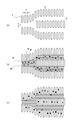
- FIG. 2 is a model diagram conceptually showing the positional relationship between the pore 2 and the communication hole 3 of the artificial soil particle 10 of the present invention.
- FIG. 2 models the internal structure of the artificial soil particle 10 shown in FIG. 1, but does not reflect the actual internal structure of the artificial soil particle 10 as it is.
- the pores 2 are dispersedly arranged around the communication holes 3.
- the pores 2 are connected to the communication holes 3 and the pores 2 connected to the communication holes 3. Is present substantially throughout the periphery of the communication hole 3. For example, referring to FIG. 2A, a large number of pores 2 of size x are connected to a communication hole 3 of size y, and a large number of pores 2 extend along the entire length of the communication hole 3.
- the existing state is shown.
- Such a specific positional relationship between the pore 2 and the communication hole 3 is a great feature of the present invention.
- This specific positional relationship may be approximately half or more of the pores 2 and the communication holes 3.
- FIG. 2A for the sake of space, a specific positional relationship between the pore 2 and the communication hole 3 is shown two-dimensionally, but the actual artificial soil particle 10 has a three-dimensional spread.
- the above-described specific positional relationship is formed.
- the conditions for causing the specific positional relationship between the pores 2 and the communication holes 3 to appear have not yet been clarified yet.
- a material having high crystallinity can be selected as the filler 1
- a material having a unique crystal structure is selected as the filler 1
- a plurality of types are used as the filler 1 in a specific combination, the crystal structure or layer structure of the filler 1 is controlled, or the filler 1 is oriented. Possibility to make it appear stronger by processing, adding a specific additive when granulating the filler 1 or optimizing the granulation method (granulation conditions) of the filler 1 It is thought that there is.
- FIGS. 2 (a) to (c) show the state in which moisture W and nutrients K, N, and P are taken into the artificial soil particles 10 from outside.
- nutrient K represents potassium
- nutrient N represents nitrogen
- nutrient P represents phosphorus.
- the artificial soil particles 10 are connected to the communication holes 3 and the communication holes 3.
- the connecting pores 2 are voids.
- the artificial soil particles 10 come into contact with the moisture W containing the nutrients K, N, and P, the moisture W and the nutrients K, N, and P are first taken into the communication holes 3 as shown in FIG.
- the communication hole 3 is sufficiently wet, as shown in FIG. 2 (c), among the water W and the nutrients K, N, and P taken into the communication hole 3, the nutrients K, N, and P are the communication holes. 3 to the pore 2.
- the artificial soil particle 10 of the present invention nutrients K, N, and P are mainly taken into the pores 2 and moisture W is held in the communication holes 3 so that the pores 2 are mainly responsible for fertilization.
- the communication hole 3 is responsible for water retention.
- the pores 2 and the communication holes 3 of the artificial soil particles 10 are preferably configured so that the total volume of the communication holes 3 is larger than the total volume of the pores 2. This is to ensure sufficient water retention of the communication holes 3 and to smoothly move nutrients from the communication holes 3 to the pores 2. Moreover, since the artificial soil particle 10 will become lightweight if the total volume of the communicating hole 3 becomes larger than the total volume of the pore 2, the bulk density will become small and the handling as artificial soil will also become easy. In order to make the total volume of the communication hole 3 larger than the total volume of the pore 2, the filler 1 is combined in a three-dimensional network.
- the filler 1 when the filler 1 is granulated, for example, a porous binder is used, or the filler 1 is dried by a freeze-drying method or the like. This can be done by combining them.
- the plurality of fillers 1 are three-dimensionally bonded while forming a large number of voids, and a filler aggregate (artificial soil particle 10) having a three-dimensional network structure is formed.
- Filler aggregates combined in a three-dimensional network form are suitably used as artificial soil particles 10 that have the strength necessary for cultivation of root vegetables because they are low in bulk density and are light and structurally stable. it can.
- the basic performance as soil such as water retention, fertilizer retention, drainage, and breathability is good, and artificial soil with high added value can be obtained.
- the strength of the artificial soil particle 10 can be evaluated by a volume change rate by repeatedly applying a compressive load.
- the artificial soil particle 10 of the present invention is designed such that the volume change rate after repeated application of a compressive load of 25 KPa is 20% or less. A preferable volume change rate is 15% or less.
- the volume change rate exceeds 20%, the artificial soil particles 10 are easily pulverized when the planter is filled with artificial soil or seedlings are transplanted, and the structure of the artificial soil particles 10 (the pores 2 of the filler 1). May be dispersed around the communication holes 3 between the plurality of fillers 1, and the filler 1 may be lost in a three-dimensional network structure. As a result, the balance between water retention and fertilizer retention is lost. Further, when the structure of the artificial soil particles 10 is lost, the artificial soil is easily compacted, which may adversely affect the cultivation of root vegetables.
- the artificial soil particle 10 of the present invention is suitable for cultivation of root vegetables, since it has excellent water retention as artificial soil, it is used for the cultivation of leafy vegetables that have been mainly hydroponically cultivated so far. It is also possible to apply.
- the water retention capacity of the artificial soil can be evaluated based on the water retention capacity.
- the water retention amount is obtained as a water retention amount (%) per 100 mL of artificial soil particles.
- the artificial soil particle 10 of the present invention has a unique structure in which the pores 2 of the filler 1 are dispersedly arranged around the communication holes 3 between the plurality of fillers 1 and the filler 1 is combined in a three-dimensional network.
- the water retention amount can be set to 20 to 70%.
- the air permeability can be expressed by the gas phase rate of the artificial soil in a dry state.
- the gas phase rate of the artificial soil using the artificial soil particles 10 of the present invention can be set to be 20 to 80%.
- a preferable gas phase rate is 30 to 80%, and a more preferable gas phase rate is 30 to 70%.
- the gas phase rate is less than 20%, the amount of air supplied to the plant root is insufficient, and when it exceeds 80%, there is a possibility that sufficient water retention cannot be secured.
- One method for improving the water retention of the communication hole 3 is to introduce a water retention material into the communication hole 3 of the artificial soil particle 10.
- the water retention material can be introduced, for example, by filling the entire communication hole 3 with a water retention material or coating the surface of the communication hole 3 with a film of the water retention material.
- the water retaining material only needs to be present in at least a part of the communication hole 3.
- the water-retaining material is introduced by mixing and granulating a water-retaining polymer material, or preparing a polymer solution by dissolving the water-retaining polymer material in a solvent, It is carried out by impregnating the artificial soil particles 10.
- polymer materials that can be used as water-retaining materials include synthetic polymer water-retaining properties such as polyacrylate polymers, polysulfonate polymers, polyacrylamide polymers, polyvinyl alcohol polymers, and polyalkylene oxide polymers.
- synthetic polymer water-retaining properties such as polyacrylate polymers, polysulfonate polymers, polyacrylamide polymers, polyvinyl alcohol polymers, and polyalkylene oxide polymers.
- natural polymeric water-retaining materials such as materials, polyaspartate-based polymers, polyglutamate-based polymers, polyalginate-based polymers, cellulose-based polymers, and starches. These water retaining materials can be used in combination of two or more.
- the solvent that dissolves the polymer material which is a water-retaining material, has a high solubility depending on the polymer material used, that is, a combination in which the solubility parameter (SP value) is close between the polymer material and the solvent is appropriate. Selected. For example, a combination in which the difference between the SP value of the polymer material and the SP value of the solvent is 5 or less (eg, a combination of nitrocellulose having an SP value of about 10 and methanol having an SP value of about 14.5) Is selected.
- solvents include methanol, ethanol, isopropanol, butanol, ethyl acetate, acetone, methyl ethyl ketone, methyl isobutyl ketone. These solvents can be used in combination of two or more.
- Another method for improving the water retention of the communication hole 3 is to use a water retention filler for a part or all of the filler 1 as a raw material when the artificial soil particles 10 are prepared.
- the generated artificial soil particles 10 themselves have water retention properties, so that a special post-treatment for improving the water retention properties is not necessary.
- Hydrophilic fillers and porous granular materials can be used as water retention fillers, and examples of hydrophilic fillers include zeolite, smectite minerals, mica minerals, talc, silica, and double hydroxides.
- the porous particulate material include foamed glass, porous metal, porous ceramic, polymer porous body, and hydrophilic fiber.
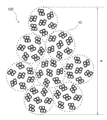
- FIG. 3 is an explanatory diagram of the artificial soil aggregate 100 of the present invention.
- the artificial soil aggregate 100 which aggregated the artificial soil particle 10 using the zeolite 1a shown to Fig.1 (a) is illustrated.
- the artificial soil aggregate 100 has a cluster structure in which a plurality of artificial soil particles 10 are connected.
- the cluster structure is obtained by bonding a plurality of artificial soil particles 10 with a secondary binder.
- the secondary binder used for the agglomeration can be the same as the binder (primary binder) used in the formation of the artificial soil particles 10, but may be a different type of binder.
- the size of the artificial soil aggregate 100 (average value of the size w of the artificial soil aggregate 100 shown in FIG. 3) is 0.4 to 20 mm, preferably 0.5 to 18 mm, more preferably 1 ⁇ 15 mm.
- the size of the artificial soil aggregate 100 is less than 0.4 mm, the gap between the artificial soil particles 10 constituting the artificial soil aggregate 100 is reduced and the drainage performance is reduced, so that the plant to be cultivated from the roots. There is a risk that it may be difficult to absorb oxygen.
- the size of the artificial soil particle 10 exceeds 20 mm, the drainage property becomes excessive, and the plant may not easily absorb moisture, or the artificial soil aggregate 100 may be sparse and the plant may fall down. There is.
- the size of the artificial soil aggregate 100 is measured using, for example, an optical microscope observation and an image processing method. In the present embodiment, the size of the artificial soil aggregate 100 is measured by the measurement method using the image processing described above, similarly to the size of the communication hole 3 and the particle size of the artificial soil particle 10.
- the artificial soil aggregate 100 obtained by agglomerating the artificial soil particles 10 of the present invention has an excellent balance between water retention and fertilizer retention, and appropriately supplies moisture and nutrients to the plant to be cultivated. Can be supplied. Therefore, the artificial soil aggregate 100 of the present invention is useful as artificial soil that does not require maintenance and is easy to handle.
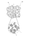
- FIG. 4 is an explanatory diagram of the artificial soil molded body 150 of the present invention.
- a dotted circle shown in FIG. 4 is a partially enlarged view of the artificial soil particle 10 constituting the artificial soil molded body 150, and represents a cross section of the artificial soil particle 10.
- the artificial soil molded body 150 is obtained by molding a plurality of artificial soil particles 10 into a predetermined shape.
- the artificial soil molded body 150 can be processed into various shapes such as a sheet shape, a block shape, a plate shape, a belt shape, a spherical shape, a rod shape, and an indeterminate shape depending on applications.
- the artificial soil molded body 150 has a certain gap 11 between adjacent artificial soil particles 10. Since this gap 11 allows air and water to pass therethrough, excess water can be discharged while holding water necessary for the plant. When the artificial soil molded body 150 is in a wet state, excess moisture is discharged from the gap 11, and when the artificial soil molded body 150 is in a dry state, moisture existing in the surroundings due to the capillary phenomenon of the gap 11. Can suck up. As described above, the artificial soil molded body 150 achieves excellent air permeability and drainage by the gaps 11 formed between the adjacent artificial soil particles 10. In addition, the gap 11 provides a space for the plant roots to grow, so that the plant roots can be easily stretched, and thus the plant growth can be promoted.
- Examples of the molding method of the artificial soil molded body 150 include a method in which a secondary binder is added to the artificial soil particles 10 and kneaded, and the mixture is adjusted to a predetermined shape and dried.
- a secondary binder the same binder (primary binder) used in the formation of the artificial soil particles 10 can be used, but different types of binders may be used.
- the addition amount of the secondary binder can be, for example, 1 to 30% by weight.
- the added amount of the secondary binder is less than 1% by weight, the binding force between the artificial soil particles 10 may be insufficient, and if the added amount of the secondary binder exceeds 30% by weight, the gap between the artificial soil particles 10 11 becomes small, and there is a possibility that the drainage property of the artificial soil molded body 150 may deteriorate.
- a flexible granular material for example, a crushed product of polyurethane foam
- the elongation of the root of the plant is not hindered, and the gap between the artificial soil particles 10 constituting the artificial soil molded body 150 can be expanded in accordance with the elongation of the root.
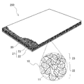
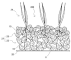
- FIG. 5 is an explanatory diagram of the greening sheet 200 of the present invention.
- FIG. 6 is a partial cross-sectional view showing a state in which the plant 24 is planted on the greening sheet 200 shown in FIG.
- the greening sheet 200 is obtained by laying the artificial soil molded body 150 described above in a sheet shape.
- FIG. It has the structure provided with the water-permeable sheet 20 to support and the planting base layer 21 which laminated
- the planting base layer 21 is formed in two layers as shown in FIG.
- a drainage layer 22 in which artificial soil particles 10 having a large particle size are stacked is formed in a lower layer, and a water retention layer 23 in which artificial soil particles 10 having a small particle size are stacked is formed in an upper layer.
- the water-permeable sheet 20 is comprised with the material which can permeate
- the plant 24 can use water stored in the upper water retention layer 23.
- the water retention layer 23 retains moisture in the communication holes 3 of the artificial soil particles 10 and also retains moisture in the gaps 11 where the artificial soil particles 10 are densely formed. Can be supplied.
- excess water contained in the gap 11 can be discharged while retaining water necessary for the plant 24 in the artificial soil particle 10, so that air permeability is secured to the root of the plant 24.
- root rot of the plant 24 can be prevented.
- the drainage layer 22 is roughly filled with the artificial soil particles 10, the roots of the plants 24 are easily stretched, and the plants 24 can be prevented from falling down.
- the thickness of the greening sheet 200 can be easily adjusted and handled easily. For this reason, the workability
- Many kinds of plants 24 can be cultivated by appropriately adjusting the thickness of the greening sheet 200.
- the greening sheet 200 can adjust the thickness of the sheet more widely by using the artificial soil particles 10 to which the water retention material is added.
- the thickness of the greening sheet 200 is different depending on the type of plant, that is, the depth of the root when used on the roof of a building or a house, or the floor of a balcony. Is preferable, and 30 to 100 mm is more preferable.
- the structure of the planting base layer 21 can be appropriately changed depending on the use place and use form of the greening sheet 200.
- the planting base layer 21 may be divided into three or more layers to change the density of the artificial soil particles 10, and the planting base layer 21 has a continuous density gradient in the thickness direction from the upper layer to the lower layer. You may form so that it may have. Or you may form so that the planting base layer 21 may become the same density in the thickness direction.
- FIG. 7 is an explanatory diagram of the wall surface greening panel 300 of the present invention.
- the wall surface greening panel 300 is obtained by holding the above artificial soil molded body 150 on the frame body 30.
- the artificial soil molded body 150 is disposed in the recess 31 formed in the frame body 30.
- the artificial soil molded body 150 is provided with, for example, a plurality of hooks (not shown) in the recess 31 so that the artificial soil molded body 150 does not fall from the frame 30, and the artificial soil molded body 150 is held by being hooked on the hooks. ing.
- the artificial soil molded body 150 is planted with plants 24 throughout, and when the plants 24 grow, the front surface of the wall greening panel 300 is substantially covered with the plants 24 and is greened.
- the frame 30 used for the wall greening panel 300 is made of a lightweight material having water resistance and corrosion resistance so that it can be used outdoors.
- the material of the frame 30 include synthetic resin materials such as polyethylene resin, polystyrene resin, PET resin, and ABS resin, lightweight metal materials such as aluminum alloy and magnesium alloy, and wood such as cedar, cypress, and bamboo. .
- the frame body 30 used for the wall surface greening panel 300 of the present embodiment is configured to be rectangular when viewed from the front.
- the shape and structure of the frame body 30 is such that the wall surface greening is performed. It can be changed as appropriate according to the situation of the location.
- the structure of the artificial soil molded body 150 is stable, if the artificial soil molded body 150 is light to some extent, a reinforcing tape instead of the frame body 30 is wrapped around the artificial soil molded body 150.
- the configuration of the frame body 30 can be simplified or omitted.
- wall greening suitable for the situation of the place where the wall greening panel 300 is installed can be performed by combining the wall greening panels 300 of various forms.
- the wall surface greening panel 300 when the wall surface greening panel 300 is attached to a vertical wall surface, when water is sprayed on the wall surface greening panel 300, the water held in the artificial soil molded body 150 falls by gravity.
- the portion located above the wall greening panel 300 in the vertical direction is likely to dry, and the portion located below the vertical direction may be excessively watery due to water falling from above. Therefore, in the wall greening panel 300, the artificial soil is provided with a density gradient so that the density of the artificial soil particles 10 positioned in the upper vertical direction is dense and the density of the artificial soil particles 10 positioned in the lower vertical direction is coarse. It is also possible to configure the molded body 150.
- the wall surface greening panel 300 is configured using such an artificial soil molded body 150, the unevenness of moisture held between the upper and lower sides in the vertical direction of the wall surface greening panel 300 is reduced, and plants are grown evenly on the entire wall surface. It becomes possible to make it.
- FIG. 8 is an explanatory diagram of the gardening block 400 of the present invention.
- the horticultural block 400 is obtained by stacking the above artificial soil molded body 150 into a block shape.
- the artificial soil molded body 150 is configured in the shape of a container for plant cultivation. It is.
- the molding method of the artificial soil molded body 150 can be used.
- a concave planting portion 40 for planting a plant is formed.
- the gardening block 400 can be commercialized as a plant pot in which artificial soil and plants are integrated.
- the horticultural block 400 can be added with a synthetic polymer material or a natural polymer material that can function as a water retention material when the artificial soil particles 10 are molded so that the irrigated water does not leak to the outside.
- the same water retaining material as that used for the artificial soil particles 10 can be used as the water retaining material, but a different type of water retaining material may be used.
- the horticultural block 400 can also be configured with a two-layer structure including an outer portion and an inner portion.
- a layer with high water retention is formed by adding a water retention material to the outer side
- a layer with high fertilization is formed by adding a material having ion exchange capacity to the inner side.
- water does not leak to the outside of the horticultural block 400 even when irrigated while ensuring the water permeability and air permeability of the inner part.
- a fertilizer is added to the planting part 40 of the gardening block 400, since an inner part has fertilizer, the plant can absorb nutrients reliably.
- the artificial soil molded body, the greening sheet, the wall greening panel, and the horticultural block of the present invention are configured based on the artificial soil particles and the artificial soil aggregate of the present invention. Therefore, in the examples, the artificial soil particles and artificial soil aggregates of the present invention will be particularly described.
- the artificial soil particles of the present invention were prepared by different granulation methods (granulation method, pulverization method, gelation method). Further, as Example 4, the artificial soil particles of the present invention were aggregated to prepare the artificial soil aggregate of the present invention. The characteristics of artificial soil particles and artificial soil aggregates were evaluated by the methods shown in the following (1) to (6).
- Pore size The pore size of the pores of the filler constituting the artificial soil particles was measured by a gas adsorption method.
- the pore diameter (pore diameter distribution) of the communication holes formed between the plurality of fillers was measured by a mercury intrusion method. The pore size distribution will be described in detail later in “Pore size distribution of artificial soil particles”.
- Cation exchange capacity An artificial soil particle extract was prepared using a general-purpose extraction and filtration device “CEC-10 Ver.2” manufactured by Fujihira Kogyo Co., Ltd., and this was used as a sample for cation exchange capacity measurement. did. Then, the cation exchange capacity (CEC) of the artificial soil particles was measured using a comprehensive soil and crop body analyzer “SFP-3” manufactured by Fujihira Kogyo Co., Ltd.
- Anion exchange capacity 20 mL of 0.05 M calcium nitrate solution was added to 2 g of the artificial soil particles and stirred for 1 hour. The solution was centrifuged (10,000 rpm) at room temperature for 1 minute, and the supernatant was used as a measurement sample. About the sample for a measurement, the light absorbency of wavelength 410nm was measured using the ultraviolet visible spectrophotometer, and the calcium nitrate density
- AEC anion exchange capacity
- the strength of the artificial soil particles was evaluated based on the volume change rate due to repeated addition of compressive load.
- the volume change rate was determined by the following method. A sample cylinder (inner diameter: about 5 cm, height: about 5 cm, volume: 100 mL) for soil evaluation is filled with 100 mL of artificial soil as a sample, and a cylindrical weight (weight: 5 kg) slightly smaller in diameter than the sample cylinder was slowly placed on top of the sample. In that state, it was left for 60 seconds, and the weight was removed. These operations were repeated 10 times (repeated compression load 25 KPa).
- Vapor rate A sample was prepared by immersing artificial soil composed of artificial soil particles in tap water for 24 hours to obtain a saturated water content, and the sample was allowed to stand for another hour. After flowing down the weight water of the sample, it was collected in a 100 mL sample cylinder while maintaining the shape as much as possible, and set in a digital real volume measuring device “DIK-1150” manufactured by Dairika Kogyo Co., Ltd. Was measured.
- Example 1 Granulation method Zeolite was used as a filler and polyethylene emulsion was used as a binder. 100 parts by weight of an artificial zeolite “Ryukyu Light 600” manufactured by Ecowell Co., Ltd. and 5 parts by weight of a polyethylene emulsion “Sepoljon (registered trademark) G” manufactured by Sumitomo Seika Co., Ltd. are mixed and granulated with stirring. And then dried at 120 ° C. for 24 hours and classified with a sieve to obtain artificial soil particles with 2 mm over and 4 mm under.
- an artificial zeolite “Ryukyu Light 600” manufactured by Ecowell Co., Ltd.
- the obtained artificial soil particles had a plurality of fillers having pores in the order of sub-nm order to sub- ⁇ m order, and communication holes in the order of sub- ⁇ m order to sub-mm order were formed between the fillers. . Further, the pores were dispersedly arranged over the entire periphery of the communication hole.
- the artificial soil particles had a cation exchange capacity of 18 meq / 100 cc. Furthermore, the strength (volume change rate) of the artificial soil using the artificial soil particles was 15%, the water retention amount (water retention amount) was 28%, and the gas phase rate was 35%.
- Example 2 Grinding method Hydrotalcite was used as a filler and polyethylene emulsion was used as a binder. 100 parts by weight of reagent hydrotalcite manufactured by Wako Pure Chemical Industries, Ltd. and 5 parts by weight of polyethylene emulsion “Sepoljon (registered trademark) G” manufactured by Sumitomo Seika Co., Ltd. are mixed with stirring, and the mixture is used as a dryer. It was introduced and dried at 120 ° C. for 24 hours to obtain a block-like product. This block-like product was pulverized using a mortar and pestle and classified by sieving to obtain artificial soil particles having a 2 mm over and a 4 mm under.
- the obtained artificial soil particles had a plurality of fillers having pores in the order of sub-nm order to sub- ⁇ m order, and communication holes in the order of sub- ⁇ m order to sub-mm order were formed between the fillers. . Further, the pores were dispersedly arranged over the entire periphery of the communication hole.
- the anion exchange capacity of the artificial soil particles was 15 meq / 100 cc. Furthermore, the strength (volume change rate) of the artificial soil using the artificial soil particles was 12%, the water retention amount (water retention amount) was 25%, and the gas phase rate was 37%.
- Example 3 Gelling method Zeolite and hydrotalcite were used as fillers, sodium alginate was used as an alginate, and a 5% calcium chloride aqueous solution was used as an aqueous polyvalent metal ion solution.
- a reagent sodium alginate manufactured by Wako Pure Chemical Industries, Ltd. was dissolved in water to prepare an aqueous solution having a concentration of 0.5%, and an artificial zeolite “Ryukyu Light 600 manufactured by Ecowell Co., Ltd. was added to 100 parts by weight of an aqueous 0.5% sodium alginate solution. 10 parts by weight and 10 parts by weight of a reagent hydrotalcite manufactured by Wako Pure Chemical Industries, Ltd. were added and mixed.
- the mixed solution was dropped into a 5% calcium chloride aqueous solution at a rate of 1 drop / second. After the dropped droplets were gelled, the particulate gel was recovered, washed with water, and dried for 24 hours with a dryer set at 55 ° C. The dried particulate gel was classified by sieving to obtain artificial soil particles of 2 mm over and 4 mm under.
- the obtained artificial soil particles had a plurality of fillers having pores in the order of sub-nm order to sub- ⁇ m order, and communication holes in the order of sub- ⁇ m order to sub-mm order were formed between the fillers. . Further, the pores were dispersedly arranged over the entire periphery of the communication hole.
- the artificial soil particles had a cation exchange capacity of 14 meq / 100 cc and an anion exchange capacity of 15 meq / 100 cc. Furthermore, the strength (volume change rate) of the artificial soil using the artificial soil particles was 13%, the water retention amount (water retention amount) was 26%, and the gas phase rate was 33%.
- Example 4 Artificial soil aggregate 100 parts by weight of a pulverized product of artificial soil particles obtained in Example 3 and a vinyl acetate resin adhesive “Bond (registered trademark)” manufactured by Konishi Co., Ltd. as a secondary binder. 5 parts by weight for woodworking were mixed, the mixture was introduced into a granulator and agglomerated to obtain an artificial soil aggregate.
- the obtained artificial soil aggregate had a particle size of 3 to 18 mm and a cluster structure in which a plurality of artificial soil particles were connected.
- FIG. 9 is a graph showing the measurement results of the pore size distribution of the artificial soil particles or artificial soil aggregates of the present invention by mercury porosimetry.
- the pore size distribution was measured by (a) freeze-drying artificial soil particles (artificial soil particles obtained by changing the drying method to freeze-drying method in Example 3), and (b) artificial soil particles (0.1-0.
- the peak near about 30 nm is presumed to be a minute gap formed between fillers, and the peak near about 2 ⁇ m is presumed to be a communicating hole.
- the peak was confirmed by three places, about 50 nm vicinity, about 0.65 micrometer vicinity, and about 20 micrometer vicinity.
- a peak near about 50 nm is presumed to be a minute gap formed between fillers, and a peak near about 0.65 ⁇ m is presumed to be a communicating hole.
- the peak of about 20 micrometers is equivalent to the clearance gap between the particles by agglomeration, and this clearance gap can also be considered as a kind of communicating hole.
- the artificial soil particle or artificial soil aggregate of the present invention has sub- ⁇ m order to sub-mm order communication holes, and is combined with the sub-nm order to sub- ⁇ m order pores of the filler. It was confirmed to have a unique porous structure with two types of size distributions.
- the artificial soil particles and artificial soil aggregates of the present invention can be used for artificial soil used in plant factories, etc., but as other uses, facility horticultural soil, greening soil, molded soil, soil improvement It can also be used as an agent and soil for interiors.
- the artificial soil molded body, the greening sheet, the wall greening panel, and the horticultural block of the present invention can be used for greening and planting on a rooftop or balcony of a building or a house.
Landscapes
- Life Sciences & Earth Sciences (AREA)
- Chemical & Material Sciences (AREA)
- Organic Chemistry (AREA)
- Geology (AREA)
- Environmental Sciences (AREA)
- Inorganic Chemistry (AREA)
- General Life Sciences & Earth Sciences (AREA)
- Pest Control & Pesticides (AREA)
- Soil Sciences (AREA)
- Engineering & Computer Science (AREA)
- Chemical Kinetics & Catalysis (AREA)
- Materials Engineering (AREA)
- Cultivation Of Plants (AREA)
Description
サブnmオーダー乃至サブμmオーダーの細孔を有するフィラーが複数集合してなる人工土壌粒子であって、
前記フィラーの間にサブμmオーダー乃至サブmmオーダーの連通孔が形成され、
前記連通孔が外部から水分及び養分を取り込むとともに、前記細孔が前記連通孔から前記養分を受け取り可能なように、前記細孔が前記連通孔の周囲に分散配置されていることにある。
このように、本構成の人工土壌粒子は、一つの粒子内において、細孔と連通孔との間に特定の関係を持たせており、細孔と連通孔とで異なる機能を分担させているため、土壌としての基本性能をバランスよく発揮し得る(すなわち、保水性と保肥性とのバランスに優れた)、高品質で機能的な人工土壌粒子を実現することができる。また、このような人工土壌粒子は、栽培対象の植物に対して水分や養分を適切に供給できるので、メンテナンスに手間が掛からず、取り扱いが容易なものとなる。
前記連通孔の全容積が前記細孔の全容積より大きくなるように、前記フィラーは三次元ネットワーク状に結合されていることが好ましい。
前記連通孔の少なくとも一部に保水性材料が導入されるとともに、前記細孔にイオン交換能を付与してあることが好ましい。
前記細孔の孔径が0.2~800nmであり、前記連通孔の孔径が0.1~500μmであることが好ましい。
0.2~10mmの粒径を有することが好ましい。
前記何れか一つに記載の人工土壌粒子を団粒化したことにある。
前記何れか一つに記載の人工土壌粒子を成型してなることにある。
前記の人工土壌成型体をシート状に敷設したことにある。
前記の人工土壌成型体を枠体で保持したことにある。
前記の人工土壌成型体をブロック状に積層したことにある。
図1は、本発明の人工土壌粒子10を概念的に表した説明図である。図1(a)は、フィラー1として、多孔質天然鉱物であるゼオライト1aを使用した人工土壌粒子10を例示したものである。図1(b)は、フィラー1として、層状天然鉱物であるハイドロタルサイト1bを使用した人工土壌粒子10を例示したものである。なお、図1中に示す記号x、y及びzは、後述する細孔2、連通孔3及び人工土壌粒子10のサイズを夫々表しているが、図面上でのx、y及びzの大きさは実際のサイズを反映したものではない。
フィラー1が本実施形態に示すゼオライト1aやハイドロタルサイト1bのような無機天然鉱物である場合、複数のフィラー1を集合して粒状物(人工土壌粒子10)を構成するために、バインダーを用いて粒状化を行うことができる。バインダーを用いた人工土壌粒子10の形成は、フィラー1にバインダーや溶媒等を加えて混合し、混合物を造粒機に導入し、転動造粒、流動層造粒、攪拌造粒、圧縮造粒、押出造粒、破砕造粒、溶融造粒、噴霧造粒等の公知の造粒法により行うことができる。得られた造粒体は、必要に応じて乾燥及び分級が行われ、人工土壌粒子10が完成する。また、フィラー1にバインダーを加え、さらに必要に応じて溶媒等を加えて混練し、これを乾燥してブロック状にしたものを、乳鉢及び乳棒、ハンマーミル、ロールクラッシャー等の粉砕手段で適宜粉砕して粒状物とすることも可能である。この粒状物は、そのまま人工土壌粒子10として用いることもできるが、篩にかけて所望の粒径に調整することが好ましい。
上に例示した各方法によって得られた粒状物は、サブnmオーダー乃至サブμmオーダーの細孔2を有するフィラー1が複数集合してなる本発明の人工土壌粒子10を構成する。人工土壌粒子10の粒径(図1に示す人工土壌粒子10のサイズzの平均値)は、0.2~10mmであり、好ましくは0.5~5mmであり、より好ましくは1~5mmである。人工土壌粒子10の粒径の調整は、例えば、篩による分級で行うことができる。人工土壌粒子10を構成する複数のフィラー1の間には連通孔3が形成される。人工土壌粒子10の粒径が0.2mm未満の場合、人工土壌粒子10間の間隙が小さくなって排水性が低下することにより、栽培する植物が根から酸素を吸収し難くなる虞がある。一方、人工土壌粒子10の粒径が10mmを超えると、人工土壌粒子10間の間隙が大きくなって排水性が過剰になり過ぎることにより、植物が水分を吸収し難くなったり、人工土壌粒子10が疎になって植物が横倒れする虞がある。連通孔3のサイズ(図1に示す隣接するフィラー1間の距離yの平均値)は、フィラー1やバインダーの種類、組成、造粒条件により変化し得るが、サブμmオーダー乃至サブmmオーダーとなる。例えば、連通孔3のサイズは、0.1~500μm程度に設定可能であるが、フィラー1が、図1(a)に示すゼオライト1a、又は図2(b)に示すハイドロタルサイト1bであり、高分子ゲル化剤を使用した場合、連通孔3のサイズは、0.1~20μmとなる。連通孔3のサイズは、測定対象の状態に応じて、ガス吸着法、水銀圧入法、小角X線散乱法、画像処理法等を用いて、又はこれらの方法を組み合わせて、最適な方法により測定することができる。人工土壌粒子10の粒径は、例えば、光学顕微鏡観察及び画像処理法を用いて測定することができる。本実施形態では、以下の測定法により、連通孔3のサイズ、及び人工土壌粒子10の粒径を測定した。先ず、測定対象の人工土壌粒子をスケールとともに顕微鏡で観察し、その顕微鏡画像を画像処理ソフト(二次元画像解析処理ソフトウェア「WinROOF」、三谷商事株式会社製)を使用して取得する。画像から100個の人工土壌粒子を選択し、連通孔又は人工土壌粒子の輪郭をトレースする。トレースした図形の周長から、相当円の直径を算出する。夫々の連通孔又は人工土壌粒子から求めた相当円の直径(100個)の平均を平均サイズ(単位:ピクセル)とする。そして、平均サイズを顕微鏡画像中のスケールと比較し、単位長さ(μmオーダー乃至mmオーダー)に変換して、連通孔のサイズ又は人工土壌粒子の粒径を算出する。
本発明の人工土壌粒子10は、細孔2と連通孔3とが特定の位置関係を有するため、土壌としての基本性能(保水性及び保肥性)のバランスに優れた高品質で機能的な人工土壌とすることができる。ここで、人工土壌粒子10が有する保水性及び保肥性のメカニズムを、図2(a)~(c)を参照しながら詳細に説明する。図2(a)~(c)は、人工土壌粒子10に外部から水分W、及び養分K、N、Pが取り込まれる様子を段階的に示したものである。ここで、養分Kはカリウム分、養分Nは窒素分、養分Pはリン分を表している。
人工土壌粒子10の細孔2及び連通孔3は、連通孔3の全容積が細孔2の全容積より大きくなるように構成されることが好ましい。これは、連通孔3の保水性を十分に確保するとともに、連通孔3から細孔2への養分の移動がスムーズに行われるようにするためである。また、連通孔3の全容積が細孔2の全容積より大きくなれば、人工土壌粒子10が軽量となるため、嵩密度が小さくなり、人工土壌としての取り扱いも容易となる。連通孔3の全容積を細孔2の全容積より大きくするためには、フィラー1を三次元ネットワーク状に結合する。これは、例えば、フィラー1を粒状化する際、例えば、多孔性のバインダーを使用したり、凍結乾燥法などで乾燥させたり、フィラー1とバインダーとの混合物に空気を含ませながらフィラー1を互いに結合させることによって行うことができる。この場合、複数のフィラー1は多数の空隙を形成しながら三次元的に結合し、三次元ネットワーク状の構造を有するフィラー集合体(人工土壌粒子10)が形成される。三次元ネットワーク状に結合したフィラー集合体は、嵩密度が低く軽量でありながら構造的にも安定しているため、根菜類の栽培に必要な強度が確保された人工土壌粒子10として好適に利用できる。また、内部に有する多数の空隙のため、保水性、保肥性、排水性、通気性等の土壌としての基本性能が良好なものとなり、付加価値の高い人工土壌とすることができる。
本発明の人工土壌粒子10は、さらに団粒化して人工土壌団粒体の形態で人工土壌として利用することも可能である。図3は、本発明の人工土壌団粒体100の説明図である。ここでは、図1(a)に示すゼオライト1aを使用した人工土壌粒子10を団粒化した人工土壌団粒体100を例示する。
本発明の人工土壌粒子10は、任意の形状に成型した人工土壌成型体として利用することができる。図4は、本発明の人工土壌成型体150の説明図である。図4中に示す点線円は、人工土壌成型体150を構成する人工土壌粒子10の一部拡大図であり、人工土壌粒子10の断面を表している。人工土壌成型体150は、複数の人工土壌粒子10を所定の形状に成型したものである。人工土壌成型体150は、用途に応じて、シート状、ブロック状、板状、帯状、球状、棒状、不定形状等、種々の形状に加工することができる。人工土壌成型体150は、隣接する人工土壌粒子10の間に一定の隙間11を有している。この隙間11は、空気及び水が通過することができるため、植物に必要な水分を保持しながら余分な水分を排出することができる。人工土壌成型体150が湿潤状態となった場合、隙間11から余分な水分を排出し、人工土壌成型体150が乾燥状態となった場合には、隙間11の毛細管現象により、周囲に存在する水分を吸い上げることができる。このように、人工土壌成型体150は、隣接する人工土壌粒子10の間に形成される隙間11によって、優れた通気性及び排水性を実現している。また、隙間11は、植物の根が成長するための空間を提供するため、植物の根が張り易く、ひいては植物の成長を促すことができる。
図5は、本発明の緑化用シート200の説明図である。図6は、図5に示した緑化用シート200に植物24を植えた状態を示す一部断面図である。緑化用シート200は、上述の人工土壌成型体150をシート状に敷設したものであり、本実施形態では、図5に示すように、灌水時の水を適宜透過させつつ、人工土壌粒子10を支持する透水性シート20と、透水性シート20の上に形成される人工土壌粒子10を積層した植栽基盤層21とを備えた構成を有する。植栽基盤層21は、図5に示すように、2層に形成されている。植栽基盤層21には、下層に粒度の大きい人工土壌粒子10を積層した排水層22が形成され、上層に粒度の小さい人工土壌粒子10を積層した保水層23が形成されている。植栽基盤層21の成型方法としては、上記人工土壌成型体150の成型方法が用いられる。透水性シート20は、植栽基盤層21から排水される水分を透過できる材質で構成され、例えば、ポリエチレン、ポリプロピレン等の合成繊維からなる不織布が挙げられる。
図7は、本発明の壁面緑化パネル300の説明図である。壁面緑化パネル300は、上述の人工土壌成型体150を枠体30に保持したものである。本実施形態では、図7に示すように、枠体30に形成した凹部31に人工土壌成型体150が配置されている。人工土壌成型体150は、枠体30から落下しないように、例えば、凹部31に図示しない複数のフックが設けられており、このフックに人工土壌成型体150が引っ掛かることで保持されるようになっている。人工土壌成型体150には、全体に亘って植物24が植えられており、植物24が成長すると、壁面緑化パネル300の前面が植物24で略覆われて緑化される。壁面緑化パネル300に使用する枠体30は、屋外での使用に耐え得るように、耐水性及び耐腐食性を有し、且つ軽量な素材で構成することが好ましい。枠体30の素材としては、例えば、ポリエチレン樹脂、ポリスチレン樹脂、PET樹脂、ABS樹脂などの合成樹脂材料、アルミニウム合金、マグネシウム合金などの軽量金属材料、スギ、ヒノキ、竹などの木材等が挙げられる。
図8は、本発明の園芸用ブロック400の説明図である。園芸用ブロック400は、上述の人工土壌成型体150をブロック状に積層したものであり、本実施形態では、図8に示すように、人工土壌成型体150を植物栽培用の容器の形状に構成してある。園芸用ブロック400の成型方法としては、上記人工土壌成型体150の成型方法を用いることができる。園芸用ブロック400の上部中央付近には、植物を植えるための凹状の植栽部40が形成されている。これにより、園芸用ブロック400は、人工土壌と植物とを一体化させた植物ポットとして製品化することができる。園芸用ブロック400は、灌水した水が外部に漏れないように、人工土壌粒子10を成型する際に保水性材料として機能し得る合成高分子材料や天然高分子材料を添加することも可能である。この場合、保水性材料は人工土壌粒子10に用いた保水性材料と同じものを使用できるが、異なる種類の保水性材料であっても構わない。園芸用ブロック400の対漏水性を向上させることにより、室内においても好適に利用することが可能となる。
人工土壌粒子又は人工土壌団粒体を篩によって予め所定の粒径に分級し、分級したものについて上記実施形態で説明した画像処理を用いた測定法で粒径を測定し、これを試料として使用した。
人工土壌粒子を構成するフィラーの細孔の孔径をガス吸着法により測定した。複数のフィラーの間に形成される連通孔の孔径(孔径分布)については水銀圧入法により測定した。孔径分布については、後述の「人工土壌粒子の孔径分布」で詳述する。
富士平工業株式会社製の汎用抽出・ろ過装置「CEC-10 Ver.2」を用いて人工土壌粒子の抽出液を作製し、これを陽イオン交換容量測定用試料とした。そして、富士平工業株式会社製の土壌・作物体総合分析装置「SFP-3」を用いて、人工土壌粒子の陽イオン交換容量(CEC)を測定した。
人工土壌粒子2gに0.05M硝酸カルシウム溶液20mLを添加し、1時間攪拌した。溶液を室温で1分間遠心分離(10,000rpm)し、上清を測定用試料とした。測定用試料について、紫外可視分光光度計を用いて波長410nmの吸光度を測定し、硝酸カルシウム濃度を求めた。求めた硝酸カルシウム濃度とブランクの硝酸カルシウム濃度との差から、硝酸態窒素の重量当たりの吸着量を算出し、これを比重で換算し、容積当たりの陰イオン交換容量(AEC)とした。
人工土壌粒子の強度を、繰り返し圧縮荷重の付加による容積変化率によって評価した。容積変化率は、以下の方法で求めた。土壌評価用の試料円筒(内径:約5cm、高さ:約5cm、容積:100mL)にサンプルとして人工土壌100mLを充填し、試料円筒よりも径が僅かに小さい円筒状の錘(重量:5kg)をゆっくりとサンプルの上に載置した。その状態で60秒間放置し、錘を取り除いた。これらの操作を10回繰り返した(繰り返し圧縮荷重25KPa)。繰り返し圧縮荷重の付与が完了したら、サンプルをそのまま60秒間放置し、メスシリンダー等を用いてサンプルの容積Vを測定し、容積変化率ΔVを以下の式[1]から求めた。
ΔV(%) = (100-V)/100 × 100 ・・・ [1]
解放したクロマトグラフ管に人工土壌粒子100mLを充填し、上部から200mLの水をゆっくりと注水したときの人工土壌の保水量を通水保水量とした。
人工土壌粒子からなる人工土壌を水道水に24時間浸漬して飽和含水状態にした試料を作成し、この試料をさらに1時間静置した。試料の重量水を流下させた後、形状を出来るだけ維持しながら100mL試料用円筒に採取し、大起理化工業株式会社製のデジタル実容積測定装置「DIK-1150」にセットして気相率を測定した。
フィラーとしてゼオライトを使用し、バインダーとしてポリエチレンエマルジョンを使用した。株式会社エコウエル製の人工ゼオライト「琉球ライト600」100重量部と、住友精化株式会社製のポリエチレンエマルジョン「セポルジョン(登録商標)G」5重量部とを攪拌しながら混合・造粒し、80℃で24時間かけて一次乾燥し、次いで、120℃で24時間かけて二次乾燥したものを篩にかけて分級し、2mmオーバー、4mmアンダーとした人工土壌粒子を得た。得られた人工土壌粒子は、サブnmオーダー乃至サブμmオーダーの細孔を有するフィラーが複数集合しており、フィラーの間にサブμmオーダー乃至サブmmオーダーの連通孔が形成されたものであった。また、細孔は連通孔の周囲全体に亘って分散配置されていた。この人工土壌粒子の陽イオン交換容量は18meq/100ccであった。さらに、この人工土壌粒子を使用した人工土壌の強度(容積変化率)は15%であり、保水量(通水保水量)は28%であり、気相率は35%であった。
フィラーとしてハイドロタルサイトを使用し、バインダーとしてポリエチレンエマルジョンを使用した。和光純薬工業株式会社製の試薬ハイドロタルサイト100重量部と、住友精化株式会社製のポリエチレンエマルジョン「セポルジョン(登録商標)G」5重量部とを攪拌しながら混合し、混合物を乾燥機に導入して120℃で24時間かけて乾燥し、ブロック状物を得た。このブロック状物を乳鉢及び乳棒を用いて粉砕し、篩にかけて分級し、2mmオーバー、4mmアンダーとした人工土壌粒子を得た。得られた人工土壌粒子は、サブnmオーダー乃至サブμmオーダーの細孔を有するフィラーが複数集合しており、フィラーの間にサブμmオーダー乃至サブmmオーダーの連通孔が形成されたものであった。また、細孔は連通孔の周囲全体に亘って分散配置されていた。この人工土壌粒子の陰イオン交換容量は15meq/100ccであった。さらに、この人工土壌粒子を使用した人工土壌の強度(容積変化率)は12%であり、保水量(通水保水量)は25%であり、気相率は37%であった。
フィラーとしてゼオライト及びハイドロタルサイトを使用し、アルギン酸塩としてアルギン酸ナトリウムを使用し、多価金属イオン水溶液として5%塩化カルシウム水溶液を使用した。和光純薬工業株式会社製の試薬アルギン酸ナトリウムを水に溶解させて濃度0.5%の水溶液を調製し、アルギン酸ナトリウム0.5%水溶液100重量部に株式会社エコウエル製の人工ゼオライト「琉球ライト600」10重量部、及び和光純薬工業株式会社製の試薬ハイドロタルサイト10重量部を添加して混合した。混合液を5%塩化カルシウム水溶液中に1滴/秒の速度で滴下した。滴下した液滴が粒子状にゲル化した後、粒子状ゲルを回収して水洗し、55℃に設定した乾燥機で24時間かけて乾燥させた。乾燥を終えた粒子状ゲルを篩にかけて分級し、2mmオーバー、4mmアンダーとした人工土壌粒子を得た。得られた人工土壌粒子は、サブnmオーダー乃至サブμmオーダーの細孔を有するフィラーが複数集合しており、フィラーの間にサブμmオーダー乃至サブmmオーダーの連通孔が形成されたものであった。また、細孔は連通孔の周囲全体に亘って分散配置されていた。この人工土壌粒子の陽イオン交換容量は14meq/100ccであり、陰イオン交換容量は15meq/100ccであった。さらに、この人工土壌粒子を使用した人工土壌の強度(容積変化率)は13%であり、保水量(通水保水量)は26%であり、気相率は33%であった。
実施例3で得られた人工土壌粒子の粉砕物100重量部と、二次バインダーとしてコニシ株式会社製の酢酸ビニル樹脂系接着剤「ボンド(登録商標)木工用」5重量部とを混合し、混合物を造粒機に導入して団粒化し、人工土壌団粒体を得た。得られた人工土壌団粒体は、粒径が3~18mmであり、複数の人工土壌粒子が連なったクラスター構造を有するものであった。
本発明の人工土壌粒子が多孔質構造を備えていることを確認するため、水銀圧入法による孔径分布の測定を行った。図9は、水銀圧入法による本発明の人工土壌粒子又は人工土壌団粒体の孔径分布の測定結果を示すグラフである。孔径分布の測定は、(a)人工土壌粒子を凍結乾燥したもの(実施例3において、乾燥法を凍結乾燥法に変更した人工土壌粒子)、(b)人工土壌粒子(0.1~0.25μmの単粒体)を酢酸ビニル樹脂で固めて約3φ(3mm)に団粒化したもの(実施例4に相当する人工土壌団粒体)、(c)人工土壌粒子に架橋剤(日清紡ケミカル株式会社製の架橋剤:カルボジライト(登録商標)0.7%)を適用してさらに架橋したもの(実施例3の人工土壌粒子をベースとし、架橋密度をさらに大きく調製した人工土壌粒子)、の三種類の人工土壌粒子又は人工土壌団粒体を対象とした。図9より、(a)の人工土壌粒子については、約30nm付近、及び約2μm付近の二箇所にピークが確認された。約30nm付近のピークはフィラーどうしの間に形成される微少な間隙であると推測され、約2μm付近のピークが連通孔であると推測される。(b)の人工土壌団粒体については、約50nm付近、約0.65μm付近、及び約20μm付近の三箇所にピークが確認された。約50nm付近のピークはフィラーどうしの間に形成される微少な間隙であると推測され、約0.65μm付近のピークが連通孔であると推測される。また、約20μm付近のピークは、団粒化による粒子間の隙間に相当するものと推測され、この隙間も連通孔の一種とみなすことができる。(c)の人工土壌粒子については、約50nm付近、及び約0.65μm付近の二箇所にピークが確認された。約50nm付近のピークはフィラーどうしの間に形成される微少な間隙であると推測され、約0.65μm付近のピークが連通孔であると推測される。このように、本発明の人工土壌粒子又は人工土壌団粒体は、サブμmオーダー乃至サブmmオーダーの連通孔を有しており、フィラーが有するサブnmオーダー乃至サブμmオーダーの細孔と合わせて、二種類のサイズ分布を備えた独特の多孔質構造を有することが確認された。
2 細孔
3 連通孔
10 人工土壌粒子
100 人工土壌団粒体
150 人工土壌成型体
200 緑化用シート
300 壁面緑化パネル
400 園芸用ブロック
Claims (10)
- サブnmオーダー乃至サブμmオーダーの細孔を有するフィラーが複数集合してなる人工土壌粒子であって、
前記フィラーの間にサブμmオーダー乃至サブmmオーダーの連通孔が形成され、
前記連通孔が外部から水分及び養分を取り込むとともに、前記細孔が前記連通孔から前記養分を受け取り可能なように、前記細孔が前記連通孔の周囲に分散配置されている人工土壌粒子。 - 前記連通孔の全容積が前記細孔の全容積より大きくなるように、前記フィラーは三次元ネットワーク状に結合されている請求項1に記載の人工土壌粒子。
- 前記連通孔の少なくとも一部に保水性材料が導入されるとともに、前記細孔にイオン交換能を付与してある請求項1又は2に記載の人工土壌粒子。
- 前記細孔の孔径が0.2~800nmであり、前記連通孔の孔径が0.1~500μmである請求項1~3の何れか一項に記載の人工土壌粒子。
- 0.2~10mmの粒径を有する請求項1~4の何れか一項に記載の人工土壌粒子。
- 請求項1~5の何れか一項に記載の人工土壌粒子を団粒化した人工土壌団粒体。
- 請求項1~5の何れか一項に記載の人工土壌粒子を成型してなる人工土壌成型体。
- 請求項7に記載の人工土壌成型体をシート状に敷設した緑化用シート。
- 請求項7に記載の人工土壌成型体を枠体で保持した壁面緑化パネル。
- 請求項7に記載の人工土壌成型体をブロック状に積層した園芸用ブロック。
Priority Applications (4)
| Application Number | Priority Date | Filing Date | Title |
|---|---|---|---|
| US14/415,782 US20150230419A1 (en) | 2012-09-27 | 2013-09-20 | Artificial soil particle, artificial soil aggregate, and artificial soil molded product, and greening sheet, wall greening panel and horticultural block using artificial soil molded product |
| KR1020157006604A KR20150043477A (ko) | 2012-09-27 | 2013-09-20 | 인공 토양 입자, 인공 토양 단립체, 인공 토양 성형체, 및 상기 인공 토양 성형체를 사용한 녹화용 시트, 벽면 녹화 패널, 및 원예용 블록 |
| CN201380048217.3A CN104735968A (zh) | 2012-09-27 | 2013-09-20 | 人工土壤粒子、人工土壤团粒体、人工土壤成型体、以及使用该人工土壤成型体的绿化用片材、壁面绿化板及园艺用块体 |
| EP13842937.8A EP2901849A4 (en) | 2012-09-27 | 2013-09-20 | ARTIFICIAL PEOPLE, AGENTS OF ARTIFICIAL EARTH, ARTIFICIAL FORM BODIES, WELDING FOIL, WALL-BUILDING PLATES AND GARDENING BLOCKS USING THE ARTIFICIAL FORM BODY |
Applications Claiming Priority (4)
| Application Number | Priority Date | Filing Date | Title |
|---|---|---|---|
| JP2012213576A JP6034634B2 (ja) | 2012-09-27 | 2012-09-27 | 人工土壌成型体、緑化用シート、壁面緑化パネル、及び園芸用ブロック |
| JP2012-213576 | 2012-09-27 | ||
| JP2012-213575 | 2012-09-27 | ||
| JP2012213575 | 2012-09-27 |
Publications (1)
| Publication Number | Publication Date |
|---|---|
| WO2014050765A1 true WO2014050765A1 (ja) | 2014-04-03 |
Family
ID=50388168
Family Applications (1)
| Application Number | Title | Priority Date | Filing Date |
|---|---|---|---|
| PCT/JP2013/075565 Ceased WO2014050765A1 (ja) | 2012-09-27 | 2013-09-20 | 人工土壌粒子、人工土壌団粒体、人工土壌成型体、並びに当該人工土壌成型体を使用した緑化用シート、壁面緑化パネル、及び園芸用ブロック |
Country Status (5)
| Country | Link |
|---|---|
| US (1) | US20150230419A1 (ja) |
| EP (1) | EP2901849A4 (ja) |
| KR (1) | KR20150043477A (ja) |
| CN (1) | CN104735968A (ja) |
| WO (1) | WO2014050765A1 (ja) |
Cited By (1)
| Publication number | Priority date | Publication date | Assignee | Title |
|---|---|---|---|---|
| WO2015159859A1 (ja) * | 2014-04-17 | 2015-10-22 | 東洋ゴム工業株式会社 | 人工土壌粒子の製造方法、及び人工土壌粒子 |
Families Citing this family (19)
| Publication number | Priority date | Publication date | Assignee | Title |
|---|---|---|---|---|
| WO2014103919A1 (ja) * | 2012-12-28 | 2014-07-03 | 東洋ゴム工業株式会社 | 人工土壌団粒体、及び人工土壌培地 |
| JP5755282B2 (ja) * | 2013-05-09 | 2015-07-29 | 東洋ゴム工業株式会社 | 人工土壌粒子、及び人工土壌粒子の製造方法 |
| CN105254224B (zh) * | 2015-09-11 | 2018-08-31 | 深圳市铁汉生态环境股份有限公司 | 一种人造土壤团粒体及其制备方法 |
| US10501350B1 (en) * | 2016-04-20 | 2019-12-10 | Ecosense International, Inc. | System, method and bio media for stormwater treatment |
| TWI603670B (zh) * | 2016-08-25 | 2017-11-01 | 台灣積層工業股份有限公司 | 植栽體及其製造方法 |
| AU2019240064B2 (en) | 2018-03-21 | 2024-05-23 | Mjnn Llc | Vertical grow tower conveyance system for controlled environment agriculture |
| US11700804B2 (en) | 2018-10-30 | 2023-07-18 | Mjnn Llc | Production facility layout for automated controlled environment agriculture |
| AU2019369423B2 (en) | 2018-10-30 | 2024-08-01 | Mjnn Llc | Grow tower processing for controlled environment agriculture system |
| EP4030892B1 (en) | 2019-09-20 | 2024-11-13 | Mjnn Llc | A crop production system for controlled environment agriculture and associated method |
| CA3246429A1 (en) | 2019-09-20 | 2025-10-30 | Mjnn Llc | Production facility layouts for automated controlled environment agriculture |
| US11570958B2 (en) | 2019-09-20 | 2023-02-07 | Mjnn Llc | Catch mechanism facilitating loading of vertical grow towers onto grow lines in a vertical farm system |
| US11178827B1 (en) | 2020-05-08 | 2021-11-23 | Hydra Unlimited, Llc | Growing media |
| USD972901S1 (en) | 2020-05-08 | 2022-12-20 | Hydra Unlimited, Llc | Growing media |
| CN111727684A (zh) * | 2020-07-22 | 2020-10-02 | 王杨 | 一种基于矿区生态修复技术的尾矿库修复方法 |
| WO2022046564A1 (en) | 2020-08-22 | 2022-03-03 | Mjnn Llc | Controlled environment agriculture system including multiple grow space condition zones |
| US12089545B1 (en) | 2020-09-25 | 2024-09-17 | Mjnn Llc | Grow towers with overlapping funnels for automated agriculture production |
| US20240090506A1 (en) * | 2020-11-24 | 2024-03-21 | Bind-X GmbH | Surface modification to regulate plant growth |
| CN113409669A (zh) * | 2021-05-27 | 2021-09-17 | 山东师范大学 | 一种关于山体滑坡教学演示装置 |
| CA3253146A1 (en) * | 2022-05-26 | 2023-11-30 | Profile Products Llc | HYDROPONIC SUBSTRATE |
Citations (6)
| Publication number | Priority date | Publication date | Assignee | Title |
|---|---|---|---|---|
| JPS6295138A (ja) * | 1985-10-18 | 1987-05-01 | Nitto Electric Ind Co Ltd | 保水材 |
| JP2000144749A (ja) | 1998-11-04 | 2000-05-26 | Nuru House:Kk | 自生型屋上緑化施工方法 |
| JP2000336356A (ja) | 1999-05-27 | 2000-12-05 | Okutama Kogyo Co Ltd | 団粒構造ゼオライトおよびそれを用いた育苗培土 |
| JP2002080284A (ja) * | 2000-09-06 | 2002-03-19 | Aisin Takaoka Ltd | 無機多孔質体 |
| JP2002335747A (ja) * | 2001-05-18 | 2002-11-26 | Tetra Co Ltd | 緑化用植生基盤材、植生ユニット、及び、これらを用いた特殊空間の緑化方法 |
| JP2011241262A (ja) | 2010-05-14 | 2011-12-01 | Kaneka Corp | 生分解性多孔質体およびそれを用いた吸水材料 |
Family Cites Families (19)
| Publication number | Priority date | Publication date | Assignee | Title |
|---|---|---|---|---|
| JPS4954150A (ja) * | 1972-10-09 | 1974-05-25 | ||
| CN1047096A (zh) * | 1989-05-06 | 1990-11-21 | 轻石工业股份有限公司 | 发泡体组合物,其制法,由其制成的人工土壤以及其在保温、隔热上的用途 |
| EG20132A (en) * | 1992-07-31 | 1997-07-31 | Shinetsu Chemical Co | An artificial soil structure and a method of preventing land desertification |
| CN1098431A (zh) * | 1993-07-31 | 1995-02-08 | 金永求 | 人造土壤组合物以及在坡地表面种植植物的方法 |
| CN1213688A (zh) * | 1997-10-07 | 1999-04-14 | 李琳 | 人造颗粒土壤 |
| AUPQ533700A0 (en) * | 2000-01-28 | 2000-02-17 | Commonwealth Scientific And Industrial Research Organisation | Soil treatment method |
| US20100004126A1 (en) * | 2004-12-20 | 2010-01-07 | Resurge Co., Ltd. | Soil conditioner for lawn earth and method of managing lawngrass growth using the soil conditioner |
| US9974249B2 (en) * | 2006-02-10 | 2018-05-22 | W. Gene Ramsey | Hybrid composite hydroponic substrate system |
| US20080034653A1 (en) * | 2006-02-10 | 2008-02-14 | Ramsey W G | Hybrid composite hydroponic substrate system |
| US7739833B2 (en) * | 2006-02-10 | 2010-06-22 | Ramsey W Gene | Foamed vitroeous materials for agricultural applications |
| CN201078055Y (zh) * | 2007-05-26 | 2008-06-25 | 襄樊学院 | 屋顶绿化层 |
| CN101440003A (zh) * | 2007-11-21 | 2009-05-27 | 中国科学院沈阳应用生态研究所 | 一种人工土壤及其配制方法和应用 |
| EP2271199A4 (en) * | 2008-03-27 | 2013-06-05 | Sustainable Strategies Llc | HYDROPONIC GROWING SYSTEMS OF PLANTS WITH ACTIVATED CARBON SUBSTRATES AND / OR CARBONIZED FIBERS |
| DE102008032033A1 (de) * | 2008-07-07 | 2010-01-14 | E&W Greenland Gmbh | Materialverbund und Formkörper aus Polymermaterial und porösem Träger sowie deren Herstellung und Anwendung |
| CN101731130B (zh) * | 2009-11-27 | 2011-10-05 | 抚顺矿业集团有限责任公司 | 一种人工土壤及其制备方法 |
| KR101117116B1 (ko) * | 2009-12-11 | 2012-02-22 | 주식회사 하이드 | 수직형 벽체의 녹화를 위한 인공토양조성물 |
| CN102187777A (zh) * | 2010-03-19 | 2011-09-21 | 许水茂 | 植栽土壤及其制备方法 |
| CN102399113A (zh) * | 2011-07-19 | 2012-04-04 | 王夕刚 | 一种人造土壤及制作方法 |
| WO2014073570A1 (ja) * | 2012-11-08 | 2014-05-15 | 小松精練株式会社 | 土壌改良材およびそれを含む培土 |
-
2013
- 2013-09-20 US US14/415,782 patent/US20150230419A1/en not_active Abandoned
- 2013-09-20 CN CN201380048217.3A patent/CN104735968A/zh active Pending
- 2013-09-20 WO PCT/JP2013/075565 patent/WO2014050765A1/ja not_active Ceased
- 2013-09-20 KR KR1020157006604A patent/KR20150043477A/ko not_active Ceased
- 2013-09-20 EP EP13842937.8A patent/EP2901849A4/en not_active Withdrawn
Patent Citations (6)
| Publication number | Priority date | Publication date | Assignee | Title |
|---|---|---|---|---|
| JPS6295138A (ja) * | 1985-10-18 | 1987-05-01 | Nitto Electric Ind Co Ltd | 保水材 |
| JP2000144749A (ja) | 1998-11-04 | 2000-05-26 | Nuru House:Kk | 自生型屋上緑化施工方法 |
| JP2000336356A (ja) | 1999-05-27 | 2000-12-05 | Okutama Kogyo Co Ltd | 団粒構造ゼオライトおよびそれを用いた育苗培土 |
| JP2002080284A (ja) * | 2000-09-06 | 2002-03-19 | Aisin Takaoka Ltd | 無機多孔質体 |
| JP2002335747A (ja) * | 2001-05-18 | 2002-11-26 | Tetra Co Ltd | 緑化用植生基盤材、植生ユニット、及び、これらを用いた特殊空間の緑化方法 |
| JP2011241262A (ja) | 2010-05-14 | 2011-12-01 | Kaneka Corp | 生分解性多孔質体およびそれを用いた吸水材料 |
Non-Patent Citations (1)
| Title |
|---|
| See also references of EP2901849A4 |
Cited By (2)
| Publication number | Priority date | Publication date | Assignee | Title |
|---|---|---|---|---|
| WO2015159859A1 (ja) * | 2014-04-17 | 2015-10-22 | 東洋ゴム工業株式会社 | 人工土壌粒子の製造方法、及び人工土壌粒子 |
| JPWO2015159859A1 (ja) * | 2014-04-17 | 2017-04-13 | 東洋ゴム工業株式会社 | 人工土壌粒子の製造方法、及び人工土壌粒子 |
Also Published As
| Publication number | Publication date |
|---|---|
| CN104735968A (zh) | 2015-06-24 |
| EP2901849A1 (en) | 2015-08-05 |
| EP2901849A4 (en) | 2016-08-17 |
| KR20150043477A (ko) | 2015-04-22 |
| US20150230419A1 (en) | 2015-08-20 |
Similar Documents
| Publication | Publication Date | Title |
|---|---|---|
| WO2014050765A1 (ja) | 人工土壌粒子、人工土壌団粒体、人工土壌成型体、並びに当該人工土壌成型体を使用した緑化用シート、壁面緑化パネル、及び園芸用ブロック | |
| JP6034879B2 (ja) | 人工土壌団粒体、及び人工土壌培地 | |
| JP5615462B1 (ja) | 人工土壌培地 | |
| JP5615461B2 (ja) | 人工土壌粒子 | |
| US20110094967A1 (en) | Composite material composed of polymer materials and a porous mineral matrix and the production and use thereof | |
| JP6209053B2 (ja) | 植物育成培地、及び植物育成キット | |
| JP5591389B2 (ja) | 人工土壌粒子、及び人工土壌団粒体 | |
| JP6034634B2 (ja) | 人工土壌成型体、緑化用シート、壁面緑化パネル、及び園芸用ブロック | |
| WO2015072549A1 (ja) | 人工土壌培地 | |
| JP2017018075A (ja) | 人工土壌培地用固化剤、及び人工土壌培地の調製方法 | |
| JP5755282B2 (ja) | 人工土壌粒子、及び人工土壌粒子の製造方法 | |
| JP6218375B2 (ja) | 人工土壌粒子、及び人工土壌培地 | |
| JP6165259B2 (ja) | 人工土壌粒子、及び人工土壌培地 | |
| JP6254384B2 (ja) | 人工土壌培地 | |
| JP6218374B2 (ja) | 人工土壌粒子、及び人工土壌培地 |
Legal Events
| Date | Code | Title | Description |
|---|---|---|---|
| 121 | Ep: the epo has been informed by wipo that ep was designated in this application |
Ref document number: 13842937 Country of ref document: EP Kind code of ref document: A1 |
|
| ENP | Entry into the national phase |
Ref document number: 20157006604 Country of ref document: KR Kind code of ref document: A |
|
| NENP | Non-entry into the national phase |
Ref country code: DE |
|
| REEP | Request for entry into the european phase |
Ref document number: 2013842937 Country of ref document: EP |
|
| WWE | Wipo information: entry into national phase |
Ref document number: 2013842937 Country of ref document: EP |
|
| WWE | Wipo information: entry into national phase |
Ref document number: 14415782 Country of ref document: US |