WO2014051086A1 - 切削インサートおよび切削工具 - Google Patents
切削インサートおよび切削工具 Download PDFInfo
- Publication number
- WO2014051086A1 WO2014051086A1 PCT/JP2013/076357 JP2013076357W WO2014051086A1 WO 2014051086 A1 WO2014051086 A1 WO 2014051086A1 JP 2013076357 W JP2013076357 W JP 2013076357W WO 2014051086 A1 WO2014051086 A1 WO 2014051086A1
- Authority
- WO
- WIPO (PCT)
- Prior art keywords
- rising
- rising portion
- breaker
- cutting edge
- cutting
- Prior art date
- Legal status (The legal status is an assumption and is not a legal conclusion. Google has not performed a legal analysis and makes no representation as to the accuracy of the status listed.)
- Ceased
Links
Images



Classifications
-
- B—PERFORMING OPERATIONS; TRANSPORTING
- B23—MACHINE TOOLS; METAL-WORKING NOT OTHERWISE PROVIDED FOR
- B23B—TURNING; BORING
- B23B27/00—Tools for turning or boring machines; Tools of a similar kind in general; Accessories therefor
- B23B27/04—Cutting-off tools
- B23B27/045—Cutting-off tools with chip-breaking arrangements
-
- B—PERFORMING OPERATIONS; TRANSPORTING
- B23—MACHINE TOOLS; METAL-WORKING NOT OTHERWISE PROVIDED FOR
- B23B—TURNING; BORING
- B23B2200/00—Details of cutting inserts
- B23B2200/32—Chip breaking or chip evacuation
- B23B2200/321—Chip breaking or chip evacuation by chip breaking projections
-
- Y—GENERAL TAGGING OF NEW TECHNOLOGICAL DEVELOPMENTS; GENERAL TAGGING OF CROSS-SECTIONAL TECHNOLOGIES SPANNING OVER SEVERAL SECTIONS OF THE IPC; TECHNICAL SUBJECTS COVERED BY FORMER USPC CROSS-REFERENCE ART COLLECTIONS [XRACs] AND DIGESTS
- Y10—TECHNICAL SUBJECTS COVERED BY FORMER USPC
- Y10T—TECHNICAL SUBJECTS COVERED BY FORMER US CLASSIFICATION
- Y10T407/00—Cutters, for shaping
- Y10T407/22—Cutters, for shaping including holder having seat for inserted tool
-
- Y—GENERAL TAGGING OF NEW TECHNOLOGICAL DEVELOPMENTS; GENERAL TAGGING OF CROSS-SECTIONAL TECHNOLOGIES SPANNING OVER SEVERAL SECTIONS OF THE IPC; TECHNICAL SUBJECTS COVERED BY FORMER USPC CROSS-REFERENCE ART COLLECTIONS [XRACs] AND DIGESTS
- Y10—TECHNICAL SUBJECTS COVERED BY FORMER USPC
- Y10T—TECHNICAL SUBJECTS COVERED BY FORMER US CLASSIFICATION
- Y10T407/00—Cutters, for shaping
- Y10T407/24—Cutters, for shaping with chip breaker, guide or deflector
Definitions
- the present invention relates to a cutting insert provided with a cutting blade for processing a work material, and a cutting tool equipped with the cutting insert.
- Patent Document 1 discloses a Y-shaped breaker portion in a top view in which a tip portion branches toward both ends of a front cutting edge on a rake face of a roughly prismatic chip body. According to Patent Document 1, the tip portion branched toward both ends has a shape that decreases from the front cutting edge side toward the back side.
- Patent Document 1 having a Y-shape in a top view in which the tip portion branches toward both end portions of the front cutting edge, the chips progress along the longitudinal direction of the cutting insert, but depending on the cutting conditions, Chips that have advanced along the direction extend without curling, and the longer chips get entangled and bite into the cutting blade, or they shift to the left and right behind the cutting insert and collide with the work material. Sometimes happened.
- the cutting insert of the present invention includes a prismatic chip body, a rake face provided on an upper surface of a longitudinal end of the chip body, and a front face cut provided on a ridge line between the rake face and the end face of the chip body.
- the breaker convex portion has two breaker island portions extending toward the side cutting edge as it goes to the front cutting edge side, and the breaker island portion includes a first rising portion from the front cutting edge side, There are a descending portion that gradually decreases from the top of one rising portion, and a second rising portion that gradually increases from the descending portion to a height higher than the top of the first rising portion.
- the cutting tool of the present invention has the cutting insert and a holder having an insert mounting space, and the cutting insert is mounted on the holder so that the front cutting edge is located outside the holder. It is.
- the chips can be guided along the longitudinal direction of the chip body by the two breaker island portions of the breaker convex portion.
- the first rising portion, the lowering portion, and the second rising portion of the breaker island portion can curl chips only at the first rising portion under cutting conditions with a small feed.
- chips can be once applied to the first rising part even under cutting conditions with a large feed, and the chips that are not curled can hit the second rising part and be curled. As a result, good chip disposal is possible under a wide range of cutting conditions ranging from low feed to high feed.
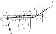
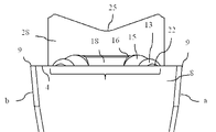
- FIG. 1 It is a schematic perspective view about the cutting insert in the suitable embodiment of this invention. It is a top view about the principal part of the cutting insert of FIG. It is a side view about the principal part of the cutting insert of FIG. It is a front view about the principal part of the cutting insert of FIG. It is a schematic perspective view about the embodiment of the cutting tool which mounted
- FIG. 1-3 shows a preferred embodiment of the present invention, and will be described based on these drawings.
- the cutting insert and the cutting tool according to the present embodiment are particularly suitable for grooving and parting off.
- the cutting insert 1 includes a prismatic chip body 2, a rake face 3 provided on an upper surface of an end portion in the longitudinal direction L of the chip body 2, a rake face 3, and a front face (end face) of the chip body 2. ) And a pair of side cutting edges 5 (5a, 5b) connected to both ends of the front cutting edge 4 and provided on the ridge line between the rake face 3 and the side surface of the chip body. ) And a convex breaker convex portion 6 provided on the rake face 3.
- a front flank 8 is provided on the front X of the end of the chip body 2 provided with the rake face 3. Further, following the pair of side cutting edges 5 (5a, 5b) from the rake face 3, a pair of side relief surfaces 9 (only 9a is visible in FIG. 1) are provided on the side surface of the chip body 2. .
- the cutting insert 1 in FIG. 1 has a point-symmetric shape with respect to the center axis O in the height direction of the chip body 2, and the front cutting edge 4 and the side cutting edge 5 are front (one end face) X. There are two places on the side and the back (the other end face) Y side.
- etc., May be provided only in one edge part.
- a connecting portion 28 is provided on the center side of the rake face 3 on the upper surface of the chip body 2, and on the center side of the connecting portion 28. That is, a V-shaped groove 25 is provided along the longitudinal direction L of the chip body 2 between the rake faces 3 and 3 and the connecting portions 28 and 28 in FIG.
- a V-shaped concave groove 26 on the side opposite to the concave groove 25 of the chip body 2, that is, on the bottom surface of the chip body 2, covers the entire length in the longitudinal direction L of the chip body 2. Is provided.
- the shape on the rake face 3 such as the breaker convex portion 6 is omitted.
- one end in the longitudinal direction L is on the front X side
- the other end in the longitudinal direction L is on the back Y side
- the side X 5 side transverse cutting edge 5a is provided.
- the side where the side cutting edge 5b on the front X side is provided is referred to as the side b side.
- FIG. 2A, FIG. 2B, and FIG. 2C show the front X side of the insert 1.
- the breaker convex portion 6 extends from the back Y side, which is the center side of the chip body 2, from the front cutting edge 4 side. It has two breaker island parts 10 (10a, 10b) which approach the side edge of the rake face 3 toward a certain front X side. That is, the two breaker island portions 10 (10a, 10b) are provided so as to extend toward the side cutting edge 5 toward the front cutting edge 4 side, and the front cutting edge 4 that is the front X side in plan view.
- the letter is in the shape of a Japanese katakana “ha”.
- the two breaker islands 10 (10a, 10b) are both away from the side edge of the rake face 3 from the front X side toward the center side (rear face Y side) of the chip body 2.
- the distance between the two breaker island portions 10 (10a, 10b) is narrower from the front X side toward the center side (back Y side) of the chip body 2.
- the two breaker island portions 10 (10a, 10b) have a height h at the top of the first rising portion 13 (13a, 13b) and the first rising portion 13 from the front X side. 1 comprising gradually lowered from dropping unit 14 (14a, 14b) and, dropper made gradually higher from 14 to a height h 2 greater than the height h 1 of the apex of the first rising portion 13 and the second rising portions 15 (15a, 15b) are provided.
- a transition surface 16 (16a, 16b) for connecting to the center rising portion 18 described later on the back surface Y side of the second rising portion 15.
- the transition surface 16 also has a role of maintaining the strength with which the second rising portion 15 can withstand chip collision.
- the ratio of the difference ⁇ h between the height h 1 to the height h 2 to the height h 1 is 0.4 to 1.8.
- gradually increasing means increasing continuously or stepwise, and includes a case where there is a portion where the height does not change.
- invades from the front X side becomes the concave curved surface shape by the two breaker island parts 10 (10a, 10b) in the width direction which is a direction perpendicular
- the two breaker islands 10 (10a, 10b) are provided so as to approach the side edge of the rake face 3 from the back Y side toward the front X side, chips entering from the front X side are on the back Y side. As it progresses toward, the chip is sandwiched between the two breaker island portions 10 (10a, 10b), and the chips are less likely to jump to the outside between the two breaker island portions 10 (10a, 10b). Proceed along the longitudinal direction L of the chip body 2.
- the breaker island part 10 (10a, 10b) has a first rising part 13, a lowering part 14, and a second rising part 15.
- chips can be curled only by the first rising portion 13 when the feed is under a cutting condition.
- the chips hit the first rising portion 13 and are decelerated, and then the decelerated chips hit the second rising portion 15, so that the chips that are not curled also hit the second rising portion 15. It can be applied and stably curled.
- good chip disposal can be performed under a wide range of cutting conditions ranging from low feed to high feed.
- the breaker groove part 17 and the center rising part 18 are provided between the two breaker island parts 10 (10a, 10b) from the front X side. Further, both side ends of the central rising portion 18 are connected to the two breaker island portions 10 (10a, 10b) to constitute the breaker convex portion 6.
- the chip entering from the front X side by the breaker groove 17 is bent in a more concave curved shape in the width direction.
- the bottom surface portion at the center of the chip contacts the central rising portion 18, and the chip has a role of curving and curling into a mainspring shape.
- the tops of the second rising parts 15 (15a, 15b) of the two breaker island parts 10 (10a, 10b) are provided at a height higher than the central rising part 18.
- the central rising portion 18 is connected to the second rising portion 15 (15a, 15b) and the connecting portion 20 (20a, 20b) located at the end of the transition surface 16 (16a, 16b).
- the rising angle ⁇ 1L of the first rising portion 13 is larger than the rising angle ⁇ 2L of the second rising portion 15.
- a desirable range of the angle ⁇ 1L is 10 ° to 30 °, and more preferably 15 ° to 24 °.
- a desirable range of the angle ⁇ 2L is 5 ° to 25 °, and more preferably 13 ° to 18 °.
- the first rising portion 13 and the second rising portion 15 are convex curved surfaces protruding upward.
- starting-up part 13 is also the convex curved surface which protruded upwards although not shown in figure. Since the first rising portion 13, the lowering portion 14 and the second rising portion 15 having this shape allow chips to pass through in a state where the chips are firmly in contact with the surface of the breaker island portion 10, the chips can be bent reliably.
- the first ridge line R 1 and the second ridge line R 2 are both closer to the side edge of the rake face 3 toward the front side with respect to the longitudinal direction L of the chip body 2, that is, It exists so that the horizontal cutting edge 5 which exists in the vicinity of a pair of horizontal cutting edges 5 may be approached.
- the chips are bent so that the width direction becomes a more concave curved surface shape, and the chips are prevented from passing upward without touching the breaker protrusions 6, and the chips are formed on the surface of the breaker protrusions 6. It will be easier to pass in contact. As a result, the progress speed of the chips can be reduced and the chips can be advanced along the longitudinal direction L. As a result, the chips can be curled more stably. Further, according to the plan view of FIG. 2A, the shift angle ⁇ 2S of the second ridge line R 2 with respect to the longitudinal direction L of the chip body 2 is greater than the shift angle ⁇ 1S of the first ridge line R 1 with respect to the longitudinal direction L of the chip body 2. Is also big.
- a desirable range of the angle ⁇ 1S is 1 ° to 12 °, and more preferably 4 ° to 8 °.
- a desirable range of the angle ⁇ 2S is 8 ° to 30 °, and more preferably 12 ° to 25 °.
- the maximum width w 2 of the second rising portion 15 is larger than the maximum width w 1 of the first rising portion 13.
- the first rising portion 13 is inclined toward the breaker groove 17, even if the chips once hitting the first rising portion 13 flow backward without being curled by the first rising portion 13, the longitudinal direction L Extending along. Then, the chips passing over the first rising portion 13 and passing through the breaker groove 17 side hit the second rising portion 15 also present on the breaker groove 17 side and are curled by the second rising portion 15.
- the preliminary rising portion 22 is provided between the first rising portion 13 and the front cutting edge 4 closer to the front X side than the first rising portion 13. .
- the rising angle ⁇ 0L of the preliminary rising portion 22 is smaller than the rising angle ⁇ 1L of the first rising portion 13.
- the preliminary rising portion 22 functions to smoothly guide chips to the first rising portion 13.
- a desirable range of the angle ⁇ 0L is 5 ° to 15 °, and more preferably 7 ° to 10 °.
- the angle ⁇ 0L indicates the angle of the surface in contact with the first rising portion 13 in the preliminary rising portion 22.
- the front end side of the preliminary rising portion 22 may have an angle larger than the angle ⁇ 0L .
- the preliminary rising portion 22 is not necessarily required, and may have a shape in which the preliminary rising portion 22 does not exist.
- the two breaker island portions 10 (10a, 10b) pass through the center of the front cutting edge 4 with respect to the center line L which is a straight line parallel to the longitudinal direction L.
- the present invention is not limited to this configuration, and in the case of a free cutting insert, the configuration is not line symmetric with respect to the center line O.
- a throw-away cutting tool (hereinafter abbreviated as a cutting tool) 30 in which the cutting insert 1 is mounted on a grooving holder (hereinafter abbreviated as a holder) 32 of this embodiment shown in FIG. And suitable for parting off.
- the cutting tool 30 includes a substantially rod-shaped shank portion 33 and a head portion 34 that is located on one end side of the shank portion 33 and formed integrally with the shank portion 33.
- the head portion 34 includes an insert mounting space 35 on one side a, an upper jaw 37 and a lower jaw 38 that sandwich the insert mounting space 35 from above and below, and a slit 39 connected rearward from the insert mounting space 35.
- the head portion 34 includes an upper jaw connecting portion 41 and a lower jaw connecting portion 42 which are divided by a slit 39, the upper jaw 37 and the upper jaw connecting portion 41 are connected, and the lower jaw 38 and the lower jaw connecting portion 42 are It is connected.
- the upper jaw connecting portion 41 has a through hole 45 for inserting the screw 43
- the lower jaw connecting portion 42 has a screw hole (not shown) into which the screw 43 is screwed.
- An upper clamp surface 48 exists on the lower surface of the upper jaw 37
- a lower clamp surface 49 exists on the upper surface of the lower jaw 38.
- the upper clamp surface 48 of the upper jaw 37 and the lower clamp surface 49 of the lower jaw 38 are inserted into the insert mounting space by inserting the screw 43 from the through hole 45 of the upper jaw connecting portion 41 and screwing it into the screw hole of the lower jaw connecting portion 42.
- the cutting insert 1 attached to 35 is tightened.
- the cutting insert 1 is mounted such that the front cutting edge 4 and the side cutting edge 5 (5a) are located from the front end side of the insert mounting space 35 to the outside.
- the upper clamp surface 48 that comes into contact with the cutting insert 1 of the upper jaw 37 and the lower clamp surface 49 that comes into contact with the cutting insert 1 of the lower jaw 38 are parallel from the front to the rear. 3 has a groove or a convex portion (a convex portion protruding toward the insert mounting space 35 in FIG. 3), and a convex portion or a concave groove (in FIG. V-shaped concave grooves 25 and concave grooves 26) fitted into the convex portions of the clamp surface 48 and the lower clamp surface 49 are provided.
- a region located on the side of the cutting insert 1 of the lower jaw 38 is cut out to be a lower jaw adjacent portion 47 in order to provide a relief to avoid contact with the work material.
Landscapes
- Engineering & Computer Science (AREA)
- Mechanical Engineering (AREA)
- Cutting Tools, Boring Holders, And Turrets (AREA)
- Milling Processes (AREA)
Abstract
Description
前記ブレーカ凸部は、前記正面切刃側に向かうにつれて前記横切刃側に延びる2つのブレーカ島部を有し、該ブレーカ島部は、前記正面切刃側から第1立ち上がり部と、該第1立ち上がり部の頂部から漸次低くなる降下部と、該降下部から前記第1立ち上がり部の頂部よりも高い高さまで漸次高くなる第2立ち上がり部とをそれぞれ有している。
2 チップ本体
3 すくい面
4 正面切刃
5(5a、5b) 横切刃
6 ブレーカ凸部
8 前逃げ面
9(9a) 横逃げ面
10(10a、10b) ブレーカ島部
13(13a、13b) 第1立ち上がり部
14(14a、14b) 降下部
15(15a、15b) 第2立ち上がり部
16(16a、16b) 移行面
17 ブレーカ溝部
18 中央立ち上がり部
20(20a、20b) 連結部
22(22a、22b) 予備立ち上がり部
25、26 凹溝
28 つなぎ部
30 切削工具
32 ホルダ
33 シャンク部
34 ヘッド部
35 インサート取付空間
37 上顎
38 下顎
39 スリット
41 上顎連結部
42 下顎連結部
43 ねじ
45 貫通穴
47 下顎隣接部
48 上クランプ面
49 下クランプ面
X 正面
Y 背面
a 一方の側面
b 他方の側面
R1 第1稜線
R2 第2稜線
θ1L 第1立ち上がり部の立ち上がり角
θ2L 第2立ち上がり部の立ち上がり角
θ1S 第1稜線のチップ本体の長手方向に対するずれ角
θ2S 第2稜線のチップ本体の長手方向に対するずれ角
w1 第1立ち上がり部の最大幅
w2 第2立ち上がり部の最大幅
Claims (11)
- 角柱状のチップ本体と、該チップ本体の長手方向の端部上面に設けられたすくい面と、該すくい面と前記チップ本体の端面との稜線に設けられた正面切刃と、前記すくい面と前記チップ本体の側面との稜線に設けられており、前記正面切刃とそれぞれつながる横切刃と、前記すくい面上に設けられたブレーカ凸部と、を備え、
前記ブレーカ凸部は、前記正面切刃側に向かうにつれて前記横切刃側に延びる2つのブレーカ島部を有し、該ブレーカ島部は、前記正面切刃側から第1立ち上がり部と、該第1立ち上がり部の頂部から漸次低くなる降下部と、該降下部から前記第1立ち上がり部の頂部よりも高い高さまで漸次高くなる第2立ち上がり部とを有する切削インサート。 - 前記2つのブレーカ島部の間には、前記正面切刃側から、ブレーカ溝部と中央立ち上がり部とが設けられており、前記中央立ち上がり部の両側端が、前記2つのブレーカ島部とそれぞれ連結されている請求項1記載の切削インサート。
- 前記2つのブレーカ島部の前記第2立ち上がり面の頂部のほうが、前記中央立ち上がり部の頂部よりも高い請求項2記載の切削インサート。
- 側面視で、前記第1立ち上がり部の立ち上がり角が、前記第2立ち上がり部の立ち上がり角よりも大きい請求項1乃至3のいずれか記載の切削インサート。
- 前記第1立ち上がり部、前記降下部および前記第2立ち上がり部は、上側に突出した凸曲面である請求項1乃至3のいずれか記載の切削インサート。
- 平面視で、前記第1立ち上がり部の凸曲面の頂部をつないだ線を第1稜線とし、前記第2立ち上がり部の凸曲面の頂部をつないだ線を第2稜線としたとき、前記第1稜線および前記第2稜線は、前記チップ本体の長手方向に対して、いずれも前記端面側に向かうにつれて前記すくい面の側端に近づくように設けられている請求項5記載の切削インサート。
- 前記第2稜線の前記チップ本体の長手方向に対するずれ角が、前記第1稜線の前記チップ本体の長手方向に対するずれ角よりも大きい請求項6記載の切削インサート。
- 平面視で、前記第1立ち上がり部の最大幅よりも前記第2立ち上がり部の最大幅が大きい請求項1乃至7のいずれか記載の切削インサート。
- 前記第1立ち上がり部よりも前記正面切刃側に予備立ち上がり部が設けられ、該予備立ち上がり部の立ち上がり角は前記第1立ち上がり部の立ち上がり角よりも小さい請求項1乃至8のいずれか記載の切削インサート。
- 前記2つのブレーカ島部は、前記正面切刃の中央を通る前記チップ本体の長手方向に平行な中央線に対して線対称である請求項1乃至9のいずれか記載の切削インサート。
- 請求項1乃至10のいずれか記載の切削インサートと、インサート取付空間を有するホルダとを有し、前記切削インサートの前記正面切刃が前記ホルダの外部に位置するように前記切削インサートが前記ホルダのインサート取付空間に装着されている切削工具。
Priority Applications (4)
| Application Number | Priority Date | Filing Date | Title |
|---|---|---|---|
| EP13842418.9A EP2902140B1 (en) | 2012-09-27 | 2013-09-27 | Cutting insert and cutting tool |
| US14/422,181 US9925595B2 (en) | 2012-09-27 | 2013-09-27 | Cutting insert and cutting tool |
| CN201380036744.2A CN104428086B (zh) | 2012-09-27 | 2013-09-27 | 切削镶刀以及切削工具 |
| JP2014538645A JP5869687B2 (ja) | 2012-09-27 | 2013-09-27 | 切削インサートおよび切削工具 |
Applications Claiming Priority (2)
| Application Number | Priority Date | Filing Date | Title |
|---|---|---|---|
| JP2012-214486 | 2012-09-27 | ||
| JP2012214486 | 2012-09-27 |
Publications (1)
| Publication Number | Publication Date |
|---|---|
| WO2014051086A1 true WO2014051086A1 (ja) | 2014-04-03 |
Family
ID=50388479
Family Applications (1)
| Application Number | Title | Priority Date | Filing Date |
|---|---|---|---|
| PCT/JP2013/076357 Ceased WO2014051086A1 (ja) | 2012-09-27 | 2013-09-27 | 切削インサートおよび切削工具 |
Country Status (5)
| Country | Link |
|---|---|
| US (1) | US9925595B2 (ja) |
| EP (1) | EP2902140B1 (ja) |
| JP (1) | JP5869687B2 (ja) |
| CN (1) | CN104428086B (ja) |
| WO (1) | WO2014051086A1 (ja) |
Cited By (3)
| Publication number | Priority date | Publication date | Assignee | Title |
|---|---|---|---|---|
| RU2765010C1 (ru) * | 2018-12-04 | 2022-01-24 | Хартметалль-Веркцойгфабрик Пауль Хорн Гмбх | Режущая пластина и инструмент для обработки заготовки резанием |
| RU2765010C9 (ru) * | 2018-12-04 | 2022-07-18 | Хартметалль-Веркцойгфабрик Пауль Хорн Гмбх | Режущая пластина и инструмент для обработки заготовки резанием |
| WO2025094666A1 (ja) * | 2023-10-30 | 2025-05-08 | 京セラ株式会社 | 切削インサート、切削工具、及び切削加工物の製造方法 |
Families Citing this family (19)
| Publication number | Priority date | Publication date | Assignee | Title |
|---|---|---|---|---|
| JP6038594B2 (ja) * | 2012-10-26 | 2016-12-07 | 住友電工ハードメタル株式会社 | 突っ切り加工用工具 |
| CN106132601B (zh) * | 2014-03-25 | 2018-12-11 | 京瓷株式会社 | 切削镶刀、切削工具以及切削加工物的制造方法 |
| CN108025373B (zh) * | 2015-09-07 | 2019-10-01 | 京瓷株式会社 | 切削刀片、切削工具以及切削加工物的制造方法 |
| CN106270580B (zh) * | 2016-08-10 | 2020-04-07 | 台州市锐安硬质合金工具有限公司 | 一种径向切槽、切断和轴向车削的多功能刀片 |
| EP3338931B1 (en) * | 2016-09-27 | 2024-05-29 | Tungaloy Corporation | Cutting insert and cutting tool |
| US10926337B2 (en) * | 2016-11-07 | 2021-02-23 | Sumitomo Electric Hardmetal Corp. | Cutting-off processing tool |
| US10384268B1 (en) * | 2018-02-05 | 2019-08-20 | Iscar, Ltd. | Grooving insert having rearwardly pointing arrowhead-shaped chip former |
| DE112019003446T5 (de) * | 2018-07-06 | 2021-03-18 | Kyocera Corporation | Schneideinsatz, schneidwerkzeug und verfahren zur herstellung eines maschinell bearbeiteten produkts |
| JP6936975B2 (ja) * | 2018-12-28 | 2021-09-22 | 株式会社タンガロイ | 切削インサート及び切削工具 |
| US10857603B2 (en) | 2019-03-19 | 2020-12-08 | Iscar, Ltd. | Insert holder having transversely oriented insert receiving pocket with upper stopper surface, cutting tool and cutting insert |
| US11980945B2 (en) * | 2019-03-29 | 2024-05-14 | Kyocera Corporation | Cutting insert, cutting tool, and method for manufacturing machined product |
| CN110000400B (zh) * | 2019-04-03 | 2024-07-12 | 株洲欧科亿数控精密刀具股份有限公司 | 一种双面槽型切削刀片 |
| CN111001835A (zh) * | 2019-12-25 | 2020-04-14 | 厦门金鹭特种合金有限公司 | 一种带断屑槽的超硬切槽刀具 |
| CN111468748B (zh) * | 2020-04-28 | 2025-02-11 | 厦门金鹭特种合金有限公司 | 一种可转位切削刀片 |
| CN111730079B (zh) * | 2020-07-21 | 2025-04-01 | 北京沃尔德金刚石工具股份有限公司 | 一种新型断屑台槽刀 |
| JP6976522B1 (ja) * | 2021-02-18 | 2021-12-08 | 株式会社タンガロイ | 切削工具及び切削インサート |
| US11806793B2 (en) | 2021-11-03 | 2023-11-07 | Iscar, Ltd. | Cutting insert having laterally spaced apart, longitudinally extending wedge abutment surfaces, tool holder and cutting tool |
| US12275078B2 (en) | 2022-05-03 | 2025-04-15 | Iscar, Ltd. | Rotationally asymmetric double-ended grooving cutting insert, insert holder and cutting tool |
| US12465981B2 (en) * | 2022-09-07 | 2025-11-11 | Iscar, Ltd. | Cemented carbide cutting insert for parting metal workpieces |
Citations (5)
| Publication number | Priority date | Publication date | Assignee | Title |
|---|---|---|---|---|
| JPH02284805A (ja) * | 1989-02-10 | 1990-11-22 | Iscar Ltd | 切削インサート |
| JPH0839305A (ja) * | 1994-07-28 | 1996-02-13 | Kyocera Corp | 切削インサート |
| JPH0871807A (ja) * | 1994-08-31 | 1996-03-19 | Kyocera Corp | 切削インサート |
| JP2005288613A (ja) | 2004-03-31 | 2005-10-20 | Mitsubishi Materials Corp | スローアウェイチップ |
| JP2006502874A (ja) * | 2002-10-18 | 2006-01-26 | マンチェスター トゥール カンパニー | 工具ホルダ及び切り屑破砕表面を有する金属切削差込工具 |
Family Cites Families (13)
| Publication number | Priority date | Publication date | Assignee | Title |
|---|---|---|---|---|
| CN1013746B (zh) * | 1988-09-29 | 1991-09-04 | 伊斯卡控股股份公司 | 金属切削镶块 |
| JP3250939B2 (ja) | 1995-04-26 | 2002-01-28 | 京セラ株式会社 | 切削インサート |
| JP4445915B2 (ja) * | 2004-10-29 | 2010-04-07 | 住友電工ハードメタル株式会社 | 溝入れ工具用焼結体 |
| JP4849815B2 (ja) | 2005-03-29 | 2012-01-11 | 京セラ株式会社 | 切削インサートおよび溝入れ加工用切削工具 |
| CN101663116B (zh) * | 2007-04-20 | 2011-12-07 | 三菱麻铁里亚尔株式会社 | 切削刀片及切削方法 |
| JP5056215B2 (ja) * | 2007-07-04 | 2012-10-24 | 三菱マテリアル株式会社 | 切削インサート |
| JP5515504B2 (ja) * | 2008-08-22 | 2014-06-11 | 三菱マテリアル株式会社 | 切削インサート |
| EP2359966B1 (en) * | 2008-11-21 | 2017-06-14 | Kyocera Corporation | Cutting insert, cutting tool, and cutting method using cutting tool |
| EP2495058B1 (en) * | 2009-10-29 | 2018-05-16 | Kyocera Corporation | Cutting insert |
| JP5552162B2 (ja) * | 2010-05-27 | 2014-07-16 | 京セラ株式会社 | 切削インサートおよび切削工具、ならびにそれらを用いた切削加工物の製造方法 |
| CN201988740U (zh) | 2010-12-07 | 2011-09-28 | 中硬金属切削(大连)有限公司 | 一种用于低碳钢管件粗加工的立装机夹五刃切断刀片 |
| KR101520798B1 (ko) | 2011-02-28 | 2015-05-15 | 쿄세라 코포레이션 | 절삭 인서트, 절삭 공구, 및 그것들을 사용한 절삭 가공물의 제조 방법 |
| US8939684B2 (en) * | 2012-05-15 | 2015-01-27 | Iscar, Ltd. | Cutting insert with chip-control arrangement having recess depths and projection heights which increase with distance from cutting edge |
-
2013
- 2013-09-27 WO PCT/JP2013/076357 patent/WO2014051086A1/ja not_active Ceased
- 2013-09-27 EP EP13842418.9A patent/EP2902140B1/en active Active
- 2013-09-27 JP JP2014538645A patent/JP5869687B2/ja active Active
- 2013-09-27 US US14/422,181 patent/US9925595B2/en not_active Expired - Fee Related
- 2013-09-27 CN CN201380036744.2A patent/CN104428086B/zh active Active
Patent Citations (5)
| Publication number | Priority date | Publication date | Assignee | Title |
|---|---|---|---|---|
| JPH02284805A (ja) * | 1989-02-10 | 1990-11-22 | Iscar Ltd | 切削インサート |
| JPH0839305A (ja) * | 1994-07-28 | 1996-02-13 | Kyocera Corp | 切削インサート |
| JPH0871807A (ja) * | 1994-08-31 | 1996-03-19 | Kyocera Corp | 切削インサート |
| JP2006502874A (ja) * | 2002-10-18 | 2006-01-26 | マンチェスター トゥール カンパニー | 工具ホルダ及び切り屑破砕表面を有する金属切削差込工具 |
| JP2005288613A (ja) | 2004-03-31 | 2005-10-20 | Mitsubishi Materials Corp | スローアウェイチップ |
Non-Patent Citations (1)
| Title |
|---|
| See also references of EP2902140A4 * |
Cited By (3)
| Publication number | Priority date | Publication date | Assignee | Title |
|---|---|---|---|---|
| RU2765010C1 (ru) * | 2018-12-04 | 2022-01-24 | Хартметалль-Веркцойгфабрик Пауль Хорн Гмбх | Режущая пластина и инструмент для обработки заготовки резанием |
| RU2765010C9 (ru) * | 2018-12-04 | 2022-07-18 | Хартметалль-Веркцойгфабрик Пауль Хорн Гмбх | Режущая пластина и инструмент для обработки заготовки резанием |
| WO2025094666A1 (ja) * | 2023-10-30 | 2025-05-08 | 京セラ株式会社 | 切削インサート、切削工具、及び切削加工物の製造方法 |
Also Published As
| Publication number | Publication date |
|---|---|
| EP2902140A4 (en) | 2016-05-11 |
| CN104428086A (zh) | 2015-03-18 |
| JP5869687B2 (ja) | 2016-02-24 |
| EP2902140B1 (en) | 2021-07-28 |
| US20150224581A1 (en) | 2015-08-13 |
| JPWO2014051086A1 (ja) | 2016-08-25 |
| CN104428086B (zh) | 2017-06-30 |
| US9925595B2 (en) | 2018-03-27 |
| EP2902140A1 (en) | 2015-08-05 |
Similar Documents
| Publication | Publication Date | Title |
|---|---|---|
| JP5869687B2 (ja) | 切削インサートおよび切削工具 | |
| EP2849906B1 (en) | Cutting insert with chip-control arrangement | |
| EP2160261B1 (en) | Cutting insert with protrusions formed at corner area thereof | |
| JP2744574B2 (ja) | 旋削並びに溝切り用の多角形インサート | |
| EP2838682B1 (en) | Cutting insert chip-control arrangement | |
| JP5517700B2 (ja) | 切削インサートおよび切削工具並びにそれを用いた切削方法 | |
| CA2766773A1 (en) | Cutting insert | |
| CN101626860A (zh) | 螺纹切削用刀片 | |
| WO2009025918A2 (en) | Round cutting insert with chip control feature | |
| WO2014065046A1 (ja) | 突っ切り加工用工具 | |
| US6146064A (en) | Cutting insert with improved chip control | |
| JP2005288613A (ja) | スローアウェイチップ | |
| JP2007301669A (ja) | スローアウェイチップ | |
| JP4849815B2 (ja) | 切削インサートおよび溝入れ加工用切削工具 | |
| JP2008213077A (ja) | 切削インサート及びインサート着脱式切削工具 | |
| JP5831549B2 (ja) | 切削インサート | |
| JP5109485B2 (ja) | 旋削用スローアウェイチップ | |
| JP2007260841A (ja) | 切削インサート | |
| JP2009233799A (ja) | 切削インサート及び切削工具、並びに切削方法 | |
| JP2021186945A (ja) | 切削インサート |
Legal Events
| Date | Code | Title | Description |
|---|---|---|---|
| 121 | Ep: the epo has been informed by wipo that ep was designated in this application |
Ref document number: 13842418 Country of ref document: EP Kind code of ref document: A1 |
|
| WWE | Wipo information: entry into national phase |
Ref document number: 2013842418 Country of ref document: EP |
|
| ENP | Entry into the national phase |
Ref document number: 2014538645 Country of ref document: JP Kind code of ref document: A |
|
| WWE | Wipo information: entry into national phase |
Ref document number: 14422181 Country of ref document: US |
|
| NENP | Non-entry into the national phase |
Ref country code: DE |