WO2014054782A1 - 充電コネクタ - Google Patents
充電コネクタ Download PDFInfo
- Publication number
- WO2014054782A1 WO2014054782A1 PCT/JP2013/077090 JP2013077090W WO2014054782A1 WO 2014054782 A1 WO2014054782 A1 WO 2014054782A1 JP 2013077090 W JP2013077090 W JP 2013077090W WO 2014054782 A1 WO2014054782 A1 WO 2014054782A1
- Authority
- WO
- WIPO (PCT)
- Prior art keywords
- connector
- housing
- case
- connector housing
- temporary
- Prior art date
- Legal status (The legal status is an assumption and is not a legal conclusion. Google has not performed a legal analysis and makes no representation as to the accuracy of the status listed.)
- Ceased
Links
Images


Classifications
-
- H—ELECTRICITY
- H01—ELECTRIC ELEMENTS
- H01R—ELECTRICALLY-CONDUCTIVE CONNECTIONS; STRUCTURAL ASSOCIATIONS OF A PLURALITY OF MUTUALLY-INSULATED ELECTRICAL CONNECTING ELEMENTS; COUPLING DEVICES; CURRENT COLLECTORS
- H01R13/00—Details of coupling devices of the kinds covered by groups H01R12/70 or H01R24/00 - H01R33/00
- H01R13/46—Bases; Cases
- H01R13/502—Bases; Cases composed of different pieces
- H01R13/506—Bases; Cases composed of different pieces assembled by snap action of the parts
-
- B—PERFORMING OPERATIONS; TRANSPORTING
- B60—VEHICLES IN GENERAL
- B60L—PROPULSION OF ELECTRICALLY-PROPELLED VEHICLES; SUPPLYING ELECTRIC POWER FOR AUXILIARY EQUIPMENT OF ELECTRICALLY-PROPELLED VEHICLES; ELECTRODYNAMIC BRAKE SYSTEMS FOR VEHICLES IN GENERAL; MAGNETIC SUSPENSION OR LEVITATION FOR VEHICLES; MONITORING OPERATING VARIABLES OF ELECTRICALLY-PROPELLED VEHICLES; ELECTRIC SAFETY DEVICES FOR ELECTRICALLY-PROPELLED VEHICLES
- B60L53/00—Methods of charging batteries, specially adapted for electric vehicles; Charging stations or on-board charging equipment therefor; Exchange of energy storage elements in electric vehicles
- B60L53/10—Methods of charging batteries, specially adapted for electric vehicles; Charging stations or on-board charging equipment therefor; Exchange of energy storage elements in electric vehicles characterised by the energy transfer between the charging station and the vehicle
- B60L53/14—Conductive energy transfer
- B60L53/16—Connectors, e.g. plugs or sockets, specially adapted for charging electric vehicles
-
- H—ELECTRICITY
- H01—ELECTRIC ELEMENTS
- H01R—ELECTRICALLY-CONDUCTIVE CONNECTIONS; STRUCTURAL ASSOCIATIONS OF A PLURALITY OF MUTUALLY-INSULATED ELECTRICAL CONNECTING ELEMENTS; COUPLING DEVICES; CURRENT COLLECTORS
- H01R13/00—Details of coupling devices of the kinds covered by groups H01R12/70 or H01R24/00 - H01R33/00
- H01R13/46—Bases; Cases
- H01R13/516—Means for holding or embracing insulating body, e.g. casing, hoods
-
- H—ELECTRICITY
- H01—ELECTRIC ELEMENTS
- H01R—ELECTRICALLY-CONDUCTIVE CONNECTIONS; STRUCTURAL ASSOCIATIONS OF A PLURALITY OF MUTUALLY-INSULATED ELECTRICAL CONNECTING ELEMENTS; COUPLING DEVICES; CURRENT COLLECTORS
- H01R43/00—Apparatus or processes specially adapted for manufacturing, assembling, maintaining, or repairing of line connectors or current collectors or for joining electric conductors
- H01R43/20—Apparatus or processes specially adapted for manufacturing, assembling, maintaining, or repairing of line connectors or current collectors or for joining electric conductors for assembling or disassembling contact members with insulating base, case or sleeve
-
- H—ELECTRICITY
- H01—ELECTRIC ELEMENTS
- H01R—ELECTRICALLY-CONDUCTIVE CONNECTIONS; STRUCTURAL ASSOCIATIONS OF A PLURALITY OF MUTUALLY-INSULATED ELECTRICAL CONNECTING ELEMENTS; COUPLING DEVICES; CURRENT COLLECTORS
- H01R13/00—Details of coupling devices of the kinds covered by groups H01R12/70 or H01R24/00 - H01R33/00
- H01R13/62—Means for facilitating engagement or disengagement of coupling parts or for holding them in engagement
- H01R13/639—Additional means for holding or locking coupling parts together, after engagement, e.g. separate keylock, retainer strap
-
- Y—GENERAL TAGGING OF NEW TECHNOLOGICAL DEVELOPMENTS; GENERAL TAGGING OF CROSS-SECTIONAL TECHNOLOGIES SPANNING OVER SEVERAL SECTIONS OF THE IPC; TECHNICAL SUBJECTS COVERED BY FORMER USPC CROSS-REFERENCE ART COLLECTIONS [XRACs] AND DIGESTS
- Y02—TECHNOLOGIES OR APPLICATIONS FOR MITIGATION OR ADAPTATION AGAINST CLIMATE CHANGE
- Y02T—CLIMATE CHANGE MITIGATION TECHNOLOGIES RELATED TO TRANSPORTATION
- Y02T10/00—Road transport of goods or passengers
- Y02T10/60—Other road transportation technologies with climate change mitigation effect
- Y02T10/70—Energy storage systems for electromobility, e.g. batteries
-
- Y—GENERAL TAGGING OF NEW TECHNOLOGICAL DEVELOPMENTS; GENERAL TAGGING OF CROSS-SECTIONAL TECHNOLOGIES SPANNING OVER SEVERAL SECTIONS OF THE IPC; TECHNICAL SUBJECTS COVERED BY FORMER USPC CROSS-REFERENCE ART COLLECTIONS [XRACs] AND DIGESTS
- Y02—TECHNOLOGIES OR APPLICATIONS FOR MITIGATION OR ADAPTATION AGAINST CLIMATE CHANGE
- Y02T—CLIMATE CHANGE MITIGATION TECHNOLOGIES RELATED TO TRANSPORTATION
- Y02T10/00—Road transport of goods or passengers
- Y02T10/60—Other road transportation technologies with climate change mitigation effect
- Y02T10/7072—Electromobility specific charging systems or methods for batteries, ultracapacitors, supercapacitors or double-layer capacitors
-
- Y—GENERAL TAGGING OF NEW TECHNOLOGICAL DEVELOPMENTS; GENERAL TAGGING OF CROSS-SECTIONAL TECHNOLOGIES SPANNING OVER SEVERAL SECTIONS OF THE IPC; TECHNICAL SUBJECTS COVERED BY FORMER USPC CROSS-REFERENCE ART COLLECTIONS [XRACs] AND DIGESTS
- Y02—TECHNOLOGIES OR APPLICATIONS FOR MITIGATION OR ADAPTATION AGAINST CLIMATE CHANGE
- Y02T—CLIMATE CHANGE MITIGATION TECHNOLOGIES RELATED TO TRANSPORTATION
- Y02T90/00—Enabling technologies or technologies with a potential or indirect contribution to GHG emissions mitigation
- Y02T90/10—Technologies relating to charging of electric vehicles
- Y02T90/14—Plug-in electric vehicles
Definitions
- the present invention relates to a charging connector used when charging a battery mounted on a vehicle such as an electric vehicle or a hybrid electric vehicle.
- a charging connector has been used to charge a battery mounted on a vehicle such as an electric vehicle (EV) or a hybrid electric vehicle (HEV) (see, for example, Patent Document 1).
- EV electric vehicle
- HEV hybrid electric vehicle
- An example of the charging connector will be described with reference to FIG.
- the charging connector 100 includes a connector case 110 formed by assembling a pair of case division bodies 110 ⁇ / b> A and 110 ⁇ / b> B, and a charging terminal (not connected) accommodated in the connector case 110 and connected to the electric wire W.
- a connector main body 120 having a connector housing 121 accommodated in the connector housing 121, and a locking mechanism 130 capable of preventing the mating connector (not shown) and the connector main body 120 from being detached from each other.
- the connector case 110 includes a housing accommodating portion 111 that accommodates the connector housing 121 of the connector main body 120, an electric wire accommodating portion 112 that accommodates an electric wire W connected to a charging terminal (not shown) of the connector main body 120, and a housing accommodating portion 111. And a lock housing portion 113 for housing the lock mechanism 130 above the wire housing portion 112.
- a positioning recess 114 is formed in the housing accommodating portion 111.
- the positioning recess 114 has an axial restriction groove 114A formed between the two axial restriction ribs 115A and 115B positioned at the opening at the tip of the housing accommodating portion 111, and a rotational direction restriction formed on the axial restriction rib 115A. It is comprised by the hole 114B.
- a part of the electric wire housing portion 112 is a handle that is gripped by an operator. And the electric wire W connected to the charging terminal (not shown) of the connector main body 120 is pulled out outside so that the electric wire accommodating part 112 may be passed from the housing accommodating part 111.
- FIG. 1 A part of the electric wire housing portion 112 is a handle that is gripped by an operator. And the electric wire W connected to the charging terminal (not shown) of the connector main body 120 is pulled out outside so that the electric wire accommodating part 112 may be passed from the housing accommodating part 111.
- the connector main body 120 includes a plurality of charging terminals (not shown) connected to a mating terminal (not shown) of the mating connector and a plurality of terminal accommodating housing portions 121A that respectively accommodate the plurality of charging terminals inside the circumferential direction. And a connector housing 121 arranged at intervals.
- the connector housing 121 is formed with a positioning convex portion 122 that engages with the positioning concave portion 114.
- the positioning convex part 122 is provided between the two fitting ribs 122A and 122B and the two fitting ribs 122A and 122B disposed in front of the axial restriction rib 115A and in the axial restriction groove 114A, respectively. It is comprised by the rotation direction control protrusion 123 engaged with the control hole 114B.
- the connector main body 120 is inserted into one case divided body 110A until the positioning convex portion 122 engages with the positioning concave portion 114 of one case divided body 110A, and the connector housing 121 is a temporary storage position. Thereby, the axial movement and rotation in the rotational direction of the connector housing 121 in one case division body 110A are restricted.
- the edge of the other case division body 110B is attached to the edge of the one case division body 110A.
- the charging connector 100 can be assembled.
- the connector housing 121 is lifted from the one case divided body 110A by an external force such as the tension of the electric wire W when the connector housing 121 is temporarily accommodated with respect to the one case divided body 110A.
- the engagement between the rotation direction restricting hole 114B and the rotation direction restricting protrusion 123 may be released. Therefore, the worker has to assemble the charging connector 100 while holding the connector housing 121 in the temporary housing position with respect to the one case divided body 110A, and the assembling workability of the charging connector 100 is complicated.
- the present invention has been made to solve the above-described problems, and it is an object of the present invention to provide a charging connector that can securely hold a connector housing in a temporary housing position with respect to one case divided body and improve assembly workability. To do.
- a connector case formed by assembling a plurality of case division bodies, and one or more charging terminals accommodated in the connector case and connected to an electric wire are provided in the connector housing.
- a connector body, and one of the plurality of case division bodies and the connector housing is provided with a positioning portion, and the other of the plurality of case division bodies and the connector housing includes: A positioned portion that engages with the positioning portion is provided, and the connector main body is inserted into one case division body until the positioning portion engages with the positioned portion, and the connector housing is temporarily accommodated.
- the remaining case division body is assembled to the one case division body that temporarily accommodates the connector housing, and the one case division body is assembled.
- a temporary holding portion for holding at a temporary housing position of the connector housing is provided in one of the case divided body and the connector housing, and the other of the one case divided body and the connector housing is A charging connector is provided, wherein a temporarily held portion that is locked to the temporary holding portion is provided.
- the temporary holding portion has a base end fixed to the one case division body and a free end, and the temporary holding portion is the one case division.
- the connector housing is allowed to be inserted into the body in the temporary housing position, and the temporary holding portion is locked to the temporary held portion at the temporary housing position of the connector housing.
- the number of the charging terminals is two or more
- the connector housing accommodates the two or more charging terminals therein, and the circumferential direction of the connector housing
- Two or more cylindrical terminal accommodating housing portions arranged at intervals, and the temporary holding portion is constituted by a step formed on the outer peripheral surface of one terminal accommodating housing portion.
- the temporary holding portion is locked to the temporary held portion, so that the operator can connect the connector housing to one case divided body. Can be held in the temporary storage position, and the assembling workability of the charging connector is improved.
- FIG. 1 is an exploded perspective view of a conventional charging connector (both side exploded view of a case body).
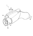
- FIG. 2 is a perspective view showing the charging connector according to the present embodiment.
- FIG. 3 is an exploded perspective view (one-side exploded view of the case body) showing the charging connector according to the present embodiment.
- FIG. 4 is an exploded perspective view (both side exploded view of the case body) showing the charging connector according to the present embodiment.
- FIG. 5 is a cross-sectional view showing the inside of the charging connector according to the present embodiment.
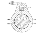
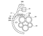
- 6A is a cross-sectional view taken along the line AA in FIG. 6B is a cross-sectional view taken along the line BB in FIG.
- FIG. 7A is a cross-sectional view showing the assembly process of the charging connector according to the present embodiment.
- FIG. 7B is a cross-sectional view showing the assembly process of the charging connector according to the present embodiment.
- FIG. 2 is a perspective view of the charging connector according to the present embodiment.
- 3 and 4 are exploded perspective views of the charging connector according to the present embodiment.
- FIG. 5 is a cross-sectional view showing the inside of the charging connector 1 according to the present embodiment.
- 6A is a cross-sectional view taken along the line AA in FIG. 6B is a cross-sectional view taken along the line BB in FIG.
- the charging connector 1 is configured to be able to fit into a mating connector (charging inlet device) provided with a mating terminal.
- the charging connector 1 includes a connector case 10 formed by assembling a pair of case divided bodies 10A and 10B, and a plurality of charging terminals (not shown) accommodated in the connector case 10 and connected to the electric wires W.
- a connector main body 20 accommodated in the housing 21 and a lock mechanism 30 capable of preventing mutual detachment when the mating connector (not shown) and the connector main body 20 are fitted to each other are provided.
- the connector case 10 includes a housing accommodating portion 11 that accommodates a connector housing 21, an electric wire accommodating portion 12 that accommodates an electric wire W connected to a charging terminal (not shown), and a housing accommodating. It has the lock accommodating part 13 which accommodates the lock mechanism 30 above the part 11 and the electric wire accommodating part 12.
- a positioning recess 14 is formed in the housing accommodating portion 11 as a positioned portion.
- the positioning recess 14 has an axial restriction groove 14A formed between two axial restriction ribs 15A and 15B located at the opening at the tip of the housing accommodating portion 11, and a rotation formed in one axial restriction rib 15A. It is comprised by the direction control hole 14B.
- the housing holding portion 11 of one case division body 10A is provided with a temporary holding portion 16 that holds the connector housing 21 at the temporary holding position.
- the temporary housing position of the connector housing 21 is a position where the connector housing 21 is inserted into the case divided body 10A and a rotation direction restricting projection 23C and a rotation direction restricting hole 14B described later of the connector housing 21 are temporarily engaged. Is shown.
- the temporary holding portion 16 is provided at the distal end of the elastic arm portion 17 and the elastic arm portion 17 whose base end is fixed to the inner surface of the case divided body 10A and the distal end is a free end. And a claw portion 18 projecting toward the connector housing 21 side.
- the elastic arm portion 17 allows insertion of the connector housing 21 into the temporary housing position with respect to the case divided body 10A by bending deformation.
- the claw portion 18 includes an inclined surface 18A and a locking surface 18B that is locked to a temporary holding portion 26 (described later) of the connector housing 21 (see FIGS. 6B and 7A, 7B).
- An electric wire housing portion 12 is provided on the rear side of the housing housing portion 11. A part of the electric wire housing portion 12 is a handle that is held by an operator. And the electric wire W connected to the charging terminal (not shown) of the connector main body 20 is pulled out outside so that the electric wire accommodating part 12 may be passed from the housing accommodating part 11.
- FIG. 1 A part of the electric wire housing portion 12 is a handle that is held by an operator. And the electric wire W connected to the charging terminal (not shown) of the connector main body 20 is pulled out outside so that the electric wire accommodating part 12 may be passed from the housing accommodating part 11.
- the connector main body 20 includes a plurality of charging terminals (not shown) connected to a mating terminal (not shown) of the mating connector and a cylindrical connector housing 21 that houses the plurality of charging terminals. I have.
- the connector housing 21 includes an external hood 22 that is provided outside the connector case 10 and engages with a mating connector (not shown), and the inside of the connector case 10 from within the external hood 22. And a plurality of terminal accommodating housing portions 24 provided over.
- a positioning convex portion 23 as a positioning portion that engages with the positioning concave portion 14 is formed.
- the positioning convex portion 23 is provided between the two fitting ribs 23A and 23B and the two fitting ribs 23A and 23B disposed in front of the axial restriction rib 15A and in the axial restriction groove 14A, respectively. It is comprised by the rotation direction control protrusion 23C engaged with the control hole 14B.
- the plurality of terminal accommodating housing portions 24 accommodate a plurality of charging terminals (not shown), respectively, and are arranged at intervals in the circumferential direction of the connector housing 21.
- One terminal accommodating housing portion 24 is formed in a cylindrical shape, and an outer peripheral surface 24A having an arc shape is provided on the outer periphery.
- the outer peripheral surface 24A is provided with a temporarily held portion 26 to which the claw portion 18 (locking surface 18B) of the temporary holding portion 16 is locked.
- the temporarily held portion 26 is configured by a step formed continuously from the apex of the arc-shaped outer peripheral surface 24A.
- the locking mechanism 30 prevents the mating connector and the connector housing 21 from being detached when the mating connector (not shown) and the connector housing 21 are fitted.
- the lock mechanism 30 is provided at a lock arm 31, a lock claw 32 that is provided at the tip of the lock arm 31 and engages with a mating connector (not shown), and a rear end of the lock arm 31.
- a lock operation unit 33 that allows the operator to operate the lock arm 31 and a coil spring 34 that urges the lock arm 31 toward the lock position (solid line in FIG. 5) are provided.
- the lock arm 31 has a lock position (solid line in FIG. 5) where the lock claw 32 engages with a counterpart connector (not shown), and a release position (FIG. 5) where the engagement between the counterpart connector and the lock claw 32 is released. And a swing fulcrum 31A.
- the lock claw 32 and the lock operation part 33 are exposed to the outside of the connector case 10, and the lock operation part 33 can be operated to turn on / off the micro switch M (see FIG. 5).
- FIG. 7A and 7B are cross-sectional views showing the assembly process of the charging connector 1 according to this embodiment.
- the connector main body 20 and the lock mechanism 30 are inserted into one case division body 10A. That is, the connector housing 21 is accommodated in the housing accommodating portion 11 of the one case divided body 10A while the one fitting rib 23B is inserted into the axial restriction groove 14A of the one case divided body 10A, and the electric wire accommodating portion 12 is accommodated. And the lock mechanism 30 is housed in the lock housing portion 13 (the state shown in FIGS. 3 and 5).
- the claw portion 18 (inclined surface 18A) of the temporary holding portion 16 contacts the outer peripheral surface 24A of the terminal housing housing portion 24, and the elastic arm portion 17 of the temporary holding portion 16 is elastically deformed.
- the connector main body 20 is inserted into one case divided body 10A until the position where the rotation direction restricting protrusion 23C engages with the rotation direction restricting hole 14B of one case divided body 10A, the connector housing 21 is inserted.
- the elastic arm portion 17 is restored and the claw portion 18 of the temporary holding portion 16 is locked to the temporary held portion 26.
- the positioning convex portion 23 engages with the positioning concave portion 14 of one case divided body 10A.
- the rotation of the connector housing 21 in one case division body 10A is restricted by the rotation direction restriction projection 23C engaging with the rotation direction restriction hole 14B.
- the movement of the connector housing 21 in the axial direction with respect to one case division body 10A is also restricted by inserting one fitting rib 23B into the axial direction restriction groove 14A.
- the charging connector 1 can be assembled.
- the temporary holding portion 16 (the claw portion 18) is locked to the temporary held portion 26 at the temporary housing position of the connector housing 21 with respect to one case divided body 10A.
- the engagement between the rotation direction restriction hole 14B and the rotation direction restriction projection 23C is released without the connector housing 21 floating from one case division body 10A due to an external force such as tension of the electric wire W. Can be prevented. Therefore, the connector housing 21 can be securely held in the temporary housing position with respect to the one case divided body 10A, and there is no need for the operator to assemble the charging connector 1 while holding the connector housing 21 in the temporary housing position. Assembling workability is improved.
- the temporary holding portion 16 and the temporary held portion 26 are locked to each other when the connector housing 21 is inserted into the temporary housing position with respect to the one case divided body 10A. That is, the temporary holding part 16 can be locked to the temporary held part 26 only by inserting the connector housing 21 into one case division body 10A.
- the temporarily held portion 26 is configured by a step formed continuously from the arc-shaped outer peripheral surface 24A. Thereby, the provisionally held portion 26 can be easily formed using the outer peripheral surface 24 ⁇ / b> A of the terminal accommodating housing portion 24.
- the embodiment of the present invention can be modified as follows. Specifically, the concave / convex relationship between the positioning concave portion 114 and the positioning convex portion 122 may be reversed, and similarly, the relationship between the temporary holding portion 16 and the temporary held portion 26 may be reversed.
Landscapes
- Engineering & Computer Science (AREA)
- Manufacturing & Machinery (AREA)
- Power Engineering (AREA)
- Transportation (AREA)
- Mechanical Engineering (AREA)
- Details Of Connecting Devices For Male And Female Coupling (AREA)
- Connector Housings Or Holding Contact Members (AREA)
Description
本発明は、電気自動車やハイブリッド電気自動車等の車両に搭載されるバッテリーを充電する際に用いられる充電コネクタに関する。
従来から、電気自動車(EV)やハイブリッド電気自動車(HEV)等の車両に搭載されたバッテリーを充電するために、充電コネクタが用いられている(例えば、特許文献1参照)。充電コネクタの一例について、図1を参照しながら説明する。
図1に示すように、充電コネクタ100は、一対のケース分割体110A,110Bが組み付けられることによって形成されるコネクタケース110と、コネクタケース110に収容され、電線Wが接続された充電端子(不図示)をコネクタハウジング121内に収容したコネクタ本体120と、相手側コネクタ(不図示)とコネクタ本体120とが嵌合した際の互いの離脱を阻止可能なロック機構130とを備えている。
コネクタケース110は、コネクタ本体120のコネクタハウジング121を収容するハウジング収容部111と、コネクタ本体120の充電端子(不図示)に接続された電線Wを収容する電線収容部112と、ハウジング収容部111と電線収容部112との上方でロック機構130を収容するロック収容部113とを有している。
ハウジング収容部111には、位置決め凹部114が形成されている。位置決め凹部114は、ハウジング収容部111の先端の開口に位置する二条の軸方向規制リブ115A,115Bの間に形成された軸方向規制溝114Aと、軸方向規制リブ115Aに形成された回転方向規制孔114Bとによって構成されている。
電線収容部112の一部は、作業者が把持するハンドルとなっている。そして、ハウジング収容部111から電線収容部112を通るように、コネクタ本体120の充電端子(不図示)に接続される電線Wが外部に引き出されている。
コネクタ本体120は、相手側コネクタの相手側端子(不図示)と接続される複数の充電端子(不図示)と、複数の充電端子を内部でそれぞれ収容する複数の端子収容ハウジング部121Aが周方向に間隔を置いて配列されたコネクタハウジング121とを備えている。
コネクタハウジング121には、位置決め凹部114に係合する位置決め凸部122が形成されている。位置決め凸部122は、軸方向規制リブ115Aの前方且つ軸方向規制溝114Aにそれぞれ配置される二条の嵌合リブ122A,122Bと、二条の嵌合リブ122A,122Bの間に設けられて回転方向規制孔114Bに係合する回転方向規制突起123とによって構成されている。
このような充電コネクタ100を組み立てる場合、まず、一方のケース分割体110Aの位置決め凹部114に位置決め凸部122が係合する位置まで、一方のケース分割体110Aにコネクタ本体120を挿入し、コネクタハウジング121を仮収容位置とする。これにより、一方のケース分割体110Aでのコネクタハウジング121の軸方向の移動及び回転方向の回転が規制される。
次いで、他方のケース分割体110Bの位置決め凹部114と位置決め凸部122とを係合させながら、一方のケース分割体110Aの端縁に他方のケース分割体110Bの端縁を付き合わせる。
そして、互いのケース分割体110A,110Bをボルトやナットなどによって固定することによって、コネクタケース110内でコネクタハウジング121の移動(軸方向への移動や回転方向への回転)が規制された状態で、充電コネクタ100を組み立てることができる。
しかしながら、上述した従来の充電コネクタ100では、一方のケース分割体110Aに対してコネクタハウジング121が仮収容位置において、電線Wの張力等の外力によって、一方のケース分割体110Aからコネクタハウジング121が浮いてしまい、回転方向規制孔114Bと回転方向規制突起123との係合が解除されてしまうことがあった。そのため、作業者が一方のケース分割体110Aに対してコネクタハウジング121を仮収容位置で保持しながら、充電コネクタ100を組み立てなければならず、充電コネクタ100の組立作業性が繁雑であった。
本発明は、上述した課題を解決すべくなされたものであり、一方のケース分割体に対してコネクタハウジングを仮収容位置で確実に保持でき、組立作業性が向上する充電コネクタの提供を目的とする。
本発明の第1の態様によれば、複数のケース分割体を互いに組み付けることによって形成されるコネクタケースと、前記コネクタケースに収容され、電線が接続された1つ以上の充電端子をコネクタハウジング内に収容したコネクタ本体と、を備え、前記複数のケース分割体と前記コネクタハウジングのうち、一方には、位置決め部が設けられ、前記複数のケース分割体と前記コネクタハウジングのうち、他方には、前記位置決め部に係合する被位置決め部が設けられ、前記位置決め部が前記被位置決め部に係合する位置まで、1つのケース分割体に前記コネクタ本体を挿入して、前記コネクタハウジングを仮収容位置に配置し、前記コネクタハウジングを仮収容した前記1つのケース分割体に残りのケース分割体を組み付け、前記1つのケース分割体と前記コネクタハウジングのうち、何一方には、前記コネクタハウジングの仮収容位置で保持する仮保持部が設けられ、前記1つのケース分割体と前記コネクタハウジングのうち、他方には、前記仮保持部に係止する仮被保持部が設けられることを特徴とする充電コネクタを提供する。
本発明の第2の態様によれば、前記仮保持部は、前記1つのケース分割体に固定された基端と、自由端と、を有し、前記仮保持部は、前記1つのケース分割体に対する前記コネクタハウジングの仮収容位置への挿入を許容し、前記仮保持部は、前記コネクタハウジングの仮収容位置で、前記仮被保持部に係止する。
本発明の第3の態様によれば、前記充電端子の数は2つ以上であり、前記コネクタハウジングは、前記2つ以上の充電端子を内部でそれぞれ収容し、且つ、前記コネクタハウジングの周方向に間隔を置いて配置される円筒状の2つ以上の端子収容ハウジング部を有し、前記仮被保持部は、1つの端子収容ハウジング部の外周面に形成された段差によって構成される。
本発明の態様によれば、1つのケース分割体に対するコネクタハウジングの仮収容位置において、仮保持部が仮被保持部に係止することによって、作業者が1つのケース分割体に対してコネクタハウジングを仮収容位置で保持でき、充電コネクタの組立作業性が向上する。
次に、本発明に係る充電コネクタの実施形態について、図面を参照しながら説明する。なお、以下の図面の記載において、同一または類似の部分には、同一または類似の符号を付している。ただし、図面は模式的なものであり、各寸法の比率などは現実のものとは異なることに留意すべきである。したがって、具体的な寸法などは以下の説明を参酌して判断すべきである。また、図面相互間においても互いの寸法の関係や比率が異なる部分が含まれ得る。
(充電コネクタの構成)
まず、本実施形態に係る充電コネクタ1の構成について、図面を参照しながら説明する。図2は、本実施形態に係る充電コネクタの斜視図である。図3及び図4は、本実施形態に係る充電コネクタの分解斜視図である。図5は、本実施形態に係る充電コネクタ1の内部を示す断面図である。図6Aは、図5のA-A断面図である。図6Bは、図5のB-B断面図である。
まず、本実施形態に係る充電コネクタ1の構成について、図面を参照しながら説明する。図2は、本実施形態に係る充電コネクタの斜視図である。図3及び図4は、本実施形態に係る充電コネクタの分解斜視図である。図5は、本実施形態に係る充電コネクタ1の内部を示す断面図である。図6Aは、図5のA-A断面図である。図6Bは、図5のB-B断面図である。
図2~図4に示すように、充電コネクタ1は、相手側端子が設けられた相手側コネクタ(充電インレット装置)に嵌合可能に構成されている。充電コネクタ1は、一対のケース分割体10A,10Bが組み付けられることによって形成されているコネクタケース10と、コネクタケース10に収容され、電線Wが接続された複数の充電端子(不図示)をコネクタハウジング21内に収容したコネクタ本体20と、相手側コネクタ(不図示)とコネクタ本体20との嵌合した際の互いの離脱を阻止可能なロック機構30とを備えている。
コネクタケース10は、図4及び図5に示すように、コネクタハウジング21を収容するハウジング収容部11と、充電端子(不図示)に接続された電線Wを収容する電線収容部12と、ハウジング収容部11と電線収容部12との上方でロック機構30を収容するロック収容部13とを有している。
ハウジング収容部11には、図4及び図6Aに示すように、被位置決め部としての位置決め凹部14が形成されている。位置決め凹部14は、ハウジング収容部11の先端の開口に位置する二条の軸方向規制リブ15A,15Bの間に形成された軸方向規制溝14Aと、一つの軸方向規制リブ15Aに形成された回転方向規制孔14Bとによって構成されている。
ここで、一方のケース分割体10Aのハウジング収容部11には、コネクタハウジング21の仮収容位置で保持する仮保持部16が設けられている。なお、コネクタハウジング21の仮収容位置とは、ケース分割体10Aにコネクタハウジング21を挿入し、コネクタハウジング21の後述する回転方向規制突起23Cと回転方向規制孔14Bとが一時的に係合する位置を示している。
仮保持部16は、図5及び図6Bに示すように、ケース分割体10Aの内面に基端が固定されて先端が自由端とされた弾性アーム部17と、弾性アーム部17の先端に設けられてコネクタハウジング21側に突出する爪部18とによって構成されている。
弾性アーム部17は、ケース分割体10Aに対するコネクタハウジング21の仮収容位置への挿入を撓み変形により許容している。爪部18は、傾斜面18Aと、コネクタハウジング21の後述する仮被保持部26に係止される係止面18Bとによって構成される(図6B及び図7A,7B参照)。
このようなハウジング収容部11の後側には、電線収容部12が設けられている。この電線収容部12の一部は、作業者が把持するハンドルとなっている。そして、ハウジング収容部11から電線収容部12を通るように、コネクタ本体20の充電端子(不図示)に接続される電線Wが外部に引き出されている。
コネクタ本体20は、上述したように、相手側コネクタの相手側端子(不図示)と接続される複数の充電端子(不図示)と、複数の充電端子を収容する円筒状のコネクタハウジング21とを備えている。
コネクタハウジング21は、図3~図5に示すように、コネクタケース10の外部に設けられて相手側コネクタ(不図示)に嵌合する外部フード22と、外部フード22内からコネクタケース10の内部にかけて設けられる複数の端子収容ハウジング部24とを有している。
外部フード22の後端には、位置決め凹部14に係合する位置決め部としての位置決め凸部23が形成されている。位置決め凸部23は、軸方向規制リブ15Aの前方且つ軸方向規制溝14Aにそれぞれ配置される二条の嵌合リブ23A,23Bと、二条の嵌合リブ23A,23Bの間に設けられて回転方向規制孔14Bに係合する回転方向規制突起23Cとによって構成されている。
複数の端子収容ハウジング部24は、複数の充電端子(不図示)を内部でそれぞれ収容し、且つ、コネクタハウジング21の周方向に間隔を置いて配置されている。1つの端子収容ハウジング部24は、円筒状に形成されており、外周に円弧状の外周面24Aが設けられている。この外周面24Aには、仮保持部16の爪部18(係止面18B)が係止される仮被保持部26が設けられている。仮被保持部26は、円弧状の外周面24Aの頂点から連続して形成された段差によって構成されている。
ロック機構30は、相手側コネクタ(不図示)とコネクタハウジング21との嵌合状態で、相手側コネクタとコネクタハウジング21との離脱を阻止する。図5に示すように、ロック機構30は、ロックアーム31と、ロックアーム31の先端に設けられて相手側コネクタ(不図示)に係合するロック爪32と、ロックアーム31の後端に設けられて作業者がロックアーム31を操作可能なロック操作部33と、ロックアーム31をロック位置(図5の実線)に向けて付勢するコイルバネ34とを備えている。
ロックアーム31は、相手側コネクタ(不図示)にロック爪32が係合するロック位置(図5の実線)と、相手側コネクタとロック爪32との係合が解除される解除位置(図5の二点鎖線)との間で揺動支点31Aを中心に揺動自在に設けられる。ロック爪32及びロック操作部33は、コネクタケース10の外部に露出されており、ロック操作部33は、マイクロスイッチM(図5参照)のオン・オフを操作可能となっている。
(充電コネクタの組立)
次に、上述した充電コネクタ1の組立について、図面を参照しながら説明する。図7A及び図7Bは、本実施形態に係る充電コネクタ1の組立工程を示す断面図である。
次に、上述した充電コネクタ1の組立について、図面を参照しながら説明する。図7A及び図7Bは、本実施形態に係る充電コネクタ1の組立工程を示す断面図である。
まず、図7Aに示すように、一方のケース分割体10Aにコネクタ本体20及びロック機構30を挿入する。つまり、一方のケース分割体10Aの軸方向規制溝14Aに一つの嵌合リブ23Bを挿入させながら一方のケース分割体10Aのハウジング収容部11内にコネクタハウジング21を収容するとともに、電線収容部12に電線Wを収容し、ロック収容部13にロック機構30を収容する(図3や図5の状態にする)。
このとき、図7Aに示すように、仮保持部16の爪部18(傾斜面18A)が端子収容ハウジング部24の外周面24Aに当接して、仮保持部16の弾性アーム部17が弾性変形する。そして、図7Bに示すように、一方のケース分割体10Aの回転方向規制孔14Bに回転方向規制突起23Cが係合する位置まで一方のケース分割体10Aにコネクタ本体20を挿入すると、コネクタハウジング21が仮収容位置となると同時に、弾性アーム部17が復元して仮保持部16の爪部18が仮被保持部26に係止する。
これにより、一方のケース分割体10Aからコネクタハウジング21が浮いてしまうことなく、回転方向規制孔14Bと回転方向規制突起23Cとの係合が解除されることを防止できる。
ここで、仮収容位置では、一方のケース分割体10Aの位置決め凹部14に位置決め凸部23が係合する。具体的には、回転方向規制孔14Bに回転方向規制突起23Cが係合することで、一方のケース分割体10Aでのコネクタハウジング21の回転方向の回転が規制される。また、軸方向規制溝14Aに一つの嵌合リブ23Bが挿入することで、一方のケース分割体10Aに対するコネクタハウジング21の軸方向の移動をも規制される。
次いで、図7Bに示すように、他方のケース分割体10Bの位置決め凹部14と位置決め凸部23とを係合させながら、一方のケース分割体10Aの端縁に他方のケース分割体10Bの端縁を付き合わせる(図6B参照)。
そして、互いのケース分割体10A,10Bをボルトやナットなどによって固定することによって、コネクタケース10内でコネクタハウジング21の移動(軸方向への移動や回転方向への回転)が規制された状態で、充電コネクタ1を組み立てることができる。
(作用・効果)
以上説明した本実施形態では、一方のケース分割体10Aに対するコネクタハウジング21の仮収容位置において、仮保持部16(爪部18)が仮被保持部26に係止する。これにより、電線Wの張力等の外力によって、一方のケース分割体10Aからコネクタハウジング21が浮いてしまうことなく、回転方向規制孔14Bと回転方向規制突起23Cとの係合が解除されてしまうことを防止できる。従って、一方のケース分割体10Aに対してコネクタハウジング21を仮収容位置で確実に保持でき、作業者がコネクタハウジング21を仮収容位置で保持しながら充電コネクタ1を組み立てる必要がなく、充電コネクタ1の組立作業性が向上する。
以上説明した本実施形態では、一方のケース分割体10Aに対するコネクタハウジング21の仮収容位置において、仮保持部16(爪部18)が仮被保持部26に係止する。これにより、電線Wの張力等の外力によって、一方のケース分割体10Aからコネクタハウジング21が浮いてしまうことなく、回転方向規制孔14Bと回転方向規制突起23Cとの係合が解除されてしまうことを防止できる。従って、一方のケース分割体10Aに対してコネクタハウジング21を仮収容位置で確実に保持でき、作業者がコネクタハウジング21を仮収容位置で保持しながら充電コネクタ1を組み立てる必要がなく、充電コネクタ1の組立作業性が向上する。
本実施形態では、仮保持部16と仮被保持部26とは、一方のケース分割体10Aに対してコネクタハウジング21が仮収容位置に挿入された際に互いに係止する。つまり、作業者が一方のケース分割体10Aにコネクタハウジング21を挿入するのみで、仮保持部16が仮被保持部26に係止できる。
本実施形態では、仮被保持部26は、円弧状の外周面24Aから連続して形成された段差によって構成される。これにより、端子収容ハウジング部24の外周面24Aを利用して仮被保持部26を容易に形成できる。
(その他の実施形態)
上述したように、本発明の実施形態を通じて本発明の内容を開示したが、この開示の一部をなす論述及び図面は、本発明を限定するものであると理解すべきではない。この開示から当業者には様々な代替実施の形態、実施例及び運用技術が明らかとなる。
上述したように、本発明の実施形態を通じて本発明の内容を開示したが、この開示の一部をなす論述及び図面は、本発明を限定するものであると理解すべきではない。この開示から当業者には様々な代替実施の形態、実施例及び運用技術が明らかとなる。
例えば、本発明の実施形態は、次のように変更することができる。具体的には、位置決め凹部114や位置決め凸部122の凹凸関係については逆であってもよく、同様に、仮保持部16や仮被保持部26の関係についても逆であってもよい。
このように、本発明は、ここでは記載していない様々な実施の形態などを含むことは勿論である。したがって、本発明の技術的範囲は、上述の説明から妥当な特許請求の範囲に係る発明特定事項によってのみ定められる。
1…充電コネクタ
10…コネクタケース
10A,10B…ケース分割体
14…位置決め凹部(被位置決め部)
14A…軸方向規制溝
14B…回転方向規制孔
15A,15B…軸方向規制リブ
16…仮保持部
17…弾性アーム部
18…爪部
20…コネクタ本体
21…コネクタハウジング
23…位置決め凸部(位置決め部)
23A,23B…嵌合リブ
23C…回転方向規制突起
24…端子収容ハウジング部
24A…外周面
26…仮被保持部
30…ロック機構
W…電線
10…コネクタケース
10A,10B…ケース分割体
14…位置決め凹部(被位置決め部)
14A…軸方向規制溝
14B…回転方向規制孔
15A,15B…軸方向規制リブ
16…仮保持部
17…弾性アーム部
18…爪部
20…コネクタ本体
21…コネクタハウジング
23…位置決め凸部(位置決め部)
23A,23B…嵌合リブ
23C…回転方向規制突起
24…端子収容ハウジング部
24A…外周面
26…仮被保持部
30…ロック機構
W…電線
Claims (3)
- 複数のケース分割体を互いに組み付けることによって形成されるコネクタケースと、
前記コネクタケースに収容され、電線が接続された1つ以上の充電端子をコネクタハウジング内に収容したコネクタ本体と、
を備え、
前記複数のケース分割体と前記コネクタハウジングのうち、一方には、位置決め部が設けられ、
前記複数のケース分割体と前記コネクタハウジングのうち、他方には、前記位置決め部に係合する被位置決め部が設けられ、
前記位置決め部が前記被位置決め部に係合する位置まで、1つのケース分割体に前記コネクタ本体を挿入して、前記コネクタハウジングを仮収容位置に配置し、
前記コネクタハウジングを仮収容した前記1つのケース分割体に残りのケース分割体を組み付け、
前記1つのケース分割体と前記コネクタハウジングのうち、一方には、前記コネクタハウジングの仮収容位置で保持する仮保持部が設けられ、
前記1つのケース分割体と前記コネクタハウジングのうち、他方には、前記仮保持部に係止する仮被保持部が設けられることを特徴とする充電コネクタ。 - 前記仮保持部は、前記1つのケース分割体に固定された基端と、自由端と、を有し、
前記仮保持部は、前記1つのケース分割体に対する前記コネクタハウジングの仮収容位置への挿入を許容し、
前記仮保持部は、前記コネクタハウジングの仮収容位置で、前記仮被保持部に係止することを特徴とする請求項1に記載の充電コネクタ。 - 前記充電端子の数は2つ以上であり、
前記コネクタハウジングは、前記2つ以上の充電端子を内部でそれぞれ収容し、且つ、前記コネクタハウジングの周方向に間隔を置いて配置される円筒状の2つ以上の端子収容ハウジング部を有し、
前記仮被保持部は、1つの端子収容ハウジング部の外周面に形成された段差によって構成されることを特徴とする請求項1又は2に記載の充電コネクタ。
Priority Applications (3)
| Application Number | Priority Date | Filing Date | Title |
|---|---|---|---|
| CN201380051845.7A CN104685727A (zh) | 2012-10-05 | 2013-10-04 | 充电连接器 |
| EP13843148.1A EP2905845B1 (en) | 2012-10-05 | 2013-10-04 | Charging connector |
| US14/673,041 US9601862B2 (en) | 2012-10-05 | 2015-03-30 | Charge connector |
Applications Claiming Priority (2)
| Application Number | Priority Date | Filing Date | Title |
|---|---|---|---|
| JP2012222936A JP6055260B2 (ja) | 2012-10-05 | 2012-10-05 | 充電コネクタ |
| JP2012-222936 | 2012-10-05 |
Related Child Applications (1)
| Application Number | Title | Priority Date | Filing Date |
|---|---|---|---|
| US14/673,041 Continuation US9601862B2 (en) | 2012-10-05 | 2015-03-30 | Charge connector |
Publications (1)
| Publication Number | Publication Date |
|---|---|
| WO2014054782A1 true WO2014054782A1 (ja) | 2014-04-10 |
Family
ID=50435101
Family Applications (1)
| Application Number | Title | Priority Date | Filing Date |
|---|---|---|---|
| PCT/JP2013/077090 Ceased WO2014054782A1 (ja) | 2012-10-05 | 2013-10-04 | 充電コネクタ |
Country Status (5)
| Country | Link |
|---|---|
| US (1) | US9601862B2 (ja) |
| EP (1) | EP2905845B1 (ja) |
| JP (1) | JP6055260B2 (ja) |
| CN (1) | CN104685727A (ja) |
| WO (1) | WO2014054782A1 (ja) |
Families Citing this family (18)
| Publication number | Priority date | Publication date | Assignee | Title |
|---|---|---|---|---|
| JP5939927B2 (ja) * | 2012-08-06 | 2016-06-22 | 矢崎総業株式会社 | 充電コネクタ |
| CN105103385B (zh) * | 2013-03-28 | 2017-02-22 | 矢崎总业株式会社 | 充电连接器 |
| JP6295239B2 (ja) * | 2015-10-26 | 2018-03-14 | 矢崎総業株式会社 | 電子制御ユニットのコネクタ接続構造及び電子制御ユニット |
| JP6607133B2 (ja) * | 2016-04-11 | 2019-11-20 | 住友電装株式会社 | コネクタ |
| US10014615B2 (en) * | 2016-09-19 | 2018-07-03 | Lear Corporation | Connector assemblies for vehicle charging |
| WO2018101748A1 (ko) * | 2016-11-30 | 2018-06-07 | 엘지이노텍 주식회사 | 전기충전 플러그 장치, 전기충전 접속장치, 전기충전장치 및 전기자동차 |
| EP3376606B1 (en) * | 2017-03-17 | 2021-05-05 | Aptiv Technologies Limited | Cable harness plug |
| USD857634S1 (en) * | 2017-04-06 | 2019-08-27 | Dr. Ing. H.C. F. Porsche Aktiengesellschaft | Apparatus for charging accumulators |
| WO2019043881A1 (ja) * | 2017-08-31 | 2019-03-07 | ヤマハ発動機株式会社 | 鞍乗型電動車両 |
| CN109428213B (zh) * | 2017-09-01 | 2020-12-04 | 中航光电科技股份有限公司 | 一种连接器组件、连接器 |
| US11569609B2 (en) * | 2020-07-22 | 2023-01-31 | Japan Aviation Electronics Industry, Limited | Cable clamp and charging connector |
| EP4059767A1 (en) * | 2021-03-17 | 2022-09-21 | ABB Schweiz AG | Charging connector for an electric vehicle |
| US12220997B2 (en) * | 2021-07-15 | 2025-02-11 | Japan Aviation Electronics Industry, Limited | Charging connector |
| CN113904156A (zh) * | 2021-10-09 | 2022-01-07 | 深圳市银星联盟电力科技有限公司 | 一种pt电缆插头及其连接方法 |
| NO347343B1 (en) * | 2021-12-23 | 2023-09-25 | Defa As | A connector assembly |
| JP7538185B2 (ja) | 2022-07-14 | 2024-08-21 | 矢崎総業株式会社 | コネクタロック装置 |
| JP1778092S (ja) * | 2024-02-28 | 2024-08-20 | 充電コネクタ | |
| KR20250160752A (ko) * | 2024-05-07 | 2025-11-14 | 광주과학기술원 | 냉매의 이상유동을 이용한 냉각수단이 마련된 충전용 커넥터 |
Citations (7)
| Publication number | Priority date | Publication date | Assignee | Title |
|---|---|---|---|---|
| JPH06333633A (ja) * | 1993-05-25 | 1994-12-02 | Sumitomo Wiring Syst Ltd | コネクタ |
| JP2000348815A (ja) * | 1999-06-03 | 2000-12-15 | Yazaki Corp | 防水コネクタ及び該防水コネクタの組付方法 |
| JP2001015201A (ja) * | 1999-06-30 | 2001-01-19 | Meikosha:Kk | 絶縁カバー |
| JP2008293810A (ja) * | 2007-05-25 | 2008-12-04 | Sumitomo Wiring Syst Ltd | コネクタ |
| JP2010182471A (ja) | 2009-02-04 | 2010-08-19 | Yazaki Corp | コネクタ |
| JP2011048945A (ja) * | 2009-08-25 | 2011-03-10 | Sumitomo Wiring Syst Ltd | コネクタ |
| JP2012511805A (ja) * | 2008-12-12 | 2012-05-24 | タイコ・エレクトロニクス・コーポレイション | 2段階ラッチを備えるコネクタ組立体 |
Family Cites Families (8)
| Publication number | Priority date | Publication date | Assignee | Title |
|---|---|---|---|---|
| US3856376A (en) * | 1970-04-20 | 1974-12-24 | Leviton Manufacturing Co | Electrical connector |
| JP3292278B2 (ja) * | 1995-12-06 | 2002-06-17 | 矢崎総業株式会社 | 電気自動車の充電用コネクタ |
| JPH1027646A (ja) * | 1996-07-12 | 1998-01-27 | Sumitomo Wiring Syst Ltd | コネクタ |
| US6663411B2 (en) * | 1998-07-15 | 2003-12-16 | Tyco Electronics Logistics Ag | Clamshell connector for airbag gas generator |
| AU2003248564A1 (en) * | 2002-05-23 | 2003-12-12 | Protectconnect, Inc. | Safety module electrical distribution system |
| JP4924889B2 (ja) * | 2007-05-09 | 2012-04-25 | 住友電装株式会社 | コネクタカバー |
| JP5609725B2 (ja) * | 2011-03-17 | 2014-10-22 | 住友電装株式会社 | 電線保持部材 |
| CN103208691A (zh) * | 2012-01-13 | 2013-07-17 | 艾恩特精密工业股份有限公司 | 电连接器及其组装方法和使用该电连接器的电子装置 |
-
2012
- 2012-10-05 JP JP2012222936A patent/JP6055260B2/ja active Active
-
2013
- 2013-10-04 WO PCT/JP2013/077090 patent/WO2014054782A1/ja not_active Ceased
- 2013-10-04 EP EP13843148.1A patent/EP2905845B1/en active Active
- 2013-10-04 CN CN201380051845.7A patent/CN104685727A/zh active Pending
-
2015
- 2015-03-30 US US14/673,041 patent/US9601862B2/en active Active
Patent Citations (7)
| Publication number | Priority date | Publication date | Assignee | Title |
|---|---|---|---|---|
| JPH06333633A (ja) * | 1993-05-25 | 1994-12-02 | Sumitomo Wiring Syst Ltd | コネクタ |
| JP2000348815A (ja) * | 1999-06-03 | 2000-12-15 | Yazaki Corp | 防水コネクタ及び該防水コネクタの組付方法 |
| JP2001015201A (ja) * | 1999-06-30 | 2001-01-19 | Meikosha:Kk | 絶縁カバー |
| JP2008293810A (ja) * | 2007-05-25 | 2008-12-04 | Sumitomo Wiring Syst Ltd | コネクタ |
| JP2012511805A (ja) * | 2008-12-12 | 2012-05-24 | タイコ・エレクトロニクス・コーポレイション | 2段階ラッチを備えるコネクタ組立体 |
| JP2010182471A (ja) | 2009-02-04 | 2010-08-19 | Yazaki Corp | コネクタ |
| JP2011048945A (ja) * | 2009-08-25 | 2011-03-10 | Sumitomo Wiring Syst Ltd | コネクタ |
Non-Patent Citations (1)
| Title |
|---|
| See also references of EP2905845A4 * |
Also Published As
| Publication number | Publication date |
|---|---|
| EP2905845B1 (en) | 2018-05-23 |
| JP2014075299A (ja) | 2014-04-24 |
| EP2905845A1 (en) | 2015-08-12 |
| JP6055260B2 (ja) | 2016-12-27 |
| EP2905845A4 (en) | 2016-05-25 |
| US9601862B2 (en) | 2017-03-21 |
| CN104685727A (zh) | 2015-06-03 |
| US20150207261A1 (en) | 2015-07-23 |
Similar Documents
| Publication | Publication Date | Title |
|---|---|---|
| JP6055260B2 (ja) | 充電コネクタ | |
| JP5939954B2 (ja) | 端子用スペーサ | |
| JP5631089B2 (ja) | レバー式コネクタ | |
| JPH1027646A (ja) | コネクタ | |
| WO2014157196A1 (ja) | 充電コネクタ | |
| WO2014017605A1 (ja) | コネクタ | |
| KR101632557B1 (ko) | 레버 타입 커넥터 | |
| JP6191554B2 (ja) | グロメット付きコネクタ | |
| JP5140504B2 (ja) | カバー付コネクタ | |
| WO2010101050A1 (ja) | ロック解除装置、コネクタ装置及びコネクタ | |
| JP5999440B2 (ja) | コネクタ | |
| CN105981234A (zh) | 连接器 | |
| JP5565054B2 (ja) | コネクタ | |
| CN115911942A (zh) | 充电连接器 | |
| JP4963285B2 (ja) | レバー嵌合式コネクタ | |
| JP2010097954A (ja) | レバー式コネクタ | |
| EP2751880B1 (en) | Waterproof connector | |
| JP2014060073A (ja) | コネクタ | |
| JP2021048072A (ja) | 電線カバー | |
| JP4600433B2 (ja) | コネクタ | |
| WO2014157317A1 (ja) | 充電コネクタ | |
| JP2014011124A (ja) | レバー式コネクタ | |
| US20260024946A1 (en) | First connector and connector assembly | |
| JP6722020B2 (ja) | コネクタ用カバー | |
| JP4158912B2 (ja) | パネル取付用レバー式嵌合コネクタ |
Legal Events
| Date | Code | Title | Description |
|---|---|---|---|
| 121 | Ep: the epo has been informed by wipo that ep was designated in this application |
Ref document number: 13843148 Country of ref document: EP Kind code of ref document: A1 |
|
| NENP | Non-entry into the national phase |
Ref country code: DE |
|
| WWE | Wipo information: entry into national phase |
Ref document number: 2013843148 Country of ref document: EP |