WO2014057665A1 - 食器洗い機 - Google Patents
食器洗い機 Download PDFInfo
- Publication number
- WO2014057665A1 WO2014057665A1 PCT/JP2013/006011 JP2013006011W WO2014057665A1 WO 2014057665 A1 WO2014057665 A1 WO 2014057665A1 JP 2013006011 W JP2013006011 W JP 2013006011W WO 2014057665 A1 WO2014057665 A1 WO 2014057665A1
- Authority
- WO
- WIPO (PCT)
- Prior art keywords
- tableware
- basket
- connecting member
- shape
- dishwasher
- Prior art date
- Legal status (The legal status is an assumption and is not a legal conclusion. Google has not performed a legal analysis and makes no representation as to the accuracy of the status listed.)
- Ceased
Links
Images






Classifications
-
- A—HUMAN NECESSITIES
- A47—FURNITURE; DOMESTIC ARTICLES OR APPLIANCES; COFFEE MILLS; SPICE MILLS; SUCTION CLEANERS IN GENERAL
- A47L—DOMESTIC WASHING OR CLEANING; SUCTION CLEANERS IN GENERAL
- A47L15/00—Washing or rinsing machines for crockery or tableware
- A47L15/42—Details
- A47L15/50—Racks ; Baskets
- A47L15/501—Baskets, e.g. for conveyor-type, in-sink type or hood-type machines
-
- A—HUMAN NECESSITIES
- A47—FURNITURE; DOMESTIC ARTICLES OR APPLIANCES; COFFEE MILLS; SPICE MILLS; SUCTION CLEANERS IN GENERAL
- A47L—DOMESTIC WASHING OR CLEANING; SUCTION CLEANERS IN GENERAL
- A47L15/00—Washing or rinsing machines for crockery or tableware
- A47L15/0084—Washing or rinsing machines for crockery or tableware of drawer-type
-
- A—HUMAN NECESSITIES
- A47—FURNITURE; DOMESTIC ARTICLES OR APPLIANCES; COFFEE MILLS; SPICE MILLS; SUCTION CLEANERS IN GENERAL
- A47L—DOMESTIC WASHING OR CLEANING; SUCTION CLEANERS IN GENERAL
- A47L15/00—Washing or rinsing machines for crockery or tableware
- A47L15/42—Details
- A47L15/50—Racks ; Baskets
- A47L15/505—Inserts, e.g. for holding baby bottles, stemware or cups
Definitions
- the present invention relates to a dishwasher for cleaning dishes, and more particularly to a tableware basket on which tableware is placed.
- FIG. 9 is a longitudinal sectional view of a conventional dishwasher.
- the conventional dishwasher includes at least a washing tank 2, a washing pump 3, a washing motor 4, a leftover filter 5, a heater 6, provided in the dishwasher body 1. It is comprised from the injection nozzle 7 which has the injection hole 8, and the tableware basket 9 grade
- the cleaning pump 3 circulates the cleaning water in the cleaning tank 2. At this time, the cleaning pump 3 is rotationally driven by a cleaning motor 4 disposed outside the bottom of the cleaning tank 2.
- the leftover filter 5 is disposed at the bottom of the cleaning tank 2.
- the heater 6 is provided at the bottom of the cleaning tank 2 and heats the cleaning water sucked by the cleaning pump 3 through the leftover filter 5.
- the injection nozzle 7 injects heated cleaning water, which is pumped from the discharge side of the cleaning pump 3, from the injection hole 8.
- the tableware 10 to be cleaned is placed, and the tableware 10 is cleaned by the jet water flow injected from the injection hole 8 of the injection nozzle 7.
- FIG. 10 is a top view of a tableware basket of a conventional dishwasher.
- the tableware basket 9 of the conventional dishwasher is configured in a lattice form by wires 11 a.
- the dish basket 9 is detachably mounted with a dish set section 11 having a wire 11a protruding upward and a resin bowl set basket 13.
- the mosquito set cage 13 has a plurality of support pins 14 arranged on the left and right shown in FIG. Thereby, the moss set basket 13 can place various shapes of moss. Specifically, when the user places the moss in the moss set basket 13, each tableware is stabilized by changing the support positions of the plurality of support pins 14 for various tableware shapes. Can be placed.
- the moss set basket 13 is made of resin, a soft feel can be obtained even if the user touches the moss set basket 13 when placing tableware. Furthermore, there is an advantage that even if the finger hits the tip of the support pin 14 of the cage set basket 13, it does not hurt.
- the configuration of the tableware basket 9 of the conventional dishwasher has a problem that it is difficult to recognize where the tableware 10 having various shapes may be placed when the user places the tableware.
- the reason for this is that when the tableware basket 9 is viewed as a whole, the plate set unit 11 and the bowl set basket 13 are simply provided with many support pins.
- a dishwasher includes a tableware basket in which the tableware is placed sideways, and the tableware basket is connected to a support member that supports the tableware in at least two places, and to connect the support member.
- the connecting member has a shape simulating the cross-sectional shape of the tableware having the hill between the support members, and protrudes to a position corresponding to the hill on the surface side opposite to the surface of the linking member facing the tabletop. Has a shape.
- FIG. 1 is a longitudinal sectional view of a dishwasher according to Embodiment 1 of the present invention.
- FIG. 2 is a perspective view of the dish basket of the dishwasher in the same embodiment.
- FIG. 3 is a top view of the dish basket of the dishwasher in the same embodiment.
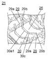
- FIG. 4A is a perspective view of a tableware basket setter in the embodiment.
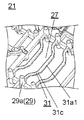
- FIG. 4B is a perspective view of an inner bowl set part of the tableware basket in the embodiment.
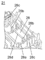
- FIG. 4C is a perspective view of a dish set portion of the tableware basket in the same embodiment.
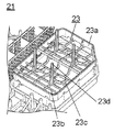
- FIG. 4D is a perspective view of a cup setting unit of the tableware basket in the embodiment.
- FIG. 5 is an enlarged view of a main part of the moss set unit.
- FIG. 6 is a cross-sectional view taken along the line 6-6 in FIG.
- FIG. 7A is a perspective view of another shape of the connecting member of the tableware basket in the embodiment.
- FIG. 7B is a perspective view of still another shape of the connecting member of the tableware basket in the embodiment.
- FIG. 8 is a perspective view of a connecting member of the dishwasher of the dishwasher according to Embodiment 2 of the present invention.
- FIG. 9 is a longitudinal sectional view of a conventional dishwasher.
- FIG. 10 is a top view of a tableware basket of a conventional dishwasher.
- Embodiment 1 the dishwasher in Embodiment 1 of this invention is demonstrated using drawing.
- a built-in dishwasher installed under the kitchen counter will be described as an example, but it is needless to say that the present invention is not limited to this.
- FIG. 1 is a longitudinal sectional view of a dishwasher according to Embodiment 1 of the present invention.
- FIG. 2 is a perspective view of the dish basket of the dishwasher in the same embodiment.
- the basic configuration of the dishwasher is the same as that of the dishwasher described with reference to FIG.
- the dishwasher includes at least a washing tub 2, a dish basket 21, and the like inside a housing 16.
- the housing 16 has a main body opening 15 at the front.
- the cleaning tank 17 is provided in the housing 16 so as to be movable back and forth via the main body opening 15.
- the cleaning tank 17 is provided with a door 18 and a cleaning tank opening 19, and a table basket 21 on which the tableware 20 is placed is disposed.
- the door body 18 is provided in front of the cleaning tank 17 and covers the main body opening 15.
- the cleaning tank opening 19 is provided in the upper part of the cleaning tank 17.
- the tableware basket 21 includes a tableware basket body 22, a cup set unit 23, an accessory case 25, and the like.
- the tableware basket main body 22 is integrally formed of resin.
- the cup set unit 23 is configured to be detachable from the tableware basket main body 22.
- the accessory case 25 accommodates elongate cutlery such as chopsticks and spoons.
- a leftover filter (not shown) that collects leftovers washed away from the dishes is disposed below the cup set unit 23. And by removing the cup set part 23, it is comprised so that extraction of a leftovers filter is possible, and a leftover can be processed.
- FIG. 3 is a top view of the dishwasher of the dishwasher according to the embodiment.
- the tableware basket 21 is composed of a tableware basket body 22 that is integrally formed of resin.
- the table basket main body 22 has, for example, a bowl set part 26 on the left side in FIG. 3, a bowl set part 27 on the lower center part, a dish set part 28 on the right side, and an accessory case 25 on the upper center part. Has been placed. Further, a cup set unit 23 is disposed on the right side of the accessory case 25. And between each set part of the tableware basket main body 22, and the outer periphery are divided by the frame-shaped member 22a. At this time, the tableware 20 such as the bowl 20a, the bowl 20b, and the dish 20c is placed sideways on the bowl set 26, the bowl set 27, and the dish set 28, respectively. Further, the cups 20d are placed on the cup set unit 23 with the drinking mouth facing downward.
- FIG. 4A is a perspective view of a tableware basket set portion in the same embodiment.
- FIG. 4B is a perspective view of an inner bowl set part of the tableware basket in the embodiment.
- FIG. 4C is a perspective view of a dish set portion of the tableware basket in the same embodiment.
- FIG. 4D is a perspective view of a cup setting unit of the tableware basket in the embodiment.
- FIG. 5 is an enlarged view of a main part of a tableware basket bowl set unit according to the embodiment. 6 is a cross-sectional view taken along the line 6-6 in FIG.
- the moss set portion 26 is configured by forming a support member 29 and a connecting member 30 that connects the support members 29 in a plurality of rows.
- the support member 29 supports two lower portions of the bowl 20a placed sideways, and details will be described later.
- the support member 29 includes a support portion 29a that supports the lower portion of the cage 20a from below and a support pin 29b that supports the cage 20a from the front.
- the central portion of the connecting member 30 is located at a position corresponding to the hill 20a1 on the surface (outer end surface 30c) side opposite to the surface (inner end surface) facing the hill 20a1 of the bowl 20a of the connecting member 30.
- the connecting member 30 is formed in a shape simulating the cross-sectional shape of the pot 20a to be placed when viewed from above shown in FIG.
- the cross-sectional shape of the rod 20a is a cross section when the rod 20a placed horizontally is cut in the horizontal direction in the vicinity of the center position.
- the cross-sectional shape of the connection member 30 imitating the bowl 20a which has a hill may include the shape (for example, U shape etc.) of the outline part of a hill bottom side. The same applies to the middle pots described below.
- the middle bowl set part 27 is also composed of a support member 29 having a support pin 29b and a connecting member 31, like the bowl 20a.
- the central part of the connecting member 31 has a plateau at a position corresponding to the plateau on the surface (outer end surface 31c) side opposite to the surface (inner end surface) facing the plateau of the middle bowl 20b of the connecting member 31.
- Convex shape 31a1 imitating the shape of a plateau of tableware 10 such as middle bowl 20b is provided. That is, the connecting member 31 is formed in a shape simulating the cross-sectional shape of the placed medium pot 20b.
- the cross-sectional shape of the medium pot 20b is a cross section when the medium pot 20b placed horizontally is cut in the horizontal direction in the vicinity of the center position.
- the dish set unit 28 is configured by arranging a support pin A 28b on a support part 28a that supports the lower part of the dish 20c shown in FIG. 3, and support pins B 28c on both outer sides thereof.
- the support pins B28c of the dish set portion 28 are linearly connected when viewed from above shown in FIG. 3, and are connected by a connecting member 28d having an arc shape when viewed from the side shown in FIG. Yes.
- the cup set portion 23 is constituted by a frame body 23a and a bar-like member 23b.
- the bar-like member 23b is provided so as to be inclined so that the cups 20d can be placed obliquely.
- the bottom of the cups 20d is arranged so as to be inclined outwardly from the tableware basket 21 from the opening.
- a ring-shaped member 23c is formed at each set position of the cups 20d of the cross-shaped member 23b. Thereby, a user can recognize that it is a mounting place of the cups 20d.
- the support member 23b is provided with a cup support pin 23d for supporting the inside of the cup 20d to be placed at each set position.
- the dishwasher of the dishwasher according to the present embodiment is configured. Accordingly, the user can easily visually recognize what and how to place the tableware basket 21 at what position.
- the user checks the set position when placing the tableware 20 on the tableware basket 21.
- the connecting members 30 and 31 simulating the shapes of the dishes are provided at the set positions of the dishes 20 such as the bowls 20a, the bowls 20b, and the dishes 20c.
- a ring-shaped member 23c is formed at the set position of the cups 20d. Therefore, the user can recognize the set position and set direction of the tableware 20 intuitively. As a result, the time for placing the tableware 20 can be shortened.
- the dishwasher normally sets the direction of the wash water sprayed from the spray nozzle 7 with respect to the correct set position of the dishes 20. In other words, when the tableware 20 is placed in the wrong direction, the tableware 20 cannot be effectively washed with the cleaning water, and the cleaning performance may be deteriorated.
- the user can intuitively recognize the set direction of the tableware 20. Therefore, the tableware can be placed without making a mistake in the setting position and the setting direction of the tableware 20. As a result, it is possible to realize a dishwasher capable of maintaining the high cleaning performance and exhibiting the original cleaning performance.
- the tableware basket 21 is divided according to the type of tableware by the frame-shaped member 22a. Therefore, the set place of the tableware 20 can be recognized more easily.
- FIGS. 5 and 6 show, as an example, a state where the moss 20a is placed on the moss set unit 26.
- the moss 20a has two lower portions B and C supported by the support portion 29a from below and supported from the front by the root of the support pin 29b (near the support portion 29a). Further, the rear side of the cage 20a is supported from both sides D and E by the tip portions of the two rear support pins 29b in the array. Thereby, the moss 20a can be set to the mosquito set part 26 in a stable and laterally independent manner.
- the cross-sectional shape of the connecting member 30 is a shape in which the lower surface side of the connecting member 30 is chamfered 30a2 with respect to the setting direction of the tableware. Accordingly, when the tableware is inserted and placed between the connecting members 30 of the pottery set portion 26, the connecting members 30 can be placed smoothly without getting in the way.
- the chamfer 30a2 of the connecting member 30 is formed, for example, along the direction of the wash water jetted obliquely from the jet nozzle 7 provided below, so that shielding of the wash water can be minimized. .
- the height positions (positions in the horizontal plane) of the plurality of connecting members 30 and 31 are all the same.
- the cups 20d such as cups and hot water are set in the bowl set portion 26, it is possible to stably place them on the connecting member 30.
- the movement of the cups 20d can be restricted by the support pins 29b of the support member 29.
- the tableware basket body 22 is integrally formed of resin, and the support pins are connected by a connecting member. Thereby, the rigidity of tableware basket 21 itself can be improved and the shape of tableware basket 21 can be maintained stably.
- the shape of the connecting member 30 has been described as an example of the shape of the cross-sectional shape of the tableware 20 to be set, but is not limited thereto.
- the connecting member 30a having an arc shape shown in FIG. 7A or the connecting member 30b having a trapezoidal shape shown in FIG. 7B may be used, and similar effects can be obtained.
- the table basket 21 is made of resin and the connecting member is made of resin.
- the present invention is not limited to this.
- a tableware basket, a connecting member, or the like may be configured with a wire, and the same effect can be obtained.
- the present invention is not limited to this, and the tableware 20 can be supported if it can be stably supported.
- the number of points may be arbitrary.
- FIG. 8 is a perspective view of the connecting member of the dishwasher of the dishwasher according to the second embodiment of the present invention.
- the dishwasher according to the present embodiment is not provided with a convex shape simulating the plateau shape of the tableware provided in the connecting member of the first embodiment, and the inner end surface of the curved surface of the connecting member 32.
- a concave shape 32b is provided in 32a. Since other configurations, operations and actions are the same as those in the first embodiment, detailed description thereof is omitted.
- the connecting member 32 includes a concave shape 32 b on the inner end surface 32 a near the center of the connecting member 32 that connects the support members 33.
- the cross-sectional shape of the connecting member 32 has a shape imitating the curved shape of tableware having a hill, for example.
- the cross-sectional shape of the connection member 32 imitating the curved shape of the tableware which has a hill may include the shape of the outline part of a hill bottom side.
- the concave shape 32b provided in the connection member 32 is provided in the position corresponding to a plateau on the surface (inner end surface 32a) side which opposes the plateau of the connection member 32.
- a thin projection area is formed in the vicinity of the center of the connecting member 32. Thereby, the amount of cleaning water shielded by the connecting member 32 can be further reduced. As a result, the washing performance of the dishwasher can be further improved.
- the shape of the connecting member 32 is described as an example of the shape simulating the cross-sectional shape of the tableware to be set, but is not limited thereto.
- the shape of the connecting member may be changed according to the design of the tableware basket or the type of tableware to be placed.
- the concave shape 32b may be provided in the arc-shaped connecting member 30a shown in FIG. 7A or the trapezoidal connecting member 30b shown in FIG. can get.
- the connecting member 32 may be further provided with a convex shape.
- the width between the convex support pins is preferably larger than the width of the concave shape.
- the dishwasher of the present invention includes a tableware basket in which the tableware is placed sideways, and the tableware basket includes a support member that supports the tableware in at least two places, and a connecting member that connects the support members. And have.
- the connecting member has a shape simulating the cross-sectional shape of the tableware having the hill between the support members, and protrudes to a position corresponding to the hill on the surface side opposite to the surface of the linking member facing the tabletop. You may have a shape.
- the dishwasher of the present invention includes a tableware basket on which the tableware is placed sideways, and the tableware basket includes a support member that supports the tableware in at least two places, and a connecting member that connects the support members.
- the connecting member has a shape imitating the curved shape of the tableware having the hill between the support members, and has a concave shape at a position corresponding to the hill on the surface side facing the tabletop of the tableware of the connecting member. May be.
- the present invention can intuitively recognize the type of tableware that can be placed by the user and the direction in which it is placed, the setability of the tableware is improved. Therefore, it is useful for a tableware basket installed in a dishwasher or a tableware dryer in which good operability is desired without deteriorating the cleaning performance.
Landscapes
- Washing And Drying Of Tableware (AREA)
Abstract
本発明の食器洗い機は、食器を横向きに立てて載置する食器かご(21)を備え、食器かご(21)は、食器を少なくとも2ヶ所で支持する支持部材(29)と、支持部材(29)を繋ぐ連結部材(30、31)とを有する。そして、連結部材(30、31)は、支持部材(29)間において、高台を有する食器の断面形状を模した形状を有し、連結部材(30、31)の食器の高台と対向する面と反対の面側で、高台に対応する位置に凸形状(30a1、31a1)を有する。これにより、食器かご(21)に載置できる食器の種類や載置する方向を直感的に認識できるため、食器のセット性が向上する。
Description
本発明は、食器類を洗浄する食器洗い機に関し、特に、食器が載置される食器かごに関する。
従来、この種の食器洗い機として、洗浄水を洗浄ノズルより食器に向けて噴射して食器を洗浄する食器洗い機が提案されている(例えば、特許文献1参照)。
以下に、特許文献1に記載の食器洗い機の構成について、図9を用いて説明する。図9は、従来の食器洗い機の縦断面図である。
図9に示すように、従来の食器洗い機は、食器洗い機本体1の内部に設けられた、少なくとも洗浄槽2と、洗浄ポンプ3と、洗浄モータ4と、残菜フィルタ5と、ヒータ6と、噴射穴8を有する噴射ノズル7と、食器かご9などから構成されている。洗浄ポンプ3は、洗浄槽2内の洗浄水を循環させる。このとき、洗浄ポンプ3は、洗浄槽2の底部外方に配設される洗浄モータ4により回転駆動される。残菜フィルタ5は、洗浄槽2の底部に配設される。ヒータ6は、洗浄槽2の底部に設けられ、残菜フィルタ5を通して洗浄ポンプ3により吸い込まれた洗浄水を加熱する。噴射ノズル7は、洗浄ポンプ3の吐出側より圧送された、加熱された洗浄水を噴射穴8から噴射する。食器かご9は、洗浄する食器10が載置され、噴射ノズル7の噴射穴8から噴射された噴射水流により、食器10が洗浄される。
つぎに、従来の食器洗い機の食器かごの構成について、図10を用いて説明する。図10は、従来の食器洗い機の食器かごの上面図である。
図10に示すように、従来の食器洗い機の食器かご9は、ワイヤー11aにより格子状に構成されている。そして、食器かご9には、ワイヤー11aを上部に突出させて配置した皿類セット部11と、樹脂製の碗類セットかご13が着脱可能に取り付けられている。碗類セットかご13は、図10に示す左右に複数の支持ピン14が配置されている。これにより、碗類セットかご13は、様々な形状の碗類を載置することができる。具体的には、使用者が碗類セットかご13に碗類を載置する場合、様々な食器の形状に対して、複数の支持ピン14の支持位置を変えることにより、それぞれの食器を安定して載置できる。
また、碗類セットかご13は、樹脂製で構成されているため、使用者が食器を載置するときに碗類セットかご13に接触してもソフトな感触が得られる。さらに、指が、碗類セットかご13の支持ピン14の先に当たっても痛くないという利点がある。
しかしながら、従来の食器洗い機の食器かご9の構成では、使用者が食器を載置する場合、様々な形状を有する食器10をどこに載置してよいか認識しにくいという課題があった。その理由は、食器かご9全体を見たときに、皿類セット部11や碗類セットかご13には、単に数多くの支持ピンが林立していることに起因する。
また、食器かご9の正しいセット位置が認識しにくいため、食器10が正しい方向や姿勢で載置できない。そのため、食器10に洗浄水を的確に当てることが困難となる。その結果、食器洗い機の洗浄性能が低下するという課題があった。
上記課題を解決するために、本発明の食器洗い機は、食器を横向きに立てて載置する食器かごを備え、食器かごは、食器を少なくとも2ヶ所で支持する支持部材と、支持部材を繋ぐ連結部材とを有する。そして、連結部材は、支持部材間において、高台を有する食器の断面形状を模した形状を有し、連結部材の食器の高台と対向する面と反対の面側で、高台に対応する位置に凸形状を有する。
これにより、使用者は、載置できる食器の種類や載置する方向を、直感的に認識できる。その結果、食器かごへの食器のセット性が向上するとともに、使い勝手が良く本来の洗浄性能が発揮できる食器洗い機を実現できる。
以下、本発明の実施の形態について、図を参照しながら説明する。なお、この実施の形態によって本発明が限定されるものではない。
(実施の形態1)
以下、本発明の実施の形態1における食器洗い機について、図面を用いて説明する。なお、本実施の形態では、キッチンカウンタの下に設置されるビルトイン型食器洗い機を例に説明するが、これに限られないことはいうまでもない。
以下、本発明の実施の形態1における食器洗い機について、図面を用いて説明する。なお、本実施の形態では、キッチンカウンタの下に設置されるビルトイン型食器洗い機を例に説明するが、これに限られないことはいうまでもない。
はじめに、本実施の形態の食器洗い機の構成について、図1および図2を用いて説明する。
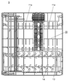
図1は、本発明の実施の形態1における食器洗い機の縦断面図である。図2は、同実施の形態における食器洗い機の食器かごの斜視図である。なお、食器洗い機の基本的な構成は、図9を用いて説明した食器洗い機と同様である。
図1に示すように、本実施の形態の食器洗い機は、筐体16の内部に、少なくとも洗浄槽2と、食器かご21などを備えて構成されている。筐体16は、前方に本体開口部15を有する。洗浄槽17は、筐体16内に本体開口部15を介して、前後に移動可能に設けられる。
また、洗浄槽17は、扉体18と、洗浄槽開口部19が設けられ、内部に食器類20を載置する食器かご21が配置されている。扉体18は、洗浄槽17の前方に設けられ、本体開口部15を覆う。洗浄槽開口部19は、洗浄槽17の上部に設けられている。
また、図2に示すように、食器かご21は、食器かご本体22と、コップ類セット部23と、小物入れ25などから構成される。食器かご本体22は、樹脂で一体に形成されている。コップ類セット部23は、食器かご本体22に着脱可能に構成される。小物入れ25は、箸やスプーンなどの細長いカトラリー類を立てて収容する。このとき、コップ類セット部23の下方には、食器類から洗い流された残菜を捕集する残菜フィルタ(図示せず)が配置されている。そして、コップ類セット部23を取り外すことにより、残菜フィルタの取り出しが可能に構成され、残菜を処理できる。
以下に、本実施の形態の食器洗い機のポイントである食器かごの構成について、図3を用いて説明する。
図3は、同実施の形態における食器洗い機の食器かごの上面図である。
図3に示すように、食器かご21は、樹脂で一体に構成された食器かご本体22から構成されている。食器かご本体22には、例えば、図3の向かって左側に碗類セット部26、下側中央部に中鉢類セット部27、その右側に皿類セット部28、上側中央部に小物入れ25が配置されている。さらに、小物入れ25の右側には、コップ類セット部23が配置されている。そして、食器かご本体22のそれぞれのセット部間および外周は、枠状部材22aにより区分けされている。このとき、碗類20a、中鉢類20b、皿類20cなどの食器類20は、それぞれ碗類セット部26、中鉢類セット部27、皿類セット部28に横向きに立てて載置される。また、コップ類20dは、飲み口を下に向けて、コップ類セット部23に載置される。
つぎに、上記食器かごの食器かご本体の詳細な構成について、図3を参照しながら、図4Aから図6を用いて、説明する。
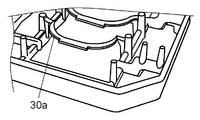
図4Aは、同実施の形態における食器かごの碗類セット部の斜視図である。図4Bは、同実施の形態における食器かごの中鉢類セット部の斜視図である。図4Cは、同実施の形態における食器かごの皿類セット部の斜視図である。図4Dは、同実施の形態における食器かごのコップ類セット部の斜視図である。図5は、同実施の形態における食器かごの碗類セット部の要部拡大図である。図6は、図3の6-6断面図である。
まず、図4A、図5および図6に示すように、碗類セット部26は、支持部材29と、支持部材29間を繋ぐ連結部材30とを、複数列で形成して構成される。支持部材29は、横向きに立てて載置される碗類20aの下部2ヶ所をそれぞれ支持するが、詳細は後述する。さらに、支持部材29は、碗類20aの下部を下方から支持する支持部29aと、碗類20aを前方から支持する支持ピン29bとから構成される。このとき、連結部材30の中央部は、連結部材30の碗類20aの高台20a1と対向する面(内側端面)と反対の面(外側端面30c)側で、高台20a1に対応する位置に、図6に示す高台20a1を有する碗類20aなどの食器10の高台20a1の形状を模した凸形状30a1を備えている。つまり、連結部材30は、図3に示す上方から見た場合に、載置される碗類20aの断面形状を模した形状で形成されている。なお、碗類20aの断面形状とは、横置きに載置された碗類20aを、中心位置近傍で水平方向に切断したときの断面である。なお、高台を有する碗類20aを模した連結部材30の断面形状とは、高台底辺の輪郭部分の形状(例えば、コの字形状など)を含んでもよいことはいうまでもない。以下で記述する、中鉢類においても同様である。
また、図4Bに示すように、中鉢類セット部27も、碗類20aと同様に、支持ピン29bを有する支持部材29と連結部材31とから構成されている。このとき、連結部材31の中央部は、連結部材31の中鉢類20bの高台と対向する面(内側端面)と反対の面(外側端面31c)側で、高台に対応する位置に、高台を有する中鉢類20bなどの食器10の高台の形状を模した凸形状31a1を備えている。つまり、連結部材31は、載置される中鉢類20bの断面形状を模した形状で形成されている。なお、中鉢類20bの断面形状とは、横置きに載置された中鉢類20bを、中心位置近傍で水平方向に切断したときの断面である。
また、図4Cに示すように、皿類セット部28は、図3に示す皿類20cの下部を支持する支持部28a上に支持ピンA28b、その外側の両側に支持ピンB28cが配置されて構成されている。そして、皿類セット部28の支持ピンB28c間は、図3に示す上方から見た場合、直線状で、図3に示す側面から見た場合、円弧形状を有する、連結部材28dで連結されている。
また、図4Dに示すように、コップ類セット部23は、枠体23aと桟状部材23bで構成されている。このとき、桟状部材23bは、コップ類20dを斜めに載置できるように傾斜して設けられている。具体的には、コップ類20dをコップ類セット部23にセットしたときに、コップ類20dの底部が、開口部より食器かご21の外方に傾斜して配置されるように形成されている。そして、桟状部材23bのコップ類20dの各セット位置には、リング状部材23cがそれぞれ形成されている。これにより、コップ類20dの載置場所であることを、使用者が認識することができる。さらに、桟状部材23bには、載置するコップ類20dの内部を支持するコップ類支持ピン23dが各セット位置に設けられている。
以上により、本実施の形態の食器洗い機の食器かごが構成されている。これにより、使用者は、食器かご21の、どの位置に、何を、どのように載置するかを視覚により、容易に認識することができる。
以下に。本実施の形態の食器洗い機の動作および作用について、図3から図6を参照しながら説明する。
まず、使用者は、食器類20を食器かご21に載置する際に、セット位置を確認する。このとき、碗類20a、中鉢類20b、皿類20cなどの食器類20のセット位置には、上述したように、それぞれの食器形状を模した連結部材30、31が設けられている。また、コップ類20dのセット位置には、リング状部材23cが形成されている。そのため、使用者は、直感的に、食器類20のセット位置やセット向きを認識できる。その結果、食器類20の載置時間を短縮できる。
また、通常、食器洗い機は、食器類20の正しいセット位置に対して、噴射ノズル7から噴射される洗浄水の噴射方向を設定している。つまり、間違った方向に食器類20を載置した場合、洗浄水で効果的に食器類20を洗えず、洗浄性能の低下を招く場合があった。
しかし、本実施の形態によれば、使用者は、直感的に、食器類20のセット方向を認識できる。そのため、食器類20の、セット位置やセット方向を間違えることなく食器の載置が可能となる。その結果、高い洗浄性能を維持して、本来の洗浄性能を発揮できる食器洗い機を実現できる。
また、本実施の形態によれば、食器かご21は、枠状部材22aにより、食器の種類ごとに区分けしている。そのため、食器類20のセット場所をさらに容易に認識できる。
以下に、本実施の形態の食器洗い機の食器かごにおいて、食器類の載置状態について、図5および図6を用いて詳細に説明する。なお、図5および図6は、一例として、碗類セット部26へ碗類20aを載置した状態を示している。
図5に示すように、碗類20aは、下部の2ヶ所B、Cが、下方から支持部29aで支持され、前方から支持ピン29bの根元(支持部29a近傍)で支持される。さらに、碗類20aの後方は、複数配列されている中の後ろの2本の支持ピン29bの先端部で両側D、Eから支持される。これにより、碗類20aは、横向きに安定して自立させて碗類セット部26にセットすることができる。
また、図6に示すように、連結部材30の断面形状は、食器のセット方向に対して、連結部材30の下面側を面取り30a2した形状としている。これにより、食器を碗類セット部26の連結部材30間に挿入して載置するときに、連結部材30が邪魔になることなく、スムーズに載置できる。
同時に、連結部材30の面取り30a2は、下方に設けた噴射ノズル7から、例えば斜めに噴射される洗浄水の方向に沿って形成されているので、洗浄水の遮蔽を最小限にすることができる。
また、複数の連結部材30、31の高さ位置(水平面内の位置)を全て同一としている。これにより、コップや湯のみなどのコップ類20dを碗類セット部26にセットする場合、連結部材30上に、安定に載置することが可能となる。さらに、支持部材29の支持ピン29bにより、コップ類20dの移動を制限することができる。
また、食器かご本体22を樹脂で一体に形成し、連結部材で各支持ピン間を連結して形成している。これにより、食器かご21自体の剛性を高めて、食器かご21の形状を安定に維持することができる。
なお、本実施の形態では、連結部材30の形状として、セットされる食器類20の断面形状を模した形状を例に説明したが、これに限られない。例えば、食器かご21のデザインや載置する食器の種類などに合わせて連結部材の形状を変更してもよい。具体的には、図7Aに示す円弧形状の連結部材30aや、図7Bに示す台形形状の連結部材30bなどとしてもよく、同様の効果が得られる。
また、本実施の形態では、食器かご21を樹脂で形成し、連結部材も樹脂製で形成した例で説明したが、これに限られない。例えば、食器かごや連結部材などをワイヤーで構成してもよく、同様の効果が得られる。
また、本実施の形態では、食器類20の下部や後方を支持する支持点が、2ヶ所ずつである場合を例に説明したが、これに限られず、食器類20を安定的に支持できれば支持点の数は任意でよい。
(実施の形態2)
以下に、本発明の実施の形態2の食器洗い機について、図8を用いて説明する。
以下に、本発明の実施の形態2の食器洗い機について、図8を用いて説明する。
図8は、本発明の実施の形態2における食器洗い機の食器かごの連結部材の斜視図である。
図8に示すように、本実施の形態の食器洗い機は、実施の形態1の連結部材に設けた食器類の高台形状を模した凸形状を設けず、連結部材32の湾曲した面の内側端面32aに凹形状32bを設けた点で、実施の形態1とは異なる。なお、それ以外の構成や、動作・作用は、実施の形態1と同様であるので、詳細な説明は省略する。
すなわち、図8に示すように、連結部材32は、支持部材33間を連結する連結部材32の中央部近傍の内側端面32aに、凹形状32bを備えている。このとき、実施の形態1と同様に、連結部材32の断面形状は、例えば高台を有する食器の湾曲形状を模した形状を有している。なお、高台を有する食器の湾曲形状を模した連結部材32の断面形状とは、高台底辺の輪郭部分の形状を含んでもよいことはいうまでもない。そして、連結部材32に設けた凹形状32bは、連結部材32の食器の高台と対向する面(内側端面32a)側で、高台に対応する位置に設けられている。
つまり、連結部材32の中央部近傍に投影面積の細い部分が形成される。これにより、連結部材32で遮蔽される洗浄水の量を、さらに少なくできる。その結果、食器洗い機の洗浄性能を、より向上できる。
なお、本実施の形態では、連結部材32の形状として、セットされる食器類の断面形状を模した形状を例に説明したが、これに限られない。例えば、食器かごのデザインや載置する食器の種類などに合わせて連結部材の形状を変更してもよい。具体的には、実施の形態1で説明した、図7Aに示す円弧形状の連結部材30aや、図7Bに示す台形形状の連結部材30bなどに凹形状32bを設けてもよく、同様の効果が得られる。
また、本実施の形態では、連結部材32の中央部近傍に凹形状32bのみを設けた例で説明したが、これに限られない。例えば、実施の形態1と組み合わせて、連結部材32に凸形状をさらに設けてもよい。この場合、凸形状の支持ピン間の幅を凹形状の幅より大きくすることが好ましい。これにより、連結部材の剛性の低下を抑制できる。
以上で説明したように、本発明の食器洗い機は、食器を横向きに立てて載置する食器かごを備え、食器かごは、食器を少なくとも2ヶ所で支持する支持部材と、支持部材を繋ぐ連結部材とを有する。そして、連結部材は、支持部材間において、高台を有する食器の断面形状を模した形状を有し、連結部材の食器の高台と対向する面と反対の面側で、高台に対応する位置に凸形状を有してもよい。
これにより、使用者は、載置できる食器の種類や載置する方向を、直感的に認識できる。その結果、食器かごへの食器のセット性が向上するとともに、使い勝手が良く本来の洗浄性能が発揮できる食器洗い機を実現できる。
また、本発明の食器洗い機は、食器を横向きに立てて載置する食器かごを備え、食器かごは、食器を少なくとも2ヶ所で支持する支持部材と、支持部材を繋ぐ連結部材と、を有する。そして、連結部材は、支持部材間において、高台を有する食器の湾曲形状を模した形状を有し、連結部材の食器の高台と対向する面側で、高台に対応する位置に凹形状を有してもよい。
これにより、洗浄ノズルから噴射される洗浄水の、連結部材で遮蔽される範囲を少なくして、遮蔽される洗浄水の量をさらに少なくできる。その結果、食器洗い機の洗浄性能を、より向上できる。
本発明は、使用者が載置できる食器の種類や載置する方向を直感的に認識できるので、食器のセット性が向上する。そのため、洗浄性能を低下させずに良好な操作性が要望される食器洗い機や食器乾燥機などに設置される食器かごなどに有用である。
1 食器洗い機本体
2,17 洗浄槽
3 洗浄ポンプ
4 洗浄モータ
5 残菜フィルタ
6 ヒータ
7 噴射ノズル
8 噴射穴
9,21 食器かご
10 食器
11,28 皿類セット部
11a ワイヤー
13 碗類セットかご
14,29b 支持ピン
15 本体開口部
16 筐体
18 扉体
19 洗浄槽開口部
20 食器類
20a 碗類
20a1 高台
20b 中鉢類
20c 皿類
20d コップ類
22 食器かご本体
22a 枠状部材
23 コップ類セット部
23a 枠体
23b 桟状部材
23c リング状部材
23d コップ類支持ピン
25 小物入れ
26 碗類セット部
27 中鉢類セット部
28a,29a 支持部
28b 支持ピンA
28c 支持ピンB
28d,30,30a,30b,31,32 連結部材
29,33 支持部材
30a1,31a1 凸形状
30a2 面取り
30c,31c 外側端面
32a 内側端面
32b 凹形状
2,17 洗浄槽
3 洗浄ポンプ
4 洗浄モータ
5 残菜フィルタ
6 ヒータ
7 噴射ノズル
8 噴射穴
9,21 食器かご
10 食器
11,28 皿類セット部
11a ワイヤー
13 碗類セットかご
14,29b 支持ピン
15 本体開口部
16 筐体
18 扉体
19 洗浄槽開口部
20 食器類
20a 碗類
20a1 高台
20b 中鉢類
20c 皿類
20d コップ類
22 食器かご本体
22a 枠状部材
23 コップ類セット部
23a 枠体
23b 桟状部材
23c リング状部材
23d コップ類支持ピン
25 小物入れ
26 碗類セット部
27 中鉢類セット部
28a,29a 支持部
28b 支持ピンA
28c 支持ピンB
28d,30,30a,30b,31,32 連結部材
29,33 支持部材
30a1,31a1 凸形状
30a2 面取り
30c,31c 外側端面
32a 内側端面
32b 凹形状
Claims (2)
- 食器を横向きに立てて載置する食器かごを備え、
前記食器かごは、
前記食器を少なくとも2ヶ所で支持する支持部材と、
前記支持部材を繋ぐ連結部材と、を有し、
前記連結部材は、前記支持部材間において、高台を有する前記食器の断面形状を模した形状を有し、前記連結部材の前記食器の前記高台と対向する面と反対の面側で、前記高台に対応する位置に凸形状を有する食器洗い機。 - 食器を横向きに立てて載置する食器かご、を備え、
前記食器かごは、
前記食器を少なくとも2ヶ所で支持する支持部材と、
前記支持部材を繋ぐ連結部材と、を有し、
前記連結部材は、前記支持部材間において、高台を有する前記食器の湾曲形状を模した形状を有し、前記連結部材の前記食器の前記高台と対向する面側で、前記高台に対応する位置に凹形状を有する食器洗い機。
Priority Applications (2)
| Application Number | Priority Date | Filing Date | Title |
|---|---|---|---|
| CN201380052818.1A CN104703527B (zh) | 2012-10-10 | 2013-10-09 | 餐具清洗机 |
| EP13845922.7A EP2907442B1 (en) | 2012-10-10 | 2013-10-09 | Tableware washing apparatus |
Applications Claiming Priority (2)
| Application Number | Priority Date | Filing Date | Title |
|---|---|---|---|
| JP2012-224783 | 2012-10-10 | ||
| JP2012224783A JP5982644B2 (ja) | 2012-10-10 | 2012-10-10 | 食器洗い機 |
Publications (1)
| Publication Number | Publication Date |
|---|---|
| WO2014057665A1 true WO2014057665A1 (ja) | 2014-04-17 |
Family
ID=50477147
Family Applications (1)
| Application Number | Title | Priority Date | Filing Date |
|---|---|---|---|
| PCT/JP2013/006011 Ceased WO2014057665A1 (ja) | 2012-10-10 | 2013-10-09 | 食器洗い機 |
Country Status (5)
| Country | Link |
|---|---|
| EP (1) | EP2907442B1 (ja) |
| JP (1) | JP5982644B2 (ja) |
| CN (1) | CN104703527B (ja) |
| TW (1) | TWI568401B (ja) |
| WO (1) | WO2014057665A1 (ja) |
Cited By (3)
| Publication number | Priority date | Publication date | Assignee | Title |
|---|---|---|---|---|
| ITTO20131097A1 (it) * | 2013-12-31 | 2015-07-01 | Indesit Co Spa | Accessorio di cesto di lavastoviglie |
| JP2016032567A (ja) * | 2014-07-31 | 2016-03-10 | リンナイ株式会社 | 食器洗浄乾燥機 |
| CN110638397A (zh) * | 2018-06-27 | 2020-01-03 | 青岛海尔洗碗机有限公司 | 一种盛放成套餐具的洗碗机搁架 |
Families Citing this family (6)
| Publication number | Priority date | Publication date | Assignee | Title |
|---|---|---|---|---|
| JP6442704B2 (ja) * | 2014-02-28 | 2018-12-26 | パナソニックIpマネジメント株式会社 | 食器洗い機 |
| US10149595B2 (en) | 2016-11-07 | 2018-12-11 | Whirlpool Corporation | Utensil rack for a dishwasher |
| CN110638395A (zh) * | 2018-06-27 | 2020-01-03 | 青岛海尔洗碗机有限公司 | 一种盛放成套餐具的洗碗机搁架 |
| CN110811476B (zh) * | 2018-08-13 | 2022-10-04 | 青岛海尔洗碗机有限公司 | 一种碗篮及洗碗机 |
| TWI749858B (zh) * | 2020-11-10 | 2021-12-11 | 江家羚 | 洗盤機 |
| CN116530904B (zh) * | 2023-05-05 | 2025-12-12 | 宁波小乎科技有限公司 | 一种茶杯清洗机 |
Citations (5)
| Publication number | Priority date | Publication date | Assignee | Title |
|---|---|---|---|---|
| JPS4960945U (ja) * | 1972-09-09 | 1974-05-29 | ||
| JPH01138366U (ja) * | 1988-03-17 | 1989-09-21 | ||
| JPH03215233A (ja) | 1990-01-19 | 1991-09-20 | Matsushita Electric Ind Co Ltd | 食器洗い機 |
| JPH1014854A (ja) * | 1996-07-05 | 1998-01-20 | Nakanishi Seisakusho:Kk | 給食用食器篭 |
| JPH11342103A (ja) * | 1998-04-03 | 1999-12-14 | Toto Ltd | 食器洗い機 |
Family Cites Families (4)
| Publication number | Priority date | Publication date | Assignee | Title |
|---|---|---|---|---|
| JPS4960945A (ja) * | 1972-10-14 | 1974-06-13 | ||
| JP4241788B2 (ja) * | 2006-09-08 | 2009-03-18 | パナソニック株式会社 | 食器洗い機 |
| DE102009027616A1 (de) * | 2009-07-10 | 2011-01-13 | BSH Bosch und Siemens Hausgeräte GmbH | Haushaltsgeschirrspülmaschine |
| CN202122562U (zh) * | 2011-07-06 | 2012-01-25 | 李创健 | 用于家用洗碗机中冲洗餐具的装置 |
-
2012
- 2012-10-10 JP JP2012224783A patent/JP5982644B2/ja active Active
-
2013
- 2013-10-09 WO PCT/JP2013/006011 patent/WO2014057665A1/ja not_active Ceased
- 2013-10-09 TW TW102136555A patent/TWI568401B/zh active
- 2013-10-09 EP EP13845922.7A patent/EP2907442B1/en not_active Not-in-force
- 2013-10-09 CN CN201380052818.1A patent/CN104703527B/zh active Active
Patent Citations (5)
| Publication number | Priority date | Publication date | Assignee | Title |
|---|---|---|---|---|
| JPS4960945U (ja) * | 1972-09-09 | 1974-05-29 | ||
| JPH01138366U (ja) * | 1988-03-17 | 1989-09-21 | ||
| JPH03215233A (ja) | 1990-01-19 | 1991-09-20 | Matsushita Electric Ind Co Ltd | 食器洗い機 |
| JPH1014854A (ja) * | 1996-07-05 | 1998-01-20 | Nakanishi Seisakusho:Kk | 給食用食器篭 |
| JPH11342103A (ja) * | 1998-04-03 | 1999-12-14 | Toto Ltd | 食器洗い機 |
Non-Patent Citations (1)
| Title |
|---|
| See also references of EP2907442A4 * |
Cited By (4)
| Publication number | Priority date | Publication date | Assignee | Title |
|---|---|---|---|---|
| ITTO20131097A1 (it) * | 2013-12-31 | 2015-07-01 | Indesit Co Spa | Accessorio di cesto di lavastoviglie |
| WO2015101879A1 (en) * | 2013-12-31 | 2015-07-09 | Indesit Company S.P.A. | Dishwasher rack accessory |
| JP2016032567A (ja) * | 2014-07-31 | 2016-03-10 | リンナイ株式会社 | 食器洗浄乾燥機 |
| CN110638397A (zh) * | 2018-06-27 | 2020-01-03 | 青岛海尔洗碗机有限公司 | 一种盛放成套餐具的洗碗机搁架 |
Also Published As
| Publication number | Publication date |
|---|---|
| CN104703527B (zh) | 2017-04-05 |
| JP5982644B2 (ja) | 2016-08-31 |
| TWI568401B (zh) | 2017-02-01 |
| CN104703527A (zh) | 2015-06-10 |
| EP2907442A4 (en) | 2015-11-25 |
| TW201438656A (zh) | 2014-10-16 |
| JP2014076138A (ja) | 2014-05-01 |
| EP2907442B1 (en) | 2017-06-14 |
| EP2907442A1 (en) | 2015-08-19 |
Similar Documents
| Publication | Publication Date | Title |
|---|---|---|
| JP5982644B2 (ja) | 食器洗い機 | |
| CN101573066B (zh) | 洗碗机及其支架组件 | |
| CN101947094B (zh) | 家用洗碗机 | |
| JP6948517B2 (ja) | 食器洗い機 | |
| KR102590134B1 (ko) | 랙 어셈블리 및 이를 갖는 식기세척기 | |
| CN206381154U (zh) | 一种搁架及安装有该搁架的洗碗机 | |
| JP6442704B2 (ja) | 食器洗い機 | |
| CN116600693B (zh) | 用于洗碗机设备的物品保持器组件 | |
| CN101416859A (zh) | 洗碗机 | |
| JP2015160028A (ja) | 食器洗い機 | |
| JP6340544B2 (ja) | 食器洗い機 | |
| KR20060100702A (ko) | 수저류 수납 구조가 구비된 식기 세척기 | |
| KR20080012597A (ko) | 식기 세척기의 랙 | |
| JP6883732B2 (ja) | 食器洗い機 | |
| TWI292705B (ja) | ||
| KR20140033693A (ko) | 식기 세척기 및 식기 세척기용 바스켓 | |
| JP2019030518A (ja) | 食器洗い機 | |
| JP2023039025A (ja) | 食器洗い機 | |
| JP2018027245A (ja) | 食器洗浄機 | |
| CN115299837A (zh) | 一种洗碗机搁架 | |
| JP2019030515A (ja) | 食器洗い機 | |
| JP6111410B2 (ja) | 食器洗い機 | |
| CN102197980A (zh) | 一种带有额外筐子的洗碗机 | |
| JP2003284671A (ja) | 食器洗い機 | |
| CN111184489B (zh) | 餐具清洗机 |
Legal Events
| Date | Code | Title | Description |
|---|---|---|---|
| 121 | Ep: the epo has been informed by wipo that ep was designated in this application |
Ref document number: 13845922 Country of ref document: EP Kind code of ref document: A1 |
|
| REEP | Request for entry into the european phase |
Ref document number: 2013845922 Country of ref document: EP |
|
| WWE | Wipo information: entry into national phase |
Ref document number: 2013845922 Country of ref document: EP |
|
| NENP | Non-entry into the national phase |
Ref country code: DE |