WO2014057713A1 - スクリーニング装置およびスクリーニング方法 - Google Patents
スクリーニング装置およびスクリーニング方法 Download PDFInfo
- Publication number
- WO2014057713A1 WO2014057713A1 PCT/JP2013/066442 JP2013066442W WO2014057713A1 WO 2014057713 A1 WO2014057713 A1 WO 2014057713A1 JP 2013066442 W JP2013066442 W JP 2013066442W WO 2014057713 A1 WO2014057713 A1 WO 2014057713A1
- Authority
- WO
- WIPO (PCT)
- Prior art keywords
- fine particles
- suction
- measurement chip
- well
- capillary
- Prior art date
- Legal status (The legal status is an assumption and is not a legal conclusion. Google has not performed a legal analysis and makes no representation as to the accuracy of the status listed.)
- Ceased
Links
Images










Classifications
-
- G—PHYSICS
- G01—MEASURING; TESTING
- G01N—INVESTIGATING OR ANALYSING MATERIALS BY DETERMINING THEIR CHEMICAL OR PHYSICAL PROPERTIES
- G01N21/00—Investigating or analysing materials by the use of optical means, i.e. using sub-millimetre waves, infrared, visible or ultraviolet light
- G01N21/75—Systems in which material is subjected to a chemical reaction, the progress or the result of the reaction being investigated
- G01N21/76—Chemiluminescence; Bioluminescence
-
- B—PERFORMING OPERATIONS; TRANSPORTING
- B01—PHYSICAL OR CHEMICAL PROCESSES OR APPARATUS IN GENERAL
- B01L—CHEMICAL OR PHYSICAL LABORATORY APPARATUS FOR GENERAL USE
- B01L3/00—Containers or dishes for laboratory use, e.g. laboratory glassware; Droppers
- B01L3/02—Burettes; Pipettes
- B01L3/021—Pipettes, i.e. with only one conduit for withdrawing and redistributing liquids
-
- G—PHYSICS
- G01—MEASURING; TESTING
- G01N—INVESTIGATING OR ANALYSING MATERIALS BY DETERMINING THEIR CHEMICAL OR PHYSICAL PROPERTIES
- G01N15/00—Investigating characteristics of particles; Investigating permeability, pore-volume or surface-area of porous materials
- G01N15/10—Investigating individual particles
- G01N15/14—Optical investigation techniques, e.g. flow cytometry
- G01N15/1429—Signal processing
- G01N15/1433—Signal processing using image recognition
-
- G—PHYSICS
- G01—MEASURING; TESTING
- G01N—INVESTIGATING OR ANALYSING MATERIALS BY DETERMINING THEIR CHEMICAL OR PHYSICAL PROPERTIES
- G01N21/00—Investigating or analysing materials by the use of optical means, i.e. using sub-millimetre waves, infrared, visible or ultraviolet light
- G01N21/01—Arrangements or apparatus for facilitating the optical investigation
- G01N21/03—Cuvette constructions
-
- G—PHYSICS
- G01—MEASURING; TESTING
- G01N—INVESTIGATING OR ANALYSING MATERIALS BY DETERMINING THEIR CHEMICAL OR PHYSICAL PROPERTIES
- G01N21/00—Investigating or analysing materials by the use of optical means, i.e. using sub-millimetre waves, infrared, visible or ultraviolet light
- G01N21/01—Arrangements or apparatus for facilitating the optical investigation
- G01N21/11—Filling or emptying of cuvettes
-
- G—PHYSICS
- G01—MEASURING; TESTING
- G01N—INVESTIGATING OR ANALYSING MATERIALS BY DETERMINING THEIR CHEMICAL OR PHYSICAL PROPERTIES
- G01N21/00—Investigating or analysing materials by the use of optical means, i.e. using sub-millimetre waves, infrared, visible or ultraviolet light
- G01N21/01—Arrangements or apparatus for facilitating the optical investigation
- G01N21/13—Moving of cuvettes or solid samples to or from the investigating station
-
- B—PERFORMING OPERATIONS; TRANSPORTING
- B01—PHYSICAL OR CHEMICAL PROCESSES OR APPARATUS IN GENERAL
- B01L—CHEMICAL OR PHYSICAL LABORATORY APPARATUS FOR GENERAL USE
- B01L2200/00—Solutions for specific problems relating to chemical or physical laboratory apparatus
- B01L2200/06—Fluid handling related problems
- B01L2200/0642—Filling fluids into wells by specific techniques
-
- B—PERFORMING OPERATIONS; TRANSPORTING
- B01—PHYSICAL OR CHEMICAL PROCESSES OR APPARATUS IN GENERAL
- B01L—CHEMICAL OR PHYSICAL LABORATORY APPARATUS FOR GENERAL USE
- B01L2200/00—Solutions for specific problems relating to chemical or physical laboratory apparatus
- B01L2200/06—Fluid handling related problems
- B01L2200/0647—Handling flowable solids, e.g. microscopic beads, cells, particles
-
- B—PERFORMING OPERATIONS; TRANSPORTING
- B01—PHYSICAL OR CHEMICAL PROCESSES OR APPARATUS IN GENERAL
- B01L—CHEMICAL OR PHYSICAL LABORATORY APPARATUS FOR GENERAL USE
- B01L2200/00—Solutions for specific problems relating to chemical or physical laboratory apparatus
- B01L2200/06—Fluid handling related problems
- B01L2200/0647—Handling flowable solids, e.g. microscopic beads, cells, particles
- B01L2200/0652—Sorting or classification of particles or molecules
-
- B—PERFORMING OPERATIONS; TRANSPORTING
- B01—PHYSICAL OR CHEMICAL PROCESSES OR APPARATUS IN GENERAL
- B01L—CHEMICAL OR PHYSICAL LABORATORY APPARATUS FOR GENERAL USE
- B01L2300/00—Additional constructional details
- B01L2300/06—Auxiliary integrated devices, integrated components
- B01L2300/0627—Sensor or part of a sensor is integrated
-
- B—PERFORMING OPERATIONS; TRANSPORTING
- B01—PHYSICAL OR CHEMICAL PROCESSES OR APPARATUS IN GENERAL
- B01L—CHEMICAL OR PHYSICAL LABORATORY APPARATUS FOR GENERAL USE
- B01L2300/00—Additional constructional details
- B01L2300/08—Geometry, shape and general structure
- B01L2300/0832—Geometry, shape and general structure cylindrical, tube shaped
- B01L2300/0838—Capillaries
-
- B—PERFORMING OPERATIONS; TRANSPORTING
- B01—PHYSICAL OR CHEMICAL PROCESSES OR APPARATUS IN GENERAL
- B01L—CHEMICAL OR PHYSICAL LABORATORY APPARATUS FOR GENERAL USE
- B01L2300/00—Additional constructional details
- B01L2300/16—Surface properties and coatings
- B01L2300/161—Control and use of surface tension forces, e.g. hydrophobic, hydrophilic
- B01L2300/165—Specific details about hydrophobic, oleophobic surfaces
-
- G—PHYSICS
- G01—MEASURING; TESTING
- G01N—INVESTIGATING OR ANALYSING MATERIALS BY DETERMINING THEIR CHEMICAL OR PHYSICAL PROPERTIES
- G01N15/00—Investigating characteristics of particles; Investigating permeability, pore-volume or surface-area of porous materials
- G01N15/10—Investigating individual particles
- G01N15/14—Optical investigation techniques, e.g. flow cytometry
- G01N15/149—Optical investigation techniques, e.g. flow cytometry specially adapted for sorting particles, e.g. by their size or optical properties
-
- G—PHYSICS
- G01—MEASURING; TESTING
- G01N—INVESTIGATING OR ANALYSING MATERIALS BY DETERMINING THEIR CHEMICAL OR PHYSICAL PROPERTIES
- G01N15/00—Investigating characteristics of particles; Investigating permeability, pore-volume or surface-area of porous materials
- G01N15/10—Investigating individual particles
- G01N2015/1006—Investigating individual particles for cytology
-
- G—PHYSICS
- G01—MEASURING; TESTING
- G01N—INVESTIGATING OR ANALYSING MATERIALS BY DETERMINING THEIR CHEMICAL OR PHYSICAL PROPERTIES
- G01N15/00—Investigating characteristics of particles; Investigating permeability, pore-volume or surface-area of porous materials
- G01N15/10—Investigating individual particles
- G01N15/14—Optical investigation techniques, e.g. flow cytometry
- G01N2015/1477—Multiparameters
-
- G—PHYSICS
- G01—MEASURING; TESTING
- G01N—INVESTIGATING OR ANALYSING MATERIALS BY DETERMINING THEIR CHEMICAL OR PHYSICAL PROPERTIES
- G01N21/00—Investigating or analysing materials by the use of optical means, i.e. using sub-millimetre waves, infrared, visible or ultraviolet light
- G01N21/01—Arrangements or apparatus for facilitating the optical investigation
- G01N21/03—Cuvette constructions
- G01N2021/0346—Capillary cells; Microcells
-
- G—PHYSICS
- G01—MEASURING; TESTING
- G01N—INVESTIGATING OR ANALYSING MATERIALS BY DETERMINING THEIR CHEMICAL OR PHYSICAL PROPERTIES
- G01N21/00—Investigating or analysing materials by the use of optical means, i.e. using sub-millimetre waves, infrared, visible or ultraviolet light
- G01N21/01—Arrangements or apparatus for facilitating the optical investigation
- G01N21/13—Moving of cuvettes or solid samples to or from the investigating station
- G01N2021/135—Sample holder displaceable
-
- G—PHYSICS
- G01—MEASURING; TESTING
- G01N—INVESTIGATING OR ANALYSING MATERIALS BY DETERMINING THEIR CHEMICAL OR PHYSICAL PROPERTIES
- G01N21/00—Investigating or analysing materials by the use of optical means, i.e. using sub-millimetre waves, infrared, visible or ultraviolet light
- G01N21/62—Systems in which the material investigated is excited whereby it emits light or causes a change in wavelength of the incident light
- G01N21/63—Systems in which the material investigated is excited whereby it emits light or causes a change in wavelength of the incident light optically excited
- G01N21/64—Fluorescence; Phosphorescence
- G01N21/645—Specially adapted constructive features of fluorimeters
- G01N21/6452—Individual samples arranged in a regular 2D-array, e.g. multiwell plates
-
- G—PHYSICS
- G01—MEASURING; TESTING
- G01N—INVESTIGATING OR ANALYSING MATERIALS BY DETERMINING THEIR CHEMICAL OR PHYSICAL PROPERTIES
- G01N2201/00—Features of devices classified in G01N21/00
- G01N2201/12—Circuits of general importance; Signal processing
-
- G—PHYSICS
- G01—MEASURING; TESTING
- G01N—INVESTIGATING OR ANALYSING MATERIALS BY DETERMINING THEIR CHEMICAL OR PHYSICAL PROPERTIES
- G01N2500/00—Screening for compounds of potential therapeutic value
- G01N2500/10—Screening for compounds of potential therapeutic value involving cells
-
- G—PHYSICS
- G01—MEASURING; TESTING
- G01N—INVESTIGATING OR ANALYSING MATERIALS BY DETERMINING THEIR CHEMICAL OR PHYSICAL PROPERTIES
- G01N35/00—Automatic analysis not limited to methods or materials provided for in any single one of groups G01N1/00 - G01N33/00; Handling materials therefor
- G01N35/02—Automatic analysis not limited to methods or materials provided for in any single one of groups G01N1/00 - G01N33/00; Handling materials therefor using a plurality of sample containers moved by a conveyor system past one or more treatment or analysis stations
- G01N35/028—Automatic analysis not limited to methods or materials provided for in any single one of groups G01N1/00 - G01N33/00; Handling materials therefor using a plurality of sample containers moved by a conveyor system past one or more treatment or analysis stations having reaction cells in the form of microtitration plates
Definitions
- a moving part that can be moved, a pump, and a suction / discharge capillary, and the suction / discharge capillary sucks the fine particles in the well provided in the measurement chip and puts it in a predetermined position on the receiving plate.
- a collecting portion for discharging and collecting wherein the outer diameter of the tip of the suction / discharge capillary is larger than the width of the well formed in the measuring chip, and the tip surface of the suction / discharge capillary is The suction / discharge capillary is inclined with respect to the upper surface of the measurement chip, and the target sample is located at a position where the distance between the tip of the suction / discharge capillary and the measurement chip is a predetermined distance. It is characterized by sucking fine particles.
- a moving part that can be moved, a pump, and a suction / discharge capillary, and the suction / discharge capillary sucks the fine particles in the well provided in the measurement chip and puts it in a predetermined position of the storage plate.
- the measurement unit acquires time variation of the fluorescence intensity of the fine particles as the optical information, and the analysis unit determines the fine particles to be collected based on the optical information.
- the outer dimension of the tip of the capillary is larger than the width of the well formed in the measuring chip, and the capillary has a predetermined distance between the tip and the measuring chip, and Fine particles are aspirated at a position where the central axis is shifted from the central axis of the well.
- Fine particles are aspirated at a position where the central axis is shifted from the central axis of the well.
- FIG. 1 It is a perspective view showing roughly the composition of the screening device concerning a 1st embodiment of the present invention.
- FIG. 1 is a side view schematically showing the configuration of the screening apparatus according to the first embodiment
- FIG. 2 is a perspective view of the screening apparatus of FIG.
- the screening apparatus 1 irradiates a plurality of fine particles (for example, cells of a living body) in the measurement chip 60 with light, and is a predetermined target sample based on fluorescence emitted from the fine particles.
- the fine particles in the well in which the fine particles satisfying the collection condition are accommodated are selectively sucked and collected in the accommodation plate 50.
- the support portion 12 and the support base 30 are fixed on the plate member 113 positioned at the top of the plurality of plate materials.
- the support part 12 is vertically arranged on the plate member 113 along the Z direction.
- the support base 30 has a leg portion 30a and a support plate 30b.
- the plate members 111, 112, 113 and the support plate 30b are arranged at a predetermined interval with respect to the Z direction.
- the moving unit 16 is placed and fixed on the support plate 30b of the support plate 30.
- a mounting table 40, a receiving plate 50, and a measuring chip 60 are mounted on the moving part 16.
- the moving unit 16 can position the mounting table 40, that is, the accommodation plate 50 and the measuring chip 60 by moving along the X direction and / or the Y direction.
- the moving unit 16 has a table 161 and a table 162 arranged on the table.
- the table 161 is fixed to the support base 30, and is mounted so that the table 162 can be positioned by moving along the X direction.
- the table 162 is mounted so that the mounting table 40 can be moved and moved along the Y direction.
- Guide rails 168 and 168 and a motor 169 are provided on the upper surface of the table 162.
- engagement members 170, 170 having a U-shaped cross section and a nut 171 are provided on the lower surface of the mounting table 40.
- the engaging members 170 and 170 are movably engaged with the guide rails 168 and 168, respectively.
- the feed screw 172 of the motor 169 is screwed with the nut 171.
- FIG. 4 is a perspective view showing the configuration of the receiving plate 50 and the measuring chip 60 on the mounting table 40 of FIG.
- the mounting table 40 is, for example, a rectangular plate-like member. On the mounting surface 41 of the mounting table 40, the receiving plate 50 and the measuring chip 60 can be detachably arranged side by side along the Y direction.
- the upper surface 60a of the measurement chip 60 is pressed against the inner lower surface 121a of the case part 121, whereby the upper surface 60a of the measurement chip 60 is positioned on the reference surface CL.
- the measuring chip 60 is formed of a light-transmitting material such as glass or plastic, and a large number of wells 61 are arranged on the matrix on the upper surface 60a.
- Each well 61 is, for example, a substantially trapezoidal or substantially cup-shaped recess in the vertical cross section, and the horizontal cross sectional shape of the well 61 is preferably substantially circular. Dispensing or batch-injecting the fine particles M has a size that allows one fine particle M to be stored.
- FIG. 6 is a perspective view showing the configuration of the collection unit 13 in FIG. 1
- FIG. 7 is a cross-sectional view showing the configuration of the operation unit in FIG.
- the collection unit 13 includes an operation unit 130 and a base 131, and the base 131 is fixed to the support unit 12.
- the operation unit 130 includes an actuator 132 (pump) and a suction / discharge capillary 140.
- the actuator 132 has an actuator main body 133 and a substantially cylindrical plunger 136 accommodated in the cylinder 134 of the actuator main body 133, and a predetermined fluid is pumped by the plunger 136 reciprocating in the cylinder 134. .
- a pipe line 135 communicating the cylinder 134 of the actuator body 133 and the suction / discharge capillary 140.
- the capillary 142 is a tapered hollow member whose diameter is reduced along the Z2 direction (downward direction), and a pipe line is formed in the inside thereof.
- the rear end 142 a of the capillary 142 is connected to the pipe line 135.
- the tip 142b of the capillary 142 is close to the well 61 of the measurement chip 60 when fine particles are sucked.
- the base 131 has a motor 151 disposed at the upper end of the base and a feed screw 152 attached to the motor.
- the feed screw 152 is screwed with a nut 137 of the operation unit 130.
- the motor 151 is electrically connected to the control unit 100, and the control unit 100 operates the motor 151 to rotate the feed screw 152, so that the operation unit 130 together with the nut 137 is in the Z direction (Z1 direction and Z2 direction). It moves up and down along the position.
- the measurement unit 14 irradiates the region including the plurality of wells 61 of the measurement chip 60 with the light L, thereby generating fluorescence from the fine particles M in the region and receiving the fluorescence (FIG. 1).
- the fluorescence from the received fine particles M is subjected to image analysis by the image analysis unit 15.
- the image analysis unit 15 calculates the fluorescence intensity of the fine particles M1 that emit fluorescence of at least the maximum luminance among the plurality of fine particles M in each well 61.
- the control unit 100 detects the position of the well 61 in which the fine particles M1 that emit fluorescence with the maximum luminance satisfying the collection condition are stored. Then, the control unit 100 gives a control drive signal to the motors 164 and 169 in FIG. 3 so that the well 61 of the measurement chip 60 on the moving unit 16 is positioned directly below the suction / discharge capillary 140. it can. That is, the suction / discharge capillary 140 is configured to be able to suck fine particles in the well with a specific well as a target.
- the suction / discharge capillary 140 can suck one or a plurality of fine particles from a selected well of the plurality of wells, that is, a well containing fine particles satisfying a predetermined recovery condition. It has become. Further, the suction / discharge capillary 140 can discharge the selected one or more fine particles to a predetermined well 51 of the accommodation plate 50.
- the measurement unit 14 irradiates the measurement chip 60 and the fine particles M accommodated in the measurement chip 60 with light guided from at least one light source, thereby transmitting the shape and position information by transmitted light, reflected light, or fluorescence.
- luminance information such as fluorescence and chemiluminescence is acquired with a resolution finer than the average size of each fine particle, and the shape of the measurement chip itself, the position coordinates and the size of the well 61 arranged on the measurement chip 60 are also obtained. Get information such as.
- the image analysis unit 15 analyzes the measured shape information and light information, and thereby at least data for confirming that the fine particles M1 satisfying the luminance condition that can be set by the measurer exist in each well 61. get. Then, the image analysis unit 15 extracts the light information from the fine particles by matching the position coordinate information of the well 61 with the transmitted light or reflected light and the light information of the fluorescence / chemiluminescence.
- the measurement unit 14 has an autofocus function, performs measurement in a focused state at a predetermined position, and determines the positional relationship between the tip 142b of the suction / discharge capillary 140 and the upper surface of the measurement chip 60. Can be determined by performing autofocus on
- the measuring unit 14 has an objective lens 110, and the objective lens 110 guides light to the measuring chip 60.
- the objective lens 110 is disposed below the measurement chip 60 and the moving unit 16, and the suction / discharge capillary 140 is disposed above the measurement chip 90 and the moving unit 16.
- the measuring chip 90 and its moving part 16 can be disposed between the objective lens 110 and the suction / discharge capillary 140.
- the excitation light source 181 is constituted by, for example, a laser light source or a mercury lamp.
- the shutter unit 182 is disposed between the excitation light source 181 and the fluorescent filter unit 183. When the shutter unit 182 does not irradiate the light L to the fine particles M of the measurement chip 60, the excitation light source 181 is generated. The light L to be blocked can be blocked before the fluorescent filter unit 183.
- the measurement unit 14 includes an excitation light source 181 as a light source, an optical filter (excitation filter) 184 for selecting only a desired excitation wavelength band from light emitted from the excitation light source 181, and a measurement chip. Fluorescence composed of an optical filter (fluorescence filter) 185 for selecting only a desired wavelength band of optical information from 60 and a dichroic mirror 186 for switching an optical path according to the difference in wavelength band between excitation light and optical information.
- the filter unit 183, the objective lens 110 for guiding the light emitted from the excitation light source 181 to the measurement chip 60 and collecting optical information obtained from the measurement chip 60, and the objective lens 110 are movable in the optical axis direction. Focus unit 187 having an autofocus function and light for detecting light information from a measurement target And a light receiving portion 188 of the output unit.
- the fluorescent filter unit 183 and the light receiving unit 188 are fixed to the fluorescent incident unit 190.
- the measurement unit 14 has a half mirror (not shown), and by switching between the half mirror and the fluorescence filter unit 183, a part of the light from the excitation light source 181 is irradiated onto the observation target and at the same time from the observation target.
- the shape and position information of the upper surface 60a of the measuring chip 60 and the well 61 formed on the upper surface can be measured.
- the plurality of objective lenses 110a, 110b,... Can be positioned at the lower position of the measurement chip 60 by rotating the objective lenses 110a, 110b,.
- the focus unit 187 operates the motor 189 in response to a command from the control unit 100 to move and position, for example, the objective lens 110 arranged at a position below the measurement chip 60 along the Z direction.
- the focus adjustment of the objective lens 110 with respect to the fine particles M of the measurement chip 60 can be performed.
- the inventors pay attention to the positional relationship and dimensions of the capillary 142 and the measurement chip 60, particularly at the time of suction, so that the collection unit 13 can measure the measurement chip 60. It has been found that the upper fine particles M can be accurately sucked. This will be described in detail below with reference to FIGS.
- FIG. 8 is a cross-sectional view showing the positional relationship between the capillary 142 and the well 61 during the fine particle suction operation.
- the tip 142 b of the capillary 142 has a substantially annular shape in cross section and has an end surface 144.
- the outside dimension of the tip of the capillary 142 is designed to be larger than the width of the well 61 formed in the measuring chip 60.
- the end surface 144 and the upper surface 60a of the measuring chip 60 are arranged at a distance L (L> 0), so that a flow path toward the capillary 142 is formed between the end surface 144 and the upper surface 60a during the suction operation. Will be formed.
- the capillary 142 is arranged so that the center axis C1 of the capillary 142 is shifted from the center axis C2 of the well 61.
- the distance between the center axis C1 of the capillary 142 and the center axis C2 of the well 61 is ⁇ ( ⁇ ⁇ 0).
- a flow path P1 and a flow path P2 longer than the flow path P1 are formed between the end surface 144 and the upper surface 60a.
- the tip 142b of the capillary 142 has a substantially cylindrical shape
- the outer radius of the tip 142b is Ro
- the inner radius is Ri
- the opening radius of the well 61 is Rw
- the radius of the fine particles M is Rc.
- the distance L between the capillary 142 and the well 61 is smaller than the diameter (2Rc) of the fine particles M (conditional expression (1)).
- the value obtained by subtracting the inner peripheral radius Ri from the outer peripheral radius Ro of the capillary 142 is larger than half the value of the distance L (conditional expression (2)), and the opening radius Rw of the well 61 from the outer peripheral radius Ro of the capillary 142. Is greater than half the distance L (conditional expression (3)).
- the distance ⁇ between the central axis C1 and the central axis C2 is preferably about 0.1 to 1 times the opening radius Rw of the well 61, for example. If comprised in this way, it will become easy to generate
- the distance ⁇ is more preferably about 0.2 to 0.4 times the opening radius Rw of the well 61. As a result, the fine particles M can be smoothly collected by the capillary 142.
- the inner peripheral radius Ri of the capillary is preferably about 0.8 to 2 times the opening radius Rw of the well 61.
- a pre-suction operation for sucking a certain amount of the liquid A is performed before the fine particles M are sucked. More effective.
- the suction control including the pre-suction operation is executed by the collection unit 13 and the control unit 100.
- the liquid layer A1 is formed in the capillary 142 before the capillary 142 reaches the position where the suction of the fine particles M is started. Therefore, even if the fine particles M are sucked immediately after the start of the suction operation, the fine particles M are not located on the liquid surface in the capillary 142, and the liquid layer A1 is located above the fine particles M.
- the liquid layer A1 plays a role of pressing the fine particles M downward from above, so that the fine particles M do not remain in the capillary 142. The phenomenon of adhering and remaining on the inner wall of 142 is prevented, and the discharge accuracy of the fine particles M is improved.
- the capillary 142 may be sucked from another container containing an arbitrary liquid, and this liquid may be different from the liquid A.
- this liquid may be different from the liquid A.
- step S1 information on the reference position of the measurement chip, correction parameters, and the like are obtained as the arrangement information of the measurement chip 60 (step S1). Thereafter, image analysis is performed, and the center position of each well is obtained. Coordinate information is acquired (step S2). Next, light is irradiated to obtain optical information of the fine particles (sample), and luminance analysis is performed (step S3).
- luminance analysis for example, as shown in FIG. 12D described later, a reaction solution may be introduced into each well to fluoresce fine particles in the well, and the time variation of the fluorescence information may be measured. Further, as shown in FIG. 15 described later, the number of fine particles contained in each well on the measurement chip 60 may be measured.
- a user can select a desired collection condition of fine particles, for example, a fluorescence whose brightness exceeds a predetermined threshold, or a plurality of fluorescence (for example, different fluorescence colors).
- a fluorescence whose brightness exceeds a predetermined threshold or a plurality of fluorescence (for example, different fluorescence colors).
- at least one fluorescence luminance exceeding a predetermined threshold or any combination thereof is used as the collection condition.
- those excluded from the collection (those lower than the threshold value) may be combined, and some conditions determined in this way are input (step S4), and the above collection conditions are satisfied.
- the fine particles are identified as the target specimen (step S5).
- the center position of the capillary is acquired by image analysis or the like, and the position shifted by the distance ⁇ from the center position is set as the center position (position information) of the well at the time of collecting fine particles (step S6). Then, the center position of each well in which the target sample is accommodated is moved so as to match the center position of the well at the time of collecting the fine particles set in step S6, and the target sample specified in step S5 is sequentially recovered (step S5). S7).
- the collected sample is stored in a predetermined well on the storage plate 50 set in advance by the user.
- the outer diameter of the tip of the capillary 142 is larger than the width of the well 60 formed in the measuring chip 60, and the capillary 142 has the tip 142 b and the measuring chip 60.
- the fine particles M are sucked at a position where the distance between the center axis C1 of the tip 142 and the center axis C2 of the well 61 is shifted. Thereby, the fine particles M can be accurately aspirated and collected in cell units.
- the upward unidirectional flow F3 can be generated in the well 61, so that it is not affected by the influence of the fluid resistance generated in the liquid A in the well 61, and the fine particle M that is the target specimen. Can be accurately sucked.
- the screening device of this embodiment is obtained by adding a mechanism for injecting liquid into the liquid holding unit or discharging liquid from the liquid holding unit to the screening device of the first embodiment.
- this 2nd Embodiment does not necessarily need to be equipped with the structure of the screening apparatus which concerns on 1st Embodiment, It is possible to implement independently, irrespective of the structure of 1st Embodiment.
- the case part 221 has a liquid holding part 229 for holding the liquid A, which is provided in the center part in the planar direction and above the measurement chip 60. And can hold various liquids such as a culture medium, a reagent, and a reaction liquid.
- the liquid holding unit 229 is a space defined by the inner side surface 221 a of the case unit 221 and the upper surface 60 a of the measurement chip 60.
- transducing part 230 is provided in the upper end vicinity of the one end side of the liquid holding
- the liquid introduction unit 230 introduces a predetermined liquid into the liquid holding unit 229, and the liquid discharge unit 231 discharges the predetermined liquid held in the liquid holding unit 229. Further, the liquid introduction unit 230 and the liquid discharge unit 231 are configured to be able to execute the discharge / introduction operation at the same time. For example, when the medium G is held in the liquid holding unit 229, the reaction liquid H is introduced into the liquid holding unit 229 by the liquid introduction unit 230 while the medium G is discharged to the outside by the liquid discharge unit 231.
- a liquid such as a reagent is dropped into each well I1 in a state in which the medium G is discharged to the outside by a predetermined amount until the liquid level of the medium G reaches the upper surface of the measurement chip or its vicinity.
- a dropping unit 232 for dropping may be provided (FIG. 12B), or a liquid such as a reagent containing a plurality of wells in a state where a predetermined amount of the medium G is discharged to the upper surface of the measurement chip.
- You may provide the spray part 233 sprayed as mist I2 with respect to an area
- the mist amount of the mist I2 is large in the well close to the case portion 221, and the mist amount of the mist I2 decreases as the distance from the case portion 221 increases.
- the attachment position of the spray unit 233 with respect to the measurement chip 60 it is possible to vary the concentration of the mist I2 introduced into each well.
- the image analysis unit 15 may continuously measure the time variation and specify the well from which the sample is collected based on the measurement result. For example, in the time variation data of the fluorescence intensity, the difference value between the peak value and the base value described later is compared with an arbitrary threshold value, and a sample whose peak value exceeds the threshold value is determined to be collected, or conversely By excluding the sample whose value exceeds the threshold from the collection target, the presence or absence of the reaction of the fine particles can be selected and collected.
- the base value is, for example, (i) the minimum value during the measurement, (ii) the average up to the specified measurement time (that is, the average value before the liquid introduction), (iii) when a certain reaction liquid is introduced (Iv) zero (in this case, only the peak is handled). Moreover, a moving average can be taken for the peak to distinguish it from noise, and a difference below a specified standard may be excluded based on the standard deviation ⁇ to determine a significant difference.
- the limit position where the medium G can be discharged by the liquid discharge unit 231 is the upper surface 60a of the measuring chip 60, and the medium G remains in a very small amount in practice. Even in this state, as shown in FIG. 13A, by dropping a liquid such as a reagent as a droplet I1 toward the center of the well 61 where the fine particles M (cells) are present, the vicinity of the fine particles M is almost the same. Since it is filled with the target reagent, the fine particles can be reacted.
- FIG.12 (b) and FIG.12 (c) although the dripping part 232 and the spraying part 233 are provided in the screening apparatus 1, not only this but without providing a dripping part and a spraying part in the screening apparatus 1, A dripping process or a spraying process may be performed outside the apparatus.
- a partition part 235 that divides the planar area of the liquid holding part 229 into five areas 234a to 234e may be provided.
- a liquid introduction part / liquid discharge part may be provided for every area
- a method is adopted in which one fine particle M is first accommodated in the well 61 and then a liquid is introduced into the well to cause the fine particle M to react. Contrary to this method, it is possible to react the fine particles M first, and then accommodate one fine particle M in the well 61.
- a liquid containing a large amount of cells m as fine particles M is put in a container 240, and then contains a reactant k such as an antibody or a compound.
- a highly concentrated liquid K1 is put into the container 240 and a reaction is waited for a certain time. At this time, some cells m react with the reactant k to become reaction cells m1 (two cells react in FIG. 15A).
- a certain amount of liquid K2 such as a medium is put into the container 240 and the reaction is again waited for a certain time.
- the predetermined cell m that did not react at the first high concentration reacts to become the reacted cell m1 (in FIG. 15A, one new cell reacts). Thereafter, the operation of adding the liquid K2 is repeated to gradually reduce the concentration of the reactant k, and the predetermined cells m are reacted at each concentration (in FIG. 15A, finally six cells m are reaction).
- the liquid in the container 240 is introduced into the liquid holding unit 229 and each cell is accommodated in the well 61.
- the reaction cells m1 are aspirated and collected in units of one cell by the capillary 140 of the aspiration / discharge capillary 140, and the collected reaction cells m1 are cultured and analyzed. According to this method, it is possible to realize suction / recovery in units of one cell and improve detection accuracy regardless of the reaction characteristics of the cells.
- the concentration of the reactant k in the container 240 may be gradually increased.
- the reagent used for the reaction is not limited to one type, and a plurality of reagents may be used.
- the cells to be reacted are not limited to one type, and may be a plurality of types.
- the measurement unit 14 acquires the position information of the fine particles by transmitted light, reflected light, or fluorescence in units of one cell, but there are rare cases where a plurality of fine particles are accommodated in one well. Further, even if one fine particle is accommodated in one well, since the size of the fine particle varies, if the target specimen is a fine particle smaller than the size of the well, the fine particle is in the well. The position in the depth direction is unknown and may not be measured accurately.
- the measurement unit 14 detects the surface position of the measurement chip 60 based on the optical information regarding the measurement chip obtained by irradiating the measurement chip 60 with light. Then, the measurement unit 14 determines the focal position of the light irradiated to the fine particles M in the depth direction (thickness direction of the measurement chip 60) based on the particle size and well dimensions of the fine particles M that are the target specimen. To a predetermined amount (3D measurement). Specifically, the image analysis unit 15 calculates the center position of the fine particle from the surface position of the measurement chip 60 and the size of the fine particle M. Then, the measurement unit 14 irradiates light to the approximate center position of the fine particles M accommodated in the well 61 based on the center position.
- the irradiation light is focused on the upper surface 60a of the measuring chip 60 as a reference surface position ( ⁇ 0).
- the radius of the fine particles is changed to a position of ⁇ 10 ⁇ m from the reference surface position.
- one fine particle can be suitably accommodated and recovered in one well.
- the outer diameter of the fine particles is preferably about 50% to 80% of the outer diameter of the well.
- the number of fine particles M in the well 61 can be analyzed and specified by the transmitted light, and the collection accuracy for each particle can be improved. Further, since the highest fluorescence luminance among the fine particles M can be measured by fluorescence, the analysis result can be improved.
- the fine particles M are often arranged at the bottom of the well 61, and in a state of focusing on the measurement chip surface (0 ⁇ m), sufficient fluorescence luminance cannot be obtained and accurate measurement cannot be performed. There is. Therefore, in the present invention, the position of the center of the fine particle is calculated from the shape of the well 61 and the size of the fine particle M, and the measurement result with high accuracy can be obtained by focusing on the calculated position. For example, when the relationship between the size of the well 61 and the fine particles M is as shown in FIG. 16, the most accurate measurement result can be obtained by focusing on the position of ⁇ 10 ⁇ m shown in (b).
- information is obtained by changing the focus position between +10 ⁇ m and ⁇ 20 ⁇ m so as to cover the surface of the measurement chip from the bottom of the well at the same size as the radius of the fine particles, for example, 10 ⁇ m intervals in FIG. Is preferred.
- the focus position between +10 ⁇ m and ⁇ 20 ⁇ m so as to cover the surface of the measurement chip from the bottom of the well at the same size as the radius of the fine particles, for example, 10 ⁇ m intervals in FIG. Is preferred.
- the focus position between +10 ⁇ m and ⁇ 20 ⁇ m so as to cover the surface of the measurement chip from the bottom of the well at the same size as the radius of the fine particles, for example, 10 ⁇ m intervals in FIG. Is preferred.
- the focus position between +10 ⁇ m and ⁇ 20 ⁇ m so as to cover the surface of the measurement chip from the bottom of the well at the same size as the radius of the fine particles, for example, 10 ⁇ m intervals in FIG. Is preferred.
- the fine particles M are sucked. It is preferable to wash the tip 142b of the capillary 142 before. In this cleaning, the well 51 in the accommodation plate 50 may be used as a cleaning tank, or a cleaning tank provided separately from the well may be used.
- fine particles M may adhere to the inner wall 251 and the outer wall 253 of the tip 142b. Therefore, the fine particles attached to the outer wall 253 of the capillary 142 can be removed by inserting the tip 142b of the capillary 142 into the cleaning liquid Y placed in the cleaning tank X (FIG. 17B). Further, fine particles attached to the inner wall 251 of the capillary 142 can be removed by sucking and discharging the cleaning liquid (FIG. 17C).
- the depth of the liquid during the suction operation is ⁇ 1 (corresponding to the depth d2 of FIG. 10D), and the liquid surface of the storage plate 50 is discharged during the discharge operation.
- the depth of the inserted capillary 142 is ⁇ 2.
- the depth ⁇ w2 of the capillary 142 inserted into the liquid surface in the cleaning tank is preferably set to be larger than the depth ⁇ 2 during the discharge operation ( ⁇ w2> ⁇ 2).
- the fine particles M remain on the outer wall 253 even after cleaning, the fine particles remain above the outer wall 253 of the capillary 142, and therefore, during the discharge operation to the accommodation plate 50. It is possible to prevent undesired fine particles from falling on the accommodation plate 50.
- the suction amount ⁇ w1 of the cleaning liquid is preferably set larger than the liquid depth ⁇ 1 during the suction operation ( ⁇ w1> ⁇ 1).
- FIG. 19 (a) to 19 (c) are diagrams showing modifications of the tip 142b of the capillary 142.
- FIG. 19 (a) to 19 (c) are diagrams showing modifications of the tip 142b of the capillary 142.
- a hydrophobic treatment layer 252 (hydrophobization treatment surface) is provided on the inner wall 251 of the tip end portion 142 and a hydrophobic treatment layer 254 is provided on the outer wall 253.
- the hydrophobized layers 252 and 254 are formed, for example, by coating a material mainly composed of silicone. By forming this hydrophobization layer, it is difficult for various liquids to remain on the tip 142b when the fine particles M are collected, and various liquids can be prevented from being brought into the storage plate 50.
- hydrophilic treatment films 255 and 256 may be provided on the inner wall 251 and the outer wall 253 of the distal end portion 142b, respectively (FIG. 19B).
- the hydrophilic treatment films 255 and 256 are formed by, for example, hydrophilic coating by plasma treatment. This hydrophilic treatment film makes it difficult for the fine particles M such as cells to adhere to the inner wall 251 and the outer wall 253, and the discharge accuracy of the fine particles M can be improved.
- the hydrophilic treatment film 257 may be provided on the distal end side of the inner wall 251 of the distal end portion 142b, and the hydrophobic treatment layer 258 may be provided above the hydrophilic treatment film 257.
- the tip end side in the capillary 142 is subjected to a hydrophilic treatment and the back side is subjected to a hydrophobic treatment, the fine particles M do not easily travel to the back side of the capillary 142 during suction, and the fine particles M do not reach the capillary 142 during discharge. It becomes difficult to remain. Therefore, it is possible to improve the suction / discharge accuracy.
- the collection unit 330 includes a branch path 332 provided in the cylinder 331 of the actuator body 133, a pipe line 333 connected to the branch path 332 and made of an elastic material such as a rubber tube, It has an electromagnetic valve 334 (valve part) connected to the pipe, and a dust filter 335 installed on the opening side of the electromagnetic valve 334.
- the inner diameter of the pipe 331 is larger than the inner diameter of the end surface 144 of the capillary 142
- the inner diameter of the flow path in the electromagnetic valve 334 is also larger than the inner diameter of the end surface 144 of the capillary 142.
- the operation of the recovery unit 330 is such that, first, the plunger 136 moves upward, so that the liquid containing the fine particles M that are the target specimen is aspirated by the capillary 142. At this time, since the electromagnetic valve 334 is closed, no air flow occurs in the branch path 332.
- the plunger 136 moves upward, and the liquid containing the target sample M is discharged from the capillary 142 (FIG. 21B). At this time, the plunger 136 operates with a movement amount larger than the movement amount moved during the suction operation. By this operation, all of the fine particles M or the liquid in the capillary 142 are pushed out. Even during this discharge operation, the electromagnetic valve 334 is closed, so no air flow occurs in the branch path 332.
- the residual pressure is released by natural intake.
- the pump 336 is arranged in the electromagnetic valve 334 and the plunger 136 is returned to the position before the suction operation, air is forcibly supplied to the branch passage 332. You may send in (FIG. 20). Thereby, the collection accuracy can be further improved.
- FIG. 22 and FIG. 23 are diagrams showing modifications of the tip shape of the capillary 142.
- the shape of the tip 142b of the capillary 142 may be as follows. Is possible.
- the tip 342b of the capillary 342 has an end surface 344 that is a predetermined angle ⁇ (0 ° ⁇ ⁇ 90 °) with respect to the horizontal direction. That is, the end surface 344 is not parallel to the upper surface 60a of the measuring chip 60 but is inclined with respect to the upper surface 60a, so that the liquid flows F1 and F2 having different flow rates can be generated.
- An upward unidirectional flow F3 can be generated in 61.
- FIG. 24 is a perspective view showing a modified example of the collecting unit 13 in FIG. 7, and FIGS. 25A to 25D are diagrams for explaining the operation of the collecting unit in FIG.
- the recovery unit in this modification has a detection unit and a vertically moving stage described later.
- the same number is attached
- the collection unit 450 is disposed above the actuator 132 and moves the detection unit 451 (detection mechanism) that detects a load applied to the suction / discharge capillary 140 and the suction / discharge capillary 140 in the vertical direction.
- a moving stage 452 (moving mechanism) that moves is provided.
- the detection unit 451 is a pressure sensor, for example, and detects the pressure applied to the measurement chip 60 by the suction / discharge capillary 140. Based on the signal from the pressure sensor, the controller 100 determines whether or not the tip 142b of the capillary 142 and the upper surface 60a of the measuring chip 60 are in contact, and the signal corresponding to the determination result is increased or decreased. Transmit to moving stage 452.
- the vertical movement stage 452 moves the suction / discharge capillary 140 in the vertical direction by driving a motor (not shown) in accordance with a signal from the control unit 100.
- the collection unit 450 of this modification operates as follows. That is, as shown in FIGS. 25A to 25D, the control unit 100 receives a signal from the detection unit 451, and the end surface 144 of the suction / discharge capillary 142 comes into contact with the upper surface 60a of the measurement chip 60. It is determined whether or not. If the pressure detected by the detection unit 451 is 0, the control unit 100 determines that the end surface 144 is not in contact with the upper surface 60a, and performs the suction operation of the fine particles M (FIG. 25B).
- the control unit 100 determines that the end surface 144 of the suction / discharge capillary 142 is in contact with the upper surface 60a of the measurement chip 60 (FIG. 25C). )), The vertical movement stage 452 is moved upward, and the suction / discharge capillary 140 is raised by a predetermined distance (FIG. 25D). Thereafter, the fine particles M are sucked at the adjusted position.
- the suction / discharge capillary 142 may come into contact with the measuring chip 60 and may not be sucked because the vacuum state is reached.
- the suction / discharge capillary 142 and the measurement chip 60 are in contact with each other, they are separated from each other, so that it is possible to reliably prevent the suction / discharge capillary 142 from sucking the fine particles M. be able to.
- the distance L between the end surface 144 of the suction / discharge capillary 142 and the upper surface 60a of the measurement chip 60 can be set as small as possible, and only the fine particles M that are the target specimen can be set. Suction can be reliably performed.
- the tip 142b of the capillary 142 has a substantially cylindrical shape, but may have a substantially rectangular tube shape.
- the horizontal cross-sectional shape of the well 61 is substantially circular, but may be substantially rectangular.
- the horizontal cross-sectional shape of the capillary tip may be dissimilar to the horizontal cross-sectional shape of the well, or may be irregular.
- the horizontal cross-sectional shape of the capillary tip may be substantially circular, and the horizontal cross-sectional shape of the well may be substantially rectangular. Also with this configuration, the same effects as described above can be obtained.
- the invention made by the present inventor has been specifically described based on the embodiment.
- the present invention is not limited to the above embodiment, and can be changed without departing from the gist thereof.
Landscapes
- Chemical & Material Sciences (AREA)
- Health & Medical Sciences (AREA)
- Physics & Mathematics (AREA)
- Immunology (AREA)
- Biochemistry (AREA)
- General Health & Medical Sciences (AREA)
- General Physics & Mathematics (AREA)
- Life Sciences & Earth Sciences (AREA)
- Pathology (AREA)
- Analytical Chemistry (AREA)
- Engineering & Computer Science (AREA)
- Chemical Kinetics & Catalysis (AREA)
- Clinical Laboratory Science (AREA)
- Signal Processing (AREA)
- Dispersion Chemistry (AREA)
- Plasma & Fusion (AREA)
- Investigating, Analyzing Materials By Fluorescence Or Luminescence (AREA)
- Computer Vision & Pattern Recognition (AREA)
- Investigating Or Analysing Biological Materials (AREA)
Abstract
目的検体となる細胞などの微細粒子を、正確に吸引して回収することができるスクリーニング装置を提供する。 キャピラリ142の先端外寸が、計測用チップ60に形成されたウェル60の幅よりも大きく、また、キャピラリ142は、先端部142bと計測用チップ60との間隔が距離Lでありかつ先端部142の中心軸C1とウェル61の中心軸C2とがずれた位置にて微細粒子Mを吸引する。
Description
本発明は、細胞などの微細粒子に対して光を照射し、微細粒子から発する蛍光に基づいて目的検体となる微細粒子を検知して、当該微細粒子を選択的に吸引して回収するためのスクリーニング装置およびスクリーニング方法に関する。
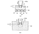
従来、微細粒子のスクリーニング装置は、細胞などの微小物検体を識別、分取するための装置として、医療分野の研究・検査などで広く使用されている。そして近年、研究・検査機関において、検体破壊を伴わない識別、分取を実現すると共に、これらの処理をより正確に行うことで研究・検査の効率を高めたいとの要望がある。特に、所定分野においては、一細胞単位で識別・分取したいとの要望が高まっていることから、このような一細胞単位での識別・分取処理においても、正確性の向上や高効率化が求められている。
図24(a)および(b)は、従来のスクリーニング装置の動作を説明する図である。本図では、最大輝度の蛍光を発している微細粒子M1(目的検体)を含む全ての微細粒子を計測用プレート500のウェル501から吸引して、収容プレート507のウェル508に回収する例を示す。
図24(a)のスクリーニング装置では、制御部503からの指令に基づいて吸引ポンプ504が作動すると、吸引・吐出キャピラリ505が、ウェル500から、最大輝度の蛍光を発している微細粒子Mを含む全数の微細粒子MSを、他のウェル500の微細粒子と区別して選択的に吸引する。その後、吸引・吐出キャピラリ505がZ1方向に上昇、およびZ2方向に下降して、吸引・吐出キャピラリ505の先端部506が、収容プレート507のウェル508の液体A’に入り込み、全数の微細粒子Msをウェル508内に排出する(図24(b))。すなわち、計測用プレート500のX,Y方向への移動操作と、回収部による吸引・吐出キャピラリ505のZ方向の上下移動操作により、計測用プレート500のウェル501から全数の微細粒子MSを回収することができる。この結果、多数の微細粒子から目的検体である微細粒子Mを検知して、選択的に回収することが可能となっている。
しかしながら、上記従来の構成では以下のような問題点がある。すなわち、計測用プレート上に多数のウェルが配置されている場合に、目的検体が収容されたウェルとは異なるウェルから検体を吸引してしまうといった誤作動は防止できるものの、回収条件を満たした微細粒子の入っているウェルにある全ての微細粒子を吸引対象物として選択的に吸引するにとどまり、一細胞単位で目的検体を正確に吸引・回収することは極めて困難である。
また、図24に示すような吸引・吐出キャピラリの先端形状やウェルの形状、あるいはこれらの位置関係では、吸引動作の際、ウェル内の液体に生じる流体抵抗の影響により、目的検体である一細胞を正確に吸引することができない可能性がある。
本発明の目的は、目的検体となる細胞などの微細粒子を、正確に吸引して回収することができるスクリーニング装置およびスクリーニング方法を提供することにある。
上記目的を達成するために、本発明に係るスクリーニング装置は、微細粒子から発する光情報に基づいて所定の微細粒子を探索し、探索された微細粒子を選択的に取得するためのスクリーニング装置であって、光透過性材料で形成され、かつ少なくとも1つの微細粒子を含む液体が収容されるウェルが形成された計測用チップと、前記計測用チップに収容された前記微細粒子に光を照射することにより得られる、前記微細粒子に関する光情報を取得する計測部と、前記光情報を解析して、前記ウェル内に収容されている微細粒子の光情報を抽出する解析部と、前記解析結果に基づいて前記計測用チップから選択的に取得された微細粒子を収容する収容プレートと、前記計測用チップと前記収容プレートとを、前記計測部に対して移動させることが可能な移動部と、ポンプおよび吸引・吐出キャピラリを有し、前記吸引・吐出キャピラリにより前記計測用チップに設けられた前記ウェル内の微細粒子を吸引し、前記収容プレートの所定位置に吐出して回収するための回収部と、を備え、前記吸引・吐出キャピラリの先端外寸が、前記計測用チップに形成された前記ウェルの幅よりも大きく、前記吸引・吐出キャピラリは、前記吸引・吐出キャピラリ先端と前記計測用チップとの間隔が所定距離でありかつ前記吸引・吐出キャピラリ先端の中心軸と前記ウェルの中心軸とがずれた位置にて、前記目的検体である微細粒子を吸引することを特徴とする。
また、スクリーニング装置は、前記計測用チップ上の液体を排出する排出部と、前記計測用チップ上に所定の液体を導入する導入部とを更に備え、前記排出部にて前記計測用チップ上の液体を排出し、前記導入部により所定の液体が導入されることで、前記計測用チップ上の液体を入れ替える。
また、前記計測用チップの上面又はその近傍まで液体が所定量排出された状態で、前記ウェルごとに任意の試薬が滴下されてもよい。
また、前記計測用チップの上面又はその近傍まで液体が所定量排出された状態で、前記計測用チップの所定領域に任意の試薬が噴霧されてもよい。
また、前記計測用チップの上面に、少なくとも1つの仕切部が設けられ、前記排出部および前記注入部の1ユニットが、前記仕切部によって区分けされた2以上の領域ごとに複数設けられてもよい。
また、前記微細粒子は、前記計測用チップ上で保持される前に一の容器に収容され、前記容器内に、前記微細粒子と反応する反応物を、該反応物の濃度を徐々に変化させて複数回に分けて投入し、前記反応物と反応させた微細粒子を含む前記容器内の液体が、前記計測用チップ上に導入されてもよい。
前記計測部は、前記計測用チップに光を照射することにより得られる前記計測用チップに関する光情報に基づいて、前記計測用チップの表面位置を検出し、前記解析部は、前記表面位置と前記微細粒子の大きさから前記微細粒子の中心位置を算出し、前記計測部は、前記中心位置に基づいて、前記ウェルに収容された前記微細粒子の略中心位置に光を照射する。
また、前記ウェルの各々に前記微細粒子が1つずつ収容され、前記解析部は、各ウェルに収容された一の微細粒子からの光情報を解析するのが好ましい。
前記解析部は、各ウェルに収容された少なくとも1つの微細粒子からの光情報を解析して、各ウェル内に収容されている微細粒子の数を特定してもよい。
前記回収部は、前記微細粒子の吸引前に、前記吸引・吐出キャピラリの先端を洗浄するのが好ましい。
好ましくは、前記吸引・吐出キャピラリの端部の少なくとも内面に、疎水化処理面が形成される。
また、前記ポンプは、筒型のポンプ本体と、ポンプ本体内で上下方向に移動可能に設けられたプランジャとを有し、前記ポンプ本体には、前記吸引・吐出キャピラリの管路と連通して設けられ、前記プランジャが移動可能なシリンダと、前記シリンダに設けられた分岐路とを有していてもよい。
さらに、前記分岐路に、管路を介して弁部が接続されており、前記弁部および管路の内径が、前記吸引・吐出キャピラリの内径より大きいのが好ましい。
さらに、前記ポンプの吸引動作後に、前記弁部を開いて前記吸引・吐出キャピラリ内の残圧を解放するのが好ましい。
また、前記微細粒子を吐出する際の前記プランジャの移動量は、前記微細粒子を吸引する際の前記プランジャの移動量より多いのが好ましい。
また、前記吸引・吐出キャピラリは、前記微細粒子を吸引する前に一定量の液体を吸引し、その後、前記微細粒子を吸引するのが好ましい。
また、前記回収部は、前記吸引・吐出キャピラリの先端部と前記計測用チップの上面との接触を検知する検知機構と、前記吸引・吐出キャピラリの先端と前記計測用チップの上面との距離を調整する移動機構とを更に備え、前記吸引・吐出キャピラリが前記計測用チップに接触している場合に、前記吸引・吐出キャピラリの端面と前記計測用チップの上面とが所定距離となる位置に前記吸引・吐出キャピラリを移動することを特徴とする。
また、上記目的を達成するために、本発明に係るスクリーニング装置は、微細粒子から発する光情報に基づいて所定の微細粒子を探索し、探索された微細粒子を選択的に取得するためのスクリーニング装置であって、光透過性材料で形成され、かつ少なくとも1つの微細粒子を含む液体が収容されるウェルが形成された計測用チップと、前記計測用チップに収容された前記微細粒子に光を照射することにより得られる、前記微細粒子に関する光情報を取得する計測部と、前記光情報を解析して、前記ウェル内に収容されている微細粒子の光情報を抽出する解析部と、前記解析結果に基づいて前記計測用チップから選択的に取得された微細粒子を収容する収容プレートと、前記計測用チップと前記収容プレートとを、前記計測部に対して移動させることが可能な移動部と、ポンプおよび吸引・吐出キャピラリを有し、前記吸引・吐出キャピラリにより前記計測用チップに設けられた前記ウェル内の微細粒子を吸引し、前記収容プレートの所定位置に吐出して回収するための回収部と、を備え、前記吸引・吐出キャピラリの先端外寸が、前記計測用チップに形成された前記ウェルの幅よりも大きく、前記吸引・吐出キャピラリの先端面が、前記計測用チップの上面に対して傾いている傾斜面であり、前記吸引・吐出キャピラリは、前記吸引・吐出キャピラリ先端と前記計測用チップとの間隔が所定距離となる位置にて、目的検体である微細粒子を吸引することを特徴とする。
また、上記目的を達成するために、本発明に係るスクリーニング装置は、微細粒子から発する光情報に基づいて所定の微細粒子を探索し、探索された微細粒子を選択的に取得するスクリーニング装置であって、光透過性材料で形成され、かつ少なくとも1つの微細粒子を含む液体が収容されるウェルが形成された計測用チップと、前記計測用チップに収容された前記微細粒子に光を照射することにより得られる、前記微細粒子に関する光情報を取得する計測部と、前記光情報を解析して、前記ウェル内に収容されている微細粒子の光情報を抽出する解析部と、前記解析結果に基づいて前記計測用チップから選択的に取得された微細粒子を収容する収容プレートと、前記計測用チップと前記収容プレートとを、前記計測部に対して移動させることが可能な移動部と、ポンプおよび吸引・吐出キャピラリを有し、前記吸引・吐出キャピラリにより前記計測用チップに設けられた前記ウェル内の微細粒子を吸引し、前記収容プレートの所定位置に吐出して回収するための回収部と、を備え、前記吸引・吐出キャピラリの先端外寸が、前記計測用チップに形成された前記ウェルの幅よりも大きく、前記吸引・吐出キャピラリの先端部における水平方向断面形状が、前記計測用チップにおける前記ウェルの水平方向断面形状と非相似であり、前記吸引・吐出キャピラリは、前記吸引・吐出キャピラリ先端と前記計測用チップとの間隔が所定距離となる位置にて、目的検体である微細粒子を吸引することを特徴とする。
本発明に係るスクリーニング方法は、微細粒子から発する光情報に基づいて所定の微細粒子を探索し、探索された微細粒子を選択的に取得するスクリーニング方法であって、計測用チップ上のウェルの位置座標情報を取得し、前記ウェル内の微細粒子に光を照射して、該微細粒子に関する光情報を取得し、取得された前記位置座標情報および前記光情報に基づいて、所定の回収条件を満たした微細粒子を目的検体として特定し、前記目的検体を吸引・吐出するための吸引・吐出キャピラリの中心位置情報を取得し、取得した前記吸引・吐出キャピラリの中心位置に対して所定距離ずらした位置を、前記ウェルの中心位置として設定し、設定された前記中心位置に合わせて前記ウェルを移動し、前記吸引・吐出キャピラリの先端と前記計測用チップとの間隔が所定距離となる位置にて、前記目的検体である微細粒子を吸引することを特徴とする。
また、上記目的を達成するために、本発明に係るスクリーニング装置は、微細粒子から発する光情報に基づいて所定の微細粒子を探索し、探索された微細粒子を選択的に取得するためのスクリーニング装置であって、光透過性材料で形成され、かつ少なくとも、1つの微細粒子を含む液体が収容されるウェルが形成された計測用チップと、前記計測用チップに収容された前記微細粒子に光を照射することにより得られる、前記微細粒子に関する光情報を取得する計測部と、前記光情報を解析して、前記ウェル内に収容されている微細粒子の光情報を抽出する解析部と、前記解析結果に基づいて前記計測用チップから選択的に取得された微細粒子を収容する収容プレートと、前記計測用チップと前記収容プレートとを、前記計測部に対して移動させることが可能な移動部と、ポンプおよび吸引・吐出キャピラリを有し、前記吸引・吐出キャピラリにより前記計測用チップに設けられた前記ウェル内の微細粒子を吸引し、前記収容プレートの所定位置に吐出して回収するための回収部と、を備え、前記計測用チップ上の液体を排出する排出部と、前記計測用チップ上に所定の液体を導入する導入部とを更に備え、前記排出部にて前記計測用チップ上の液体を排出し、前記導入部により所定の液体が導入されることで、前記計測用チップ上の液体を入れ替えることを特徴とする。
また、前記計測部は、前記微細粒子の蛍光強度の時間変動を前記光情報として取得し、前記解析部は、前記光情報をもとに回収する微細粒子を判定することを特徴とする。
本発明によれば、キャピラリの先端外寸が、計測用チップに形成されたウェルの幅よりも大きく、また、キャピラリは、その先端と計測用チップとの間隔が所定距離でありかつ先端部の中心軸とウェルの中心軸とがずれた位置にて微細粒子を吸引する。これにより、一粒子単位で微細粒子を正確に吸引・回収することができる。また、吸引動作の際、ウェル内に上方に向かう一方向流れを生じさせることができるので、ウェル内の液体に生じる流体抵抗の影響に左右されず、目的検体である微細粒子を正確に吸引することが可能となる。
以下、本発明の実施の形態を図面を参照しながら詳細に説明する。
図1は、第1実施形態に係るスクリーニング装置の構成を概略的に示す側面図であり、図2は、図1のスクリーニング装置の斜視図である。
図1および図2において、スクリーニング装置1は、計測用チップ60内の複数の微細粒子(例えば生体の細胞など)に対して光を照射し、微細粒子から発する蛍光に基づいて目的検体となる所定の微細粒子を探索して、回収条件を満たした微細粒子が収容されたウェル内の微細粒子を選択的に吸引して、収容プレート50に回収する装置である。
具体的には、スクリーニング装置1は、ベース11と、支持部12(図2)と、回収部13と、計測部14と、画像解析部15(解析部)と、移動部16とを備え、図2に示すように、各部がカバー19により覆われている。カバー19は、外部からの光や異物の進入を防いでいる。なお、ベース11は、スクリーニング装置1の各要素を保持するための本体フレームである。
図1に示すように、図1の紙面垂直方向がX方向(第1方向)であり、左右方向がY方向(第2方向)である。Z方向は、X方向とY方向に対して垂直な方向である。
ベース11は、略水平に配されたプレート部材111,112,113を有しており、これらプレート材を介して、回収部13と、計測部14と、移動部16とを保持している。プレート部材111,112は、複数の垂直部材114により平行に固定されており、プレート部材112,113は、複数の部材115により平行に固定されている。この部材114は、振動を遮断する材質からなり、高さ調整可能に構成されている。
上記複数のプレート材のうち最も上に位置するプレート部材113の上には、支持部12と支持台30が固定されている。支持部12は、プレート部材113の上においてZ方向に沿って垂直に立てて配置されている。支持台30は、脚部30aと支持板30bを有している。プレート部材111,112,113と支持板30bは、Z方向に関して相互に所定間隔をおいて配置されている。
支持板30の支持板30b上には、移動部16が載置固定されている。移動部16上には、搭載用テーブル40、収容プレート50および計測用チップ60が搭載されている。移動部16は、搭載用テーブル40、すなわち収容プレート50と計測用チップ60を、X方向および/又はY方向に沿って移動して位置決めすることが可能となっている。
図3は、図2における移動部16と搭載用テーブル40の詳細を示す斜視図である。
図3に示すように、移動部16は、テーブル161と、該テーブル上に配置されたテーブル162を有している。テーブル161は、支持台30に固定されており、テーブル162をX方向に沿って移動して位置決め可能に搭載している。テーブル162は、搭載用テーブル40をY方向に沿って移動して位置決め可能に搭載している。
テーブル161の上面には、ガイドレール163,163とモータ164が設けられている。テーブル162の下面には、断面U字型の係合部材165,165とナット166が設けられている。係合部材165,165は、それぞれガイドレール163,163と移動可能に係合している。モータ164の送りねじ167は、ナット166と螺合している。
また、モータ164は制御部100と電気的に接続されており、制御部100からの指令に応じてモータ164を作動して送りねじ167を回転すると、テーブル162がX方向に沿って移動して位置決めされる。
テーブル162の上面には、ガイドレール168,168とモータ169が設けられている。搭載用テーブル40の下面には、断面U字型の係合部材170,170とナット171が設けられている。係合部材170,170は、それぞれガイドレール168,168と移動可能に係合している。モータ169の送りねじ172は、ナット171と螺合している。
モータ164は制御部100と電気的に接続されており、制御部100からの指令に応じてモータ164を作動して送りねじ172を回転することで、搭載用テーブル40がY方向に沿って移動して位置決めされる。
また、テーブル161は開口部173を、テーブル162は開口部174をそれぞれ有しており、さらに搭載用テーブル40は開口部175を有している。これら開口部173,174,175は、テーブル162がX方向に移動し、搭載用テーブル40がY方向に移動しても常に重なるような大きさを有している。これら開口部173,174,175を介して、計測部14の対物レンズ110側からの光Lが、搭載用テーブル40の上の計測用チップ60の微細粒子に照射される。
また、テーブル162がX方向に移動しかつ搭載用テーブル40がY方向に移動した場合にも、対物レンズ110側からの光Lは、開口部173,174,175を通過して、搭載用テーブル40上の計測用チップ60の微細粒子に照射される。すなわち、テーブル161,162および搭載用テーブル40がいずれの相対位置にあった場合でも、微細粒子から蛍光を発生させることが可能となっている。
図4は、図3の搭載用テーブル40上の収容プレート50と計測用チップ60の構成を示す斜視図である。
搭載用テーブル40は、例えば長方形状の板状部材であり、この搭載用テーブル40の搭載面41の上には収容プレート50と計測用チップ60が着脱可能にY方向に沿って並べて搭載できる。
収容プレート50は、板状の部材であり、収容プレート50には多数のウェル51がX方向とY方向に沿って等間隔でマトリックス状に配列されている。これらのウェル51は、生物細胞等の微細粒子が吸引・吐出キャピラリ140から順次排出されてくるときに順次排出されてくる微細粒子が別々に回収して格納することができる回収格納部である。収容プレート50のウェル51は、例えば鉛直方向断面略U字型の凹部、あるいはカップ型の凹部である。
計測用チップ60は、固定部材120により搭載用テーブル40の搭載面40a上に固定されており、この固定部材120は、搭載用テーブル40の所定位置に位置決めして固定されている。
図5は、計測用チップ60と該計測用チップの固定部材120の構成を示す拡大断面図である。固定部材120は、計測用チップ60を搭載用テーブル40の搭載面41に対して一定の高さの基準面CLの位置で固定して保持する。具体的には、固定部材120は、ケース部121,122および弾性部材123を有している。弾性部材123は例えば略長方形のリング部材であり、弾性部材123はケース部122の内側のフラット面126に固定されている。
計測用チップ60は、ケース部121,122の間に配置されており、計測用チップ60が弾性部材123によりZ1方向に押し上げられることで、計測用チップ60の上面60aは、ケース部121のフラットな内側下面121aに圧接している。また、ケース部121の内側下面121aにはシール部材128が設けられており、シール部材128が固定部材120の基準面CLと計測用チップ60の上面60aの間をシールしている。
そして、計測用チップ60の上面60aがケース部121内側下面121aに押し付けられることで、計測用チップ60の上面60aが基準面CLに位置決めされる。これにより、例えば計測用チップ60の厚みのバラツキや反りがあったとしても、厚みのバラツキの影響や反りの影響による位置決め精度の低下を低減することができる。したがって、計測用チップ60の上面60aと、計測部14の対物レンズ110および収容プレート50とのZ方向に関する距離を正確に管理することが可能である。換言すれば、計測用チップ60のウェル61内の微細粒子Mの位置と、計測部14の対物レンズ110と収容プレート50との距離を正確に管理することができる。
また、ケース部121は、その平面方向中央部かつ計測用チップ60の上方に設けられた、液体Aを保持する液保持部129を有しており、培地、試薬、反応液等の各種液体を保持することが可能に構成されている。なおケース部121は、ケース部122に対して例えば不図示のヒンジ機構部を用いて開閉することができ、これにより、固定部材120内の計測用チップ60を取り出して、新たな計測用チップ60と交換することができる。
計測用チップ60は、光透光性を有する材料、例えばガラスやプラスチックにて成形されており、その上面60aには、多数のウェル61がマトリックス上に配列されている。各ウェル61は、例えば鉛直方向断面略台形、あるいは略カップ型の凹部であり、ウェル61の水平方向断面形状は、好ましくは略円形である。微細粒子Mを分注もしくは一括注入することで、1つの微細粒子Mが格納され得る大きさを有している。
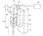
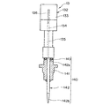
図6は、図1における回収部13の構成を示す斜視図であり、図7は、図6における操作部の構成を示す断面図である。回収部13は、操作部130と基部131を有しており、基部131は支持部12に固定されている。操作部130は、アクチュエータ132(ポンプ)と、吸引・吐出キャピラリ140とを備えている。
アクチュエータ132は、アクチュエータ本体133と、アクチュエータ本体133のシリンダ134に収容された略円筒上のプランジャ136とを有しており、プランジャ136がシリンダ134内を往復運動することで所定流体が圧送される。アクチュエータ132の下方には、アクチュエータ本体133のシリンダ134と吸引・吐出キャピラリ140とを連通する管路135とを有している。
吸引・吐出キャピラリ140は、管路135に着脱可能に取り付けられるフランジ部141と、フランジ部141を貫通して下方に延出するキャピラリ本体142(以下、単に「キャピラリ」という)とを有している。フランジ部141と管路135との接続面には、環状の弾性部材143が取り付けられており、フランジ部141の取付け時に弾性部材143が押圧固定されることで、後述するキャピラリ142の後端部が管路135と密閉接続される。
キャピラリ142は、Z2方向(下方向)に沿って縮径される先細り状の中空部材であり、その内部には管路が形成されている。キャピラリ142の後端部142aは管路135に接続される。キャピラリ142の先端部142bは、微細粒子の吸引時に、計測用チップ60のウェル61に近接する。
基部131は、該基部の上端に配置されたモータ151と、該モータに取り付けられた送りねじ152とを有しており、送りねじ152は、操作部130のナット137と螺合している。モータ151は制御部100と電気的に接続されており、制御部100がモータ151を作動させて送りねじ152を回転することで、ナット137とともに操作部130がZ方向(Z1方向とZ2方向)に沿って上下移動して位置決めされる。
計測部14は、計測用チップ60の複数のウェル61が含まれる領域に対して光Lを照射することで、その領域内の微細粒子Mから蛍光を発生させて、その蛍光を受光する(図1)。受光した微細粒子Mからの蛍光は、画像解析部15により画像解析される。画像解析部15は、各ウェル61内の複数の微細粒子Mの内の、少なくとも最大輝度の蛍光を発する微細粒子M1の蛍光強度を算出する。
X方向とY方向で構成される平面内において、制御部100は、回収条件を満たした最大輝度の蛍光を発する微細粒子M1が収納されているウェル61の位置を検知する。そして制御部100は、図3のモータ164,169に対して制御駆動信号を与えることで、移動部16上の計測用チップ60のウェル61を、吸引・吐出キャピラリ140の真下に位置させることができる。すなわち、吸引・吐出キャピラリ140は、特定のウェルをターゲットとして、当該ウェル内の微細粒子を吸引することが可能に構成されている。また、吸引・吐出キャピラリ140は、複数のウェルの内の選択されたウェル、すなわち所定の回収条件を満たした微細粒子の入っているウェル内から一又は複数の微細粒子を吸引することが可能となっている。さらに、吸引・吐出キャピラリ140は、上記選択された一又は複数の微細粒子を、収容プレート50の所定のウェル51に吐出することが可能となっている。
計測部14は、計測用チップ60および計測用チップ60に収容された微細粒子Mに少なくとも1つ以上の光源より導かれる光を照射することによって、透過光、反射光もしくは蛍光による形状および位置情報、並びに蛍光・化学発光等の輝度情報を個々の微細粒子の平均サイズより細かい分解能で取得すると共に、計測用チップ自体の形状や、計測用チップ60上に配置されたウェル61の位置座標や大きさ等の情報を取得する。
画像解析部15は、計測された形状情報および光情報を解析することで、少なくとも各ウェル61内に、測定者によって設定できる輝度条件を満たす微細粒子M1が存在することを確認するためのデータを取得する。そして、画像解析部15は、透過光もしくは反射光によるウェル61の位置座標情報と蛍光・化学発光の光情報とを合わせ照合することにより微細粒子からの光情報を抽出する。また、計測部14はオートフォーカス機能を有しており、所定位置で合焦した状態で計測を行なうとともに、吸引・吐出キャピラリ140の先端部142bと計測用チップ60上面との位置関係を、両者に対するオートフォーカスの実施により判断することができる。
また、計測部14は、対物レンズ110を有しており、対物レンズ110は計測用チップ60に対して光を導く。対物レンズ110は、計測用チップ60と移動部16の下方に配置されており、吸引・吐出キャピラリ140は、計測用チップ90と移動部16の上方に配置されている。これにより、計測用チップ90とその移動部16は、対物レンズ110と吸引・吐出キャピラリ140の間に配置させることができる。
計測部14では、励起光源181は、例えばレーザ光源や水銀ランプで構成される。シャッターユニット182は、励起光源181と蛍光フィルタユニット183の間に配置されており、シャッターユニット182は計測用チップ60の微細粒子Mに対して光Lを照射しない場合には、励起光源181の発生する光Lを蛍光フィルタユニット183の手前で遮断することが可能となっている。
具体的には、計測部14は、光源としての励起光源181と、励起光源181より照射される光のうち所望の励起波長帯域のみを選択するための光学フィルタ(励起フィルタ)184、計測用チップ60からの光情報の所望の波長帯域のみを選択するための光学フィルタ(蛍光フィルタ)185、および励起光と光情報との波長帯域の差によって光路を切り替えるためのダイクロイックミラー186から構成される蛍光フィルタユニット183と、励起光源181から出射された光を計測用チップ60に導くとともに計測用チップ60から得られる光情報を収集するための対物レンズ110と、対物レンズ110を光軸方向に可動させるオートフォーカス機能を持つフォーカスユニット187と、計測対象からの光情報を検出するための光検出部としての受光部188とを有している。蛍光フィルタユニット183と受光部188は、蛍光落射ユニット190に固定されている。
さらに、計測部14は不図示のハーフミラーを有しており、ハーフミラーと蛍光フィルタユニット183とを切り替えることで、励起光源181からの光の一部を観察対象に照射すると同時に、観察対象からの反射光の一部を受光部188に導くことによって、計測用チップ60の上面60aおよび該上面に形成されたウェル61の形状および位置情報を計測することができる。
この計測部14では、複数の対物レンズ110a,110b・・・が、例えばレボルバー式で回転することで、必要な倍率の対物レンズを計測用チップ60の下方位置に位置決めすることができる。フォーカスユニット187は、例えば制御部100からの指令によりモータ189を作動することで、計測用チップ60の下方位置に配置された例えば対物レンズ110をZ方向に沿って移動して位置決めすることで、計測用チップ60の微細粒子Mに対する対物レンズ110のフォーカス調整を行うことができる。
さて、上記のように構成されるスクリーニング装置1において、本発明者らは、キャピラリ142と計測用チップ60、特に吸引時におけるこれらの位置関係や寸法に着目し、回収部13が計測用チップ60上の微細粒子Mを正確に吸引することができることを見出した。以下、図8および図9を用いて詳細に説明する。
図8は、微細粒子の吸引動作時におけるキャピラリ142とウェル61の位置関係を示す断面図である。
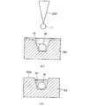
先ず、図8に示すように、キャピラリ142の先端部142bは断面略環形状であり、端面144を有している。このキャピラリ142の先端外寸は、計測用チップ60に形成されたウェル61の幅よりも大きく設計されている。そして、この端面144と計測用チップ60の上面60aとが距離L(L>0)で配置されることで、吸引動作時に、端面144と上面60aとの間にキャピラリ142内に向かう流路が形成されることとなる。また本実施形態では、キャピラリ142の中心軸C1がウェル61の中心軸C2に対してずれるように、キャピラリ142が配置される。換言すれば、キャピラリ142の中心軸C1とウェル61の中心軸C2との距離がδ(δ≠0)となる。このとき、端面144と上面60aとの間には、流路P1と、流路P1より長い流路P2とが形成される。そして、この位置関係にてキャピラリ142が液体Aを吸引すると、流路P1には液体流れF1、流路P2には液体流れF1よりも流量の少ない液体流れF2が生じる。この互いに異なる液体流れF1,F2が生じることにより、ウェル61内には上方に向かう一方向流れF3が生じ、この一方向流れF3によって微細粒子Mがウェル61内から上方に巻き上げられる。この作用によって、キャピラリ142を用いた微細粒子Mの正確な吸引が実現される。
また、上記位置関係において、キャピラリと計測用チップの距離Lと、キャピラリ142、ウェル61および微細粒子Mの寸法とが所定の条件を満たすことで、より正確な吸引動作を実現することが可能となる。例えば本実施形態において、キャピラリ142の先端部142bを略円筒形状とし、先端部142bの外周半径をRo、内周半径をRi、ウェル61の開口半径をRw、微細粒子Mの半径をRcとしたとき、以下に示す(1)~(3)の3つの条件式を満たすように設計される。
2Rc≧L ・・・(1)
Ro-Ri≧0.5L ・・・(2)
Ro-Rw≧0.5L ・・・(3)
また、上記(1)~(3)の条件式を満たす具体的な寸法を表1に示す。
Ro-Ri≧0.5L ・・・(2)
Ro-Rw≧0.5L ・・・(3)
また、上記(1)~(3)の条件式を満たす具体的な寸法を表1に示す。

上記のように、本実施形態では、キャピラリ142とウェル61の距離Lが微細粒子Mの直径(2Rc)よりも小さい(条件式(1))。この条件を満たすことで、隣接する他のウェル61に収容されている微細粒子Mを吸引することがない。また、キャピラリ142の外周半径Roから内周半径Riを引いた値が、距離Lの半分の値より大きく(条件式(2))、さらに、キャピラリ142の外周半径Roからウェル61の開口半径Rwを引いた値が、距離Lの半分の値より大きい(条件式(3))。これら2つの条件を満たすことにより、微細粒子Mを吸引するための一方向流れF3を確実に生じさせることができる。したがって、上記3つの条件式を満たすことで、微細粒子Mのより正確な吸引動作が実現される。
中心軸C1と中心軸C2の距離δは、例えばウェル61の開口半径Rwの0.1倍~1倍程度とするのが好ましい。このように構成すると、上方に向かう一方向流れF3を発生し易くなる。また、距離δは、ウェル61の開口半径Rwの0.2倍~0.4倍程度とするのがより好ましい。これにより、微細粒子Mをキャピラリ142でスムーズに回収することが可能となる。
なお、キャピラリ142の内径と計測用チップのウェル61の外径との関係として、キャピラリの内周半径Riが、ウェル61の開口半径Rwの0.8倍~2倍程度とするのが好ましい。
また、キャピラリ142による吸引動作時には、吸引時における上記位置関係や寸法を規定するのに加えて、微細粒子Mを吸引する前に、液体Aの一定量を吸引するプリ吸引動作を実行するのがより効果的である。このプリ吸引動作を含む吸引制御は、回収部13および制御部100で実行される。
先ず、キャピラリ142の先端部142bを、計測用チップ60上に保持された液体Aに挿入する(図10(a))。そして、先端部142bが、ウェル61内の液体に影響を与えない程度の所定深さまで液体Aに挿入されたときに、所定時間プリ吸引動作を実行する。このとき、液体Aの一定量がキャピラリ142の内部空間Eに進入し、キャピラリ142の先端部142b内で液層A1が形成される(図10(b))。その後、キャピラリ142を上記の距離Lとなる位置まで計測用チップ60に近接させ(図10(c))、所定時間吸引動作を実行すると、液体Aの一定量がキャピラリ142の先端部142b内に進入し、この一定量と共にウェル61内の微細粒子Mが先端部142b内に進入する(図10(d))。これにより、キャピラリ142の先端部142bで液層A2が形成されると共に、目的検体である微細粒子Mがキャピラリ142に吸引される。
また、この吸引制御において、図10(d)に示すように、液層A1の深さd1、液層A1+A2の深さd2とすると、以下の条件式を満たすのが好ましい。
[規則91に基づく訂正 06.09.2013]
d1/d2≧0.1 ・・・(4)
例えば、先端部142bの端面144の内径30μm、テーパ角度10°のキャピラリを使用した場合、微細粒子Mを吸引するまでの吸引総液量を1μlと設定すると、上記d1は0.3mm、d2は2.7mmとなる。よって、プリ吸引動作によって形成される液層A1の液量は0.3μl、その後の吸引動作(微細粒子吸引動作)によって形成される液層A2の液量は0.7μlとなる。
d1/d2≧0.1 ・・・(4)
例えば、先端部142bの端面144の内径30μm、テーパ角度10°のキャピラリを使用した場合、微細粒子Mを吸引するまでの吸引総液量を1μlと設定すると、上記d1は0.3mm、d2は2.7mmとなる。よって、プリ吸引動作によって形成される液層A1の液量は0.3μl、その後の吸引動作(微細粒子吸引動作)によって形成される液層A2の液量は0.7μlとなる。
このような吸引制御を実行すると、キャピラリ142が微細粒子Mの吸引を開始する位置に到達する前に、キャピラリ142内に液層A1が形成されている。よって微細粒子Mが吸引動作開始直後に吸引されたとしても、微細粒子Mがキャピラリ142内で液面に位置せず、微細粒子Mの上方に液層A1が位置することとなる。そして、キャピラリ142の吐出動作時には、液層A1が微細粒子Mを上方から下方に押圧する役割を果たすことで、微細粒子Mがキャピラリ142内に残留することがなく、特に、微細粒子Mがキャピラリ142の内壁に付着して残留するといった現象が防止され、微細粒子Mの吐出精度が向上する。
なお、上記プリ吸引動作において、キャピラリ142は任意の液体が入った別の容器から吸引してもよく、この液体は液体Aと違うものでもよい。液体Aは測定や解析での精度を高めるため、自家蛍光の弱いものを選択して使用することが好ましいが、それが必ずしも微細粒子にとって有利なものとは限らない。例えば収容プレート50にあらかじめ収容されている液体と同じものをプリ吸引することで、液体Aをできるだけ収容プレート50に持ち込まないことができる。
次に、本発明における目的検体のスクリーニング方法を説明する。
図11に示すように、先ず、計測用チップ60の配置情報として、該計測用チップの基準位置の情報や補正パラメータ等を取得し(ステップS1)その後、画像解析を行い、各ウェルの中心位置座標情報を取得する(ステップS2)。次に、光を照射し、微細粒子(サンプル)の光情報を取得して、輝度解析を行う(ステップS3)。輝度解析としては、例えば後述の図12(d)に示すように、各ウェルに反応液を導入して該ウェル内の微細粒子を蛍光させ、この蛍光情報の時間変動を測定してもよい。また、後述の図15に示すように、計測チップ60上の各ウェルに収容されている微細粒子の数を計測してもよい。
次いで、取得された蛍光情報に基づいて、ユーザが所望する微細粒子の回収条件、例えばある蛍光の輝度が所定の閾値を超えたもの、あるいは、複数の蛍光(例えば、蛍光の色が異なる)を使用した場合に、少なくとも一つの蛍光の輝度が所定の閾値を越えたものや、これらの任意の組み合わせを回収条件とする。また、任意の蛍光の輝度につき、回収から除外したもの(閾値より低いもの)を組み合わせてもよく、このようにして決められたいくつかの条件を入力し(ステップS4)、上記回収条件を満たした微細粒子を目的検体として特定する(ステップS5)。そしてキャピラリの中心位置を画像解析等により取得し、その中心位置に対して距離δ分ずらした位置を、微細粒子回収の際のウェルの中心位置(位置情報)として設定する(ステップS6)。そして目的検体が収容された各ウェルの中心位置を、ステップS6で設定された微粒子回収の際のウェルの中心位置に合わせるように移動し、ステップS5で特定された目的検体を順次回収する(ステップS7)。回収されたサンプルは、ユーザが予め設定した収容プレート50上の所定のウェルに収容される。
上述したように、本実施形態によれば、キャピラリ142の先端外寸が、計測用チップ60に形成されたウェル60の幅よりも大きく、また、キャピラリ142は、先端部142bと計測用チップ60との間隔が距離Lでありかつ先端部142の中心軸C1とウェル61の中心軸C2とがずれた位置にて微細粒子Mを吸引する。これにより、細胞単位で微細粒子Mを正確に吸引・回収することができる。また、吸引動作の際、ウェル61内に上方に向かう一方向流れF3を生じさせることができるので、ウェル61内の液体Aに生じる流体抵抗の影響に左右されず、目的検体である微細粒子Mを正確に吸引することが可能となる。また上記構成によれば、目的検体である一の微細粒子Mを正確に吸引・回収することが可能となり、一細胞単位で処理を実行することができる。
次に、第2実施形態に係るスクリーニング装置を説明する。本実施形態のスクリーニング装置は、第1実施形態のスクリーニング装置に、液保持部に液を注入、あるいは液保持部から液体を排出する機構を付加したものである。なお、本第2実施形態は、第1実施形態に係るスクリーニング装置の構成を必ずしも備える必要はなく、第1実施形態の構成によらず、単独でも実施することが可能である。
このスクリーニング装置において、図12(a)に示すように、ケース部221は、その平面方向中央部かつ計測用チップ60の上方に設けられた、液体Aを保持する液保持部229を有しており、培地、試薬、反応液等の各種液体を保持することが可能に構成されている。この液保持部229は、ケース部221の内側側面221aと計測用チップ60の上面60aとで確定される空間である。
そして本実施形態では、液保持部229の一端側上方近傍に液導入部230が設けられ、多端側上方近傍に液排出部231が設けられている。液導入部230は、液保持部229に所定液体を導入し、液排出部231は、液保持部229に保持されていた所定液体を排出する。また、この液導入部230と液排出部231は、排出・導入動作を同時に実行することができるように構成されている。例えば、液保持部229に培地Gが保持されている場合に、液排出部231にて培地Gを外部に排出しながら液導入部230にて反応液Hを液保持部229に導入する。これにより、液保持部229に保持されていた培地Gが反応液Hに入れ替わる。また、本方法にて微細粒子Mを反応させ、微細粒子Mからの蛍光を測定すると、反応しない微細粒子と比較して強い輝度が得られることが分かる(図12(d))。
なお、液導入部230の代わりに、培地Gの液面位置が計測用チップ上面又はその近傍となるまで培地Gを所定量外部に排出した状態で、ウェルごとに試薬等の液体を液滴I1として滴下する滴下部232を設けてもよく(図12(b))、あるいは、計測用チップ上面まで培地Gを所定量外部に排出した状態で、試薬等の液体を、複数のウェルを含む所定領域に対してミストI2として噴霧する噴霧部233を設けてもよい(図12(c))。また、噴霧部233を図12に示すように配置した場合、ケース部221に近いウェルではミストI2のミスト量が多く、ケース部221から離れるにしたがってミストI2のミスト量が少なくなる。このように、計測用チップ60に対する噴霧部233の取付け位置を変更することで、各ウェルに導入されるミストI2の濃度を異ならせることが可能である。
また、図12(a)に示した実施形態において、反応液導入後、計測用チップの各ウェル内にある微細粒子の蛍光強度の時間変動が図12(d)のように測定されることを用い、画像解析部15は該時間変動を連続的に測定し、その測定結果に基づいて、サンプル回収をするウェルを特定してもよい。例えば、蛍光強度の時間変動データにおいて、そのピーク値と後述するベース値との差分値を、任意の閾値と比較してピーク値が閾値を超えたサンプルを回収対象と判断したり、逆にピーク値が閾値を超えたサンプルを回収対象から除外することにより、微細粒子の反応の有無を選択して回収することができる。
ここで、ベース値は、例えば(i)測定中の最小値、(ii)指定した測定時間までの平均(すなわち、液体導入前の値の平均値)、(iii)ある反応液を導入したときの値の平均(例えば、反応しないはずの液体を流したときの値の平均値)、(iv)ゼロ(この場合、ピークのみを扱う)によって定められる。また、ピークについてはノイズと区別するために移動平均をとることができ、有意差を判断するために標準偏差σをもとに、指定した基準以下の差分を排除してもよい。
ここで、液排出部231によって培地Gを排出できる限界位置は計測用チップ60の上面60aであり、実際にはごく僅かに培地Gが残る。この状態でも、図13(a)に示すように、微細粒子M(細胞)が存在するウェル61の中心に向けて試薬等の液体を液滴I1として滴下することで、微細粒子M付近はほぼ目的の試薬で満たされるため、当該微細粒子を反応させることができる。
また隣接ウェルとの混合を避けたい場合は、図13(b)に示すように、液体の排出後に計測用チップ60を乾燥させ、ウェル61内に入れられた液体の水面を計測用チップ60の上面60aより低い状態とすることで、各ウェルを完全に分離して反応させることもできる。
なお、図12(b)および図12(c)では、スクリーニング装置1に滴下部232や噴霧部233が設けられるが、これに限らず、スクリーニング装置1に滴下部や噴霧部を設けることなく、装置外部にて滴下処理や噴霧処理が施されてもよい。
上記液保持部229の変形例として、図14に示すように、液保持部229の平面領域を5つの領域234a~234eに区切る仕切部235が設けられてもよい。このように複数の領域に分けると、領域ごとに任意の種類の液体を導入して、微細粒子を反応させることが可能となる。なお、仕切部235を使用する場合、液導入部/液排出部は領域ごとに設けられてもよいし、複数の領域のうちの一部に設けられてもよい。
また、本実施形態では、先ずウェル61内に1つの微細粒子Mを収容させ、その後にウェルに液体を導入して微細粒子Mを反応させる方法を採用している。この方法とは逆に、先に微細粒子Mを反応させ、その後にウェル61内に1つの微細粒子Mを収容させることも可能である。
具体的には、図15(a)に示すように、先ず、微細粒子Mとしての細胞mを多量に含有した液を容器240に入れ、その後、抗体、化合物等の被反応物kを含有する高濃度の液体K1を容器240に投入して一定時間反応を待つ。このとき、幾つかの細胞mは被反応物kと反応して反応細胞m1となる(図15(a)では2つの細胞が反応)。次に、容器240内での被反応物kの濃度を薄めるべく、一定量の培地などの液体K2を容器240に投入して再度一定時間反応を待つ。すると、最初の高濃度では反応しなかった所定細胞mが反応して反応細胞m1となる(図15(a)では、新たに1つの細胞が反応)。以後、液体K2を投入する作業を繰り返して、被反応物kの濃度を徐々に薄めていき、各濃度で所定細胞mを反応させる(図15(a)では、最終的に6つの細胞mが反応)。
その後、容器240内の液体を液保持部229に導入して、各細胞をウェル61内に収容する。そして、吸引・吐出キャピラリ140のキャピラリ140にて反応細胞m1を一細胞単位で吸引・回収し、回収した反応細胞m1を培養・分析する。本方法によれば、一細胞の単位での吸引・回収を実現すると共に、細胞の反応特性に因らずに検出精度を向上することができる。
また、上記方法とは反対に、容器240内の被反応物kの濃度を徐々に高くしていってもよい。さらに、反応に使用される試薬は1種類に限らず、複数の試薬でもよい。反応させる細胞は、1種類に限らず、複数種類であってもよい。
次に、計測部14の変形例を説明する。
上述のように、計測部14は、透過光、反射光もしくは蛍光による微細粒子の位置情報を一細胞単位で取得するが、希に1つのウェルに複数の微細粒子が収容される場合がある。また、1つのウェルに1つの微細粒子が収容されていても、微細粒子の大きさにばらつきがあるため、目的検体がよりウェルのサイズに対して小さい微細粒子である場合、微細粒子がウェルの深さ方向のいずれの位置にあるか不明であり、正確に測定できない場合がある。
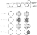
そこで、図16に示すように、計測部14は、計測用チップ60に光を照射することにより得られる該計測用チップに関する光情報に基づいて、計測用チップ60の表面位置を検出する。そして、計測部14は、目的検体である微細粒子Mの粒径およびウェルの寸法に基づいて、微細粒子Mに照射される光の焦点位置を深さ方向(計測用チップ60の厚さ方向)に所定量補正する(3D計測)。具体的には、画像解析部15は、計測用チップ60の表面位置と微細粒子Mの大きさから該微細粒子の中心位置を算出する。そして計測部14は、上記中心位置に基づいて、ウェル61に収容された微細粒子Mの略中心位置に光を照射する。例えば、微細粒子Mの外径が約20μm、ウエル外径が30μm、ウェルの深さが約25μmである場合、照射光の焦点を、計測用チップ60の上面60aを基準表面位置(±0)として、基準表面位置から微粒子の半径程度を目安として-10μmの位置に変更する。
このように、ウェルの深さは、ウェル外径の5割~10割程度、より好ましくは7割~8割程度とすることによって、1つのウェルに1つの微粒子を好適に収容し、回収することができる。また、微粒子の外径は、ウェル外径に対し、5割~8割程度とするのが好ましい。
上記焦点変更制御によれば、透過光によって、ウェル61内の微細粒子Mの数を解析・特定することが可能となり、また、一粒子単位での回収精度を向上することもできる。また、蛍光によって、微細粒子Mの中で最も高い蛍光輝度を計測することができるので、解析結果を向上させることできる。
特に、微細粒子Mは、ウェル61内の底部に配置されることが多く、計測用チップ表面にフォーカスした状態(0μm)では、十分な蛍光輝度が得られず、正確な測定が行われないことがある。そこで本発明では、ウェル61の形状と微細粒子Mの大きさから微細粒子の中心の位置を算出し、算出した位置にフォーカスすることで精度の高い測定結果を得ることができる。例えば、ウェル61と微細粒子Mの大きさの関係が図16に示すような場合、(b)に示す-10μmの位置にフォーカスすることで最も精度の高い測定結果を得ることができる。
更に、微細粒子の半径と同程度、例えば図16ならば10μm間隔で、ウェルの底部から計測チップ表面部をカバーするように、+10μm~-20μmの間でフォーカス位置を変更して情報を得るのが好ましい。例えば、図16の一番右のウェルにおいて、(b)に示す-10μmの位置と、(d)に示す+10μmの位置の双方で強い蛍光情報が得られた場合、微細粒子が2つ存在すると判定する。本方法によれば、1つのウェル内に存在する微細粒子の数を計測することができる。
また、本実施形態において、キャピラリ142の先端部142bには、上記のように、微細粒子Mの吸引・吐出時に、各種液体や微細粒子Mが付着する可能性があるため、微細粒子Mの吸引前に、キャピラリ142の先端部142bを洗浄するのが好ましい。なお、本洗浄では、収容プレート50内のウェル51を洗浄槽として使用してもよいし、ウェルとは別に設けられた洗浄槽を使用してもいい。
例えば、図17(a)に示すように,吸引・吐出動作を行うと、先端部142bの内壁251や外壁253には、微細粒子Mが付着している場合がある。よって、キャピラリ142の先端部142bを、洗浄槽Xに入れられた洗浄液Yに挿入することで(図17(b))、キャピラリ142の外壁253に付着した微細粒子を除去することができる。また、洗浄液を吸引・吐出することで(図17(c))、キャピラリ142の内壁251に付着した微細粒子を除去することができる。
また、図18(a)および(b)に示すように、吸引動作時における液体の深さをδ1(図10(d)の深さd2に対応)、吐出動作時に収容プレート50の液面に挿入されるキャピラリ142の深さをδ2とする。このとき、洗浄槽内の液面に挿入するキャピラリ142の深さδw2は、吐出動作時の深さδ2よりも大きく設定することが好ましい(δw2>δ2)。このように設定することで、キャピラリ142の外壁253が十分に洗浄される。また、洗浄してもなお外壁253に微細粒子Mが残留している場合であっても、当該微細粒子はキャピラリ142の外壁253の上方に残留するため、収容プレート50への吐出動作の際に目的外の微細粒子が収容プレート50に落ちるのを防止することができる。
また、洗浄液の吸引量δw1は、吸引動作時における液体の深さδ1よりも大きく設定することが好ましい(δw1>δ1)。このように設定することで、吐出されずにキャピラリ142の内壁251に微細粒子Mが残留した場合に、十分な洗浄液の吸引により吐き出される可能性が高くなる。また、本洗浄を行ってもなお内壁251に微細粒子Mが残留している場合であっても、当該微細粒子はキャピラリ142の内壁251の上方に残留するため、次の吸引動作の際に残留微細粒子が悪影響を与えることはない。
図19(a)~(c)は、キャピラリ142の先端部142bの変形例を示す図である。
図19(a)に示すように、先端部142の内壁251に疎水化処理層252(疎水化処理面)が、外壁253に疎水化処理層254が設けられるのが好ましい。この疎水化処理層252,254は、例えばシリコーンを主成分とする材料をコーティングすることで形成される。本疎水化処理層の形成により、微細粒子Mの回収時に、各種液体が先端部142bに残留しにくくなり、各種液体を収容プレート50に持ち込むのを防止することができる。
一方、先端部142bの内壁251、外壁253に、それぞれ親水化処理膜255,256が設けられてもよい(図19(b))。親水化処理膜255,256は、例えばプラズマ処理による親水コーティングにより形成される。本親水化処理膜により、細胞等の微細粒子Mが内壁251、外壁253に付着しにくくなり、微細粒子Mの吐出精度を向上することができる。
また、先端部142bの内壁251の先端側に親水処理膜257を設け、親水処理膜257の上方に疎水処理層258を設けてもよい。本構成によれば、キャピラリ142内部の先端側が親水処理され、奥側が疎水処理されているため、吸引時に微細粒子Mがキャピラリ142の奥側に進行しにくく、吐出時には微細粒子Mがキャピラリ142に残りにくくなる。よって、吸引・吐出精度を向上することが可能になる。
次に、回収部13の変形例を、図20および図21を用いて説明する。本変形例の回収部は、今回の吸引動作時におけるキャピラリ142内の残圧を開放して、次回の吸引動作時の回収精度を向上させるための機構である。なお、本変形例の構成は回収部13と基本的に同じであるので、以下に異なる部分を説明する。
図20に示すように、回収部330は、アクチュエータ本体133のシリンダ331に設けられた分岐路332と、分岐路332に接続され、ゴムチューブ等の弾性材料で構成される管路333と、該管路に接続された電磁弁334(弁部)と、電磁弁334の開口側に設置された防塵フィルタ335とを有している。また、管路331の内径はキャピラリ142の端面144における内径よりも大きく、電磁弁334内の流路内径も、キャピラリ142の端面144における内径よりも大きい。
この回収部330の動作は、図21(a)に示すように、先ず、プランジャ136が上方に移動することで、キャピラリ142にて目的検体である微細粒子Mを含む液体が吸引される。このとき、電磁弁334は閉じているため、分岐路332での空気流れは生じていない。
次に、プランジャ136が上方に移動して、キャピラリ142から目的検体Mを含む液体を吐出する(図21(b))。このとき、プランジャ136は、上記吸引動作時に移動した移動量よりも多い移動量で動作する。本動作により、キャピラリ142内の微細粒子Mあるいは液体の全部が押し出される。この吐出動作時も、電磁弁334は閉じているため、分岐路332での空気流れは生じない。
その後、プランジャ136を吸引動作前の位置に戻す際には、先ず電磁弁334が開き、電磁弁334が開いた状態でプランジャ136が上方に移動する(図21(c))。このとき、防塵フィルタ335は開放端であり、また、管路331の内径および電磁弁334内の流路内径がキャピラリ142の端面144における内径よりも大きいため、分岐路332に内方への空気流れが生じ、これによりキャピラリ142内の残圧が開放される。
よって、本変形例によれば、吐出動作時にキャピラリ142内の微細粒子Mあるいは液体の全部が押し出され、また、再度の吸引動作前に、キャピラリ142内の残圧が開放されるので、回収精度をさらに向上することが可能となる。
なお本変形例では、残圧開放を自然吸気で行っているが、電磁弁334にポンプ336を配置し、プランジャ136を吸引動作前の位置に戻す際に、強制的に分岐路332に空気を送り込んでもよい(図20)。これにより、さらに回収精度を向上することができる。
図22および図23は、キャピラリ142の先端形状の変形例を示す図である。
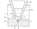
図8で示したように、キャピラリ142の一方側と他方側で流量の異なる液体流れF1,F2を発生させればよいことから、キャピラリ142の先端部142bの形状を以下のようにすることも可能である。例えば、図22の変形例では、キャピラリ342の先端部342bは、水平方向に対して所定角度α(0°<α<90°)となる端面344を有している。すなわち、端面344は、計測用チップ60の上面60aと平行でなく、上面60aに対して傾いている傾斜面となることから、互いに流量の異なる液体流れF1,F2を発生させることができ、ウェル61内に、上方に向かう一方向流れF3を発生させることができる。
また、図23(a)~(c)の変形例では、キャピラリ442の先端部442bは、螺旋形状の端面444と、段差部445とを有している。端面444は、計測用チップ60の上面60aに対して傾いている傾斜面であり、該傾斜面に段差部445が形成されている。この段差部445により、端面444の近傍に螺旋状の渦が発生し、流量が大きく異なる液体流れF1,F2を発生させることができる。よって、ウェル61内に、上方に向かう一方向流れF3を確実に発生させることができ、微細粒子Mの正確な吸引を実現できる。
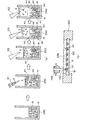
図24は、図7における回収部13の変形例を示す斜視図であり、図25(a)~(d)は、図24の回収部の動作を説明する図である。本変形例における回収部は、図7の回収部130の構成に加えて、後述する検知部および上下移動ステージを有している。なお、回収部130と同一の構成については同一の番号を付し、その説明を省略する。
図24に示すように、回収部450は、アクチュエータ132の上部に配置され、吸引・吐出キャピラリ140に加えられる負荷を検知する検知部451(検知機構)と、吸引・吐出キャピラリ140を上下方向に移動する上下移動ステージ452(移動機構)とを備えている。検知部451は、例えば圧力センサであり、吸引・吐出キャピラリ140が計測用チップ60に加える圧力を検知する。制御部100は、上記圧力センサからの信号に基づいて、キャピラリ142の先端部142bと計測用チップ60の上面60aとが接触しているか否かを判定し、当該判定結果に応じた信号を上下移動ステージ452に送信する。上下移動ステージ452は、制御部100からの信号に応じて、不図示のモータの駆動により、吸引・吐出キャピラリ140を上下方向に移動する。
本変形例の回収部450は、以下の様に動作する。すなわち、図25(a)~(d)に示すように、制御部100は、検知部451からの信号を受信し、吸引・吐出キャピラリ142の端面144が計測用チップ60の上面60aに接触しているか否かを判定する。検知部451が検出した圧力が0であれば、制御部100は、端面144が上面60aに接触してないと判断し、微細粒子Mの吸引動作を行う(図25(b))。一方、検知部451が検出した圧力が0より大きい場合、制御部100は、吸引・吐出キャピラリ142の端面144と計測用チップ60の上面60aとが接触していると判断し(図25(c))、上下移動ステージ452を上方に移動させ、吸引・吐出キャピラリ140を所定距離だけ上昇させる(図25(d))。その後、調整後の位置にて微細粒子Mの吸引動作を行う。
ここで、目的検体である微細粒子のみを吸引するには、吸引・吐出キャピラリ直下の微細粒子Mを確実に吸引し、かつ周囲の微細粒子を吸引しない必要がある。上述のように、理想的には、吸引・吐出キャピラリ140の端面144と計測用チップ60の上面60aとの距離Lが小さい程、目的の微細粒子Mのみを正確に吸引することができる。一方、相対的な移動誤差や、計測用チップ60のうねり、あるいは解析誤差により、吸引・吐出キャピラリ142の端面144と計測用チップ60の上面60aとの距離Lが狙いよりもずれてしまう場合がある。このとき、距離Lが0になると、吸引・吐出キャピラリ142が計測用チップ60に接触してしまい、真空状態になるために吸引できなくなることがある。
本変形例によれば、吸引・吐出キャピラリ142と計測用チップ60に接触している場合にはこれらを離間させるので、吸引・吐出キャピラリ142で微細粒子Mを吸引できなくなるのを確実に防止することができる。また、吸引できない状態を確実に回避できることから、吸引・吐出キャピラリ142の端面144と計測用チップ60の上面60aの距離Lをできる限り小さく設定することができ、目的検体である微細粒子Mのみを確実に吸引することができる。
なお本実施形態では、キャピラリ142の先端部142bは略円筒形状であるが、略角筒形状であってもよい。またウェル61の水平方向断面形状は略円形であるが、略矩形であってもよい。また、キャピラリ先端部の水平方向断面形状が、ウェルの水平方向断面形状と非相似であってもよく、また、異形であってもよい。例えば、キャピラリ先端部の水平方向断面形状が略円形であり、ウェルの水平方向断面形状が略矩形であってもよい。本構成によっても、上記同様の効果を奏することができる。
以上、本発明者によってなされた発明を実施形態に基づいて具体的に説明したが、本発明は上記実施形態に限定されるものではなく、その要旨を逸脱しない範囲で変更可能である。
1 スクリーニング装置
11 ベース
12 支持部
13 回収部
14 計測部
15 画像解析部
16 移動部
19 カバー
40 搭載用テーブル
50 収容プレート
51 ウェル
60 計測用チップ
60a 上面
61 ウェル
140 吸引・吐出キャピラリ
141 フランジ部
142 キャピラリ
142b 先端部
144 端面
11 ベース
12 支持部
13 回収部
14 計測部
15 画像解析部
16 移動部
19 カバー
40 搭載用テーブル
50 収容プレート
51 ウェル
60 計測用チップ
60a 上面
61 ウェル
140 吸引・吐出キャピラリ
141 フランジ部
142 キャピラリ
142b 先端部
144 端面
Claims (22)
- 微細粒子から発する光情報に基づいて所定の微細粒子を探索し、探索された微細粒子を選択的に取得するためのスクリーニング装置であって、
光透過性材料で形成され、かつ少なくとも1つの微細粒子を含む液体が収容されるウェルが形成された計測用チップと、
前記計測用チップに収容された前記微細粒子に光を照射することにより得られる、前記微細粒子に関する光情報を取得する計測部と、
前記光情報を解析して、前記ウェル内に収容されている微細粒子の光情報を抽出する解析部と、
前記解析結果に基づいて前記計測用チップから選択的に取得された微細粒子を収容する収容プレートと、
前記計測用チップと前記収容プレートとを、前記計測部に対して移動させることが可能な移動部と、
ポンプおよび吸引・吐出キャピラリを有し、前記吸引・吐出キャピラリにより前記計測用チップに設けられた前記ウェル内の微細粒子を吸引し、前記収容プレートの所定位置に吐出して回収するための回収部と、を備え、
前記吸引・吐出キャピラリの先端外寸が、前記計測用チップに形成された前記ウェルの幅よりも大きく、
前記吸引・吐出キャピラリは、前記吸引・吐出キャピラリ先端と前記計測用チップとの間隔が所定距離でありかつ前記吸引・吐出キャピラリ先端の中心軸と前記ウェルの中心軸とがずれた位置にて、目的検体である微細粒子を吸引することを特徴とするスクリーニング装置。 - 前記計測用チップ上の液体を排出する排出部と、前記計測用チップ上に所定の液体を導入する導入部とを更に備え、
前記排出部にて前記計測用チップ上の液体を排出し、前記導入部により所定の液体が導入されることで、前記計測用チップ上の液体を入れ替えることを特徴とする、請求項1記載のスクリーニング装置。 - 前記計測用チップの上面又はその近傍まで液体が所定量排出された状態で、前記ウェルごとに任意の試薬が滴下されることを特徴とする、請求項1記載のスクリーニング装置。
- 前記計測用チップの上面又はその近傍まで液体が所定量排出された状態で、前記計測用チップの所定領域に任意の試薬が噴霧されることを特徴とする、請求項1記載のスクリーニング装置。
- 前記計測用チップの上面に、少なくとも1つの仕切部が設けられ、
前記排出部および前記注入部の1ユニットが、前記仕切部によって区分けされた2以上の領域ごとに複数設けられることを特徴とする、請求項2記載のスクリーニング装置。 - 前記微細粒子は、前記計測用チップ上で保持される前に一の容器に収容され、
前記容器内に、前記微細粒子と反応する反応物を、該反応物の濃度を徐々に変化させて複数回に分けて投入し、
前記反応物と反応させた微細粒子を含む前記容器内の液体が、前記計測用チップ上に導入されることを特徴とする、請求項1記載のスクリーニング装置。 - 前記計測部は、前記計測用チップに光を照射することにより得られる前記計測用チップに関する光情報に基づいて、前記計測用チップの表面位置を検出し、
前記解析部は、前記表面位置と前記微細粒子の大きさから前記微細粒子の中心位置を算出し、
前記計測部は、前記中心位置に基づいて、前記ウェルに収容された前記微細粒子の略中心位置に光を照射することを特徴とする、請求項1記載のスクリーニング装置。 - 前記ウェルの各々に前記微細粒子が1つずつ収容され、
前記解析部は、各ウェルに収容された一の微細粒子からの光情報を解析することを特徴とする、請求項1乃至7のいずれか1項に記載のスクリーニング装置。 - 前記解析部は、各ウェルに収容された少なくとも1つの微細粒子からの光情報を解析して、各ウェル内に収容されている微細粒子の数を特定することを特徴とする、請求項1乃至7のいずれか1項に記載のスクリーニング装置。
- 前記回収部は、前記微細粒子の吸引前に、前記吸引・吐出キャピラリの先端を洗浄することを特徴とする、請求項1記載のスクリーニング装置。
- 前記吸引・吐出キャピラリの端部の少なくとも内面に、疎水化処理面が形成されることを特徴とする、請求項1記載のスクリーニング装置。
- 前記ポンプは、筒型のポンプ本体と、ポンプ本体内で上下方向に移動可能に設けられたプランジャとを有し、
前記ポンプ本体には、前記吸引・吐出キャピラリの管路と連通して設けられ、前記プランジャが移動可能なシリンダと、前記シリンダに設けられた分岐路とを有することを特徴とする、請求項1記載のスクリーニング装置。 - 前記分岐路に、管路を介して弁部が接続されており、
前記弁部および管路の内径が、前記吸引・吐出キャピラリの内径より大きいことを特徴とする、請求項12記載のスクリーニング装置。 - 前記ポンプの吸引動作後に、前記弁部を開いて前記吸引・吐出キャピラリ内の残圧を解放することを特徴とする、請求項13記載のスクリーニング装置。
- 前記微細粒子を吐出する際の前記プランジャの移動量は、前記微細粒子を吸引する際の前記プランジャの移動量より多いことを特徴とする、請求項14記載のスクリーニング装置。
- 前記吸引・吐出キャピラリは、前記微細粒子を吸引する前に一定量の液体を吸引し、その後、前記微細粒子を吸引することを特徴とする、請求項1記載のスクリーニング装置。
- 前記回収部は、前記吸引・吐出キャピラリの先端と前記計測用チップの上面との接触を検知する検知機構と、前記吸引・吐出キャピラリの先端と前記計測用チップの上面との距離を調整する移動機構とを更に備え、
前記吸引・吐出キャピラリが前記計測用チップに接触している場合に、前記吸引・吐出キャピラリの端面と前記計測用チップの上面とが所定距離となる位置に前記吸引・吐出キャピラリを移動することを特徴とする、請求項1記載のスクリーニング装置。 - 微細粒子から発する光情報に基づいて所定の微細粒子を探索し、探索された微細粒子を選択的に取得するためのスクリーニング装置であって、
光透過性材料で形成され、かつ少なくとも1つの微細粒子を含む液体が収容されるウェルが形成された計測用チップと、
前記計測用チップに収容された前記微細粒子に光を照射することにより得られる、前記微細粒子に関する光情報を取得する計測部と、
前記光情報を解析して、前記ウェル内に収容されている微細粒子の光情報を抽出する解析部と、
前記解析結果に基づいて前記計測用チップから選択的に取得された微細粒子を収容する収容プレートと、
前記計測用チップと前記収容プレートとを、前記計測部に対して移動させることが可能な移動部と、
ポンプおよび吸引・吐出キャピラリを有し、前記吸引・吐出キャピラリにより前記計測用チップに設けられた前記ウェル内の微細粒子を吸引し、前記収容プレートの所定位置に吐出して回収するための回収部と、を備え、
前記吸引・吐出キャピラリの先端外寸が、前記計測用チップに形成された前記ウェルの幅よりも大きく、
前記吸引・吐出キャピラリの先端面が、前記計測用チップの上面に対して傾いている傾斜面であり、
前記吸引・吐出キャピラリは、前記吸引・吐出キャピラリ先端と前記計測用チップとの間隔が所定距離となる位置にて、目的検体である微細粒子を吸引することを特徴とするスクリーニング装置。 - 微細粒子から発する光情報に基づいて所定の微細粒子を探索し、探索された微細粒子を選択的に取得するスクリーニング装置であって、
光透過性材料で形成され、かつ少なくとも1つの微細粒子を含む液体が収容されるウェルが形成された計測用チップと、
前記計測用チップに収容された前記微細粒子に光を照射することにより得られる、前記微細粒子に関する光情報を取得する計測部と、
前記光情報を解析して、前記ウェル内に収容されている微細粒子の光情報を抽出する解析部と、
前記解析結果に基づいて前記計測用チップから選択的に取得された微細粒子を収容する収容プレートと、
前記計測用チップと前記収容プレートとを、前記計測部に対して移動させることが可能な移動部と、
ポンプおよび吸引・吐出キャピラリを有し、前記吸引・吐出キャピラリにより前記計測用チップに設けられた前記ウェル内の微細粒子を吸引し、前記収容プレートの所定位置に吐出して回収するための回収部と、を備え、
前記吸引・吐出キャピラリの先端外寸が、前記計測用チップに形成された前記ウェルの幅よりも大きく、
前記吸引・吐出キャピラリの先端部における水平方向断面形状が、前記計測用チップにおける前記ウェルの水平方向断面形状と非相似であり、
前記吸引・吐出キャピラリは、前記吸引・吐出キャピラリ先端と前記計測用チップとの間隔が所定距離となる位置にて、目的検体である微細粒子を吸引することを特徴とするスクリーニング装置。 - 微細粒子から発する光情報に基づいて所定の微細粒子を探索し、探索された微細粒子を選択的に取得するスクリーニング方法であって、
計測用チップ上のウェルの位置座標情報を取得し、
前記ウェル内の微細粒子に光を照射して、該微細粒子に関する光情報を取得し、
取得された前記位置座標情報および前記光情報に基づいて、所定の回収条件を満たした微細粒子を目的検体として特定し、
前記目的検体を吸引・吐出するための吸引・吐出キャピラリの中心位置情報を取得し、
取得した前記吸引・吐出キャピラリの中心位置に対して所定距離ずらした位置を、前記ウェルの中心位置として設定し、
設定された前記中心位置に合わせて前記ウェルを移動し、前記吸引・吐出キャピラリの先端と前記計測用チップとの間隔が所定距離となる位置にて、前記目的検体である微細粒子を吸引することを特徴とする、スクリーニング方法。 - 微細粒子から発する光情報に基づいて所定の微細粒子を探索し、探索された微細粒子を選択的に取得するためのスクリーニング装置であって、
光透過性材料で形成され、かつ少なくとも1つの微細粒子を含む液体が収容されるウェルが形成された計測用チップと、
前記計測用チップに収容された前記微細粒子に光を照射することにより得られる、前記微細粒子に関する光情報を取得する計測部と、
前記光情報を解析して、前記ウェル内に収容されている微細粒子の光情報を抽出する解析部と、
前記解析結果に基づいて前記計測用チップから選択的に取得された微細粒子を収容する収容プレートと、
前記計測用チップと前記収容プレートとを、前記計測部に対して移動させることが可能な移動部と、
ポンプおよび吸引・吐出キャピラリを有し、前記吸引・吐出キャピラリにより前記計測用チップに設けられた前記ウェル内の微細粒子を吸引し、前記収容プレートの所定位置に吐出して回収するための回収部と、を備え、
前記計測用チップ上の液体を排出する排出部と、前記計測用チップ上に所定の液体を導入する導入部とを更に備え、
前記排出部にて前記計測用チップ上の液体を排出し、前記導入部により所定の液体が導入されることで、前記計測用チップ上の液体を入れ替えることを特徴とする、スクリーニング装置。 - 前記計測部は、前記微細粒子の蛍光強度の時間変動を前記光情報として取得し、前記解析部は、前記光情報に基づいて回収する微細粒子を判定することを特徴とする、請求項21記載のスクリーニング装置。
Priority Applications (4)
| Application Number | Priority Date | Filing Date | Title |
|---|---|---|---|
| JP2013553179A JP5625125B2 (ja) | 2012-10-09 | 2013-06-14 | スクリーニング装置およびスクリーニング方法 |
| EP13845401.2A EP2908116A4 (en) | 2012-10-09 | 2013-06-14 | SCREENING DEVICE AND SCREENING METHOD |
| CN201380045162.0A CN104603597B (zh) | 2012-10-09 | 2013-06-14 | 筛选装置以及筛选方法 |
| US14/667,465 US10101276B2 (en) | 2012-10-09 | 2015-03-24 | Screening apparatus and screening method |
Applications Claiming Priority (2)
| Application Number | Priority Date | Filing Date | Title |
|---|---|---|---|
| JP2012-224512 | 2012-10-09 | ||
| JP2012224512 | 2012-10-09 |
Related Child Applications (1)
| Application Number | Title | Priority Date | Filing Date |
|---|---|---|---|
| US14/667,465 Continuation US10101276B2 (en) | 2012-10-09 | 2015-03-24 | Screening apparatus and screening method |
Publications (1)
| Publication Number | Publication Date |
|---|---|
| WO2014057713A1 true WO2014057713A1 (ja) | 2014-04-17 |
Family
ID=50477190
Family Applications (1)
| Application Number | Title | Priority Date | Filing Date |
|---|---|---|---|
| PCT/JP2013/066442 Ceased WO2014057713A1 (ja) | 2012-10-09 | 2013-06-14 | スクリーニング装置およびスクリーニング方法 |
Country Status (5)
| Country | Link |
|---|---|
| US (1) | US10101276B2 (ja) |
| EP (1) | EP2908116A4 (ja) |
| JP (1) | JP5625125B2 (ja) |
| CN (1) | CN104603597B (ja) |
| WO (1) | WO2014057713A1 (ja) |
Cited By (10)
| Publication number | Priority date | Publication date | Assignee | Title |
|---|---|---|---|---|
| EP2955502A1 (en) * | 2014-06-11 | 2015-12-16 | Yokogawa Electric Corporation | Cell suction support system |
| JP2016106623A (ja) * | 2014-11-26 | 2016-06-20 | 東ソー株式会社 | 細胞回収のための標本作製方法 |
| JP2016142616A (ja) * | 2015-02-02 | 2016-08-08 | 東ソー株式会社 | 微小粒子回収装置 |
| CN107454936A (zh) * | 2015-01-26 | 2017-12-08 | H2奥普特斯公司 | 用于分析不同类型的样品的高光谱分析装置 |
| WO2018061775A1 (ja) * | 2016-09-29 | 2018-04-05 | 東京応化工業株式会社 | ノズル位置計測方法及び回収システム |
| WO2020026554A1 (ja) * | 2018-08-01 | 2020-02-06 | ソニー株式会社 | サンプル送液装置、フローサイトメータ及びサンプル送液方法 |
| US11112346B2 (en) | 2016-06-21 | 2021-09-07 | Cytena Gmbh | Apparatus and method for detecting cells or particles in a fluid container |
| WO2022065456A1 (ja) * | 2020-09-24 | 2022-03-31 | 株式会社ニコン | 生物体の操作方法および生物体操作装置 |
| WO2023032320A1 (ja) * | 2021-09-03 | 2023-03-09 | ソニーグループ株式会社 | 粒子解析システム、粒子解析方法及びフローサイトメータシステム |
| JP2025506404A (ja) * | 2022-02-04 | 2025-03-11 | エル・ピー・ケー・エフ・レーザー・アンド・エレクトロニクス・ソシエタス・ヨーロピア | 特に生物学的又は医学的なサンプルを調査及び/又は処理する装置及び実施する方法 |
Families Citing this family (2)
| Publication number | Priority date | Publication date | Assignee | Title |
|---|---|---|---|---|
| US11834642B2 (en) | 2016-09-29 | 2023-12-05 | Tokyo Ohka Kogyo Co., Ltd. | Collection method for fine particles and collection system |
| US12136283B2 (en) | 2022-04-12 | 2024-11-05 | Wyonics Llc | Systems, devices and methods for identifying, collecting, relocating, and analyzing micrometer- and nanometer-scale particles |
Citations (5)
| Publication number | Priority date | Publication date | Assignee | Title |
|---|---|---|---|---|
| JP2003517581A (ja) * | 1999-02-16 | 2003-05-27 | ピーイー コーポレイション (エヌワイ) | ビーズ分散システム |
| JP2005172707A (ja) * | 2003-12-12 | 2005-06-30 | Fuji Photo Film Co Ltd | 生化学解析用カートリッジ |
| JP2007326072A (ja) * | 2006-06-09 | 2007-12-20 | Sugino Mach Ltd | 微小検体回収機構および微小検体回収方法 |
| JP2008249679A (ja) | 2007-03-06 | 2008-10-16 | Furukawa Electric Co Ltd:The | 微細粒子のスクリーニング装置および微細粒子のスクリーニング方法 |
| JP2009270875A (ja) * | 2008-05-02 | 2009-11-19 | Fujitsu Ltd | 微小物体回収装置および微小物体回収方法 |
Family Cites Families (10)
| Publication number | Priority date | Publication date | Assignee | Title |
|---|---|---|---|---|
| US5377636A (en) * | 1993-08-06 | 1995-01-03 | Cummins Engine Company, Inc. | Solenoid operated pump-line-nozzle fuel injection system and inline pump therefor |
| JPH11326152A (ja) * | 1998-05-08 | 1999-11-26 | Matsushita Electric Ind Co Ltd | マイクロタイタープレートおよび分注方法 |
| US6497155B1 (en) * | 1999-02-09 | 2002-12-24 | Pharmacopeia, Inc. | Article comprising a particle retrieval device |
| US20040136870A1 (en) * | 2002-10-25 | 2004-07-15 | Kochy Thomas E. | Automatic analysis apparatus |
| US8211386B2 (en) * | 2004-06-08 | 2012-07-03 | Biokit, S.A. | Tapered cuvette and method of collecting magnetic particles |
| JP4417215B2 (ja) * | 2004-09-27 | 2010-02-17 | 株式会社日立製作所 | 生体分子相互作用測定装置 |
| JP5290690B2 (ja) * | 2008-10-02 | 2013-09-18 | 古河電気工業株式会社 | 微細粒子のスクリーニング装置 |
| GB2472321B (en) * | 2009-07-31 | 2014-03-05 | Oxley Hughes Ltd | Means for improved liquid handling in a microplate |
| JP5426498B2 (ja) * | 2010-08-18 | 2014-02-26 | シスメックス株式会社 | 検体吸引装置 |
| JP5801124B2 (ja) * | 2011-07-14 | 2015-10-28 | 日本光電工業株式会社 | ピペット部材および細胞単離器具 |
-
2013
- 2013-06-14 WO PCT/JP2013/066442 patent/WO2014057713A1/ja not_active Ceased
- 2013-06-14 EP EP13845401.2A patent/EP2908116A4/en not_active Withdrawn
- 2013-06-14 CN CN201380045162.0A patent/CN104603597B/zh active Active
- 2013-06-14 JP JP2013553179A patent/JP5625125B2/ja active Active
-
2015
- 2015-03-24 US US14/667,465 patent/US10101276B2/en active Active
Patent Citations (5)
| Publication number | Priority date | Publication date | Assignee | Title |
|---|---|---|---|---|
| JP2003517581A (ja) * | 1999-02-16 | 2003-05-27 | ピーイー コーポレイション (エヌワイ) | ビーズ分散システム |
| JP2005172707A (ja) * | 2003-12-12 | 2005-06-30 | Fuji Photo Film Co Ltd | 生化学解析用カートリッジ |
| JP2007326072A (ja) * | 2006-06-09 | 2007-12-20 | Sugino Mach Ltd | 微小検体回収機構および微小検体回収方法 |
| JP2008249679A (ja) | 2007-03-06 | 2008-10-16 | Furukawa Electric Co Ltd:The | 微細粒子のスクリーニング装置および微細粒子のスクリーニング方法 |
| JP2009270875A (ja) * | 2008-05-02 | 2009-11-19 | Fujitsu Ltd | 微小物体回収装置および微小物体回収方法 |
Non-Patent Citations (1)
| Title |
|---|
| See also references of EP2908116A4 |
Cited By (14)
| Publication number | Priority date | Publication date | Assignee | Title |
|---|---|---|---|---|
| US9766445B2 (en) | 2014-06-11 | 2017-09-19 | Yokogawa Electric Corporation | Cell suction support system |
| EP2955502A1 (en) * | 2014-06-11 | 2015-12-16 | Yokogawa Electric Corporation | Cell suction support system |
| JP2016106623A (ja) * | 2014-11-26 | 2016-06-20 | 東ソー株式会社 | 細胞回収のための標本作製方法 |
| CN107454936A (zh) * | 2015-01-26 | 2017-12-08 | H2奥普特斯公司 | 用于分析不同类型的样品的高光谱分析装置 |
| JP2018503843A (ja) * | 2015-01-26 | 2018-02-08 | エイチ2オプティクス・インコーポレイテッドH2Optx Inc. | 異なるタイプの試料を分析するハイパースペクトル分析装置 |
| JP2016142616A (ja) * | 2015-02-02 | 2016-08-08 | 東ソー株式会社 | 微小粒子回収装置 |
| US11112346B2 (en) | 2016-06-21 | 2021-09-07 | Cytena Gmbh | Apparatus and method for detecting cells or particles in a fluid container |
| WO2018061775A1 (ja) * | 2016-09-29 | 2018-04-05 | 東京応化工業株式会社 | ノズル位置計測方法及び回収システム |
| WO2020026554A1 (ja) * | 2018-08-01 | 2020-02-06 | ソニー株式会社 | サンプル送液装置、フローサイトメータ及びサンプル送液方法 |
| WO2022065456A1 (ja) * | 2020-09-24 | 2022-03-31 | 株式会社ニコン | 生物体の操作方法および生物体操作装置 |
| WO2023032320A1 (ja) * | 2021-09-03 | 2023-03-09 | ソニーグループ株式会社 | 粒子解析システム、粒子解析方法及びフローサイトメータシステム |
| JPWO2023032320A1 (ja) * | 2021-09-03 | 2023-03-09 | ||
| US12535401B2 (en) | 2021-09-03 | 2026-01-27 | Sony Group Corporation | Particle analysis system, particle analysis method, and flow cytometer system |
| JP2025506404A (ja) * | 2022-02-04 | 2025-03-11 | エル・ピー・ケー・エフ・レーザー・アンド・エレクトロニクス・ソシエタス・ヨーロピア | 特に生物学的又は医学的なサンプルを調査及び/又は処理する装置及び実施する方法 |
Also Published As
| Publication number | Publication date |
|---|---|
| JPWO2014057713A1 (ja) | 2016-09-05 |
| EP2908116A4 (en) | 2016-11-02 |
| US10101276B2 (en) | 2018-10-16 |
| CN104603597B (zh) | 2017-08-01 |
| US20150198537A1 (en) | 2015-07-16 |
| EP2908116A1 (en) | 2015-08-19 |
| JP5625125B2 (ja) | 2014-11-12 |
| CN104603597A (zh) | 2015-05-06 |
Similar Documents
| Publication | Publication Date | Title |
|---|---|---|
| JP5625125B2 (ja) | スクリーニング装置およびスクリーニング方法 | |
| US9709468B2 (en) | Sample preparation device, cell analyzer, and filter member | |
| CN115722286A (zh) | 具有基于成像的移液管吸头定位的对象挑取设备 | |
| JP2020533567A (ja) | 粒子捕捉用チャンバ、粒子捕捉用チップ、粒子捕捉方法、装置、粒子解析システム | |
| JP6989490B2 (ja) | 細胞収容チップ及び該細胞収容チップを用いたスクリーニング方法 | |
| WO2005103642A1 (ja) | 検体の分離と識別と分注方法とその装置及び解析装置 | |
| JP2011169886A (ja) | 試料調製装置 | |
| US20210224978A1 (en) | Image based analysis of samples | |
| JP6638721B2 (ja) | 検出方法および反応装置 | |
| CN104075980B (zh) | 细胞分析装置、细胞回收装置、细胞分析装置的精度管理方法 | |
| JP6617374B2 (ja) | 送液方法、送液装置及び分析装置 | |
| JP5487152B2 (ja) | 細胞採取システム | |
| JP4956289B2 (ja) | 微細粒子のスクリーニング装置および微細粒子のスクリーニング方法 | |
| JP5920830B2 (ja) | 試料調製装置および細胞分析装置 | |
| WO2017086199A1 (ja) | 検査キット、検査キットを使用した送液方法及び検査装置 | |
| WO2014038640A1 (ja) | 検体識別分取装置および検体識別分取方法 | |
| JP4999086B2 (ja) | 微細粒子のスクリーニング装置および微細粒子のスクリーニング方法 | |
| US9546934B2 (en) | Filter member and a method of obtaining cells using the same | |
| US20190161719A1 (en) | Liquid feeding device and method for feeding liquid | |
| JP6642592B2 (ja) | 送液方法、ならびにこれを行う検出システムおよび検出装置 | |
| WO2017221775A1 (ja) | 反応方法、ならびにこれを行う反応システムおよび反応装置 | |
| US20220111382A1 (en) | Bubble discharging method, particle trapping apparatus, and particle analyzing apparatus | |
| JP4840398B2 (ja) | 抗原の分離装置並びにこれを利用した抗原の計測方法及び装置 | |
| WO2015178124A1 (ja) | 粒子分析装置 | |
| JP5006117B2 (ja) | 微細粒子のスクリーニング装置および微細粒子のスクリーニング方法 |
Legal Events
| Date | Code | Title | Description |
|---|---|---|---|
| ENP | Entry into the national phase |
Ref document number: 2013553179 Country of ref document: JP Kind code of ref document: A |
|
| 121 | Ep: the epo has been informed by wipo that ep was designated in this application |
Ref document number: 13845401 Country of ref document: EP Kind code of ref document: A1 |
|
| WWE | Wipo information: entry into national phase |
Ref document number: 2013845401 Country of ref document: EP |
|
| NENP | Non-entry into the national phase |
Ref country code: DE |