WO2014057762A1 - 撮影制御装置、撮影システム、撮影制御方法およびプログラム - Google Patents
撮影制御装置、撮影システム、撮影制御方法およびプログラム Download PDFInfo
- Publication number
- WO2014057762A1 WO2014057762A1 PCT/JP2013/074670 JP2013074670W WO2014057762A1 WO 2014057762 A1 WO2014057762 A1 WO 2014057762A1 JP 2013074670 W JP2013074670 W JP 2013074670W WO 2014057762 A1 WO2014057762 A1 WO 2014057762A1
- Authority
- WO
- WIPO (PCT)
- Prior art keywords
- imager
- imaging
- shooting
- image
- arrival
- Prior art date
- Legal status (The legal status is an assumption and is not a legal conclusion. Google has not performed a legal analysis and makes no representation as to the accuracy of the status listed.)
- Ceased
Links
Images






Classifications
-
- A—HUMAN NECESSITIES
- A61—MEDICAL OR VETERINARY SCIENCE; HYGIENE
- A61B—DIAGNOSIS; SURGERY; IDENTIFICATION
- A61B6/00—Apparatus or devices for radiation diagnosis; Apparatus or devices for radiation diagnosis combined with radiation therapy equipment
- A61B6/02—Arrangements for diagnosis sequentially in different planes; Stereoscopic radiation diagnosis
- A61B6/03—Computed tomography [CT]
- A61B6/032—Transmission computed tomography [CT]
-
- A—HUMAN NECESSITIES
- A61—MEDICAL OR VETERINARY SCIENCE; HYGIENE
- A61B—DIAGNOSIS; SURGERY; IDENTIFICATION
- A61B6/00—Apparatus or devices for radiation diagnosis; Apparatus or devices for radiation diagnosis combined with radiation therapy equipment
- A61B6/40—Arrangements for generating radiation specially adapted for radiation diagnosis
- A61B6/4007—Arrangements for generating radiation specially adapted for radiation diagnosis characterised by using a plurality of source units
- A61B6/4014—Arrangements for generating radiation specially adapted for radiation diagnosis characterised by using a plurality of source units arranged in multiple source-detector units
-
- A—HUMAN NECESSITIES
- A61—MEDICAL OR VETERINARY SCIENCE; HYGIENE
- A61B—DIAGNOSIS; SURGERY; IDENTIFICATION
- A61B6/00—Apparatus or devices for radiation diagnosis; Apparatus or devices for radiation diagnosis combined with radiation therapy equipment
- A61B6/40—Arrangements for generating radiation specially adapted for radiation diagnosis
- A61B6/4064—Arrangements for generating radiation specially adapted for radiation diagnosis specially adapted for producing a particular type of beam
- A61B6/4085—Cone-beams
-
- A—HUMAN NECESSITIES
- A61—MEDICAL OR VETERINARY SCIENCE; HYGIENE
- A61B—DIAGNOSIS; SURGERY; IDENTIFICATION
- A61B6/00—Apparatus or devices for radiation diagnosis; Apparatus or devices for radiation diagnosis combined with radiation therapy equipment
- A61B6/54—Control of apparatus or devices for radiation diagnosis
- A61B6/547—Control of apparatus or devices for radiation diagnosis involving tracking of position of the device or parts of the device
-
- A—HUMAN NECESSITIES
- A61—MEDICAL OR VETERINARY SCIENCE; HYGIENE
- A61N—ELECTROTHERAPY; MAGNETOTHERAPY; RADIATION THERAPY; ULTRASOUND THERAPY
- A61N5/00—Radiation therapy
- A61N5/10—X-ray therapy; Gamma-ray therapy; Particle-irradiation therapy
- A61N5/1048—Monitoring, verifying, controlling systems and methods
- A61N5/1049—Monitoring, verifying, controlling systems and methods for verifying the position of the patient with respect to the radiation beam
-
- A—HUMAN NECESSITIES
- A61—MEDICAL OR VETERINARY SCIENCE; HYGIENE
- A61B—DIAGNOSIS; SURGERY; IDENTIFICATION
- A61B6/00—Apparatus or devices for radiation diagnosis; Apparatus or devices for radiation diagnosis combined with radiation therapy equipment
- A61B6/48—Diagnostic techniques
- A61B6/486—Diagnostic techniques involving generating temporal series of image data
-
- A—HUMAN NECESSITIES
- A61—MEDICAL OR VETERINARY SCIENCE; HYGIENE
- A61B—DIAGNOSIS; SURGERY; IDENTIFICATION
- A61B6/00—Apparatus or devices for radiation diagnosis; Apparatus or devices for radiation diagnosis combined with radiation therapy equipment
- A61B6/58—Testing, adjusting or calibrating thereof
- A61B6/582—Calibration
-
- A—HUMAN NECESSITIES
- A61—MEDICAL OR VETERINARY SCIENCE; HYGIENE
- A61N—ELECTROTHERAPY; MAGNETOTHERAPY; RADIATION THERAPY; ULTRASOUND THERAPY
- A61N5/00—Radiation therapy
- A61N5/10—X-ray therapy; Gamma-ray therapy; Particle-irradiation therapy
- A61N5/1048—Monitoring, verifying, controlling systems and methods
- A61N5/1049—Monitoring, verifying, controlling systems and methods for verifying the position of the patient with respect to the radiation beam
- A61N2005/1061—Monitoring, verifying, controlling systems and methods for verifying the position of the patient with respect to the radiation beam using an x-ray imaging system having a separate imaging source
-
- A—HUMAN NECESSITIES
- A61—MEDICAL OR VETERINARY SCIENCE; HYGIENE
- A61N—ELECTROTHERAPY; MAGNETOTHERAPY; RADIATION THERAPY; ULTRASOUND THERAPY
- A61N5/00—Radiation therapy
- A61N5/10—X-ray therapy; Gamma-ray therapy; Particle-irradiation therapy
- A61N5/1077—Beam delivery systems
- A61N5/1081—Rotating beam systems with a specific mechanical construction, e.g. gantries
Definitions
- the present invention relates to a photographing control apparatus, a photographing system, a photographing control method, and a program.
- cone-beam CT cone beam computed tomography
- an imager with a pair of an X-ray source and a two-dimensional detector rotates around the object to change the irradiation angle, and forms a cone shape such as a cone.
- a two-dimensional fluoroscopic image is taken by irradiating a two-dimensional detector with (cone-shaped) X-rays from an X-ray source.
- cone-shaped X-rays in cone beam CT, a CT image is obtained by taking a two-dimensional fluoroscopic image without having to move the object to be imaged during imaging and without requiring multiple rotations. (Tomographic image) can be generated (reconstructed).
- a CBCT that uses a plurality of imagers, such as a dual source CBCT that uses two pairs of imagers, to keep the rotation angle of the imager relatively small (for example, Patent Document 1).
- the present invention provides an imaging control device, an imaging system, an imaging control method, and a program capable of reducing the radiation dose.
- An imaging control apparatus includes a first imager and a second imager that irradiate a cone beam toward a rotation axis to capture a fluoroscopic image, and the first imager and the first imager around the rotation axis.
- the rotation mechanism rotates the first imager and the second imager to be larger than the predetermined angle, the rotation range of the first imager and the rotation range of the second imager overlap each other.
- An imager position determining unit that determines whether or not the first imager is positioned; and the first imager and the second imager when the arrival of the photographing timing is detected.
- An imaging timing control unit that causes either one or both of the imaging to perform imaging, and an imaging timing at which arrival is detected in a state in which the imager position determination unit determines that the first imager is located in the overlapping region At least one of which includes a photographing timing control unit that causes only the second imager to perform photographing.
- the imaging control device is the above-described imaging control device, and is based on a fluoroscopic image captured by the first imager and a fluoroscopic image captured by the second imager.
- a position specifying unit for specifying a three-dimensional position wherein the shooting timing control unit detects arrival of shooting timing, causes both the first imager and the second imager to perform shooting, and obtained fluoroscopy
- the imager position determining unit determines that the first imager is located in the overlap region, and When the arrival of the shooting timing is detected, only the second imager is caused to perform shooting.
- the imaging control device is the above-described imaging control device, and is based on a fluoroscopic image captured by the first imager and a fluoroscopic image captured by the second imager.
- a position specifying unit for specifying a three-dimensional position wherein the shooting timing control unit detects arrival of shooting timing, causes both the first imager and the second imager to perform shooting, and obtained fluoroscopy
- the position specifying unit fails to detect the image of the position specifying target
- the imager position determining unit determines that the first imager is positioned in the overlapping area, and the next shooting is performed.
- the arrival of timing is detected, only the second imager is caused to take a picture.
- the imaging control device is the above-described imaging control device, wherein the imaging timing control unit determines that the imager position determination unit determines that the first imager is located in the overlapping region. In the entire shooting timing at which arrival is detected in the state of being, only the second imager performs shooting.
- An imaging system includes a first imager and a second imager that shoot a fluoroscopic image by irradiating a cone beam toward a rotation axis, and the first imager around the rotation axis.
- An imaging device comprising a rotation mechanism for integrally rotating the second imager, wherein an angle between the irradiation axis of the first imager and the irradiation axis of the second imager is a predetermined angle with respect to the rotation axis; When the rotation mechanism rotates the first imager and the second imager larger than the predetermined angle, the first imager rotation range and the second imager rotation range overlap each other in the overlapping region.
- An imager position determination unit that determines whether or not one imager is positioned, and the first imager and the second imager that detect the arrival of a shooting timing;
- An imaging timing control unit that causes either one or both to perform imaging, and at least one of the imaging timings in which arrival is detected in a state in which the imager position determination unit determines that the first imager is located in the overlapping region
- a photographing control device including a photographing timing control unit that causes only the second imager to perform photographing.
- the imaging control method includes a first imager and a second imager that shoot a fluoroscopic image by irradiating a cone beam toward a rotation axis, and the first imager around the rotation axis. And a rotation mechanism that integrally rotates the second imager, and the angle between the irradiation axis of the first imager and the irradiation axis of the second imager is a predetermined angle with respect to the rotation axis.
- the image capturing control method of the image capturing control apparatus according to claim 1, wherein the rotation mechanism rotates the first imager and the second imager more than the predetermined angle when the rotation mechanism rotates the first imager and the second imager.
- An imager position determination step for determining whether or not the first imager is positioned in an overlapping region overlapping with the rotation range of the image, and detecting the arrival of the shooting timing
- a shooting timing control step for shooting either one or both of the first imager and the second imager, wherein the imager position determining step determines that the first imager is located in the overlapping region.
- An imaging timing control step for causing only the second imager to perform imaging at at least one of the imaging timings when arrival is detected in a state of being present.
- a program includes a first imager and a second imager that shoot a fluoroscopic image by irradiating a cone beam toward a rotation axis, the first imager around the rotation axis, and the An imaging apparatus comprising: a rotation mechanism that integrally rotates the second imager, wherein an angle between the irradiation axis of the first imager and the irradiation axis of the second imager is a predetermined angle with respect to the rotation axis.
- the rotation mechanism rotates the first imager and the second imager larger than the predetermined angle, the rotation range of the first imager and the rotation range of the second imager are determined by the computer as the control device.
- An imager position determination step for determining whether or not the first imager is positioned in an overlapping overlapping area;
- a shooting timing control step for causing only the second imager to perform shooting at at least one shooting timing at which arrival is detected in the state.
- the radiation dose can be reduced.
- FIG. 1 is a schematic block diagram illustrating a functional configuration of an imaging system according to an embodiment of the present invention.
- the radiation therapy system 1 includes a radiation therapy apparatus control device 2 and a radiation therapy apparatus 3.
- the radiation therapy system 1 generates radiation (radiation toward a certain target such as an affected area) in radiation therapy (may be a heavy particle beam) and generates a CT image (tomographic image) for formulating a treatment plan.
- the radiation therapy system 1 corresponds to an example of an imaging system in the present embodiment.
- the radiation therapy apparatus 3 irradiates the affected area with radiation in radiation therapy.
- the radiotherapy apparatus 3 captures a fluoroscopic image (X-ray fluoroscopic image) to generate a CT image.
- the radiation therapy apparatus 3 corresponds to an example of an imaging apparatus in the present embodiment.
- the radiation therapy apparatus control device 2 controls the radiation therapy apparatus 3 to perform radiation irradiation and radiographic image capturing.
- the radiotherapy device control apparatus 2 generates a CT image based on the fluoroscopic image captured by the radiotherapy device 3.
- the radiation therapy apparatus control apparatus 2 corresponds to an example of an imaging control apparatus in the present embodiment.
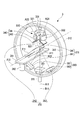
- FIG. 2 is a schematic configuration diagram showing a device configuration of the radiation therapy apparatus 3.
- the radiotherapy apparatus 3 includes a turning drive 311, an O-ring 312, a traveling gantry 313, a swing mechanism 321, an irradiation unit 330, a sensor array 351, a sensor array 361, and a sensor array 362.
- the irradiation unit 330 includes a therapeutic radiation irradiation device 331, a multi-leaf collimator (MLC) 332, a diagnostic X-ray source 341, and a diagnostic X-ray source 342.
- MLC multi-leaf collimator
- diagnostic X-ray source 341 and the diagnostic X-ray source 342 are collectively referred to as “diagnostic X-ray source 340”.
- sensor array 361 and the sensor array 362 are collectively referred to as “sensor array 360”.
- the turning drive device 311 supports the O-ring 312 on the base so as to be rotatable about the rotation axis A ⁇ b> 11, and rotates the O-ring 312 according to the control of the radiotherapy device control device 2.
- the rotation axis A11 is a vertical axis.
- the O-ring 312 is formed in a ring shape centered on the rotation axis A12, and supports the traveling gantry 313 so as to be rotatable about the rotation axis A12.
- the rotation axis A12 is a horizontal axis (that is, an axis perpendicular to the vertical direction), and is orthogonal to the rotation axis A11 at the isocenter P11.
- the rotation axis A12 is fixed with respect to the O-ring 312. That is, the rotation axis A12 rotates around the rotation axis A11 as the O-ring 312 rotates.
- the traveling gantry 313 is formed in a ring shape centered on the rotation axis A ⁇ b> 12, and is disposed inside the O-ring 312 so as to be concentric with the O-ring 312.
- the radiotherapy apparatus 3 further includes a travel drive device (not shown), and the travel gantry 313 rotates about the rotation axis A12 with power from the travel drive device.
- the traveling gantry 313 integrally rotates each part installed in the traveling gantry 313 such as the diagnostic X-ray source 341 and the sensor array 361, the diagnostic X-ray source 342 and the sensor array 362.
- the traveling gantry 313 corresponds to an example of a rotation mechanism in the present embodiment.
- the swing mechanism 321 is fixed inside the ring of the traveling gantry 313 and supports the irradiation unit 330 on the traveling gantry 313.
- the head swing mechanism 321 rotates the irradiation unit 330 about the pan axis A21 and rotates the irradiation unit 330 about the tilt axis A22 according to the control of the radiation therapy apparatus control device 2.
- the pan axis A21 is an axis parallel to the rotation axis A12 and is fixed to the traveling gantry 313.
- the head swing mechanism 321 rotates the irradiation unit 330 about the pan axis A21 so that the irradiation unit 330 moves to the left and right with respect to the rotation axis A12 (therefore, to the left and right with respect to the subject T11 shown in FIG. 2). Swing it.
- the tilt axis A22 is an axis orthogonal to the pan axis A21 and is fixed to the traveling gantry 313.
- the head swing mechanism 321 rotates the irradiation unit 330 about the tilt axis A22, thereby swinging the irradiation unit 330 in the direction of the rotation axis A12 (and thus up and down with respect to the subject T11).
- the irradiation unit 330 is disposed inside the traveling gantry 313 and supported by the swing mechanism 321 and irradiates therapeutic radiation B11 and diagnostic X-rays B21 and B22.
- the therapeutic radiation irradiation apparatus 331 irradiates the therapeutic radiation B11 according to the control of the radiotherapy apparatus control apparatus 2. Since the therapeutic radiation irradiation apparatus 331 is supported by the traveling gantry 313 via the swing mechanism 321, once the therapeutic radiation irradiation apparatus 331 is directed to the isocenter P ⁇ b> 11 by adjusting the swing mechanism 321, it is swiveled.
- the therapeutic radiation irradiation apparatus 331 can irradiate the therapeutic radiation B11 from various directions toward the isocenter P11 by rotating around the rotation axis A11 or the rotation axis A12.
- the traveling gantry 313 is bent due to the weight of the irradiation unit 330 or the like, or an affected part which is an irradiation target does not necessarily coincide with the isocenter P11.
- the swing mechanism 321 corrects the orientation of the therapeutic radiation irradiation apparatus 331. Thereby, highly accurate positioning can be performed.
- the multi-leaf collimator 332 shields a part of the therapeutic radiation B11 according to the control of the radiotherapy apparatus control apparatus 2, thereby matching the shape of the irradiation field when the therapeutic radiation B11 is irradiated to the patient to the shape of the affected part. .
- the diagnostic X-ray source 341 irradiates the diagnostic X-ray B21 toward the isocenter P11 under the control of the radiation therapy apparatus control apparatus 2.
- the diagnostic X-ray B21 is a cone-shaped cone beam such as a cone or a quadrangular pyramid that is emitted from one point of the diagnostic X-ray source 341 and has the one point as a vertex.
- the diagnostic X-ray source 342 emits diagnostic X-rays B22 toward the isocenter P11 under the control of the radiation therapy apparatus control apparatus 2.
- the diagnostic X-ray B22 is a cone-shaped cone beam such as a cone or a quadrangular pyramid that is emitted from one point of the diagnostic X-ray source 342 and has the one point as a vertex.
- FIG. 3 is an explanatory view showing an example of a cone beam irradiated by the diagnostic X-ray source 340.
- the cone beam emitted from the diagnostic X-ray source 340 is directed in a direction orthogonal to the rotation axis A12 (horizontal direction of the subject T11) and a direction of the rotation axis A12 (vertical direction of the subject T11). ) Is spreading to all of them.
- the fan angle which is an angle indicating the spread of the cone beam in the direction orthogonal to the rotation axis A12, is denoted by “ ⁇ ”.
- ⁇ represents a cone angle which is an angle indicating the spread of the cone beam in the direction of the rotation axis A12.
- the diagnostic X-rays B21 and B22 are both indicated by an irradiation axis.
- the cone beam irradiation axis here is the central axis of a cone formed by the cone beam (for example, when the cone beam is conical, the cone rotation axis).
- the diagnostic X-ray sources 341 and 342 are fixed to the irradiation unit 330 (for example, the housing of the multi-leaf collimator 332) with the irradiation axes orthogonal to each other.
- the diagnostic X-ray source 341 when the therapeutic radiation irradiation device 331 faces the isocenter P11 (that is, when the therapeutic radiation irradiation device 331 faces the direction in which the therapeutic radiation B11 passes through the isocenter P11), the diagnostic X-ray source 341
- the irradiation axis and the irradiation axis of the diagnostic X-ray source 342 are orthogonal to each other at the isocenter P11.
- the sensor array 351 is arranged at the position where the therapeutic radiation B11 from the therapeutic radiation irradiation apparatus 331 strikes and faces the therapeutic radiation irradiation apparatus 331, and is fixed inside the ring of the traveling gantry 313.
- the sensor array 351 receives the therapeutic radiation B11 emitted from the therapeutic radiation irradiation device 331 and transmitted through a subject such as an affected part, and generates (shoots) a fluoroscopic image (radiation projection image) of the subject.
- the fluoroscopic image of the subject generated by the sensor array 351 is used for confirming the irradiation position of the therapeutic radiation B11 and recording the treatment.
- light reception is receiving radiation.
- the sensor array 351 various devices that can receive the therapeutic radiation B11 and generate a fluoroscopic image can be used.
- the sensor array 351 may be an FPD (Flat Panel Detector) or an X-ray II (Image Intensifier).
- the sensor array 361 is arranged at the position where the diagnostic X-ray B21 from the diagnostic X-ray source 341 hits and faces the diagnostic X-ray source 341, and is fixed inside the ring of the traveling gantry 313. .
- the sensor array 361 receives the diagnostic X-ray B21 emitted from the diagnostic X-ray source 341 and transmitted through the subject such as an affected part, and generates a fluoroscopic image of the subject.
- the fluoroscopic image of the subject generated by the sensor array 361 is used together with the fluoroscopic image of the subject generated by the sensor array 362 for the radiotherapy device control apparatus 2 to generate a CT image.
- the sensor array 361 various devices capable of receiving a diagnostic X-ray B21 and generating a fluoroscopic image can be used.
- the sensor array 361 may be FPD or X-ray II.
- the sensor array 362 is arranged at the position where the diagnostic X-ray B22 from the diagnostic X-ray source 342 hits and faces the diagnostic X-ray source 342, and is fixed inside the ring of the traveling gantry 313. .
- the sensor array 362 receives the diagnostic X-ray B22 emitted from the diagnostic X-ray source 342 and transmitted through the subject such as the affected part, and generates a fluoroscopic image of the subject.
- the fluoroscopic image of the subject generated by the sensor array 362 and the fluoroscopic image of the subject generated by the sensor array 361 are used by the radiation therapy apparatus control device 2 to generate a CT image.
- various devices capable of receiving a diagnostic X-ray B22 and generating a fluoroscopic image can be used.
- the sensor array 362 may be FPD or X-ray II.
- the traveling gantry 313 is traveled along the O-ring 312, the diagnostic X-ray source 341 and the sensor array 361, the diagnostic X-ray source 342 and the sensor array 362, and the therapeutic radiation irradiation device 331 and the sensor array 351 are displayed. Respectively rotate around the rotation axis A12 passing through the isocenter P11 while maintaining the mutual positional relationship.
- the combination of the diagnostic X-ray source 341 and the sensor array 361 is referred to as “imager 371”, and the combination of the diagnostic X-ray source 342 and the sensor array 362 is referred to as “imager 372”.
- Both the imager 371 and the imager 372 correspond to an example of the imager in the present embodiment. That is, the diagnostic X-ray source 341 emits cone beam diagnostic X-rays B21 toward the rotation axis A12, and the sensor array 361 captures a fluoroscopic image based on the diagnostic X-rays B21.
- the diagnostic X-ray source 342 emits cone beam diagnostic X-rays B22 toward the rotation axis A12, and the sensor array 362 captures a fluoroscopic image based on the diagnostic X-rays B22.
- irradiating the cone beam toward the rotation axis means irradiating the cone beam so that the cone beam and the rotation axis intersect.
- the cone beam is irradiated so that the irradiation axis of the cone beam and the rotation axis intersect, but the embodiment of the present invention is not limited to this.
- the imager 371 is an example of a first imager and the imager 372 is an example of a second imager will be described as an example.
- the imager 372 may be an example of a first imager
- the imager 371 may be an example of a second imager.
- the angle between the irradiation axis of the imager 371 and the irradiation axis of the imager 372 is fixed at a predetermined angle with respect to the rotation axis A12.
- the irradiation axis of the imager here is the irradiation axis of the cone beam irradiated by the imager. More specifically, when the swing mechanism 321 sets the direction of the irradiation unit 330 so that the therapeutic radiation B11 passes through the isocenter P11, the irradiation axis of the diagnostic X-ray B21 and the irradiation axis of the diagnostic X-ray B22 Are orthogonal to each other at the isocenter P11 of the rotation axis A12.
- the traveling gantry 313 rotates, the imager 371 (diagnostic X-ray source 341 and sensor array 361) and the imager 372 (diagnostic X-ray source 342 and sensor array 362) rotate while maintaining the orthogonality of the irradiation axis. To do. At this point, the traveling gantry 313 rotates the imager 371 and the imager 372 together. As will be described later, the angle between the diagnostic X-ray B21 and the diagnostic X-ray B22 is not limited to 90 degrees (°).
- the couch 381 is used when the subject T11 who is a patient to be treated lies down.
- the couch 381 includes a fixture (not shown).
- the subject X-ray source 340 emits diagnostic X-rays and shoots a fluoroscopic image. Blur) and deviation of the irradiation position when the therapeutic radiation irradiation apparatus 331 irradiates the therapeutic radiation B11.
- the couch driving device 382 supports the couch 381 on the base and moves the couch 381 according to the control of the radiotherapy device control device 2.
- the couch driving device 382 moves the couch 381, the affected part of the subject T11 can be positioned at or near the isocenter P11.
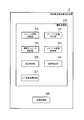
- FIG. 4 is a schematic block diagram illustrating a functional configuration of the radiation therapy apparatus control apparatus 2.
- the radiotherapy device control apparatus 2 includes an imaging processing unit 210 and a treatment control unit 220.
- the imaging processing unit 210 includes an imager rotation control unit 211, an imager position determination unit 212, an imaging timing control unit 213, an imager image acquisition unit 214, a position specification unit 215, an image correction unit 216, and a CT image reconstruction. Part 217.
- the imaging processing unit 210 controls the radiation therapy apparatus 3 (FIG. 2) to acquire a fluoroscopic image of the imaging target person T11, and generates a CT image based on the obtained fluoroscopic image.
- the CT image reconstruction unit 217 generates (reconstructs) a CT image from a fluoroscopic image captured by the sensor array 360 and corrected by the image correction unit 216 as described later.
- the affected part position for example, the center of gravity position corresponding to the shape (area) of the affected part image can be used.
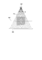
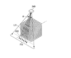
- FIGS. 5A to 5C are explanatory diagrams of CT image reconstruction performed by the CT image reconstruction unit 217.
- the cone beam emitted from the diagnostic X-ray source 340 has a fan angle ⁇ and a cone angle ⁇ .
- the cone beam emitted from the diagnostic X-ray source 340 is projected two-dimensionally (for example, on a rectangular region of the light receiving surface of the sensor array 360) onto the light receiving surface (the surface receiving the X-rays) of the sensor array 360. .
- the light receiving surface of the sensor array 360 is divided into pixels, and the CT image reconstruction unit 217 acquires density information for each pixel as fluoroscopic image data.
- This density information indicates the intensity of X-rays received by each pixel by the sensor array 360 (value after correction by the image correction unit 216).
- the pixels on the light receiving surface of the sensor array 360 are referred to as “pixels of the sensor array 360”.
- the CT image generation target space is divided into voxels corresponding to the pixels of the sensor array 360.
- the CT image reconstruction unit 217 converts the X-ray intensity for each pixel into the total value of the X-ray transmittance in each voxel through which the X-ray has passed.
- back projection the process of converting the X-ray intensity for each pixel into the total value of the X-ray transmittance in each voxel through which the X-ray has passed.
- FIG. 5A shows X-rays irradiated on the pixel rows of the sensor array 360 in a plane such as the plane F11.
- the row of pixels is an arrangement of pixels in a direction perpendicular to the rotation axis A12 (the left-right direction of the subject T11 shown in FIG. 2).
- each surface is shown by the line.
- FIG. 5B shows the X-rays irradiated to each pixel of the sensor array 360 with respect to the plane F11 by lines such as the line L11.
- FIG. 5C shows a voxel through which the line L11 passes.
- the line L11 passes through the voxels B11, B12, and B13, and the CT image reconstruction unit 217 calculates the X-ray intensity at the pixel corresponding to the line L11 as the total value of the X-ray transmittances of the voxels B11, B12, and B13. Backproject to.
- the CT image reconstruction unit 217 obtains fluoroscopic images obtained by projecting X-rays from various angles with respect to the subject (the affected part of the subject T11), and the pixels of the sensor array 360 for each fluoroscopic image. Back projection is performed every time. Then, the CT image reconstruction unit 217 calculates the X-ray transmittance for each voxel based on the obtained total value of the X-ray transmittances from various angles, and the obtained X-ray transmittance for each voxel. Based on the above, a CT image is generated.
- FIGS. 5A to 5C are examples for explanation, and are not limited to these.
- the positional relationship between the radiation source 340 or sensor array 360 and the voxels is not limited to that shown in FIGS. 5A to 5C.
- the imager rotation control unit 211 controls the traveling drive device of the radiotherapy apparatus 3 to rotate the traveling gantry 313, thereby diagnosing the X-ray source 341 and sensor array 361, diagnosing X-ray source 342 and sensor array 362. Rotate.
- the imager rotation control unit 211 rotates the imager 371 and the imager 372 and positions them at various angles with respect to the subject.
- FIG. 6 is an explanatory diagram illustrating an example of an angle at which the imager rotation control unit 211 rotates the imager.
- a line L21 shown in the figure indicates the rotation range of the imager 371, and a line L22 indicates the rotation range of the imager 372.
- a line L23 indicates a range obtained by combining the rotation range of the imager 371 and the rotation range of the imager 372.
- the diagnostic X-ray source 341 and the diagnostic X-ray source 342 are arranged so that the irradiation axes are orthogonal to each other.
- the rotation range of the imager 371 overlaps with the rotation range of the imager 372 by the imager rotation control unit 211 controlling the traveling drive device of the radiation therapy apparatus 3 to rotate the traveling gantry 313 by 90 degrees or more. Accordingly, when the rotation range of the imager 371 and the rotation range of the imager 372 are matched, the imager 371 can be rotated within an angle range of 180 degrees or more. As described above, by rotating the traveling gantry 313 by 90 degrees or more, the imager can be rotated in an angle range of 180 degrees or more with respect to the subject, so that the shooting time is halved compared with the case of one imager. Can be shortened.
- the imager rotation control unit 211 moves the traveling gantry 313 (hence, the imager 371 and the imager 372), 90 degrees + fan angle ⁇ (an angle obtained by adding the fan angle ⁇ to 90 degrees). Just rotate. Accordingly, the traveling gantry 313 rotates the imager 371 and the imager 372 more than 90 degrees (angle between the irradiation axis of the imager 371 and the irradiation axis of the imager 372 with respect to the rotation axis A12). This point will be described with reference to FIG.
- FIG. 7 is an explanatory diagram showing the X-ray angle passing through the end of the fan angle of the cone beam when the rotation range of the imager is 180 degrees.
- the point P21 shown in the figure is located on a line L31 at the end of the fan angle ⁇ of the cone beam irradiated by the diagnostic X-ray source 340 when the diagnostic X-ray source 340 starts to rotate.
- the diagnostic X-ray source 340 is at a position rotated 180 degrees from the position at the start of rotation, the point P21 is on the line L32 at the end of the fan angle ⁇ of the cone beam irradiated by the diagnostic X-ray source 340. Is located.
- the direction of the X-ray passing through the point P21 changes within an angle range obtained by subtracting the fan angle ⁇ from 180 degrees as shown in FIG.
- the CT image reconstruction unit 217 in order for the CT image reconstruction unit 217 to generate a high-accuracy CT image, information on each voxel irradiated with X-rays from each direction within a range of 180 degrees or more (for each pixel of the sensor array 360). It is preferable to obtain (concentration information). Therefore, the imager rotation control unit 211 controls the traveling drive device to rotate the traveling gantry 313 by 90 degrees + fan angle ⁇ .
- the rotation range obtained by combining the rotation range of the imager 371 and the rotation range of the imager 372 is 180 degrees + fan angle ⁇
- the CT image reconstruction unit 217 can perform any direction within a range of 180 degrees or more for any voxel.
- Information can be obtained by irradiating with X-rays.
- the imager position determination unit 212 acquires position information of the imager 371 (information indicating the amount of rotation of the imager 371), and an overlapping area where the rotation range of the imager 371 and the rotation range of the imager 372 overlap (hereinafter simply referred to as “overlapping area”).
- the imager 371 is positioned.
- various methods can be used as a method by which the imager position determination unit 212 acquires the position information of the imager 371.
- the imager position determination unit 212 acquires control information for the travel drive device from the imager rotation control unit 211, and based on the control information, the reference position of the diagnostic X-ray source 340 (for example, the position at the start of rotation) ) May be calculated as position information of the imager 371.
- the traveling gantry 313 measures its own rotation angle, and the imager position determination unit 212
- the rotation angle may be acquired as position information of the imager 371 (rotation angle of the imager 371).
- the imager position determination unit 212 determines whether or not the imager 371 is located in the overlapping region by determining whether or not the rotation amount of the imager 371 is 90 degrees or more based on the position information of the imager 371. . That is, when the rotation amount of the imager 371 is 90 degrees or more, the imager 371 is located in the overlapping region.
- the shooting timing control unit 213 When detecting the arrival of the shooting timing, the shooting timing control unit 213 causes one or both of the imager 371 and the imager 372 to perform shooting. Specifically, the imaging timing control unit 213 outputs control information for instructing imaging to one or both of the imager 371 and the imager 372 for each time preset as an imaging cycle. To do. At that time, the imaging timing control unit 213 causes only the imager 372 to perform imaging at at least one of the imaging timings when arrival is detected in a state where the imager position determination unit 212 determines that the imager 371 is positioned in the overlapping region. .
- the imaging timing control unit 213 causes only the imager 372 to perform imaging at all of the imaging timings when arrival is detected in a state where the imager position determination unit 212 determines that the imager 371 is positioned in the overlapping region. That is, when the imager position determination unit 212 determines that the rotation amount of the imager 371 is 90 degrees or more, the shooting timing control unit 213 outputs control information for instructing shooting only to the imager 372.
- the shooting timing control unit 213 when only one of the imager 371 and the imager 372 performs shooting at one shooting timing is referred to as “one-side shooting”. Also, the fact that both the imager 371 and the imager 372 perform shooting at one shooting timing is referred to as “simultaneous shooting”.
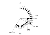
- FIG. 8 is an explanatory diagram of a first example of shooting timing control.
- the imaging timing of 13 times is set while the imager 371 and the imager 372 are rotated by 90 degrees + the fan angle ⁇ .
- a line L41 indicates the rotation range of the diagnostic X-ray source 341
- a line L42 indicates the rotation range of the diagnostic X-ray source 342.
- the shooting timing control unit 213 instructs the imager 371 and the imager 372 to perform simultaneous shooting.
- the imager 371 is located in the overlapping area at the tenth and subsequent shooting timings. Therefore, even if the imager 371 stops photographing, the CT image reconstruction unit 217 can obtain a perspective image of 180 degrees + fan angle ⁇ , and any voxel can be obtained from each direction within a range of 180 degrees or more. Information obtained by X-ray irradiation can be obtained.
- the shooting timing control unit 213 instructs only the imager 372 to perform shooting (one-side shooting).
- the shooting timing control unit 213 instructs only the imager 372 to perform shooting (shooting the imager 371).
- the amount of radiation irradiation can be reduced.
- the radiation dose for four times is reduced for the imager 371 as compared with the case where the imager 371 emits radiation at the imaging timings from the 10th time to the 13th time.
- the photographing timing shown in FIG. 8 is an example for explanation, and the present invention is not limited to this.
- the number of shooting timings at which the shooting timing control unit 213 detects arrival is not limited to 13.
- FIG. 9 is an explanatory diagram of a second example of photographing timing control.
- the imaging timing of 13 times is set while the imager 371 and the imager 372 are rotated by 90 degrees + the fan angle ⁇ .
- a line L41 indicates the rotation range of the diagnostic X-ray source 341
- a line L42 indicates the rotation range of the diagnostic X-ray source 342.
- the shooting timing shown in FIG. 9 is an example for explanation, and the present invention is not limited to this.
- the shooting timing control unit 213 instructs the imager 371 and the imager 372 to perform simultaneous shooting. .
- the shooting timing control unit 213 applies only to the imager 372 at the 11th and 13th shooting timings, as in FIG. An instruction is given to perform shooting (one-sided shooting).
- the shooting timing control unit 213 instructs the imager 371 and the imager 372 to perform simultaneous shooting.
- the position specifying unit 215 determines the position of the position specifying target (the affected part that is the irradiation target of the therapeutic radiation B11 in this embodiment) three-dimensionally. Can be identified.
- the image correction unit 216 can correct the fluoroscopic image even when the position specifying target moves in the direction of the diagnostic X-ray B21 or the direction of the diagnostic X-ray B22.
- various criteria can be used as the determination criterion for the imaging timing control unit 213 to switch between simultaneous imaging and one-side imaging.
- the image correction unit 216 does not specify the three-dimensional position for each imaging timing, but the image correction unit 216 performs the breathing of the subject T11.
- the fluoroscopic image can be corrected for subject blurring in the diagnostic X-ray direction caused by the above.
- the image correcting unit 216 may use the three-dimensional position at the imaging timing from when the position specifying unit 215 specifies the three-dimensional position of the position specifying target to a predetermined time.
- the position specifying unit 215 sets the position specifying target for each shooting timing within a time period in which the motion of the position specifying target can be regarded as a constant velocity linear motion.
- a three-dimensional position may be calculated.
- the imaging timing control unit 213 performs the imaging timing control unit 213 during the imaging timing a predetermined number of times (one or more times) after the position specifying unit 215 successfully specifies the three-dimensional position of the position specifying target. Only the imager 372 may be photographed (one-sided photographing).
- the shooting timing control unit 213 detects the arrival of the shooting timing, causes both the imager 371 and the imager 372 to perform shooting (simultaneous shooting), and based on the obtained fluoroscopic image, the position specifying unit 215
- the imaging timing control unit 213 detects the arrival of the next imaging timing in a state where the imager position determination unit 212 determines that the imager 371 is positioned in the overlapping region. Then, only the imager 372 may perform shooting (one-side shooting).
- the position specifying target when the imaging cycle is short, if the position specifying target is hidden behind a bone or the like in the fluoroscopic image of the imager 371 or the imager 372, the position specifying target may remain hidden for a while. In the meantime, even if the imager 371 and the imager 372 perform simultaneous shooting, the position specifying unit 215 may continue to fail to specify the three-dimensional position.
- the imaging timing control unit 213 performs the imaging timing control unit 213 for a predetermined number of times (one or more times) after the position specifying unit 215 fails to specify the three-dimensional position of the position specifying target. Only the imager 372 may be photographed (one-sided photographing). As described above, the photographing timing control unit 213 detects the arrival of the photographing timing and causes both the imager 371 and the imager 372 to perform photographing (simultaneous photographing), and the position specifying unit 215 in at least one of the obtained fluoroscopic images.
- the imaging timing control unit 213 detects the arrival of the next imaging timing in a state in which the imager position determination unit 212 determines that the imager 371 is positioned in the overlapping region when the detection of the position target image fails. Only the imager 372 may perform shooting (one-side shooting).
- the imaging timing control unit 213 stores an imaging plan determined by a doctor or the like in advance, and when the imager 371 is located in the overlapping area, switching between simultaneous imaging and one-side imaging is performed according to the imaging plan. May be.
- the imager image acquisition unit 214 acquires a fluoroscopic image (fluoroscopic image data) taken by the imager 371 and a fluoroscopic image (fluoroscopic image data) taken by the imager 372 from the radiotherapy apparatus 3 and outputs them to the position specifying unit 215.
- the position specifying unit 215 specifies a three-dimensional position of a position specifying target (hereinafter described as an affected part) based on the fluoroscopic image taken by the imager 371 and the fluoroscopic image taken by the imager 372. That is, the position of the affected part in the depth direction cannot be specified from only one fluoroscopic image, whereas the position specifying unit 215 uses another fluoroscopic image simultaneously photographed from another direction, so that the depth direction can also be determined.
- the affected part position can be specified.
- the position specifying unit 215 first specifies the affected part position by image matching (template matching) for each of the fluoroscopic images obtained by the imager 371 and the imager 372 taking images simultaneously.
- Information on the shape of the affected part (template) for image matching is generated by a doctor based on a fluoroscopic image (an X-ray image) taken in advance and given to the position specifying unit 215, for example.
- the position specifying unit 215 determines the three-dimensional position of the affected area based on the position information of the affected area in both images. Identify.
- an existing method such as the method shown in Japanese Patent No. 404952 can be used.
- the image correction unit 216 corrects the position of the affected part with respect to the fluoroscopic image captured by the imager 371 and the fluoroscopic image captured by the imager 372.
- the position of the affected part may be shifted due to respiration of the photographing subject T11 due to a difference in photographing timing. Due to the displacement of the affected area, the accuracy of the CT image may be reduced. Therefore, the image correction unit 216 corrects the position of the affected area (corrects the image closer to the fluoroscopic image when the affected area is not moving), thereby reducing the accuracy of the CT image.
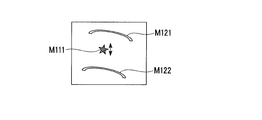
- FIG. 10 is a diagram illustrating an example of a fluoroscopic image in a case where the position of the affected part is shifted.
- the fluoroscopic image shown in the figure includes an image M111 of the affected area and bone images M121 and M122.
- the position of the affected part is moving according to the respiration of the subject T11.
- the bone positions shown in the images M121 and M122 are not moved.
- the image correction unit 216 reduces the influence of the displacement of the affected part position on the CT image by moving the position of the affected part image while keeping the positions of the bone images M121 and M122 in the fluoroscopic image.
- a method for moving the position of the affected part image by the image correcting unit 216 an existing method such as a method using an optical flow disclosed in JP-A-2001-259059 can be used.
- the image correcting unit 216 translates the position of the affected part image to the vector opposite to the displacement vector of the affected part indicated by the optical flow.
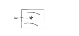
- FIGS. 11A to 11B are explanatory diagrams illustrating an example of correction of a fluoroscopic image with respect to the movement of the affected part position in the diagnostic X-ray direction, which is performed by the image correction unit 216.
- FIG. FIG. 11A shows an example of a fluoroscopic image before correction
- FIG. 11B shows an example of a fluoroscopic image after correction.
- the affected part is shifted to the diagnostic X-ray source 340 side.
- the image correction unit 216 performs correction to reduce the image of the affected part, as in the case of the affected part image M212 in FIG. 11B, when the affected part is closer to the sensor array 360.
- an existing method such as a method of performing optical flow calculation three-dimensionally can be used.
- the image correction unit 216 can calculate the optical flow three-dimensionally, thereby removing the influence of the shift of the shooting angle at each shooting timing. For example, in the fluoroscopic image captured by the imager 371 at the first capturing timing in FIG. 9 and the fluoroscopic image captured by the imager 371 at the second capturing timing, a shift occurs in the capturing direction. This shift in the photographing direction can be an error in calculating the two-dimensional optical flow.
- the position specifying unit 215 specifies the position of the affected part with the three-dimensional coordinates fixed to the subject T11, the three-dimensional coordinates are constant regardless of the shooting direction, and thus when calculating the optical flow. In addition, it is possible to eliminate the influence of a shift in the shooting direction.
- the image correction unit 216 may correct the rotation axis A12 direction (body axis direction) based on the fluoroscopic image obtained by the simultaneous photographing. For example, when determining the affected part position by image matching that determines the affected part position due to the unclear outline of the image of the affected part, deformation of the affected part, or shadows of other organs reflected in the affected part. An error may occur in the direction of the rotation axis A12. In such a case, for example, by taking the average of the position of the affected part in the direction of the rotation axis A12 between the fluoroscopic image captured by the imager 371 and the fluoroscopic image captured by the imager 372 in simultaneous imaging, the size of the error can be reduced. it can.
- the image correcting unit 216 acquires an image of the corresponding organ from another fluoroscopic image. Thus, it may be added to the fluoroscopic image to be corrected.
- the treatment control unit 220 controls the radiation treatment apparatus 3 when the treatment radiation B11 is irradiated.
- the treatment control unit 220 controls the position of the therapeutic radiation irradiation device 331 and the irradiation time of the therapeutic radiation B11 according to a treatment plan formulated by a doctor based on the CT image generated by the CT image reconstruction unit 217.
- Various controls such as control and control of the multi-leaf collimator 332 are performed.
- a computer can be used as the radiotherapy apparatus control apparatus 2.
- each unit of the radiotherapy apparatus control apparatus 2 is realized by a CPU (Central Processing Unit) included in the computer reading and executing a program from a storage device included in the computer.
- an apparatus other than a computer may be used as the radiation therapy apparatus control device 2 such that each unit of the radiation therapy apparatus control apparatus 2 is configured by dedicated hardware.
- FIG. 12 is a flowchart illustrating a procedure of processing performed by the imaging processing unit 210.
- the imaging processing unit 210 starts the process illustrated in FIG.
- the imaging processing unit 210 first performs calibration (step S101).
- the imager rotation control unit 211 adjusts the positions of the imager 371 and the imager 372 to the initial position, and adjusts the direction of the irradiation axis of the imager 371 and the imager 372 to the direction passing through the isocenter P11.
- the imaging timing control unit 213 performs response performance calibration that matches the response performance of the sensor array 361 and the sensor array 362.
- the imager rotation control unit 211 controls the travel drive device to rotate the travel gantry 313 at a constant speed (step S102). Then, the shooting timing control unit 213 determines whether or not the shooting timing has come (step S103). Specifically, the shooting timing control unit 213 has a timer function and detects the arrival of the shooting timing at every predetermined time set in advance as a shooting cycle.
- step S103 when the shooting timing control unit 213 determines that the shooting timing has come (step S103: YES), the shooting timing control unit 213 selects one-side shooting or simultaneous shooting (step S111). Specifically, as described above, when the imager position determination unit 212 determines that the imager 371 is not located in the overlapping region, the shooting timing control unit 213 instructs the imager 371 and the imager 372 to perform simultaneous shooting. . On the other hand, when the imager position determination unit 212 determines that the imager 371 is located in the overlapping region, the imaging timing control unit 213 determines whether to perform one-side shooting or the one-shot shooting based on a previously acquired shooting plan or a preset logic. Select simultaneous shooting and instruct shooting according to the selection.
- the imager image acquisition unit 214 acquires the fluoroscopic image (perspective image data) (step S112).
- the position specifying unit 215 calculates the three-dimensional position of the affected part as described above (step S113).
- the image correction unit 216 performs the above-described correction of the affected part position on the image captured by the imager 371 and the image captured by the imager 372. In particular, when the three-dimensional position information of the affected part is obtained from the position specifying unit 215, the image correcting unit 216 corrects the affected part position with respect to the movement of the affected part in the direction of the diagnostic X-ray (step S114). ).
- the CT image reconstruction unit 217 performs CT image reconstruction calculation (step S115). Specifically, the CT image reconstruction unit 217 performs the back projection described above based on the projection image corrected by the image correction unit 216. Then, the imaging processing unit 210 determines whether or not imaging from all angles has been completed (step S116). For example, the imager position determination unit 212 acquires the rotation amount of the traveling gantry 313 and determines whether the rotation amount is 90 degrees + ⁇ or more.
- step S116 If it is determined that shooting from all angles has not been completed (step S116: NO), the process returns to step S102.
- step S116: YES the CT image reconstruction unit 217 calculates a radiation transmission amount for each voxel from the backprojection result to reconstruct a tomographic image.
- the obtained tomographic image is output (step S121).
- the CT image reconstruction unit 217 stores the tomographic image in the storage device included in the radiation therapy apparatus control apparatus 2 and displays the tomographic image on the display screen of the radiation therapy apparatus control apparatus 2.
- the imager rotation control unit 211 ends the output of the rotation instruction in step S102, and the traveling gantry 313 stops (stops the rotation). Thereafter, the process of FIG.
- step S103 determines in step S103 that the shooting timing has not arrived
- the imaging timing control unit 213 performs imaging only on the imager 372 at least at one of the imaging timings when arrival is detected in a state where the imager position determination unit 212 determines that the imager 371 is located in the overlapping region. Let it be done. Since the imaging timing control unit 213 causes only the imager 372 to perform imaging, it is possible to reduce the irradiation amount of the radiation from the imager 371 at the imaging timing. In particular, in a state where the imager 371 is not located in the overlapping area, the imaging timing control unit 213 causes the imager 371 and the imager 372 to perform simultaneous imaging so that a fluoroscopic image of 180 degrees + fan angle ⁇ is captured. Can do. In this regard, the imaging timing control unit 213 can reduce the radiation dose without reducing the accuracy of the CT image.
- the shooting timing control unit 213 detects the arrival of the shooting timing, causes the imager 371 and the imager 372 to perform simultaneous shooting, and the position specifying unit 215 determines the three-dimensional position of the position specifying target based on the obtained fluoroscopic image. If the imager position determination unit 212 determines that the imager 371 is located in the overlapping area, and the arrival of the next shooting timing is detected, only the imager 372 performs shooting (one side). In this case, at the shooting timing when the imager 372 performs one-side shooting, the image correction unit 216 calculates the three-dimensional position of the position specifying target specified by the position specifying unit 215 based on the simultaneous shooting or the three-dimensional position. Based on the new three-dimensional position, it is possible to correct the movement of the position specifying target in the diagnostic X-ray direction. In this respect, the radiation dose can be reduced while increasing the accuracy of the CT image.
- the imaging timing control unit 213 detects the arrival of the imaging timing, causes the imager 371 and the imager 372 to perform simultaneous imaging, and at least one of the obtained fluoroscopic images, the position specifying unit 215 determines the image of the position specifying target image.
- the detection fails, when the imager position determination unit 212 determines that the imager 371 is positioned in the overlapping area and detects the arrival of the next shooting timing, only the imager 372 performs shooting (one side).
- the photographing timing control unit 213 performs simultaneous photographing at a photographing timing that is highly likely to cause the position specifying unit 215 to fail to specify the three-dimensional position of the position specifying target even if the imager 371 and the imager 372 perform simultaneous shooting. Can be stopped to reduce the radiation dose.
- the imaging timing control unit 213 performs imaging (one-sided imaging) only on the imager 372 at all the imaging timings at which arrival is detected in a state where the imager position determination unit 212 determines that the imager 371 is positioned in the overlapping region. Make it. Thereby, the radiation dose can be further reduced.
- the target of control in the present embodiment is not limited to the radiation therapy apparatus.
- an apparatus dedicated to CT can also be a control target in the present embodiment.
- the configuration of the CT-dedicated device for example, each unit (the therapeutic radiation irradiation device 331, the multi-leaf collimator 332, and the sensor array 351) for irradiation with the therapeutic radiation B11 is excluded from the configuration illustrated in FIG. It can be configured.
- the structure by the side of a control apparatus it can be set as the structure remove
- the imager 371 may correspond to an example of a second imager, and the imager 372 may correspond to an example of a first imager. In this case, at least part of the timing at which the imager 372 is located in the overlapping area, only the imager 371 can perform one-side shooting, and the imager 371 can perform shooting from the overlapping area. Furthermore, both the imager 371 and the imager 372 may correspond to any one example of the first imager and the second imager, such that the imager 371 and the imager 372 alternately perform shooting in the overlapping region. .
- the angle between the irradiation angle of the imager 371 and the irradiation angle of the imager 372 with respect to the rotation axis A12 is limited to 90 degrees as described above. Any angle may be used.
- the number of imagers included in the radiotherapy apparatus or CT dedicated apparatus to be controlled is not limited to two as described above, and may be three or more.
- the radiotherapy apparatus 3 may include a third imager in addition to the imagers 371 and 372.
- the angle between the irradiation axis of the imager 371 and the irradiation axis of the imager 372 with respect to the rotation axis A12 is 60 degrees, and the irradiation axis of the imager 372 and the irradiation axis of the third imager with respect to the rotation axis A12.
- the angle may be 60 degrees.
- the shooting timing control unit 213 can select one of shooting by one imager, shooting by two imagers, and shooting by three imagers at each shooting timing.
- the irradiation axis of the imager 371 and the irradiation axis of the imager 372 pass through the vicinity of the isocenter P11, and it is not always necessary to pass through the isocenter P11. Further, the irradiation axis of the imager 371 and the irradiation axis of the imager 372 do not necessarily cross each other (they may be in a twisted position relationship).
- a computer can be used as the radiotherapy apparatus control apparatus 2. Therefore, a program for realizing all or a part of the functions of each unit of the radiotherapy apparatus control apparatus 2 is recorded on a computer-readable recording medium, and the program recorded on the recording medium is read by a computer system. The processing of each unit may be performed by executing.
- the “computer system” includes an OS and hardware such as peripheral devices. Further, the “computer system” includes a homepage providing environment (or display environment) if a WWW system is used.
- the “computer-readable recording medium” refers to a storage device such as a flexible medium, a magneto-optical disk, a portable medium such as a ROM or a CD-ROM, and a hard disk incorporated in a computer system.
- the “computer-readable recording medium” dynamically holds a program for a short time like a communication line when transmitting a program via a network such as the Internet or a communication line such as a telephone line.
- a volatile memory in a computer system serving as a server or a client in that case and a program that holds a program for a certain period of time are also included.
- the program may be a program for realizing a part of the functions described above, and may be a program capable of realizing the functions described above in combination with a program already recorded in a computer system.
- the first imager and the second imager that shoot a fluoroscopic image by irradiating a cone beam toward the rotation axis, and the first imager and the second imager around the rotation axis are integrated.
- a rotation control mechanism for rotating the image pickup apparatus of the image pickup apparatus wherein an angle between an irradiation axis of the first imager and an irradiation axis of the second imager is a predetermined angle with respect to the rotation axis.
- An imager position determination unit that determines whether or not an image capture timing has arrived, and one of the first imager and the second imager is detected.
- a photographing timing control unit that causes both to perform photographing, and at least one of photographing timings in which arrival is detected in a state in which the imager position determination unit determines that the first imager is located in the overlapping region.
- the present invention relates to a photographing control apparatus comprising: a photographing timing control unit that causes only the second imager to perform photographing. According to the present invention, the radiation dose can be reduced.
Landscapes
- Health & Medical Sciences (AREA)
- Life Sciences & Earth Sciences (AREA)
- Engineering & Computer Science (AREA)
- Medical Informatics (AREA)
- Biomedical Technology (AREA)
- Pathology (AREA)
- Nuclear Medicine, Radiotherapy & Molecular Imaging (AREA)
- Radiology & Medical Imaging (AREA)
- Animal Behavior & Ethology (AREA)
- General Health & Medical Sciences (AREA)
- Public Health (AREA)
- Veterinary Medicine (AREA)
- Biophysics (AREA)
- High Energy & Nuclear Physics (AREA)
- Physics & Mathematics (AREA)
- Optics & Photonics (AREA)
- Heart & Thoracic Surgery (AREA)
- Molecular Biology (AREA)
- Surgery (AREA)
- Pulmonology (AREA)
- Theoretical Computer Science (AREA)
- Apparatus For Radiation Diagnosis (AREA)
- Cameras In General (AREA)
- Studio Devices (AREA)
Description
本発明は、撮影制御装置、撮影システム、撮影制御方法およびプログラムに関する。
本願は、2012年10月9日に、日本国に出願された特願2012-224248号に基づき優先権を主張し、その内容をここに援用する。
本願は、2012年10月9日に、日本国に出願された特願2012-224248号に基づき優先権を主張し、その内容をここに援用する。
コーンビームCT(cone beam computed tomography;CBCT)では、X線源と2次元検出器とが対になったイメージャが、撮影対象の回りを回転して照射角度を変えながら、円錐状など錐体状(コーン状)のX線を、X線源から2次元検出器に照射して2次元透視画像の撮影を行う。錐体状のX線を用いることで、コーンビームCTでは、撮影中に撮影対象を動かす必要無しに、また、複数回の回転を必要とせずに、2次元透視画像の撮影を行ってCT画像(断層画像)を生成(再構成)することができる。
ここで、人体を対象としてCTスキャンを行う場合、撮影対象者の呼吸に起因する被写体ぶれが生じると、CT画像の精度を低下させる要因となる。かかる被写体ぶれを防止するために、撮影の間、撮影対象者が息止めを行う方法が用いられているが、息止めの時間が長いと撮影対象者にとって負担となってしまう。従って、撮影対象者の負担を低減させつつ高精度な画像を取得するためには、撮影時間は短い方が好ましい。
撮影時間を短縮可能な装置として、二対のイメージャを用いるデュアルソースCBCTなど、複数のイメージャを用いることでイメージャの回転角度を比較的小さく抑えるCBCTがある(例えば、特許文献1)。
撮影時間を短縮可能な装置として、二対のイメージャを用いるデュアルソースCBCTなど、複数のイメージャを用いることでイメージャの回転角度を比較的小さく抑えるCBCTがある(例えば、特許文献1)。
デュアルソースCBCTなど、複数のイメージャを用いるCBCTにおいて、放射線照射量を低減させることができれば、撮影対象者の負担を軽減させることができる。
本発明は、放射線照射量を低減させることのできる撮影制御装置、撮影システム、撮影制御方法およびプログラムを提供する。
本発明の一態様による撮影制御装置は、回転軸に向けてコーンビームを照射して透視画像の撮影を行う第1イメージャおよび第2イメージャと、前記回転軸を中心に前記第1イメージャと前記第2イメージャとを一体的に回転させる回転機構とを具備し、前記回転軸を基準として前記第1イメージャの照射軸と前記第2イメージャの照射軸との角度が所定角度である撮影装置の撮影制御装置において、前記回転機構が前記第1イメージャと前記第2イメージャとを前記所定角度よりも大きく回転させる場合に、前記第1イメージャの回転範囲と前記第2イメージャの回転範囲とが重なる重複領域に前記第1イメージャが位置するか否かを判定するイメージャ位置判定部と、撮影タイミングの到来を検出すると前記第1イメージャと前記第2イメージャとのいずれか一方または両方に撮影を行わせる撮影タイミング制御部であって、前記重複領域に前記第1イメージャが位置すると前記イメージャ位置判定部が判定している状態で到来を検出した撮影タイミングの少なくとも1つにおいて、前記第2イメージャのみに撮影を行わせる撮影タイミング制御部と、を具備する。
また、本発明の他の態様による撮影制御装置は、上述の撮影制御装置であって、前記第1イメージャが撮影した透視画像と前記第2イメージャが撮影した透視画像とに基づいて位置特定対象の三次元位置を特定する位置特定部を具備し、前記撮影タイミング制御部は、撮影タイミングの到来を検出して前記第1イメージャと前記第2イメージャとの両方に撮影を行わせ、得られた透視画像に基づいて前記位置特定部が前記位置特定対象の三次元位置の特定に成功した場合、前記重複領域に前記第1イメージャが位置すると前記イメージャ位置判定部が判定している状態で、次の撮影タイミングの到来を検出すると、前記第2イメージャのみに撮影を行わせる。
また、本発明の他の態様による撮影制御装置は、上述の撮影制御装置であって、前記第1イメージャが撮影した透視画像と前記第2イメージャが撮影した透視画像とに基づいて位置特定対象の三次元位置を特定する位置特定部を具備し、前記撮影タイミング制御部は、撮影タイミングの到来を検出して前記第1イメージャと前記第2イメージャとの両方に撮影を行わせ、得られた透視画像の少なくとも一方において前記位置特定部が前記位置特定対象の画像の検出に失敗した場合、前記重複領域に前記第1イメージャが位置すると前記イメージャ位置判定部が判定している状態で、次の撮影タイミングの到来を検出すると、前記第2イメージャのみに撮影を行わせる。
また、本発明の他の態様による撮影制御装置は、上述の撮影制御装置であって、前記撮影タイミング制御部は、前記重複領域に前記第1イメージャが位置すると前記イメージャ位置判定部が判定している状態で到来を検出した撮影タイミングの全部において、前記第2イメージャのみに撮影を行わせる。
また、本発明の他の態様による撮影システムは、回転軸に向けてコーンビームを照射して透視画像の撮影を行う第1イメージャおよび第2イメージャと、前記回転軸を中心に前記第1イメージャと前記第2イメージャとを一体的に回転させる回転機構とを具備し、前記回転軸を基準として前記第1イメージャの照射軸と前記第2イメージャの照射軸との角度が所定角度である撮影装置と、前記回転機構が前記第1イメージャと前記第2イメージャとを前記所定角度よりも大きく回転させる場合に、前記第1イメージャの回転範囲と前記第2イメージャの回転範囲とが重なる重複領域に前記第1イメージャが位置するか否かを判定するイメージャ位置判定部と、撮影タイミングの到来を検出すると前記第1イメージャと前記第2イメージャとのいずれか一方または両方に撮影を行わせる撮影タイミング制御部であって、前記重複領域に前記第1イメージャが位置すると前記イメージャ位置判定部が判定している状態で到来を検出した撮影タイミングの少なくとも1つにおいて、前記第2イメージャのみに撮影を行わせる撮影タイミング制御部と、を具備する撮影制御装置と、を備える。
また、本発明の他の態様による撮影制御方法は、回転軸に向けてコーンビームを照射して透視画像の撮影を行う第1イメージャおよび第2イメージャと、前記回転軸を中心に前記第1イメージャと前記第2イメージャとを一体的に回転させる回転機構とを具備し、前記回転軸を基準として前記第1イメージャの照射軸と前記第2イメージャの照射軸との角度が所定角度である撮影装置の撮影制御装置の撮影制御方法であって、前記回転機構が前記第1イメージャと前記第2イメージャとを前記所定角度よりも大きく回転させる場合に、前記第1イメージャの回転範囲と前記第2イメージャの回転範囲とが重なる重複領域に前記第1イメージャが位置するか否かを判定するイメージャ位置判定ステップと、撮影タイミングの到来を検出すると前記第1イメージャと前記第2イメージャとのいずれか一方または両方に撮影を行わせる撮影タイミング制御ステップであって、前記重複領域に前記第1イメージャが位置すると前記イメージャ位置判定ステップにて判定している状態で到来を検出した撮影タイミングの少なくとも1つにおいて、前記第2イメージャのみに撮影を行わせる撮影タイミング制御ステップと、を具備する。
また、本発明の他の態様によるプログラムは、回転軸に向けてコーンビームを照射して透視画像の撮影を行う第1イメージャおよび第2イメージャと、前記回転軸を中心に前記第1イメージャと前記第2イメージャとを一体的に回転させる回転機構とを具備し、前記回転軸を基準として前記第1イメージャの照射軸と前記第2イメージャの照射軸との角度が所定角度である撮影装置の撮影制御装置としてのコンピュータに、前記回転機構が前記第1イメージャと前記第2イメージャとを前記所定角度よりも大きく回転させる場合に、前記第1イメージャの回転範囲と前記第2イメージャの回転範囲とが重なる重複領域に前記第1イメージャが位置するか否かを判定するイメージャ位置判定ステップと、撮影タイミングの到来を検出すると前記第1イメージャと前記第2イメージャとのいずれか一方または両方に撮影を行わせる撮影タイミング制御ステップであって、前記重複領域に前記第1イメージャが位置すると前記イメージャ位置判定ステップにて判定している状態で到来を検出した撮影タイミングの少なくとも1つにおいて、前記第2イメージャのみに撮影を行わせる撮影タイミング制御ステップと、を実行させるためのプログラムである。
上記した撮影制御装置、撮影システム、撮影制御方法およびプログラムによれば、放射線照射量を低減させることができる。
以下、発明の実施の形態を通じて本発明を説明するが、以下の実施形態は請求の範囲にかかる発明を限定するものではない。また、実施形態の中で説明されている特徴の組み合わせの全てが発明の解決手段に必須であるとは限らない。
図1は、本発明の一実施形態における撮影システムの機能構成を示す概略ブロック図である。同図において、放射線治療システム1は、放射線治療装置制御装置2と、放射線治療装置3とを具備する。
図1は、本発明の一実施形態における撮影システムの機能構成を示す概略ブロック図である。同図において、放射線治療システム1は、放射線治療装置制御装置2と、放射線治療装置3とを具備する。
放射線治療システム1は、放射線治療における放射線(重粒子線でもよい)の照射(患部など、ある対象へ向けての放射)や、治療計画策定のためのCT画像(断層画像)の生成を行う。放射線治療システム1は、本実施形態における撮影システムの一例に該当する。
放射線治療装置3は、放射線治療において、患部への放射線の照射を行う。また、放射線治療装置3は、CT画像生成のために、透視画像(X線透視画像)を撮影する。放射線治療装置3は、本実施形態における撮影装置の一例に該当する。
放射線治療装置制御装置2は、放射線治療装置3を制御して、放射線の照射や透視画像の撮影を行わせる。また、放射線治療装置制御装置2は、放射線治療装置3が撮影した透視画像に基づいてCT画像を生成する。放射線治療装置制御装置2は、本実施形態における撮影制御装置の一例に該当する。
放射線治療装置3は、放射線治療において、患部への放射線の照射を行う。また、放射線治療装置3は、CT画像生成のために、透視画像(X線透視画像)を撮影する。放射線治療装置3は、本実施形態における撮影装置の一例に該当する。
放射線治療装置制御装置2は、放射線治療装置3を制御して、放射線の照射や透視画像の撮影を行わせる。また、放射線治療装置制御装置2は、放射線治療装置3が撮影した透視画像に基づいてCT画像を生成する。放射線治療装置制御装置2は、本実施形態における撮影制御装置の一例に該当する。
図2は、放射線治療装置3の装置構成を示す概略構成図である。同図において、放射線治療装置3は、旋回駆動装置311と、Oリング312と、走行ガントリ313と、首振り機構321と、照射部330と、センサアレイ351と、センサアレイ361と、センサアレイ362と、カウチ381と、カウチ駆動装置382とを具備する。照射部330は、治療用放射線照射装置331と、マルチリーフコリメータ(Multi Leaf Collimator;MLC)332と、診断用X線源341と、診断用X線源342とを具備する。
なお、以下では、診断用X線源341と診断用X線源342とを総称して「診断用X線源340」と表記する。また、以下では、センサアレイ361とセンサアレイ362とを総称して「センサアレイ360」と表記する。
なお、以下では、診断用X線源341と診断用X線源342とを総称して「診断用X線源340」と表記する。また、以下では、センサアレイ361とセンサアレイ362とを総称して「センサアレイ360」と表記する。
旋回駆動装置311は、回転軸A11を中心に回転可能にOリング312を土台に支持し、放射線治療装置制御装置2の制御に従ってOリング312を回転させる。回転軸A11は、鉛直方向の軸である。
Oリング312は、回転軸A12を中心とするリング状に形成され、回転軸A12を中心に回転可能に走行ガントリ313を支持している。回転軸A12は、水平方向の軸(すなわち、鉛直方向に直角な軸)であり、アイソセンタP11にて回転軸A11と直交する。回転軸A12は、Oリング312に対して固定されている。すなわち、回転軸A12は、Oリング312の回転に伴って回転軸A11を中心に回転する。
Oリング312は、回転軸A12を中心とするリング状に形成され、回転軸A12を中心に回転可能に走行ガントリ313を支持している。回転軸A12は、水平方向の軸(すなわち、鉛直方向に直角な軸)であり、アイソセンタP11にて回転軸A11と直交する。回転軸A12は、Oリング312に対して固定されている。すなわち、回転軸A12は、Oリング312の回転に伴って回転軸A11を中心に回転する。
走行ガントリ313は、回転軸A12を中心とするリング状に形成され、Oリング312の内側にOリング312と同心円になるように配置されている。放射線治療装置3は、さらに、図示されていない走行駆動装置を備えており、走行ガントリ313は、走行駆動装置からの動力にて回転軸A12を中心に回転する。
走行ガントリ313は、自らが回転することで、診断用X線源341およびセンサアレイ361や診断用X線源342およびセンサアレイ362など、走行ガントリ313に設置されている各部を一体的に回転させる。走行ガントリ313は、本実施形態における回転機構の一例に該当する。
走行ガントリ313は、自らが回転することで、診断用X線源341およびセンサアレイ361や診断用X線源342およびセンサアレイ362など、走行ガントリ313に設置されている各部を一体的に回転させる。走行ガントリ313は、本実施形態における回転機構の一例に該当する。
首振り機構321は、走行ガントリ313のリングの内側に固定され、照射部330を走行ガントリ313に支持している。首振り機構321は、放射線治療装置制御装置2の制御に従って、パン軸A21を中心に照射部330を回転させ、チルト軸A22を中心に照射部330を回転させる。
パン軸A21は、回転軸A12に平行な軸であり、走行ガントリ313に対して固定されている。首振り機構321は、パン軸A21を中心に照射部330を回転させることで、照射部330を回転軸A12に対して左右(従って、図2に示す撮影対象者T11に対して左右)に首振り動作させる。
チルト軸A22は、パン軸A21に直交する軸であり、走行ガントリ313に対して固定されている。首振り機構321は、チルト軸A22を中心に照射部330を回転させることで、照射部330を回転軸A12方向(従って、撮影対象者T11に対して上下)に首振り動作させる。
パン軸A21は、回転軸A12に平行な軸であり、走行ガントリ313に対して固定されている。首振り機構321は、パン軸A21を中心に照射部330を回転させることで、照射部330を回転軸A12に対して左右(従って、図2に示す撮影対象者T11に対して左右)に首振り動作させる。
チルト軸A22は、パン軸A21に直交する軸であり、走行ガントリ313に対して固定されている。首振り機構321は、チルト軸A22を中心に照射部330を回転させることで、照射部330を回転軸A12方向(従って、撮影対象者T11に対して上下)に首振り動作させる。
照射部330は、走行ガントリ313の内側に、首振り機構321に支持されて配置されており、治療用放射線B11や診断用X線B21やB22を照射する。
治療用放射線照射装置331は、放射線治療装置制御装置2の制御に従って、治療用放射線B11を照射する。治療用放射線照射装置331は、首振り機構321を介して走行ガントリ313に支持されているので、首振り機構321の調整にて治療用放射線照射装置331が一旦アイソセンタP11に向けられると、旋回駆動装置311によりOリング312が回転しても、また、走行駆動装置により走行ガントリ313が回転しても、治療用放射線B11は常に概ねアイソセンタP11を通る。従って、治療用放射線照射装置331は、回転軸A11や回転軸A12を中心に回転することで、様々な方向からアイソセンタP11に向けて治療用放射線B11を照射することができる。
治療用放射線照射装置331は、放射線治療装置制御装置2の制御に従って、治療用放射線B11を照射する。治療用放射線照射装置331は、首振り機構321を介して走行ガントリ313に支持されているので、首振り機構321の調整にて治療用放射線照射装置331が一旦アイソセンタP11に向けられると、旋回駆動装置311によりOリング312が回転しても、また、走行駆動装置により走行ガントリ313が回転しても、治療用放射線B11は常に概ねアイソセンタP11を通る。従って、治療用放射線照射装置331は、回転軸A11や回転軸A12を中心に回転することで、様々な方向からアイソセンタP11に向けて治療用放射線B11を照射することができる。
なお、照射部330の重み等で走行ガントリ313にたわみが生じる場合や、照射対象である患部が必ずしもアイソセンタP11に一致していない場合があり得る。この場合、治療用放射線照射装置331が回転軸A11や回転軸A12を中心に回転した後、首振り機構321が治療用放射線照射装置331の向きを補正する。これにより、高精度な位置決めを行うことができる。
マルチリーフコリメータ332は、放射線治療装置制御装置2の制御に従って治療用放射線B11の一部を遮蔽することで、治療用放射線B11が患者に照射される際の照射野の形状を患部の形状に合わせる。
マルチリーフコリメータ332は、放射線治療装置制御装置2の制御に従って治療用放射線B11の一部を遮蔽することで、治療用放射線B11が患者に照射される際の照射野の形状を患部の形状に合わせる。
診断用X線源341は、放射線治療装置制御装置2の制御に従ってアイソセンタP11に向けて診断用X線B21を照射する。診断用X線B21は、診断用X線源341の1点から放射され、その1点を頂点とする円錐または四角錐など錐体状のコーンビームである。
診断用X線源342は、放射線治療装置制御装置2の制御に従ってアイソセンタP11に向けて診断用X線B22を照射する。診断用X線B22は、診断用X線源342の1点から放射され、その1点を頂点とする円錐または四角錐など錐体状のコーンビームである。
診断用X線源342は、放射線治療装置制御装置2の制御に従ってアイソセンタP11に向けて診断用X線B22を照射する。診断用X線B22は、診断用X線源342の1点から放射され、その1点を頂点とする円錐または四角錐など錐体状のコーンビームである。
図3は、診断用X線源340が照射するコーンビームの例を示す説明図である。同図に示すように、診断用X線源340が照射するコーンビームは、回転軸A12に直交する方向(撮影対象者T11の左右方向)および回転軸A12の方向(撮影対象者T11の上下方向)のいずれにも広がっている。以下では、コーンビームの、回転軸A12に直交する方向への広がりを示す角度であるファン角を「α」で示す。また、コーンビームの、回転軸A12方向への広がりを示す角度であるコーン角を「β」で示す。
図2では、診断用X線B21とB22とを、いずれも照射軸で示している。ここでいうコーンビームの照射軸とは、コーンビームの形成する錐体の中心軸(例えばコーンビームが円錐状の場合、当該円錐の回転軸)である。
診断用X線源341と342とは、照射軸が直交する向きで照射部330(例えばマルチリーフコリメータ332の筐体)に固定されている。特に、治療用放射線照射装置331がアイソセンタP11を向いている場合(すなわち、治療用放射線B11がアイソセンタP11を通る向きを治療用放射線照射装置331が向いている場合)、診断用X線源341の照射軸と診断用X線源342の照射軸とはアイソセンタP11にて直交する。
診断用X線源341と342とは、照射軸が直交する向きで照射部330(例えばマルチリーフコリメータ332の筐体)に固定されている。特に、治療用放射線照射装置331がアイソセンタP11を向いている場合(すなわち、治療用放射線B11がアイソセンタP11を通る向きを治療用放射線照射装置331が向いている場合)、診断用X線源341の照射軸と診断用X線源342の照射軸とはアイソセンタP11にて直交する。
センサアレイ351は、治療用放射線照射装置331からの治療用放射線B11が当たる位置に、治療用放射線照射装置331の方を向いて配置されて、走行ガントリ313のリングの内側に固定されている。センサアレイ351は、治療用放射線照射装置331から放射されて患部等の被写体を透過した治療用放射線B11を受光して、被写体の透視画像(放射線投影画像)を生成(撮影)する。センサアレイ351の生成する被写体の透視画像は、治療用放射線B11の照射位置の確認や治療の記録などに用いられる。なお、ここでいう受光とは、放射線を受けることである。
センサアレイ351として、治療用放射線B11を受光して透視画像を生成可能な様々な装置を用いることができる。例えば、センサアレイ351は、FPD(Flat Panel Detector)であってもよいし、X線II(Image Intensifier)であってもよい。
センサアレイ351として、治療用放射線B11を受光して透視画像を生成可能な様々な装置を用いることができる。例えば、センサアレイ351は、FPD(Flat Panel Detector)であってもよいし、X線II(Image Intensifier)であってもよい。
センサアレイ361は、診断用X線源341からの診断用X線B21が当たる位置に、診断用X線源341の方を向いて配置されて、走行ガントリ313のリングの内側に固定されている。センサアレイ361は、診断用X線源341から放射されて患部等の被写体を透過した診断用X線B21を受光して、被写体の透視画像を生成する。センサアレイ361の生成する被写体の透視画像は、センサアレイ362の生成する被写体の透視画像とともに、放射線治療装置制御装置2がCT画像を生成するのに用いられる。
センサアレイ361として、診断用X線B21を受光して透視画像を生成可能な様々な装置を用いることができる。例えば、センサアレイ361は、FPDであってもよいし、X線IIであってもよい。
センサアレイ361として、診断用X線B21を受光して透視画像を生成可能な様々な装置を用いることができる。例えば、センサアレイ361は、FPDであってもよいし、X線IIであってもよい。
センサアレイ362は、診断用X線源342からの診断用X線B22が当たる位置に、診断用X線源342の方を向いて配置されて、走行ガントリ313のリングの内側に固定されている。センサアレイ362は、診断用X線源342から放射されて患部等の被写体を透過した診断用X線B22を受光して、被写体の透視画像を生成する。センサアレイ362の生成する被写体の透視画像は、センサアレイ361の生成する被写体の透視画像とともに、放射線治療装置制御装置2がCT画像を生成するのに用いられる。
センサアレイ362として、診断用X線B22を受光して透視画像を生成可能な様々な装置を用いることができる。例えば、センサアレイ362は、FPDであってもよいし、X線IIであってもよい。
走行ガントリ313をOリング312に沿って走行させると、診断用X線源341とセンサアレイ361と、診断用X線源342とセンサアレイ362と、および、治療用放射線照射装置331とセンサアレイ351とは、それぞれ、互いの位置関係を保ちつつ、アイソセンタP11を通る回転軸A12回りに回転する。
センサアレイ362として、診断用X線B22を受光して透視画像を生成可能な様々な装置を用いることができる。例えば、センサアレイ362は、FPDであってもよいし、X線IIであってもよい。
走行ガントリ313をOリング312に沿って走行させると、診断用X線源341とセンサアレイ361と、診断用X線源342とセンサアレイ362と、および、治療用放射線照射装置331とセンサアレイ351とは、それぞれ、互いの位置関係を保ちつつ、アイソセンタP11を通る回転軸A12回りに回転する。
以下では、診断用X線源341とセンサアレイ361との組み合わせを「イメージャ371」と称し、診断用X線源342とセンサアレイ362との組み合わせを「イメージャ372」と称する。イメージャ371と、イメージャ372とは、いずれも、本実施形態におけるイメージャの一例に該当する。すなわち、診断用X線源341が、回転軸A12に向けてコーンビームの診断用X線B21を照射して、センサアレイ361が診断用X線B21に基づく透視画像の撮影を行う。また、診断用X線源342が、回転軸A12に向けてコーンビームの診断用X線B22を照射して、センサアレイ362が診断用X線B22に基づく透視画像の撮影を行う。
ここで、回転軸に向けてコーンビームを照射するとは、コーンビームと回転軸とが交わるようにコーンビームを照射することである。典型的には、コーンビームの照射軸と回転軸とが交差するようにコーンビームを照射することであるが、本発明の実施形態は、これに限らない。
ここで、回転軸に向けてコーンビームを照射するとは、コーンビームと回転軸とが交わるようにコーンビームを照射することである。典型的には、コーンビームの照射軸と回転軸とが交差するようにコーンビームを照射することであるが、本発明の実施形態は、これに限らない。
なお、以下では、イメージャ371が第1イメージャの一例であり、イメージャ372が第2イメージャの一例である場合を例に説明するが、本発明の実施形態は、これに限らない。イメージャ372が第1イメージャの一例であり、イメージャ371が第2イメージャの一例であってもよい。
また、イメージャ371の照射軸と、イメージャ372の照射軸との角度は、回転軸A12を基準として所定角度に固定されている。なお、ここでいうイメージャの照射軸とは、イメージャが照射するコーンビームの照射軸である。
より具体的には、治療用放射線B11がアイソセンタP11を通るように、首振り機構321が照射部330の向きを設定した場合、診断用X線B21の照射軸と診断用X線B22の照射軸とが回転軸A12のアイソセンタP11にて直交する。走行ガントリ313が回転した場合も、イメージャ371(診断用X線源341およびセンサアレイ361)と、イメージャ372(診断用X線源342およびセンサアレイ362)とは、照射軸の直交を保って回転する。この点において、走行ガントリ313は、イメージャ371と、イメージャ372とを一体的に回転させる。
なお、後述するように、診断用X線B21と診断用X線B22との角度は90度(°)に限らない。
より具体的には、治療用放射線B11がアイソセンタP11を通るように、首振り機構321が照射部330の向きを設定した場合、診断用X線B21の照射軸と診断用X線B22の照射軸とが回転軸A12のアイソセンタP11にて直交する。走行ガントリ313が回転した場合も、イメージャ371(診断用X線源341およびセンサアレイ361)と、イメージャ372(診断用X線源342およびセンサアレイ362)とは、照射軸の直交を保って回転する。この点において、走行ガントリ313は、イメージャ371と、イメージャ372とを一体的に回転させる。
なお、後述するように、診断用X線B21と診断用X線B22との角度は90度(°)に限らない。
カウチ381は、治療される患者である撮影対象者T11が横臥することに利用される。カウチ381は、図示されていない固定具を備えている。固定部を用いて撮影対象者T11をカウチ381に固定することで、診断用X線源340が診断用X線を照射して透視画像を撮影する際の被写体ぶれ(被写体が動くことによる画像のぶれ)や、治療用放射線照射装置331が治療用放射線B11を照射する際の照射位置のずれを低減させる。
カウチ駆動装置382は、カウチ381を土台に支持し、放射線治療装置制御装置2の制御に従ってカウチ381を移動させる。カウチ駆動装置382がカウチ381を移動させることで、撮影対象者T11の患部がアイソセンタP11またはその付近に位置するようにできる。
カウチ駆動装置382は、カウチ381を土台に支持し、放射線治療装置制御装置2の制御に従ってカウチ381を移動させる。カウチ駆動装置382がカウチ381を移動させることで、撮影対象者T11の患部がアイソセンタP11またはその付近に位置するようにできる。
図4は、放射線治療装置制御装置2の機能構成を示す概略ブロック図である。同図において、放射線治療装置制御装置2は、撮影処理部210と、治療制御部220とを具備する。撮影処理部210は、イメージャ回転制御部211と、イメージャ位置判定部212と、撮影タイミング制御部213と、イメージャ画像取得部214と、位置特定部215と、画像補正部216と、CT画像再構成部217とを具備する。
撮影処理部210は、放射線治療装置3(図2)を制御して撮影対象者T11の透視画像を取得し、得られた透視画像に基づいてCT画像を生成する。
撮影処理部210は、放射線治療装置3(図2)を制御して撮影対象者T11の透視画像を取得し、得られた透視画像に基づいてCT画像を生成する。
CT画像再構成部217は、センサアレイ360が撮影し、後述するように画像補正部216が患部位置の補正を行った透視画像から、CT画像を生成(再構成)する。なお、患部位置としては、例えば患部画像の形状(面積)に応じた重心位置を用いることができる。
図5A~図5Cは、CT画像再構成部217が行うCT画像の再構成の説明図である。図3を参照して説明したように、診断用X線源340が放射するコーンビームは、ファン角αおよびコーン角βの広がりを有している。従って、診断用X線源340が放射するコーンビームは、センサアレイ360の受光面(X線を受ける面)に二次元的に(例えば、センサアレイ360の受光面の矩形領域に)投写される。
図5A~図5Cは、CT画像再構成部217が行うCT画像の再構成の説明図である。図3を参照して説明したように、診断用X線源340が放射するコーンビームは、ファン角αおよびコーン角βの広がりを有している。従って、診断用X線源340が放射するコーンビームは、センサアレイ360の受光面(X線を受ける面)に二次元的に(例えば、センサアレイ360の受光面の矩形領域に)投写される。
ここで、センサアレイ360の受光面はピクセルに区分されており、CT画像再構成部217は、透視画像データとしてピクセル毎の濃度情報を取得する。この濃度情報は、センサアレイ360が各ピクセルに受けたX線の強度(画像補正部216による補正後の値)を示している。以下では、センサアレイ360の受光面のピクセルを「センサアレイ360のピクセル」と称する。
また、CT画像生成対象の空間は、センサアレイ360のピクセルに応じたボクセルに区分されている。CT画像再構成部217は、ピクセル毎のX線強度を、当該X線が通った各ボクセルにおけるX線透過率の合計値に換算する。以下では、ピクセル毎のX線強度を当該X線が通った各ボクセルにおけるX線透過率の合計値に換算する処理を「逆投影」と称する。
また、CT画像生成対象の空間は、センサアレイ360のピクセルに応じたボクセルに区分されている。CT画像再構成部217は、ピクセル毎のX線強度を、当該X線が通った各ボクセルにおけるX線透過率の合計値に換算する。以下では、ピクセル毎のX線強度を当該X線が通った各ボクセルにおけるX線透過率の合計値に換算する処理を「逆投影」と称する。
図5Aは、センサアレイ360のピクセルの行に照射されるX線を面F11等の面にて示している。ここでいうピクセルの行とは、ピクセルの、回転軸A12に対して直角方向(図2に示す撮影対象者T11の左右の方向)の並びである。なお、図5Aでは、回転軸A12に対して直角方向から見た様子を示しているため、各面が線にて示されている。
図5Bは、面F11に関して、センサアレイ360の各ピクセルに照射されるX線を線L11等の線にて示している。
また、図5Cは、線L11が通るボクセルを示している。線L11は、ボクセルB11、B12およびB13を通過しており、CT画像再構成部217は、線L11に対応するピクセルにおけるX線強度を、ボクセルB11、B12およびB13のX線透過率の合計値に逆投影する。
また、図5Cは、線L11が通るボクセルを示している。線L11は、ボクセルB11、B12およびB13を通過しており、CT画像再構成部217は、線L11に対応するピクセルにおけるX線強度を、ボクセルB11、B12およびB13のX線透過率の合計値に逆投影する。
CT画像再構成部217は、被写体(撮影対象者T11の患部等)に対して様々な角度からX線を投写して得られた透視画像を取得し、各透視画像について、センサアレイ360のピクセル毎に逆投影を行う。
そして、CT画像再構成部217は、得られた様々な角度からのX線透過率の合計値に基づいて、ボクセル毎のX線透過率を算出し、得られたボクセル毎のX線透過率に基づいてCT画像を生成する。
そして、CT画像再構成部217は、得られた様々な角度からのX線透過率の合計値に基づいて、ボクセル毎のX線透過率を算出し、得られたボクセル毎のX線透過率に基づいてCT画像を生成する。
なお、図5A~図5Cに示した各数量や位置関係は説明のための一例であり、これに限定されない。例えば、診断用X線源340が放射するコーンビームのファン角αやコーン角βや、センサアレイ360のピクセルの数や、CT画像生成対象の空間に設定されるボクセルの数や、診断用X線源340やセンサアレイ360とボクセルとの位置関係は、図5A~図5Cに示すものに限らない。
イメージャ回転制御部211は、放射線治療装置3の走行駆動装置を制御して走行ガントリ313を回転させることで、診断用X線源341およびセンサアレイ361や、診断用X線源342およびセンサアレイ362を回転させる。ここで、CT画像再構成部217が逆投影を行って高精度なCT画像を生成するためには、多くの角度からの被写体の透視画像が必要である。そこで、イメージャ回転制御部211は、イメージャ371やイメージャ372を回転させて、被写体に対して様々な角度に位置させる。
図6は、イメージャ回転制御部211がイメージャを回転させる角度の例を示す説明図である。同図に示す線L21は、イメージャ371の回転範囲を示し、線L22は、イメージャ372の回転範囲を示す。また、線L23は、イメージャ371の回転範囲とイメージャ372の回転範囲とを合わせた範囲を示す。
図2を参照して説明したように、診断用X線源341と診断用X線源342とは照射軸が直交するように配置されている。このため、イメージャ回転制御部211が、放射線治療装置3の走行駆動装置を制御して走行ガントリ313を90度以上回転させることで、イメージャ371の回転範囲とイメージャ372の回転範囲とが重なる。これにより、イメージャ371の回転範囲とイメージャ372の回転範囲とを合わせると、被写体に対して180度以上の角度の範囲で回転させることができる。このように、走行ガントリ313を90度以上回転させることで、イメージャを被写体に対して180度以上の角度の範囲で回転させられるので、イメージャが1つの場合と比較して撮影時間を約半分に短縮できる。
図2を参照して説明したように、診断用X線源341と診断用X線源342とは照射軸が直交するように配置されている。このため、イメージャ回転制御部211が、放射線治療装置3の走行駆動装置を制御して走行ガントリ313を90度以上回転させることで、イメージャ371の回転範囲とイメージャ372の回転範囲とが重なる。これにより、イメージャ371の回転範囲とイメージャ372の回転範囲とを合わせると、被写体に対して180度以上の角度の範囲で回転させることができる。このように、走行ガントリ313を90度以上回転させることで、イメージャを被写体に対して180度以上の角度の範囲で回転させられるので、イメージャが1つの場合と比較して撮影時間を約半分に短縮できる。
ここで、図6に示すように、イメージャ回転制御部211は走行ガントリ313を(従って、イメージャ371とイメージャ372とを)、90度+ファン角α(90度にファン角αを加えた角度)だけ回転させる。従って、走行ガントリ313は、イメージャ371とイメージャ372とを、90度(回転軸A12を基準としてイメージャ371の照射軸とイメージャ372の照射軸との角度)よりも大きく回転させる。この点について、図7を参照して説明する。
図7は、イメージャの回転範囲が180度である場合に、コーンビームのファン角の端を通るX線の角度を示す説明図である。同図に示す点P21は、診断用X線源340の回転開始時においては、診断用X線源340が照射するコーンビームのファン角αの端の線L31上に位置している。また、点P21は、診断用X線源340が回転開始時の位置から180度回転した位置にあるときは、診断用X線源340が照射するコーンビームのファン角αの端の線L32上に位置している。
この点P21を通るX線の方向は、図7に示すように180度からファン角α引いた角度の範囲で変化する。一方、CT画像再構成部217が高精度のCT画像を生成するためには、いずれのボクセルについても180度以上の範囲で各方向からX線を照射しての情報(センサアレイ360のピクセル毎の濃度情報)を得られることが好ましい。
そこで、イメージャ回転制御部211は、走行駆動装置を制御して、走行ガントリ313を90度+ファン角αだけ回転させる。これにより、イメージャ371の回転範囲とイメージャ372の回転範囲とを合わせた回転範囲は180度+ファン角αとなり、CT画像再構成部217は、いずれのボクセルについても180度以上の範囲で各方向からX線を照射しての情報を得られる。
そこで、イメージャ回転制御部211は、走行駆動装置を制御して、走行ガントリ313を90度+ファン角αだけ回転させる。これにより、イメージャ371の回転範囲とイメージャ372の回転範囲とを合わせた回転範囲は180度+ファン角αとなり、CT画像再構成部217は、いずれのボクセルについても180度以上の範囲で各方向からX線を照射しての情報を得られる。
イメージャ位置判定部212は、イメージャ371の位置情報(イメージャ371の回転量を示す情報)を取得し、イメージャ371の回転範囲とイメージャ372の回転範囲とが重なる重複領域(以下、単に「重複領域」と称する)にイメージャ371が位置するか否かを判定する。
ここで、イメージャ位置判定部212がイメージャ371の位置情報を取得する方法として、様々な方法を用いることができる。例えば、イメージャ位置判定部212が、イメージャ回転制御部211からの走行駆動装置に対する制御情報を取得し、当該制御情報に基づいて、診断用X線源340の基準位置(例えば、回転開始時の位置)からの回転角度を、イメージャ371の位置情報として算出するようにしてもよい。あるいは、イメージャ回転制御部211からの制御情報と、走行ガントリ313の実際の回転角度とにずれが生じ得る場合、走行ガントリ313が自らの回転角度を測定して、イメージャ位置判定部212が、当該回転角度をイメージャ371の位置情報(イメージャ371の回転角度)として取得するようにしてもよい。
ここで、イメージャ位置判定部212がイメージャ371の位置情報を取得する方法として、様々な方法を用いることができる。例えば、イメージャ位置判定部212が、イメージャ回転制御部211からの走行駆動装置に対する制御情報を取得し、当該制御情報に基づいて、診断用X線源340の基準位置(例えば、回転開始時の位置)からの回転角度を、イメージャ371の位置情報として算出するようにしてもよい。あるいは、イメージャ回転制御部211からの制御情報と、走行ガントリ313の実際の回転角度とにずれが生じ得る場合、走行ガントリ313が自らの回転角度を測定して、イメージャ位置判定部212が、当該回転角度をイメージャ371の位置情報(イメージャ371の回転角度)として取得するようにしてもよい。
また、イメージャ位置判定部212は、イメージャ371の位置情報に基づいて、イメージャ371の回転量が90度以上か否かを判定することで、重複領域にイメージャ371が位置するか否かを判定する。すなわち、イメージャ371の回転量が90度以上である場合、重複領域にイメージャ371が位置することになる。
撮影タイミング制御部213は、撮影タイミングの到来を検出するとイメージャ371とイメージャ372とのいずれか一方または両方に撮影を行わせる。具体的には、撮影タイミング制御部213は、撮影周期として予め設定されている時間毎に、イメージャ371とイメージャ372とのいずれか一方または両方に対して撮影を指示する制御情報を出力して撮影を行わせる。
その際、撮影タイミング制御部213は、重複領域にイメージャ371が位置するとイメージャ位置判定部212が判定している状態で到来を検出した撮影タイミングの少なくとも1つにおいて、イメージャ372のみに撮影を行わせる。例えば、撮影タイミング制御部213は、重複領域にイメージャ371が位置するとイメージャ位置判定部212が判定している状態で到来を検出した撮影タイミングの全部において、イメージャ372のみに撮影を行わせる。すなわち、イメージャ371の回転量が90度以上であるとイメージャ位置判定部212が判定している場合、撮影タイミング制御部213は、イメージャ372のみに撮影を指示する制御情報を出力する。
なお、以下では、1つの撮影タイミングにおいて、イメージャ371とイメージャ372とのいずれか一方のみが撮影を行うことを「片方撮影」と称する。また、1つの撮影タイミングにおいて、イメージャ371とイメージャ372との両方が撮影を行うことを「同時撮影」と称する。
その際、撮影タイミング制御部213は、重複領域にイメージャ371が位置するとイメージャ位置判定部212が判定している状態で到来を検出した撮影タイミングの少なくとも1つにおいて、イメージャ372のみに撮影を行わせる。例えば、撮影タイミング制御部213は、重複領域にイメージャ371が位置するとイメージャ位置判定部212が判定している状態で到来を検出した撮影タイミングの全部において、イメージャ372のみに撮影を行わせる。すなわち、イメージャ371の回転量が90度以上であるとイメージャ位置判定部212が判定している場合、撮影タイミング制御部213は、イメージャ372のみに撮影を指示する制御情報を出力する。
なお、以下では、1つの撮影タイミングにおいて、イメージャ371とイメージャ372とのいずれか一方のみが撮影を行うことを「片方撮影」と称する。また、1つの撮影タイミングにおいて、イメージャ371とイメージャ372との両方が撮影を行うことを「同時撮影」と称する。
図8は、撮影タイミングの制御の第1の例の説明図である。同図の例では、イメージャ371やイメージャ372が90度+ファン角αだけ回転する間に13回の撮影タイミングが設定されている。ここで、線L41は、診断用X線源341の回転範囲を示し、線L42は、診断用X線源342の回転範囲を示している。
1回目から9回目までの撮影タイミングでは、撮影タイミング制御部213は、イメージャ371とイメージャ372とに対して同時撮影を行うよう指示している。
一方、10回目以降の撮影タイミングでは、イメージャ371が重複領域に位置している。従って、イメージャ371が撮影を中止しても、CT画像再構成部217は、180度+ファン角α分の透視画像を得ることができ、いずれのボクセルについても180度以上の範囲で各方向からX線を照射しての情報を得られる。
一方、10回目以降の撮影タイミングでは、イメージャ371が重複領域に位置している。従って、イメージャ371が撮影を中止しても、CT画像再構成部217は、180度+ファン角α分の透視画像を得ることができ、いずれのボクセルについても180度以上の範囲で各方向からX線を照射しての情報を得られる。
そこで、10回目以降の撮影タイミングでは、撮影タイミング制御部213は、イメージャ372のみに対して撮影(片方撮影)を行うよう指示している。
このように、イメージャ371の回転量が90度以上であるとイメージャ位置判定部212が判定している場合に、撮影タイミング制御部213が、イメージャ372のみに撮影を指示する(イメージャ371の撮影を中止させる)ことで、放射線照射量を低減させることができる。図8の例では、10回目から13回目までの撮影タイミングでもイメージャ371が放射線を照射する場合と比較して、イメージャ371について4回分の放射線照射量が低減されている。
なお、図8に示した撮影タイミングは説明のための一例であり、これに限定されない。
例えば、撮影タイミング制御部213が到来を検出する撮影タイミングの回数は、13回に限らない。
このように、イメージャ371の回転量が90度以上であるとイメージャ位置判定部212が判定している場合に、撮影タイミング制御部213が、イメージャ372のみに撮影を指示する(イメージャ371の撮影を中止させる)ことで、放射線照射量を低減させることができる。図8の例では、10回目から13回目までの撮影タイミングでもイメージャ371が放射線を照射する場合と比較して、イメージャ371について4回分の放射線照射量が低減されている。
なお、図8に示した撮影タイミングは説明のための一例であり、これに限定されない。
例えば、撮影タイミング制御部213が到来を検出する撮影タイミングの回数は、13回に限らない。
あるいは、イメージャ371の回転量が90度以上であるとイメージャ位置判定部212が判定している場合に、撮影タイミング制御部213が、一部の撮影タイミングではイメージャ371とイメージャ372とに対して同時撮影を指示するようにしてもよい。
図9は、撮影タイミングの制御の第2の例の説明図である。図8の場合と同様、図9の例では、イメージャ371やイメージャ372が90度+ファン角αだけ回転する間に13回の撮影タイミングが設定されている。また、図8の場合と同様、線L41は、診断用X線源341の回転範囲を示し、線L42は、診断用X線源342の回転範囲を示している。
なお、図8の場合と同様、図9に示した撮影タイミングは説明のための一例であり、これに限定されない。
図9は、撮影タイミングの制御の第2の例の説明図である。図8の場合と同様、図9の例では、イメージャ371やイメージャ372が90度+ファン角αだけ回転する間に13回の撮影タイミングが設定されている。また、図8の場合と同様、線L41は、診断用X線源341の回転範囲を示し、線L42は、診断用X線源342の回転範囲を示している。
なお、図8の場合と同様、図9に示した撮影タイミングは説明のための一例であり、これに限定されない。
図9に示す例では、図8の場合と同様、1回目から9回目までの撮影タイミングでは、撮影タイミング制御部213は、イメージャ371とイメージャ372とに対して同時撮影を行うよう指示している。
また、イメージャ371が重複領域に位置する10回目以降の撮影タイミングのうち、11回目と13回目との撮影タイミングでは、図8の場合と同様、撮影タイミング制御部213は、イメージャ372のみに対して撮影(片方撮影)を行うよう指示している。
また、イメージャ371が重複領域に位置する10回目以降の撮影タイミングのうち、11回目と13回目との撮影タイミングでは、図8の場合と同様、撮影タイミング制御部213は、イメージャ372のみに対して撮影(片方撮影)を行うよう指示している。
一方、10回目と12回目との撮影タイミングでは、図8の場合と異なり、撮影タイミング制御部213は、イメージャ371とイメージャ372とに対して同時撮影を行うよう指示している。
後述するように、イメージャ371とイメージャ372とが同時撮影を行うことで、位置特定部215は、位置特定対象(本実施形態では、治療用放射線B11の照射対象である患部)の位置を三次元的に特定することができる。これにより、後述するように、画像補正部216は、位置特定対象が診断用X線B21の方向や診断用X線B22の方向に移動した場合にも、透視画像の補正を行うことができる。
後述するように、イメージャ371とイメージャ372とが同時撮影を行うことで、位置特定部215は、位置特定対象(本実施形態では、治療用放射線B11の照射対象である患部)の位置を三次元的に特定することができる。これにより、後述するように、画像補正部216は、位置特定対象が診断用X線B21の方向や診断用X線B22の方向に移動した場合にも、透視画像の補正を行うことができる。
ここで、重複領域にイメージャ371が位置する状態において、撮影タイミング制御部213が同時撮影と片方撮影とを切り替える判定基準として様々なものを用いることができる。
例えば、撮影対象者T11の呼吸周期に対して撮影周期が充分短い場合、位置特定部215が撮影タイミング毎に三次元位置を特定しなくても、画像補正部216は、撮影対象者T11の呼吸に起因する診断用X線方向の被写体ぶれに対して透視画像の補正を行い得る。
例えば、位置特定部215が位置特定対象の三次元位置を特定してから所定時間までの撮影タイミングにおいて、画像補正部216が、当該三次元位置を用いるようにしてもよい。あるいは、位置特定部215が位置特定対象の三次元位置を特定した後、位置特定対象の動きを等速直線運動と見做せる時間内において、位置特定部215が撮影タイミング毎に位置特定対象の三次元位置を算出するようにしてもよい。
例えば、撮影対象者T11の呼吸周期に対して撮影周期が充分短い場合、位置特定部215が撮影タイミング毎に三次元位置を特定しなくても、画像補正部216は、撮影対象者T11の呼吸に起因する診断用X線方向の被写体ぶれに対して透視画像の補正を行い得る。
例えば、位置特定部215が位置特定対象の三次元位置を特定してから所定時間までの撮影タイミングにおいて、画像補正部216が、当該三次元位置を用いるようにしてもよい。あるいは、位置特定部215が位置特定対象の三次元位置を特定した後、位置特定対象の動きを等速直線運動と見做せる時間内において、位置特定部215が撮影タイミング毎に位置特定対象の三次元位置を算出するようにしてもよい。
そこで、イメージャ371が重複領域に位置する場合、位置特定部215が位置特定対象の三次元位置の特定に成功してから所定回数(1回以上)の撮影タイミングの間、撮影タイミング制御部213がイメージャ372に対してのみ撮影(片方撮影)を行わせるようにしてもよい。
このように、撮影タイミング制御部213が、撮影タイミングの到来を検出してイメージャ371とイメージャ372との両方に撮影(同時撮影)を行わせ、得られた透視画像に基づいて位置特定部215が位置特定対象の三次元位置の特定に成功した場合、重複領域にイメージャ371が位置するとイメージャ位置判定部212が判定している状態で、撮影タイミング制御部213が、次の撮影タイミングの到来を検出すると、イメージャ372のみに撮影(片方撮影)を行わせるようにしてもよい。
このように、撮影タイミング制御部213が、撮影タイミングの到来を検出してイメージャ371とイメージャ372との両方に撮影(同時撮影)を行わせ、得られた透視画像に基づいて位置特定部215が位置特定対象の三次元位置の特定に成功した場合、重複領域にイメージャ371が位置するとイメージャ位置判定部212が判定している状態で、撮影タイミング制御部213が、次の撮影タイミングの到来を検出すると、イメージャ372のみに撮影(片方撮影)を行わせるようにしてもよい。
あるいは、撮影周期が短い場合、イメージャ371またはイメージャ372の透視画像にて位置特定対象が骨などに一旦に隠れると、しばらくの間は、位置特定対象が隠れた状態が続き得る。その間、イメージャ371とイメージャ372とが同時撮影を行っても、位置特定部215が三次元位置の特定に失敗し続けることが考えられる。
そこで、イメージャ371が重複領域に位置する場合、位置特定部215が位置特定対象の三次元位置の特定に失敗してから所定回数(1回以上)の撮影タイミングの間、撮影タイミング制御部213がイメージャ372に対してのみ撮影(片方撮影)を行わせるようにしてもよい。
このように、撮影タイミング制御部213が、撮影タイミングの到来を検出してイメージャ371とイメージャ372との両方に撮影(同時撮影)を行わせ、得られた透視画像の少なくとも一方において位置特定部215が位置特定対象の画像の検出に失敗した場合、重複領域にイメージャ371が位置するとイメージャ位置判定部212が判定している状態で、撮影タイミング制御部213が、次の撮影タイミングの到来を検出すると、イメージャ372のみに撮影(片方撮影)を行わせるようにしてもよい。
このように、撮影タイミング制御部213が、撮影タイミングの到来を検出してイメージャ371とイメージャ372との両方に撮影(同時撮影)を行わせ、得られた透視画像の少なくとも一方において位置特定部215が位置特定対象の画像の検出に失敗した場合、重複領域にイメージャ371が位置するとイメージャ位置判定部212が判定している状態で、撮影タイミング制御部213が、次の撮影タイミングの到来を検出すると、イメージャ372のみに撮影(片方撮影)を行わせるようにしてもよい。
あるいは、撮影タイミング制御部213が、医師等が決定した撮影計画を予め記憶しておき、イメージャ371が重複領域に位置する場合において、当該撮影計画に従って同時撮影と片方撮影との切替を行うようにしてもよい。
イメージャ画像取得部214は、イメージャ371が撮影した透視画像(透視画像データ)と、イメージャ372が撮影した透視画像(透視画像データ)とを放射線治療装置3から取得して、位置特定部215へ出力する。
位置特定部215は、イメージャ371が撮影した透視画像とイメージャ372が撮影した透視画像とに基づいて、位置特定対象(以下、患部として説明する)の三次元位置を特定する。すなわち、1つの透視画像のみからは、奥行き方向の患部の位置を特定できないのに対し、位置特定部215は、別方向から同時撮影されたもう1つの透視画像を用いることで、奥行き方向についても患部位置を特定し得る。
位置特定部215は、イメージャ371が撮影した透視画像とイメージャ372が撮影した透視画像とに基づいて、位置特定対象(以下、患部として説明する)の三次元位置を特定する。すなわち、1つの透視画像のみからは、奥行き方向の患部の位置を特定できないのに対し、位置特定部215は、別方向から同時撮影されたもう1つの透視画像を用いることで、奥行き方向についても患部位置を特定し得る。
例えば、位置特定部215は、イメージャ371とイメージャ372とが同時撮影して得られた透視画像の各々について、まず、画像マッチング(テンプレートマッチング)にて患部位置を特定する。画像マッチングのための患部の形状の情報(テンプレート)は、例えば、予め撮影された透視画像(レントゲン画像)に基づいて医師が生成し、位置特定部215に与えておく。
イメージャ371が撮影した透視画像とイメージャ372が撮影した透視画像との両方で患部位置の特定に成功すると、位置特定部215は、両画像における患部の位置情報に基づいて、患部の三次元位置を特定する。位置特定部215が患部の三次元位置を特定する方法としては、日本国特許第404952号に示されている方法など、既存の方法を用いることができる。
イメージャ371が撮影した透視画像とイメージャ372が撮影した透視画像との両方で患部位置の特定に成功すると、位置特定部215は、両画像における患部の位置情報に基づいて、患部の三次元位置を特定する。位置特定部215が患部の三次元位置を特定する方法としては、日本国特許第404952号に示されている方法など、既存の方法を用いることができる。
画像補正部216は、イメージャ371が撮影した透視画像や、イメージャ372が撮影した透視画像に対して、患部の位置の補正を行う。
ここで、イメージャ371やイメージャ372が撮影する透視画像において、撮影タイミングの違いから、撮影対象者T11の呼吸等に起因して患部の位置がずれる場合がある。この患部のずれが原因で、CT画像の精度が低下するおそれがある。そこで、画像補正部216が患部位置の補正を行う(患部が動いていない場合の透視画像に近づける補正を行う)ことで、CT画像の精度低下を低減させる。
ここで、イメージャ371やイメージャ372が撮影する透視画像において、撮影タイミングの違いから、撮影対象者T11の呼吸等に起因して患部の位置がずれる場合がある。この患部のずれが原因で、CT画像の精度が低下するおそれがある。そこで、画像補正部216が患部位置の補正を行う(患部が動いていない場合の透視画像に近づける補正を行う)ことで、CT画像の精度低下を低減させる。
具体的には、画像補正部216は、透視画像における患部の画像の位置を移動させる。
図10は、患部の位置がずれる場合の透視画像の例を示す図である。同図に示す透視画像には、患部の画像M111と、骨の画像M121およびM122とが含まれている。図10の例では、撮影対象者T11の呼吸に応じて患部の位置が動いている。一方、画像M121やM122に示される骨の位置は動いていない。
図10は、患部の位置がずれる場合の透視画像の例を示す図である。同図に示す透視画像には、患部の画像M111と、骨の画像M121およびM122とが含まれている。図10の例では、撮影対象者T11の呼吸に応じて患部の位置が動いている。一方、画像M121やM122に示される骨の位置は動いていない。
そこで、画像補正部216は、透視画像における骨の画像M121およびM122の位置はそのままにして、患部画像の位置を移動させることで、患部位置のずれのCT画像に対する影響を低減させる。画像補正部216が患部画像の位置を移動させる方法としては、特開2001-259059に示されているオプティカルフローを用いる方法など、既存の方法を用いることができる。オプティカルフローを用いる方法では、画像補正部216は、オプティカルフローにて示される患部のずれベクトルと逆ベクトルに、患部画像の位置を平行移動させる。
また、位置特定部215から患部の三次元位置の情報を得られると、画像補正部216は、診断用X線方向の患部位置の動きについても透視画像の補正を行う。
図11A~図11Bは、画像補正部216が行う、診断用X線方向の患部位置の動きに対する透視画像の補正の例を示す説明図である。図11Aは、補正前の透視画像の例を示しており、図11Bは、補正後の透視画像の例を示している。
図11A~図11Bは、画像補正部216が行う、診断用X線方向の患部位置の動きに対する透視画像の補正の例を示す説明図である。図11Aは、補正前の透視画像の例を示しており、図11Bは、補正後の透視画像の例を示している。
図11A~図11Bの例では、患部が診断用X線源340の側にずれている。このため、図11Aの画像において、患部の画像M211が比較的大きくなっている。そこで、画像補正部216は、患部が、よりセンサアレイ360の側にある場合に応じて、図11Bにおける患部の画像M212のように、患部の画像を小さくする補正を行う。画像補正部216が行う、診断用X線方向の患部位置の動きに対する透視画像の補正方法としては、三次元的にオプティカルフロー計算を行う方法など、既存の方法を用いることができる。
また、画像補正部216が三次元的にオプティカルフローの計算を行うことで、撮影タイミング毎の撮影角度のずれの影響を除去し得る。
例えば、図9における1回目の撮影タイミングにイメージャ371が撮影する透視画像と、2回目の撮影タイミングにイメージャ371が撮影する透視画像とでは、撮影方向にずれが生じている。この撮影方向のずれが、二次元オプティカルフローを算出する際の誤差となり得る。これに対して、位置特定部215が、撮影対象者T11に固定された三次元座標にて患部位置を特定する場合、当該三次元座標は撮影方向にかかわらず一定なので、オプティカルフローを算出する際に、撮影方向のずれの影響を排除し得る。
例えば、図9における1回目の撮影タイミングにイメージャ371が撮影する透視画像と、2回目の撮影タイミングにイメージャ371が撮影する透視画像とでは、撮影方向にずれが生じている。この撮影方向のずれが、二次元オプティカルフローを算出する際の誤差となり得る。これに対して、位置特定部215が、撮影対象者T11に固定された三次元座標にて患部位置を特定する場合、当該三次元座標は撮影方向にかかわらず一定なので、オプティカルフローを算出する際に、撮影方向のずれの影響を排除し得る。
また、同時撮影によって得られた透視画像に基づいて、画像補正部216が回転軸A12方向(体軸方向)の補正を行うようにしてもよい。
例えば、患部の画像の輪郭が不明瞭なことや、患部の変形や、他の臓器の影が患部に映り込むことに起因して、患部位置を決定する画像マッチングにて患部位置を求める際に、回転軸A12方向に誤差が生じるおそれがある。
このような場合、例えば、同時撮影においてイメージャ371が撮影した透視画像とイメージャ372が撮影した透視画像とで回転軸A12方向の患部位置の平均を取ることで、誤差の大きさを低減させることができる。
例えば、患部の画像の輪郭が不明瞭なことや、患部の変形や、他の臓器の影が患部に映り込むことに起因して、患部位置を決定する画像マッチングにて患部位置を求める際に、回転軸A12方向に誤差が生じるおそれがある。
このような場合、例えば、同時撮影においてイメージャ371が撮影した透視画像とイメージャ372が撮影した透視画像とで回転軸A12方向の患部位置の平均を取ることで、誤差の大きさを低減させることができる。
なお、診断用X線方向の患部位置の動きに対する透視画像の補正によって患部に隠れていた臓器が見えるようになる場合、画像補正部216が、該当する臓器の画像を他の透視画像から取得して、補正対象の透視画像に加えるようにしてもよい。
治療制御部220は、治療用放射線B11の照射に際して放射線治療装置3の制御を行う。例えば、治療制御部220は、CT画像再構成部217が生成したCT画像に基づいて医師が策定した治療計画に従って、治療用放射線照射装置331の位置の制御や、治療用放射線B11の照射時間の制御や、マルチリーフコリメータ332の制御など、各種制御を行う。
放射線治療装置制御装置2として、例えばコンピュータを用いることができる。この場合、放射線治療装置制御装置2の各部は、当該コンピュータの具備するCPU(Central Processing Unit、中央処理装置)が、当該コンピュータの具備する記憶デバイスからプログラムを読み出して実行することで実現される。
ただし、放射線治療装置制御装置2の各部を専用のハードウェアにて構成するなど、放射線治療装置制御装置2としてコンピュータ以外の装置を用いるようにしてもよい。
ただし、放射線治療装置制御装置2の各部を専用のハードウェアにて構成するなど、放射線治療装置制御装置2としてコンピュータ以外の装置を用いるようにしてもよい。
次に図12を参照して、CT画像の生成に際しての放射線治療システム1の動作について説明する。
図12は、撮影処理部210が行う処理の手順を示すフローチャートである。撮影処理部210は、CT画像の生成を指示するユーザ操作を放射線治療装置制御装置2が受けると、同図の処理を開始する。
図12の処理において、撮影処理部210は、まずキャリブレーションを行う(ステップS101)。例えば、イメージャ回転制御部211が、イメージャ371およびイメージャ372の位置を初期位置に合わせ、また、イメージャ371およびイメージャ372の照射軸の向きをアイソセンタP11を通る向きに合わせる。また、撮影タイミング制御部213が、センサアレイ361とセンサアレイ362との応答性能を合わせる応答性能較正を行う。
図12は、撮影処理部210が行う処理の手順を示すフローチャートである。撮影処理部210は、CT画像の生成を指示するユーザ操作を放射線治療装置制御装置2が受けると、同図の処理を開始する。
図12の処理において、撮影処理部210は、まずキャリブレーションを行う(ステップS101)。例えば、イメージャ回転制御部211が、イメージャ371およびイメージャ372の位置を初期位置に合わせ、また、イメージャ371およびイメージャ372の照射軸の向きをアイソセンタP11を通る向きに合わせる。また、撮影タイミング制御部213が、センサアレイ361とセンサアレイ362との応答性能を合わせる応答性能較正を行う。
次に、イメージャ回転制御部211が、走行駆動装置を制御して、走行ガントリ313を一定速度で回転させる(ステップS102)。
そして、撮影タイミング制御部213が、撮影タイミングが到来したか否かを判定する(ステップS103)。具体的には、撮影タイミング制御部213がタイマ機能を有し、撮影周期として予め設定されている所定時間毎に撮影タイミングの到来を検出する。
そして、撮影タイミング制御部213が、撮影タイミングが到来したか否かを判定する(ステップS103)。具体的には、撮影タイミング制御部213がタイマ機能を有し、撮影周期として予め設定されている所定時間毎に撮影タイミングの到来を検出する。
ステップS103において、撮影タイミングが到来したと撮影タイミング制御部213が判定した場合(ステップS103:YES)、撮影タイミング制御部213が片方撮影または同時撮影の選択を行う(ステップS111)。具体的には、上述したように、イメージャ371が重複領域に位置していないとイメージャ位置判定部212が判定した場合、撮影タイミング制御部213は、イメージャ371とイメージャ372とに同時撮影を指示する。一方、イメージャ371が重複領域に位置しているとイメージャ位置判定部212が判定した場合、撮影タイミング制御部213は、予め取得した撮影計画、または、予め設定されたロジックに基づいて、片方撮影または同時撮影の選択を行い、選択に従って撮影の指示を行う。
撮影タイミング制御部213の指示に従ってイメージャ371とイメージャ372との一方または両方が透視画像を撮影すると、イメージャ画像取得部214が、当該透視画像(透視画像データ)を取得する(ステップS112)。
そして、イメージャ371とイメージャ372とが同時撮影を行った場合、上述したように、位置特定部215が、患部の三次元位置を算出する(ステップS113)。
次に、画像補正部216は、イメージャ371が撮影した画像やイメージャ372が撮影した画像に対して、上述した患部位置の補正を行う。特に、位置特定部215から患部の三次元位置情報を得られた場合、画像補正部216は、診断用X線の方向への患部の動きに対しても、患部位置の補正を行う(ステップS114)。
そして、イメージャ371とイメージャ372とが同時撮影を行った場合、上述したように、位置特定部215が、患部の三次元位置を算出する(ステップS113)。
次に、画像補正部216は、イメージャ371が撮影した画像やイメージャ372が撮影した画像に対して、上述した患部位置の補正を行う。特に、位置特定部215から患部の三次元位置情報を得られた場合、画像補正部216は、診断用X線の方向への患部の動きに対しても、患部位置の補正を行う(ステップS114)。
次に、CT画像再構成部217が、CT画像の再構成計算を行う(ステップS115)。具体的には、CT画像再構成部217は、画像補正部216による補正後の投影画像に基づいて、上述した逆投影を行う。
そして、撮影処理部210は、全角度からの撮影を完了したか否かを判定する(ステップS116)。例えば、イメージャ位置判定部212が、走行ガントリ313の回転量を取得し、回転量が90度+α以上か否かを判定する。
そして、撮影処理部210は、全角度からの撮影を完了したか否かを判定する(ステップS116)。例えば、イメージャ位置判定部212が、走行ガントリ313の回転量を取得し、回転量が90度+α以上か否かを判定する。
全角度からの撮影を完了していないと判定した場合(ステップS116:NO)、ステップS102へ戻る。
一方、全角度からの撮影を完了したと判定した場合(ステップS116:YES)、CT画像再構成部217は、逆投影の結果からボクセル毎の放射線透過量を算出して断層画像の再構成を行い、得られた断層画像を出力する(ステップS121)。例えば、CT画像再構成部217は、放射線治療装置制御装置2の具備する記憶デバイスに断層画像を記憶させ、また、放射線治療装置制御装置2の有する表示画面に断層画像を表示させる。
また、この場合、イメージャ回転制御部211がステップS102における回転指示の出力を終了し、これによって走行ガントリ313が停止(回転を終了)する。
その後、図12の処理を終了する。
一方、ステップS103において、撮影タイミングが到来していないと撮影タイミング制御部213が判定した場合(ステップS103:NO)、ステップS116へ進む。
一方、全角度からの撮影を完了したと判定した場合(ステップS116:YES)、CT画像再構成部217は、逆投影の結果からボクセル毎の放射線透過量を算出して断層画像の再構成を行い、得られた断層画像を出力する(ステップS121)。例えば、CT画像再構成部217は、放射線治療装置制御装置2の具備する記憶デバイスに断層画像を記憶させ、また、放射線治療装置制御装置2の有する表示画面に断層画像を表示させる。
また、この場合、イメージャ回転制御部211がステップS102における回転指示の出力を終了し、これによって走行ガントリ313が停止(回転を終了)する。
その後、図12の処理を終了する。
一方、ステップS103において、撮影タイミングが到来していないと撮影タイミング制御部213が判定した場合(ステップS103:NO)、ステップS116へ進む。
以上のように、撮影タイミング制御部213は、重複領域にイメージャ371が位置するとイメージャ位置判定部212が判定している状態で到来を検出した撮影タイミングの少なくとも1つにおいて、イメージャ372のみに撮影を行わせる。
撮影タイミング制御部213がイメージャ372のみに撮影を行わせることで、当該撮影タイミングにおけるイメージャ371からの放射線の分の照射量を低減させることができる。
特に、重複領域にイメージャ371が位置していない状態では、撮影タイミング制御部213は、イメージャ371とイメージャ372とに同時撮影を行わせて、180度+ファン角α分の透視画像を撮影させることができる。この点において、撮影タイミング制御部213は、CT画像の精度を低下させずに、放射線照射量を低減させることができる。
撮影タイミング制御部213がイメージャ372のみに撮影を行わせることで、当該撮影タイミングにおけるイメージャ371からの放射線の分の照射量を低減させることができる。
特に、重複領域にイメージャ371が位置していない状態では、撮影タイミング制御部213は、イメージャ371とイメージャ372とに同時撮影を行わせて、180度+ファン角α分の透視画像を撮影させることができる。この点において、撮影タイミング制御部213は、CT画像の精度を低下させずに、放射線照射量を低減させることができる。
例えば、撮影タイミング制御部213は、撮影タイミングの到来を検出してイメージャ371とイメージャ372とに同時撮影を行わせ、得られた透視画像に基づいて位置特定部215が位置特定対象の三次元位置の特定に成功した場合、重複領域にイメージャ371が位置するとイメージャ位置判定部212が判定している状態で、次の撮影タイミングの到来を検出すると、イメージャ372のみに撮影(片方)を行わせる。
この場合、イメージャ372が片方撮影を行った撮影タイミングでは、画像補正部216は、同時撮影に基づいて位置特定部215が特定した位置特定対象の三次元位置、あるいは、当該三次元位置から算出した新たな三次元位置に基づいて、診断用X線方向への位置特定対象の動きに対する補正を行うことができる。
この点において、CT画像の精度を高めつつ、放射線照射量を低減させることができる。
この場合、イメージャ372が片方撮影を行った撮影タイミングでは、画像補正部216は、同時撮影に基づいて位置特定部215が特定した位置特定対象の三次元位置、あるいは、当該三次元位置から算出した新たな三次元位置に基づいて、診断用X線方向への位置特定対象の動きに対する補正を行うことができる。
この点において、CT画像の精度を高めつつ、放射線照射量を低減させることができる。
あるいは、撮影タイミング制御部213は、撮影タイミングの到来を検出してイメージャ371とイメージャ372とに同時撮影を行わせ、得られた透視画像の少なくとも一方において位置特定部215が位置特定対象の画像の検出に失敗した場合、重複領域にイメージャ371が位置するとイメージャ位置判定部212が判定している状態で、次の撮影タイミングの到来を検出すると、イメージャ372のみに撮影(片方)を行わせる。
これにより、撮影タイミング制御部213は、イメージャ371とイメージャ372とが同時撮影を行っても位置特定部215が位置特定対象の三次元位置の特定に失敗する可能性の高い撮影タイミングでの同時撮影を中止させて、放射線照射量を低減させることができる。
これにより、撮影タイミング制御部213は、イメージャ371とイメージャ372とが同時撮影を行っても位置特定部215が位置特定対象の三次元位置の特定に失敗する可能性の高い撮影タイミングでの同時撮影を中止させて、放射線照射量を低減させることができる。
あるいは、撮影タイミング制御部213は、重複領域にイメージャ371が位置するとイメージャ位置判定部212が判定している状態で到来を検出した撮影タイミングの全部において、イメージャ372のみに撮影(片方撮影)を行わせる。
これにより、放射線照射量をより低減させることができる。
これにより、放射線照射量をより低減させることができる。
なお、本実施形態における制御の対象は、放射線治療装置に限らない。例えば、CT専用の装置も本実施形態における制御の対象とすることができる。CT専用の装置の構成としては、例えば、図2に示す構成から、治療用放射線B11の照射のための各部(治療用放射線照射装置331や、マルチリーフコリメータ332や、センサアレイ351)を除いた構成とすることができる。また、制御装置側の構成について、図4に示す構成から、治療制御部220を除いた構成とすることができる。
また、イメージャ371が第2イメージャの一例に該当し、イメージャ372が第1イメージャの一例に該当していてもよい。この場合、重複領域にイメージャ372が位置するタイミングの少なくとも一部で、イメージャ371のみが片側撮影を行い、重複領域からの撮影はイメージャ371が行うようにし得る。
さらには、重複領域における撮影をイメージャ371とイメージャ372とが交互に行うなど、イメージャ371とイメージャ372との両方が、第1イメージャと第2イメージャとのいずれの一例にも該当していてもよい。
さらには、重複領域における撮影をイメージャ371とイメージャ372とが交互に行うなど、イメージャ371とイメージャ372との両方が、第1イメージャと第2イメージャとのいずれの一例にも該当していてもよい。
また、イメージャ371の回転範囲とイメージャ372の回転範囲とが重複していれば、回転軸A12を基準とするイメージャ371の照射角とイメージャ372の照射角との角度は、上述した90度に限らず任意の角度であってもよい。
また、制御対象である放射線治療装置ないしCT専用の装置の具備するイメージャの数は上述した2つに限らず、3つ以上であってもよい。例えば、放射線治療装置3がイメージャ371および372に加えて第3のイメージャを具備していてもよい。この場合、例えば、回転軸A12を基準としてイメージャ371の照射軸とイメージャ372の照射軸との角度が60度であり、回転軸A12を基準としてイメージャ372の照射軸と第3のイメージャの照射軸との角度が60度であってもよい。
このようにイメージャを配置することで、走行ガントリ313が60度以上回転すれば、3つのイメージャの回転範囲を合わせた回転範囲が180度以上となり、透視画像の撮影に要する時間を短縮することができる。かつ、図7を参照して説明したのと同様に、ファン角との関係から、イメージャの回転範囲の重複領域が生じる。かかる重複領域において、撮影タイミング制御部213が、撮影タイミング毎に1つのイメージャによる撮影と、2つのイメージャによる撮影と、3つのイメージャによる撮影とのいずれかを選択するようにできる。
また、制御対象である放射線治療装置ないしCT専用の装置の具備するイメージャの数は上述した2つに限らず、3つ以上であってもよい。例えば、放射線治療装置3がイメージャ371および372に加えて第3のイメージャを具備していてもよい。この場合、例えば、回転軸A12を基準としてイメージャ371の照射軸とイメージャ372の照射軸との角度が60度であり、回転軸A12を基準としてイメージャ372の照射軸と第3のイメージャの照射軸との角度が60度であってもよい。
このようにイメージャを配置することで、走行ガントリ313が60度以上回転すれば、3つのイメージャの回転範囲を合わせた回転範囲が180度以上となり、透視画像の撮影に要する時間を短縮することができる。かつ、図7を参照して説明したのと同様に、ファン角との関係から、イメージャの回転範囲の重複領域が生じる。かかる重複領域において、撮影タイミング制御部213が、撮影タイミング毎に1つのイメージャによる撮影と、2つのイメージャによる撮影と、3つのイメージャによる撮影とのいずれかを選択するようにできる。
また、イメージャ371の照射軸とイメージャ372の照射軸とがいずれもアイソセンタP11の付近を通っていればよく、必ずしもアイソセンタP11と通っている必要は無い。また、イメージャ371の照射軸とイメージャ372の照射軸とが必ずしも交差していなくてよい(ねじれの位置の関係にあってもよい)。
なお、上述したように、放射線治療装置制御装置2としてコンピュータを用いることができる。従って、放射線治療装置制御装置2の各部の全部または一部の機能を実現するためのプログラムをコンピュータ読み取り可能な記録媒体に記録して、この記録媒体に記録されたプログラムをコンピュータシステムに読み込ませ、実行することにより各部の処理を行ってもよい。なお、ここでいう「コンピュータシステム」とは、OSや周辺機器等のハードウェアを含むものとする。
また、「コンピュータシステム」は、WWWシステムを利用している場合であれば、ホームページ提供環境(あるいは表示環境)も含むものとする。
また、「コンピュータ読み取り可能な記録媒体」とは、フレキシブルディスク、光磁気ディスク、ROM、CD-ROM等の可搬媒体、コンピュータシステムに内蔵されるハードディスク等の記憶装置のことをいう。さらに「コンピュータ読み取り可能な記録媒体」とは、インターネット等のネットワークや電話回線等の通信回線を介してプログラムを送信する場合の通信線のように、短時間の間、動的にプログラムを保持するもの、その場合のサーバやクライアントとなるコンピュータシステム内部の揮発性メモリのように、一定時間プログラムを保持しているものも含むものとする。また上記プログラムは、前述した機能の一部を実現するためのものであっても良く、さらに前述した機能をコンピュータシステムにすでに記録されているプログラムとの組み合わせで実現できるものであってもよい。
また、「コンピュータシステム」は、WWWシステムを利用している場合であれば、ホームページ提供環境(あるいは表示環境)も含むものとする。
また、「コンピュータ読み取り可能な記録媒体」とは、フレキシブルディスク、光磁気ディスク、ROM、CD-ROM等の可搬媒体、コンピュータシステムに内蔵されるハードディスク等の記憶装置のことをいう。さらに「コンピュータ読み取り可能な記録媒体」とは、インターネット等のネットワークや電話回線等の通信回線を介してプログラムを送信する場合の通信線のように、短時間の間、動的にプログラムを保持するもの、その場合のサーバやクライアントとなるコンピュータシステム内部の揮発性メモリのように、一定時間プログラムを保持しているものも含むものとする。また上記プログラムは、前述した機能の一部を実現するためのものであっても良く、さらに前述した機能をコンピュータシステムにすでに記録されているプログラムとの組み合わせで実現できるものであってもよい。
以上、本発明の実施形態について図面を参照して詳述してきたが、具体的な構成はこの実施形態に限られるものではなく、この発明の要旨を逸脱しない範囲の設計変更等も含まれる。
本発明は、回転軸に向けてコーンビームを照射して透視画像の撮影を行う第1イメージャおよび第2イメージャと、前記回転軸を中心に前記第1イメージャと前記第2イメージャとを一体的に回転させる回転機構とを具備し、前記回転軸を基準として前記第1イメージャの照射軸と前記第2イメージャの照射軸との角度が所定角度である撮影装置の撮影制御装置において、前記回転機構が前記第1イメージャと前記第2イメージャとを前記所定角度よりも大きく回転させる場合に、前記第1イメージャの回転範囲と前記第2イメージャの回転範囲とが重なる重複領域に前記第1イメージャが位置するか否かを判定するイメージャ位置判定部と、撮影タイミングの到来を検出すると前記第1イメージャと前記第2イメージャとのいずれか一方または両方に撮影を行わせる撮影タイミング制御部であって、前記重複領域に前記第1イメージャが位置すると前記イメージャ位置判定部が判定している状態で到来を検出した撮影タイミングの少なくとも1つにおいて、前記第2イメージャのみに撮影を行わせる撮影タイミング制御部と、を具備する撮影制御装置に関する。
本発明によれば、放射線照射量を低減させることができる。
本発明によれば、放射線照射量を低減させることができる。
1 放射線治療システム
2 放射線治療装置制御装置
3 放射線治療装置
210 撮影処理部
211 イメージャ回転制御部
212 イメージャ位置判定部
213 撮影タイミング制御部
214 イメージャ画像取得部
215 位置特定部
216 画像補正部
217 CT画像再構成部
220 治療制御部
311 旋回駆動装置
312 Oリング
313 走行ガントリ
321 首振り機構
330 照射部
331 治療用放射線照射装置
332 マルチリーフコリメータ
340、341、342 診断用X線源
351、360、361、362 センサアレイ
381 カウチ
382 カウチ駆動装置
2 放射線治療装置制御装置
3 放射線治療装置
210 撮影処理部
211 イメージャ回転制御部
212 イメージャ位置判定部
213 撮影タイミング制御部
214 イメージャ画像取得部
215 位置特定部
216 画像補正部
217 CT画像再構成部
220 治療制御部
311 旋回駆動装置
312 Oリング
313 走行ガントリ
321 首振り機構
330 照射部
331 治療用放射線照射装置
332 マルチリーフコリメータ
340、341、342 診断用X線源
351、360、361、362 センサアレイ
381 カウチ
382 カウチ駆動装置
Claims (7)
- 回転軸に向けてコーンビームを照射して透視画像の撮影を行う第1イメージャおよび第2イメージャと、前記回転軸を中心に前記第1イメージャと前記第2イメージャとを一体的に回転させる回転機構とを具備し、前記回転軸を基準として前記第1イメージャの照射軸と前記第2イメージャの照射軸との角度が所定角度である撮影装置の撮影制御装置において、
前記回転機構が前記第1イメージャと前記第2イメージャとを前記所定角度よりも大きく回転させる場合に、前記第1イメージャの回転範囲と前記第2イメージャの回転範囲とが重なる重複領域に前記第1イメージャが位置するか否かを判定するイメージャ位置判定部と、
撮影タイミングの到来を検出すると前記第1イメージャと前記第2イメージャとのいずれか一方または両方に撮影を行わせる撮影タイミング制御部であって、前記重複領域に前記第1イメージャが位置すると前記イメージャ位置判定部が判定している状態で到来を検出した撮影タイミングの少なくとも1つにおいて、前記第2イメージャのみに撮影を行わせる撮影タイミング制御部と、
を具備する撮影制御装置。 - 前記第1イメージャが撮影した透視画像と前記第2イメージャが撮影した透視画像とに基づいて位置特定対象の三次元位置を特定する位置特定部を具備し、
前記撮影タイミング制御部は、撮影タイミングの到来を検出して前記第1イメージャと前記第2イメージャとの両方に撮影を行わせ、得られた透視画像に基づいて前記位置特定部が前記位置特定対象の三次元位置の特定に成功した場合、前記重複領域に前記第1イメージャが位置すると前記イメージャ位置判定部が判定している状態で、次の撮影タイミングの到来を検出すると、前記第2イメージャのみに撮影を行わせる請求項1に記載の撮影制御装置。 - 前記第1イメージャが撮影した透視画像と前記第2イメージャが撮影した透視画像とに基づいて位置特定対象の三次元位置を特定する位置特定部を具備し、
前記撮影タイミング制御部は、撮影タイミングの到来を検出して前記第1イメージャと前記第2イメージャとの両方に撮影を行わせ、得られた透視画像の少なくとも一方において前記位置特定部が前記位置特定対象の画像の検出に失敗した場合、前記重複領域に前記第1イメージャが位置すると前記イメージャ位置判定部が判定している状態で、次の撮影タイミングの到来を検出すると、前記第2イメージャのみに撮影を行わせる請求項1に記載の撮影制御装置。 - 前記撮影タイミング制御部は、前記重複領域に前記第1イメージャが位置すると前記イメージャ位置判定部が判定している状態で到来を検出した撮影タイミングの全部において、前記第2イメージャのみに撮影を行わせる請求項1に記載の撮影制御装置。
- 回転軸に向けてコーンビームを照射して透視画像の撮影を行う第1イメージャおよび第2イメージャと、
前記回転軸を中心に前記第1イメージャと前記第2イメージャとを一体的に回転させる回転機構とを具備し、
前記回転軸を基準として前記第1イメージャの照射軸と前記第2イメージャの照射軸との角度が所定角度である撮影装置と、
前記回転機構が前記第1イメージャと前記第2イメージャとを前記所定角度よりも大きく回転させる場合に、前記第1イメージャの回転範囲と前記第2イメージャの回転範囲とが重なる重複領域に前記第1イメージャが位置するか否かを判定するイメージャ位置判定部と、
撮影タイミングの到来を検出すると前記第1イメージャと前記第2イメージャとのいずれか一方または両方に撮影を行わせる撮影タイミング制御部であって、前記重複領域に前記第1イメージャが位置すると前記イメージャ位置判定部が判定している状態で到来を検出した撮影タイミングの少なくとも1つにおいて、前記第2イメージャのみに撮影を行わせる撮影タイミング制御部と、
を具備する撮影制御装置と、
を備える撮影システム。 - 回転軸に向けてコーンビームを照射して透視画像の撮影を行う第1イメージャおよび第2イメージャと、前記回転軸を中心に前記第1イメージャと前記第2イメージャとを一体的に回転させる回転機構とを具備し、前記回転軸を基準として前記第1イメージャの照射軸と前記第2イメージャの照射軸との角度が所定角度である撮影装置の撮影制御装置の撮影制御方法であって、
前記回転機構が前記第1イメージャと前記第2イメージャとを前記所定角度よりも大きく回転させる場合に、前記第1イメージャの回転範囲と前記第2イメージャの回転範囲とが重なる重複領域に前記第1イメージャが位置するか否かを判定するイメージャ位置判定ステップと、
撮影タイミングの到来を検出すると前記第1イメージャと前記第2イメージャとのいずれか一方または両方に撮影を行わせる撮影タイミング制御ステップであって、前記重複領域に前記第1イメージャが位置すると前記イメージャ位置判定ステップにて判定している状態で到来を検出した撮影タイミングの少なくとも1つにおいて、前記第2イメージャのみに撮影を行わせる撮影タイミング制御ステップと、
を具備する撮影制御方法。 - 回転軸に向けてコーンビームを照射して透視画像の撮影を行う第1イメージャおよび第2イメージャと、前記回転軸を中心に前記第1イメージャと前記第2イメージャとを一体的に回転させる回転機構とを具備し、前記回転軸を基準として前記第1イメージャの照射軸と前記第2イメージャの照射軸との角度が所定角度である撮影装置の撮影制御装置としてのコンピュータに、
前記回転機構が前記第1イメージャと前記第2イメージャとを前記所定角度よりも大きく回転させる場合に、前記第1イメージャの回転範囲と前記第2イメージャの回転範囲とが重なる重複領域に前記第1イメージャが位置するか否かを判定するイメージャ位置判定ステップと、
撮影タイミングの到来を検出すると前記第1イメージャと前記第2イメージャとのいずれか一方または両方に撮影を行わせる撮影タイミング制御ステップであって、前記重複領域に前記第1イメージャが位置すると前記イメージャ位置判定ステップにて判定している状態で到来を検出した撮影タイミングの少なくとも1つにおいて、前記第2イメージャのみに撮影を行わせる撮影タイミング制御ステップと、
を実行させるためのプログラム。
Priority Applications (3)
| Application Number | Priority Date | Filing Date | Title |
|---|---|---|---|
| CN201380039999.4A CN104507391A (zh) | 2012-10-09 | 2013-09-12 | 摄影控制装置、摄影系统、摄影控制方法以及程序 |
| EP13845852.6A EP2907452B1 (en) | 2012-10-09 | 2013-09-12 | Photography control device, photography system, photography control method, and program |
| US14/418,241 US9724048B2 (en) | 2012-10-09 | 2013-09-12 | Imaging controller, imaging system, imaging control method, and program |
Applications Claiming Priority (2)
| Application Number | Priority Date | Filing Date | Title |
|---|---|---|---|
| JP2012-224248 | 2012-10-09 | ||
| JP2012224248A JP5836244B2 (ja) | 2012-10-09 | 2012-10-09 | 撮影制御装置、撮影システム、撮影制御方法およびプログラム |
Publications (2)
| Publication Number | Publication Date |
|---|---|
| WO2014057762A1 true WO2014057762A1 (ja) | 2014-04-17 |
| WO2014057762A8 WO2014057762A8 (ja) | 2015-02-26 |
Family
ID=50477233
Family Applications (1)
| Application Number | Title | Priority Date | Filing Date |
|---|---|---|---|
| PCT/JP2013/074670 Ceased WO2014057762A1 (ja) | 2012-10-09 | 2013-09-12 | 撮影制御装置、撮影システム、撮影制御方法およびプログラム |
Country Status (5)
| Country | Link |
|---|---|
| US (1) | US9724048B2 (ja) |
| EP (1) | EP2907452B1 (ja) |
| JP (1) | JP5836244B2 (ja) |
| CN (1) | CN104507391A (ja) |
| WO (1) | WO2014057762A1 (ja) |
Families Citing this family (11)
| Publication number | Priority date | Publication date | Assignee | Title |
|---|---|---|---|---|
| US9616251B2 (en) * | 2014-07-25 | 2017-04-11 | Varian Medical Systems, Inc. | Imaging based calibration systems, devices, and methods |
| CN104198506B (zh) * | 2014-08-27 | 2017-11-07 | 清华大学 | 小角度自摆式大型多层螺旋ct设备和检查方法 |
| CN106377275B (zh) * | 2016-09-30 | 2019-11-12 | 东软医疗系统股份有限公司 | 一种螺旋扫描方法及装置 |
| JP6738363B2 (ja) | 2018-03-09 | 2020-08-12 | 浜松ホトニクス株式会社 | 画像取得システムおよび画像取得方法 |
| WO2019226083A1 (en) * | 2018-05-22 | 2019-11-28 | Scanflex Healthcare Aktiebolag | Flat panel x-ray imaging device - twin flat detector signal synchronization |
| US12213818B2 (en) | 2020-09-08 | 2025-02-04 | Shanghai United Imaging Healthcare Co., Ltd. | X-ray imaging system for radiation therapy |
| US12186591B2 (en) | 2020-09-08 | 2025-01-07 | Shanghai United Imaging Healthcare Co., Ltd. | X-ray imaging system for radiation therapy |
| US11951333B2 (en) * | 2020-09-08 | 2024-04-09 | Shanghai United Imaging Healthcare Co., Ltd. | X-ray imaging system for radiation therapy |
| US11883687B2 (en) | 2020-09-08 | 2024-01-30 | Shanghai United Imaging Healthcare Co., Ltd. | X-ray imaging system for radiation therapy |
| JP7739113B2 (ja) * | 2021-09-29 | 2025-09-16 | 株式会社日立ハイテク | 放射線治療システム、および、放射線治療システムの運転方法 |
| JP7615342B2 (ja) * | 2021-10-15 | 2025-01-16 | 株式会社東芝 | 撮影制御システムおよび撮影制御方法 |
Citations (8)
| Publication number | Priority date | Publication date | Assignee | Title |
|---|---|---|---|---|
| JPH0422343A (ja) * | 1990-05-17 | 1992-01-27 | Toshiba Corp | X線ct装置 |
| JPH0910206A (ja) * | 1995-06-30 | 1997-01-14 | Shimadzu Corp | X線ct装置 |
| JP2001259059A (ja) | 2000-03-21 | 2001-09-25 | Sumitomo Heavy Ind Ltd | 患部トラッキング方法、装置、及び、これを用いた放射線照射方法、装置、並びに放射線治療装置 |
| JP2006122549A (ja) * | 2004-11-01 | 2006-05-18 | Toshiba Corp | X線診断装置 |
| JP2006314772A (ja) * | 2005-04-15 | 2006-11-24 | Toshiba Corp | Ctスキャナ |
| JP4064952B2 (ja) | 2004-08-12 | 2008-03-19 | 三菱重工業株式会社 | 放射線治療装置および放射線治療装置の動作方法 |
| WO2010073308A1 (ja) | 2008-12-22 | 2010-07-01 | 三菱重工業株式会社 | 放射線断層撮影方法 |
| JP2011005159A (ja) * | 2009-06-29 | 2011-01-13 | Toshiba Corp | X線コンピュータ断層撮影装置および撮影制御プログラム |
Family Cites Families (16)
| Publication number | Priority date | Publication date | Assignee | Title |
|---|---|---|---|---|
| JP3743594B2 (ja) | 1998-03-11 | 2006-02-08 | 株式会社モリタ製作所 | Ct撮影装置 |
| US7085343B2 (en) * | 2001-10-18 | 2006-08-01 | Kabushiki Kaisha Toshiba | X-ray computed tomography apparatus |
| JP3848911B2 (ja) | 2002-10-01 | 2006-11-22 | 三菱重工業株式会社 | 放射線照射装置 |
| US7639774B2 (en) * | 2003-12-23 | 2009-12-29 | General Electric Company | Method and apparatus for employing multiple axial-sources |
| JP2005296340A (ja) | 2004-04-12 | 2005-10-27 | Canon Inc | コーンビームx線ct撮影装置とそれを用いた画像取得方法 |
| DE102004018498A1 (de) * | 2004-04-14 | 2005-11-17 | Siemens Ag | Betriebsverfahren für eine Röntgenanlage, rechnergestütztes Ermittlungsverfahren für mindestens eine 3D-Rekonstruktion eines Objekts und hiermit korrespondierende Einrichtungen |
| JP4928739B2 (ja) * | 2004-06-25 | 2012-05-09 | 株式会社東芝 | X線診断装置及びx線撮像方法 |
| DE102004042491B4 (de) * | 2004-08-31 | 2009-07-09 | Siemens Ag | Verfahren zur Erzeugung von tomographischen Schnittbildern von einem Untersuchungsobjekt mit mindestens zwei winkelversetzten Strahlenbündeln und Computertomographie-Gerät zur Durchführung dieses Verfahrens |
| JP4505639B2 (ja) | 2005-02-24 | 2010-07-21 | 国立大学法人北海道大学 | 動体追跡照射装置およびプログラム |
| US7440547B2 (en) * | 2005-04-15 | 2008-10-21 | Kabushiki Kaisha Toshiba | CT scanner |
| JP2007236760A (ja) | 2006-03-10 | 2007-09-20 | Mitsubishi Heavy Ind Ltd | 放射線治療装置制御装置および放射線照射方法 |
| JP4898901B2 (ja) | 2008-03-17 | 2012-03-21 | 三菱重工業株式会社 | 放射線治療装置制御装置および放射線照射方法 |
| JP5138646B2 (ja) * | 2009-08-31 | 2013-02-06 | 三菱重工業株式会社 | 放射線断層撮影方法、放射線治療装置制御装置及び放射線治療システム |
| EP2324768B1 (en) | 2009-09-14 | 2021-11-24 | Hitachi, Ltd. | Radiation tomography method and radiotherapy system |
| CN102665560B (zh) | 2009-11-04 | 2014-10-15 | 株式会社日立医疗器械 | X射线ct装置以及基于x射线ct装置的图像显示方法 |
| WO2011059061A1 (ja) | 2009-11-16 | 2011-05-19 | 三菱重工業株式会社 | 放射線治療装置制御装置および特定部位位置計測方法 |
-
2012
- 2012-10-09 JP JP2012224248A patent/JP5836244B2/ja active Active
-
2013
- 2013-09-12 WO PCT/JP2013/074670 patent/WO2014057762A1/ja not_active Ceased
- 2013-09-12 CN CN201380039999.4A patent/CN104507391A/zh active Pending
- 2013-09-12 US US14/418,241 patent/US9724048B2/en active Active
- 2013-09-12 EP EP13845852.6A patent/EP2907452B1/en active Active
Patent Citations (8)
| Publication number | Priority date | Publication date | Assignee | Title |
|---|---|---|---|---|
| JPH0422343A (ja) * | 1990-05-17 | 1992-01-27 | Toshiba Corp | X線ct装置 |
| JPH0910206A (ja) * | 1995-06-30 | 1997-01-14 | Shimadzu Corp | X線ct装置 |
| JP2001259059A (ja) | 2000-03-21 | 2001-09-25 | Sumitomo Heavy Ind Ltd | 患部トラッキング方法、装置、及び、これを用いた放射線照射方法、装置、並びに放射線治療装置 |
| JP4064952B2 (ja) | 2004-08-12 | 2008-03-19 | 三菱重工業株式会社 | 放射線治療装置および放射線治療装置の動作方法 |
| JP2006122549A (ja) * | 2004-11-01 | 2006-05-18 | Toshiba Corp | X線診断装置 |
| JP2006314772A (ja) * | 2005-04-15 | 2006-11-24 | Toshiba Corp | Ctスキャナ |
| WO2010073308A1 (ja) | 2008-12-22 | 2010-07-01 | 三菱重工業株式会社 | 放射線断層撮影方法 |
| JP2011005159A (ja) * | 2009-06-29 | 2011-01-13 | Toshiba Corp | X線コンピュータ断層撮影装置および撮影制御プログラム |
Also Published As
| Publication number | Publication date |
|---|---|
| CN104507391A (zh) | 2015-04-08 |
| EP2907452A1 (en) | 2015-08-19 |
| US9724048B2 (en) | 2017-08-08 |
| JP2014076099A (ja) | 2014-05-01 |
| WO2014057762A8 (ja) | 2015-02-26 |
| EP2907452B1 (en) | 2021-01-13 |
| US20150182175A1 (en) | 2015-07-02 |
| EP2907452A4 (en) | 2016-06-22 |
| JP5836244B2 (ja) | 2015-12-24 |
Similar Documents
| Publication | Publication Date | Title |
|---|---|---|
| JP5836244B2 (ja) | 撮影制御装置、撮影システム、撮影制御方法およびプログラム | |
| JP4959805B2 (ja) | 放射線断層撮影方法 | |
| US10062465B2 (en) | Dynamic beam aperture control to reduce radiation dose using collimator | |
| JP6181459B2 (ja) | 放射線治療システム | |
| US9420975B2 (en) | Imaging facility and radiation therapy device | |
| ES2935893T3 (es) | Aparato para la obtención parcial de imágenes por TC | |
| JP6636923B2 (ja) | X線画像装置 | |
| US20150265237A1 (en) | Method and device for generating a three-dimensional image of an object | |
| US20170340299A1 (en) | Imaging system for imaging an elongated region of interest of an object | |
| WO2012042969A1 (ja) | 放射線治療装置制御装置および放射線治療装置制御方法 | |
| JP5031095B2 (ja) | 放射線断層撮影方法および放射線治療装置制御装置 | |
| US11612370B2 (en) | Three dimensional radiation image reconstruction | |
| US8644448B2 (en) | Method for collimating to an off-center examination sub-object | |
| CN101111192A (zh) | 具有可变的图像几何形状的层析x射线摄影仪 | |
| US20050084147A1 (en) | Method and apparatus for image reconstruction with projection images acquired in a non-circular arc | |
| CN103327898B (zh) | Ct成像设备和方法 | |
| JP2020156620A (ja) | X線撮影装置 | |
| US20240389963A1 (en) | Oral cone beam x-ray imaging system and fast positioning method therefor | |
| JP4989473B2 (ja) | 傾斜した構成を用いた3次元再現方法及び装置 | |
| US20230240633A1 (en) | Three dimensional radiation image reconstruction | |
| JP4898901B2 (ja) | 放射線治療装置制御装置および放射線照射方法 | |
| KR20140122407A (ko) | 엑스선 영상장치 및 엑스선 영상장치의 이미징 방법 | |
| KR102173181B1 (ko) | 콘빔 엑스선 단층촬영장치의 디텍터 정렬장치 및 그 정렬방법 | |
| JP2022070025A (ja) | セットアップ支援装置及びセットアップ支援方法 | |
| JP5138646B2 (ja) | 放射線断層撮影方法、放射線治療装置制御装置及び放射線治療システム |
Legal Events
| Date | Code | Title | Description |
|---|---|---|---|
| 121 | Ep: the epo has been informed by wipo that ep was designated in this application |
Ref document number: 13845852 Country of ref document: EP Kind code of ref document: A1 |
|
| WWE | Wipo information: entry into national phase |
Ref document number: 2013845852 Country of ref document: EP |
|
| WWE | Wipo information: entry into national phase |
Ref document number: 14418241 Country of ref document: US |
|
| NENP | Non-entry into the national phase |
Ref country code: DE |