WO2014057820A1 - 排気ガス浄化システム及び排気ガス浄化方法 - Google Patents
排気ガス浄化システム及び排気ガス浄化方法 Download PDFInfo
- Publication number
- WO2014057820A1 WO2014057820A1 PCT/JP2013/076347 JP2013076347W WO2014057820A1 WO 2014057820 A1 WO2014057820 A1 WO 2014057820A1 JP 2013076347 W JP2013076347 W JP 2013076347W WO 2014057820 A1 WO2014057820 A1 WO 2014057820A1
- Authority
- WO
- WIPO (PCT)
- Prior art keywords
- temperature
- exhaust gas
- injection
- control
- gas purification
- Prior art date
- Legal status (The legal status is an assumption and is not a legal conclusion. Google has not performed a legal analysis and makes no representation as to the accuracy of the status listed.)
- Ceased
Links
Images


Classifications
-
- F—MECHANICAL ENGINEERING; LIGHTING; HEATING; WEAPONS; BLASTING
- F02—COMBUSTION ENGINES; HOT-GAS OR COMBUSTION-PRODUCT ENGINE PLANTS
- F02D—CONTROLLING COMBUSTION ENGINES
- F02D41/00—Electrical control of supply of combustible mixture or its constituents
- F02D41/02—Circuit arrangements for generating control signals
- F02D41/14—Introducing closed-loop corrections
- F02D41/1438—Introducing closed-loop corrections using means for determining characteristics of the combustion gases; Sensors therefor
- F02D41/1444—Introducing closed-loop corrections using means for determining characteristics of the combustion gases; Sensors therefor characterised by the characteristics of the combustion gases
- F02D41/1446—Introducing closed-loop corrections using means for determining characteristics of the combustion gases; Sensors therefor characterised by the characteristics of the combustion gases the characteristics being exhaust temperatures
-
- B—PERFORMING OPERATIONS; TRANSPORTING
- B01—PHYSICAL OR CHEMICAL PROCESSES OR APPARATUS IN GENERAL
- B01D—SEPARATION
- B01D53/00—Separation of gases or vapours; Recovering vapours of volatile solvents from gases; Chemical or biological purification of waste gases, e.g. engine exhaust gases, smoke, fumes, flue gases, aerosols
- B01D53/34—Chemical or biological purification of waste gases
- B01D53/92—Chemical or biological purification of waste gases of engine exhaust gases
- B01D53/94—Chemical or biological purification of waste gases of engine exhaust gases by catalytic processes
- B01D53/9404—Removing only nitrogen compounds
- B01D53/9409—Nitrogen oxides
- B01D53/9431—Processes characterised by a specific device
-
- F—MECHANICAL ENGINEERING; LIGHTING; HEATING; WEAPONS; BLASTING
- F01—MACHINES OR ENGINES IN GENERAL; ENGINE PLANTS IN GENERAL; STEAM ENGINES
- F01N—GAS-FLOW SILENCERS OR EXHAUST APPARATUS FOR MACHINES OR ENGINES IN GENERAL; GAS-FLOW SILENCERS OR EXHAUST APPARATUS FOR INTERNAL-COMBUSTION ENGINES
- F01N3/00—Exhaust or silencing apparatus having means for purifying, rendering innocuous, or otherwise treating exhaust
- F01N3/02—Exhaust or silencing apparatus having means for purifying, rendering innocuous, or otherwise treating exhaust for cooling, or for removing solid constituents of, exhaust
- F01N3/021—Exhaust or silencing apparatus having means for purifying, rendering innocuous, or otherwise treating exhaust for cooling, or for removing solid constituents of, exhaust by means of filters
-
- F—MECHANICAL ENGINEERING; LIGHTING; HEATING; WEAPONS; BLASTING
- F01—MACHINES OR ENGINES IN GENERAL; ENGINE PLANTS IN GENERAL; STEAM ENGINES
- F01N—GAS-FLOW SILENCERS OR EXHAUST APPARATUS FOR MACHINES OR ENGINES IN GENERAL; GAS-FLOW SILENCERS OR EXHAUST APPARATUS FOR INTERNAL-COMBUSTION ENGINES
- F01N3/00—Exhaust or silencing apparatus having means for purifying, rendering innocuous, or otherwise treating exhaust
- F01N3/02—Exhaust or silencing apparatus having means for purifying, rendering innocuous, or otherwise treating exhaust for cooling, or for removing solid constituents of, exhaust
- F01N3/021—Exhaust or silencing apparatus having means for purifying, rendering innocuous, or otherwise treating exhaust for cooling, or for removing solid constituents of, exhaust by means of filters
- F01N3/023—Exhaust or silencing apparatus having means for purifying, rendering innocuous, or otherwise treating exhaust for cooling, or for removing solid constituents of, exhaust by means of filters using means for regenerating the filters, e.g. by burning trapped particles
- F01N3/025—Exhaust or silencing apparatus having means for purifying, rendering innocuous, or otherwise treating exhaust for cooling, or for removing solid constituents of, exhaust by means of filters using means for regenerating the filters, e.g. by burning trapped particles using fuel burner or by adding fuel to exhaust
-
- F—MECHANICAL ENGINEERING; LIGHTING; HEATING; WEAPONS; BLASTING
- F01—MACHINES OR ENGINES IN GENERAL; ENGINE PLANTS IN GENERAL; STEAM ENGINES
- F01N—GAS-FLOW SILENCERS OR EXHAUST APPARATUS FOR MACHINES OR ENGINES IN GENERAL; GAS-FLOW SILENCERS OR EXHAUST APPARATUS FOR INTERNAL-COMBUSTION ENGINES
- F01N3/00—Exhaust or silencing apparatus having means for purifying, rendering innocuous, or otherwise treating exhaust
- F01N3/08—Exhaust or silencing apparatus having means for purifying, rendering innocuous, or otherwise treating exhaust for rendering innocuous
- F01N3/0807—Exhaust or silencing apparatus having means for purifying, rendering innocuous, or otherwise treating exhaust for rendering innocuous by using absorbents or adsorbents
- F01N3/0814—Exhaust or silencing apparatus having means for purifying, rendering innocuous, or otherwise treating exhaust for rendering innocuous by using absorbents or adsorbents combined with catalytic converters, e.g. NOx absorption/storage reduction catalysts
-
- F—MECHANICAL ENGINEERING; LIGHTING; HEATING; WEAPONS; BLASTING
- F01—MACHINES OR ENGINES IN GENERAL; ENGINE PLANTS IN GENERAL; STEAM ENGINES
- F01N—GAS-FLOW SILENCERS OR EXHAUST APPARATUS FOR MACHINES OR ENGINES IN GENERAL; GAS-FLOW SILENCERS OR EXHAUST APPARATUS FOR INTERNAL-COMBUSTION ENGINES
- F01N3/00—Exhaust or silencing apparatus having means for purifying, rendering innocuous, or otherwise treating exhaust
- F01N3/08—Exhaust or silencing apparatus having means for purifying, rendering innocuous, or otherwise treating exhaust for rendering innocuous
- F01N3/10—Exhaust or silencing apparatus having means for purifying, rendering innocuous, or otherwise treating exhaust for rendering innocuous by thermal or catalytic conversion of noxious components of exhaust
- F01N3/105—General auxiliary catalysts, e.g. upstream or downstream of the main catalyst
- F01N3/106—Auxiliary oxidation catalysts
-
- F—MECHANICAL ENGINEERING; LIGHTING; HEATING; WEAPONS; BLASTING
- F01—MACHINES OR ENGINES IN GENERAL; ENGINE PLANTS IN GENERAL; STEAM ENGINES
- F01N—GAS-FLOW SILENCERS OR EXHAUST APPARATUS FOR MACHINES OR ENGINES IN GENERAL; GAS-FLOW SILENCERS OR EXHAUST APPARATUS FOR INTERNAL-COMBUSTION ENGINES
- F01N3/00—Exhaust or silencing apparatus having means for purifying, rendering innocuous, or otherwise treating exhaust
- F01N3/08—Exhaust or silencing apparatus having means for purifying, rendering innocuous, or otherwise treating exhaust for rendering innocuous
- F01N3/10—Exhaust or silencing apparatus having means for purifying, rendering innocuous, or otherwise treating exhaust for rendering innocuous by thermal or catalytic conversion of noxious components of exhaust
- F01N3/24—Exhaust or silencing apparatus having means for purifying, rendering innocuous, or otherwise treating exhaust for rendering innocuous by thermal or catalytic conversion of noxious components of exhaust characterised by constructional aspects of converting apparatus
- F01N3/36—Arrangements for supply of additional fuel
-
- F—MECHANICAL ENGINEERING; LIGHTING; HEATING; WEAPONS; BLASTING
- F01—MACHINES OR ENGINES IN GENERAL; ENGINE PLANTS IN GENERAL; STEAM ENGINES
- F01N—GAS-FLOW SILENCERS OR EXHAUST APPARATUS FOR MACHINES OR ENGINES IN GENERAL; GAS-FLOW SILENCERS OR EXHAUST APPARATUS FOR INTERNAL-COMBUSTION ENGINES
- F01N9/00—Electrical control of exhaust gas treating apparatus
-
- F—MECHANICAL ENGINEERING; LIGHTING; HEATING; WEAPONS; BLASTING
- F02—COMBUSTION ENGINES; HOT-GAS OR COMBUSTION-PRODUCT ENGINE PLANTS
- F02D—CONTROLLING COMBUSTION ENGINES
- F02D41/00—Electrical control of supply of combustible mixture or its constituents
- F02D41/02—Circuit arrangements for generating control signals
- F02D41/021—Introducing corrections for particular conditions exterior to the engine
- F02D41/0235—Introducing corrections for particular conditions exterior to the engine in relation with the state of the exhaust gas treating apparatus
- F02D41/024—Introducing corrections for particular conditions exterior to the engine in relation with the state of the exhaust gas treating apparatus to increase temperature of the exhaust gas treating apparatus
-
- F—MECHANICAL ENGINEERING; LIGHTING; HEATING; WEAPONS; BLASTING
- F02—COMBUSTION ENGINES; HOT-GAS OR COMBUSTION-PRODUCT ENGINE PLANTS
- F02D—CONTROLLING COMBUSTION ENGINES
- F02D41/00—Electrical control of supply of combustible mixture or its constituents
- F02D41/02—Circuit arrangements for generating control signals
- F02D41/021—Introducing corrections for particular conditions exterior to the engine
- F02D41/0235—Introducing corrections for particular conditions exterior to the engine in relation with the state of the exhaust gas treating apparatus
- F02D41/027—Introducing corrections for particular conditions exterior to the engine in relation with the state of the exhaust gas treating apparatus to purge or regenerate the exhaust gas treating apparatus
-
- F—MECHANICAL ENGINEERING; LIGHTING; HEATING; WEAPONS; BLASTING
- F02—COMBUSTION ENGINES; HOT-GAS OR COMBUSTION-PRODUCT ENGINE PLANTS
- F02D—CONTROLLING COMBUSTION ENGINES
- F02D41/00—Electrical control of supply of combustible mixture or its constituents
- F02D41/30—Controlling fuel injection
- F02D41/38—Controlling fuel injection of the high pressure type
- F02D41/40—Controlling fuel injection of the high pressure type with means for controlling injection timing or duration
- F02D41/402—Multiple injections
- F02D41/405—Multiple injections with post injections
-
- F—MECHANICAL ENGINEERING; LIGHTING; HEATING; WEAPONS; BLASTING
- F01—MACHINES OR ENGINES IN GENERAL; ENGINE PLANTS IN GENERAL; STEAM ENGINES
- F01N—GAS-FLOW SILENCERS OR EXHAUST APPARATUS FOR MACHINES OR ENGINES IN GENERAL; GAS-FLOW SILENCERS OR EXHAUST APPARATUS FOR INTERNAL-COMBUSTION ENGINES
- F01N11/00—Monitoring or diagnostic devices for exhaust-gas treatment apparatus
- F01N11/002—Monitoring or diagnostic devices for exhaust-gas treatment apparatus the diagnostic devices measuring or estimating temperature or pressure in, or downstream of the exhaust apparatus
-
- F—MECHANICAL ENGINEERING; LIGHTING; HEATING; WEAPONS; BLASTING
- F01—MACHINES OR ENGINES IN GENERAL; ENGINE PLANTS IN GENERAL; STEAM ENGINES
- F01N—GAS-FLOW SILENCERS OR EXHAUST APPARATUS FOR MACHINES OR ENGINES IN GENERAL; GAS-FLOW SILENCERS OR EXHAUST APPARATUS FOR INTERNAL-COMBUSTION ENGINES
- F01N2430/00—Influencing exhaust purification, e.g. starting of catalytic reaction, filter regeneration, or the like, by controlling engine operating characteristics
- F01N2430/06—Influencing exhaust purification, e.g. starting of catalytic reaction, filter regeneration, or the like, by controlling engine operating characteristics by varying fuel-air ratio, e.g. by enriching fuel-air mixture
-
- F—MECHANICAL ENGINEERING; LIGHTING; HEATING; WEAPONS; BLASTING
- F01—MACHINES OR ENGINES IN GENERAL; ENGINE PLANTS IN GENERAL; STEAM ENGINES
- F01N—GAS-FLOW SILENCERS OR EXHAUST APPARATUS FOR MACHINES OR ENGINES IN GENERAL; GAS-FLOW SILENCERS OR EXHAUST APPARATUS FOR INTERNAL-COMBUSTION ENGINES
- F01N2430/00—Influencing exhaust purification, e.g. starting of catalytic reaction, filter regeneration, or the like, by controlling engine operating characteristics
- F01N2430/08—Influencing exhaust purification, e.g. starting of catalytic reaction, filter regeneration, or the like, by controlling engine operating characteristics by modifying ignition or injection timing
- F01N2430/085—Influencing exhaust purification, e.g. starting of catalytic reaction, filter regeneration, or the like, by controlling engine operating characteristics by modifying ignition or injection timing at least a part of the injection taking place during expansion or exhaust stroke
-
- F—MECHANICAL ENGINEERING; LIGHTING; HEATING; WEAPONS; BLASTING
- F01—MACHINES OR ENGINES IN GENERAL; ENGINE PLANTS IN GENERAL; STEAM ENGINES
- F01N—GAS-FLOW SILENCERS OR EXHAUST APPARATUS FOR MACHINES OR ENGINES IN GENERAL; GAS-FLOW SILENCERS OR EXHAUST APPARATUS FOR INTERNAL-COMBUSTION ENGINES
- F01N2560/00—Exhaust systems with means for detecting or measuring exhaust gas components or characteristics
- F01N2560/06—Exhaust systems with means for detecting or measuring exhaust gas components or characteristics the means being a temperature sensor
-
- F—MECHANICAL ENGINEERING; LIGHTING; HEATING; WEAPONS; BLASTING
- F01—MACHINES OR ENGINES IN GENERAL; ENGINE PLANTS IN GENERAL; STEAM ENGINES
- F01N—GAS-FLOW SILENCERS OR EXHAUST APPARATUS FOR MACHINES OR ENGINES IN GENERAL; GAS-FLOW SILENCERS OR EXHAUST APPARATUS FOR INTERNAL-COMBUSTION ENGINES
- F01N2560/00—Exhaust systems with means for detecting or measuring exhaust gas components or characteristics
- F01N2560/14—Exhaust systems with means for detecting or measuring exhaust gas components or characteristics having more than one sensor of one kind
-
- F—MECHANICAL ENGINEERING; LIGHTING; HEATING; WEAPONS; BLASTING
- F01—MACHINES OR ENGINES IN GENERAL; ENGINE PLANTS IN GENERAL; STEAM ENGINES
- F01N—GAS-FLOW SILENCERS OR EXHAUST APPARATUS FOR MACHINES OR ENGINES IN GENERAL; GAS-FLOW SILENCERS OR EXHAUST APPARATUS FOR INTERNAL-COMBUSTION ENGINES
- F01N2570/00—Exhaust treating apparatus eliminating, absorbing or adsorbing specific elements or compounds
- F01N2570/14—Nitrogen oxides
-
- F—MECHANICAL ENGINEERING; LIGHTING; HEATING; WEAPONS; BLASTING
- F01—MACHINES OR ENGINES IN GENERAL; ENGINE PLANTS IN GENERAL; STEAM ENGINES
- F01N—GAS-FLOW SILENCERS OR EXHAUST APPARATUS FOR MACHINES OR ENGINES IN GENERAL; GAS-FLOW SILENCERS OR EXHAUST APPARATUS FOR INTERNAL-COMBUSTION ENGINES
- F01N2610/00—Adding substances to exhaust gases
- F01N2610/03—Adding substances to exhaust gases the substance being hydrocarbons, e.g. engine fuel
-
- F—MECHANICAL ENGINEERING; LIGHTING; HEATING; WEAPONS; BLASTING
- F01—MACHINES OR ENGINES IN GENERAL; ENGINE PLANTS IN GENERAL; STEAM ENGINES
- F01N—GAS-FLOW SILENCERS OR EXHAUST APPARATUS FOR MACHINES OR ENGINES IN GENERAL; GAS-FLOW SILENCERS OR EXHAUST APPARATUS FOR INTERNAL-COMBUSTION ENGINES
- F01N2900/00—Details of electrical control or of the monitoring of the exhaust gas treating apparatus
- F01N2900/04—Methods of control or diagnosing
- F01N2900/0408—Methods of control or diagnosing using a feed-back loop
-
- F—MECHANICAL ENGINEERING; LIGHTING; HEATING; WEAPONS; BLASTING
- F01—MACHINES OR ENGINES IN GENERAL; ENGINE PLANTS IN GENERAL; STEAM ENGINES
- F01N—GAS-FLOW SILENCERS OR EXHAUST APPARATUS FOR MACHINES OR ENGINES IN GENERAL; GAS-FLOW SILENCERS OR EXHAUST APPARATUS FOR INTERNAL-COMBUSTION ENGINES
- F01N2900/00—Details of electrical control or of the monitoring of the exhaust gas treating apparatus
- F01N2900/06—Parameters used for exhaust control or diagnosing
- F01N2900/08—Parameters used for exhaust control or diagnosing said parameters being related to the engine
-
- F—MECHANICAL ENGINEERING; LIGHTING; HEATING; WEAPONS; BLASTING
- F01—MACHINES OR ENGINES IN GENERAL; ENGINE PLANTS IN GENERAL; STEAM ENGINES
- F01N—GAS-FLOW SILENCERS OR EXHAUST APPARATUS FOR MACHINES OR ENGINES IN GENERAL; GAS-FLOW SILENCERS OR EXHAUST APPARATUS FOR INTERNAL-COMBUSTION ENGINES
- F01N2900/00—Details of electrical control or of the monitoring of the exhaust gas treating apparatus
- F01N2900/06—Parameters used for exhaust control or diagnosing
- F01N2900/14—Parameters used for exhaust control or diagnosing said parameters being related to the exhaust gas
- F01N2900/1404—Exhaust gas temperature
-
- F—MECHANICAL ENGINEERING; LIGHTING; HEATING; WEAPONS; BLASTING
- F01—MACHINES OR ENGINES IN GENERAL; ENGINE PLANTS IN GENERAL; STEAM ENGINES
- F01N—GAS-FLOW SILENCERS OR EXHAUST APPARATUS FOR MACHINES OR ENGINES IN GENERAL; GAS-FLOW SILENCERS OR EXHAUST APPARATUS FOR INTERNAL-COMBUSTION ENGINES
- F01N2900/00—Details of electrical control or of the monitoring of the exhaust gas treating apparatus
- F01N2900/06—Parameters used for exhaust control or diagnosing
- F01N2900/16—Parameters used for exhaust control or diagnosing said parameters being related to the exhaust apparatus, e.g. particulate filter or catalyst
- F01N2900/1602—Temperature of exhaust gas apparatus
-
- F—MECHANICAL ENGINEERING; LIGHTING; HEATING; WEAPONS; BLASTING
- F01—MACHINES OR ENGINES IN GENERAL; ENGINE PLANTS IN GENERAL; STEAM ENGINES
- F01N—GAS-FLOW SILENCERS OR EXHAUST APPARATUS FOR MACHINES OR ENGINES IN GENERAL; GAS-FLOW SILENCERS OR EXHAUST APPARATUS FOR INTERNAL-COMBUSTION ENGINES
- F01N2900/00—Details of electrical control or of the monitoring of the exhaust gas treating apparatus
- F01N2900/06—Parameters used for exhaust control or diagnosing
- F01N2900/16—Parameters used for exhaust control or diagnosing said parameters being related to the exhaust apparatus, e.g. particulate filter or catalyst
- F01N2900/1621—Catalyst conversion efficiency
-
- F—MECHANICAL ENGINEERING; LIGHTING; HEATING; WEAPONS; BLASTING
- F01—MACHINES OR ENGINES IN GENERAL; ENGINE PLANTS IN GENERAL; STEAM ENGINES
- F01N—GAS-FLOW SILENCERS OR EXHAUST APPARATUS FOR MACHINES OR ENGINES IN GENERAL; GAS-FLOW SILENCERS OR EXHAUST APPARATUS FOR INTERNAL-COMBUSTION ENGINES
- F01N2900/00—Details of electrical control or of the monitoring of the exhaust gas treating apparatus
- F01N2900/06—Parameters used for exhaust control or diagnosing
- F01N2900/16—Parameters used for exhaust control or diagnosing said parameters being related to the exhaust apparatus, e.g. particulate filter or catalyst
- F01N2900/1626—Catalyst activation temperature
-
- F—MECHANICAL ENGINEERING; LIGHTING; HEATING; WEAPONS; BLASTING
- F01—MACHINES OR ENGINES IN GENERAL; ENGINE PLANTS IN GENERAL; STEAM ENGINES
- F01N—GAS-FLOW SILENCERS OR EXHAUST APPARATUS FOR MACHINES OR ENGINES IN GENERAL; GAS-FLOW SILENCERS OR EXHAUST APPARATUS FOR INTERNAL-COMBUSTION ENGINES
- F01N3/00—Exhaust or silencing apparatus having means for purifying, rendering innocuous, or otherwise treating exhaust
- F01N3/02—Exhaust or silencing apparatus having means for purifying, rendering innocuous, or otherwise treating exhaust for cooling, or for removing solid constituents of, exhaust
- F01N3/021—Exhaust or silencing apparatus having means for purifying, rendering innocuous, or otherwise treating exhaust for cooling, or for removing solid constituents of, exhaust by means of filters
- F01N3/023—Exhaust or silencing apparatus having means for purifying, rendering innocuous, or otherwise treating exhaust for cooling, or for removing solid constituents of, exhaust by means of filters using means for regenerating the filters, e.g. by burning trapped particles
- F01N3/025—Exhaust or silencing apparatus having means for purifying, rendering innocuous, or otherwise treating exhaust for cooling, or for removing solid constituents of, exhaust by means of filters using means for regenerating the filters, e.g. by burning trapped particles using fuel burner or by adding fuel to exhaust
- F01N3/0253—Exhaust or silencing apparatus having means for purifying, rendering innocuous, or otherwise treating exhaust for cooling, or for removing solid constituents of, exhaust by means of filters using means for regenerating the filters, e.g. by burning trapped particles using fuel burner or by adding fuel to exhaust adding fuel to exhaust gases
-
- F—MECHANICAL ENGINEERING; LIGHTING; HEATING; WEAPONS; BLASTING
- F01—MACHINES OR ENGINES IN GENERAL; ENGINE PLANTS IN GENERAL; STEAM ENGINES
- F01N—GAS-FLOW SILENCERS OR EXHAUST APPARATUS FOR MACHINES OR ENGINES IN GENERAL; GAS-FLOW SILENCERS OR EXHAUST APPARATUS FOR INTERNAL-COMBUSTION ENGINES
- F01N3/00—Exhaust or silencing apparatus having means for purifying, rendering innocuous, or otherwise treating exhaust
- F01N3/08—Exhaust or silencing apparatus having means for purifying, rendering innocuous, or otherwise treating exhaust for rendering innocuous
- F01N3/10—Exhaust or silencing apparatus having means for purifying, rendering innocuous, or otherwise treating exhaust for rendering innocuous by thermal or catalytic conversion of noxious components of exhaust
- F01N3/103—Oxidation catalysts for HC and CO only
-
- F—MECHANICAL ENGINEERING; LIGHTING; HEATING; WEAPONS; BLASTING
- F01—MACHINES OR ENGINES IN GENERAL; ENGINE PLANTS IN GENERAL; STEAM ENGINES
- F01N—GAS-FLOW SILENCERS OR EXHAUST APPARATUS FOR MACHINES OR ENGINES IN GENERAL; GAS-FLOW SILENCERS OR EXHAUST APPARATUS FOR INTERNAL-COMBUSTION ENGINES
- F01N3/00—Exhaust or silencing apparatus having means for purifying, rendering innocuous, or otherwise treating exhaust
- F01N3/08—Exhaust or silencing apparatus having means for purifying, rendering innocuous, or otherwise treating exhaust for rendering innocuous
- F01N3/10—Exhaust or silencing apparatus having means for purifying, rendering innocuous, or otherwise treating exhaust for rendering innocuous by thermal or catalytic conversion of noxious components of exhaust
- F01N3/18—Exhaust or silencing apparatus having means for purifying, rendering innocuous, or otherwise treating exhaust for rendering innocuous by thermal or catalytic conversion of noxious components of exhaust characterised by methods of operation; Control
- F01N3/20—Exhaust or silencing apparatus having means for purifying, rendering innocuous, or otherwise treating exhaust for rendering innocuous by thermal or catalytic conversion of noxious components of exhaust characterised by methods of operation; Control specially adapted for catalytic conversion
- F01N3/2006—Periodically heating or cooling catalytic reactors, e.g. at cold starting or overheating
- F01N3/2033—Periodically heating or cooling catalytic reactors, e.g. at cold starting or overheating using a fuel burner or introducing fuel into exhaust duct
-
- F—MECHANICAL ENGINEERING; LIGHTING; HEATING; WEAPONS; BLASTING
- F02—COMBUSTION ENGINES; HOT-GAS OR COMBUSTION-PRODUCT ENGINE PLANTS
- F02D—CONTROLLING COMBUSTION ENGINES
- F02D2200/00—Input parameters for engine control
- F02D2200/02—Input parameters for engine control the parameters being related to the engine
- F02D2200/021—Engine temperature
-
- F—MECHANICAL ENGINEERING; LIGHTING; HEATING; WEAPONS; BLASTING
- F02—COMBUSTION ENGINES; HOT-GAS OR COMBUSTION-PRODUCT ENGINE PLANTS
- F02D—CONTROLLING COMBUSTION ENGINES
- F02D41/00—Electrical control of supply of combustible mixture or its constituents
- F02D41/02—Circuit arrangements for generating control signals
- F02D41/021—Introducing corrections for particular conditions exterior to the engine
- F02D41/0235—Introducing corrections for particular conditions exterior to the engine in relation with the state of the exhaust gas treating apparatus
- F02D41/027—Introducing corrections for particular conditions exterior to the engine in relation with the state of the exhaust gas treating apparatus to purge or regenerate the exhaust gas treating apparatus
- F02D41/0275—Introducing corrections for particular conditions exterior to the engine in relation with the state of the exhaust gas treating apparatus to purge or regenerate the exhaust gas treating apparatus the exhaust gas treating apparatus being a NOx trap or adsorbent
-
- F—MECHANICAL ENGINEERING; LIGHTING; HEATING; WEAPONS; BLASTING
- F02—COMBUSTION ENGINES; HOT-GAS OR COMBUSTION-PRODUCT ENGINE PLANTS
- F02D—CONTROLLING COMBUSTION ENGINES
- F02D41/00—Electrical control of supply of combustible mixture or its constituents
- F02D41/02—Circuit arrangements for generating control signals
- F02D41/021—Introducing corrections for particular conditions exterior to the engine
- F02D41/0235—Introducing corrections for particular conditions exterior to the engine in relation with the state of the exhaust gas treating apparatus
- F02D41/027—Introducing corrections for particular conditions exterior to the engine in relation with the state of the exhaust gas treating apparatus to purge or regenerate the exhaust gas treating apparatus
- F02D41/029—Introducing corrections for particular conditions exterior to the engine in relation with the state of the exhaust gas treating apparatus to purge or regenerate the exhaust gas treating apparatus the exhaust gas treating apparatus being a particulate filter
-
- Y—GENERAL TAGGING OF NEW TECHNOLOGICAL DEVELOPMENTS; GENERAL TAGGING OF CROSS-SECTIONAL TECHNOLOGIES SPANNING OVER SEVERAL SECTIONS OF THE IPC; TECHNICAL SUBJECTS COVERED BY FORMER USPC CROSS-REFERENCE ART COLLECTIONS [XRACs] AND DIGESTS
- Y02—TECHNOLOGIES OR APPLICATIONS FOR MITIGATION OR ADAPTATION AGAINST CLIMATE CHANGE
- Y02T—CLIMATE CHANGE MITIGATION TECHNOLOGIES RELATED TO TRANSPORTATION
- Y02T10/00—Road transport of goods or passengers
- Y02T10/10—Internal combustion engine [ICE] based vehicles
- Y02T10/12—Improving ICE efficiencies
-
- Y—GENERAL TAGGING OF NEW TECHNOLOGICAL DEVELOPMENTS; GENERAL TAGGING OF CROSS-SECTIONAL TECHNOLOGIES SPANNING OVER SEVERAL SECTIONS OF THE IPC; TECHNICAL SUBJECTS COVERED BY FORMER USPC CROSS-REFERENCE ART COLLECTIONS [XRACs] AND DIGESTS
- Y02—TECHNOLOGIES OR APPLICATIONS FOR MITIGATION OR ADAPTATION AGAINST CLIMATE CHANGE
- Y02T—CLIMATE CHANGE MITIGATION TECHNOLOGIES RELATED TO TRANSPORTATION
- Y02T10/00—Road transport of goods or passengers
- Y02T10/10—Internal combustion engine [ICE] based vehicles
- Y02T10/40—Engine management systems
Definitions
- the present invention improves the low temperature characteristics of the exhaust gas purification device including the front-stage oxidation catalyst and at least one of the NOx purification catalyst or DPF, and improves the NOx purification rate at low temperatures and prevents the generation of white smoke.
- the present invention relates to an exhaust gas purification system and an exhaust gas purification method.
- NOx purification catalysts In internal combustion engines such as diesel engines and some gasoline engines, NOx purification catalysts (deNOx catalysts) and DPFs (diesel particles) are used to reduce NOx (nitrogen oxides) and PM (particulate matter) in the exhaust gas. Curate filter) is used.
- the NOx purification catalyst includes a lean NOx trap catalyst (LNT catalyst) and a selective reduction catalyst (SCR catalyst).
- LNT catalyst lean NOx trap catalyst
- SCR catalyst selective reduction catalyst
- One of the lean NOx trap catalysts is a NOx occlusion reduction catalyst.
- This NOx occlusion reduction type catalyst is a NOx occlusion material that occludes NOx and a catalyst that supports a noble metal, and the inflowing exhaust gas has a lean (excessive oxygen) state and oxygen (O 2 ) in the atmosphere.
- NO 2 nitrogen dioxide
- a NOx storage material such as barium (Ba) to form nitrate. (Ba 2 NO 4 ) and the like are occluded.
- the NOx storage material becomes carbon monoxide (CO ) And nitrate is decomposed to release nitrogen dioxide.
- the released nitrogen dioxide is reduced by unburned hydrocarbons (HC) and carbon monoxide contained in the exhaust gas by the three-way function of precious metals to become nitrogen (N 2 ), and various components in the exhaust gas Are released into the atmosphere as harmless substances such as carbon dioxide (CO 2 ), water (H 2 O), and nitrogen.
- the control for reducing the oxygen concentration of the inflowing exhaust gas by making the air-fuel ratio of the exhaust gas rich that is, By performing rich control for NOx storage capacity recovery, the absorbed NOx is released, and NOx regeneration operation is performed in which the released NOx is reduced to nitrogen by a noble metal.
- This NOx occlusion reduction type catalyst in general, the catalytic action is not activated unless the catalyst temperature is higher than the activation temperature. Therefore, the catalytic reaction is not promoted at low temperatures when the catalyst is not activated, and the NOx occlusion reduction type catalyst.
- a NOx purification catalyst such as a catalyst or a selective reduction catalyst has a problem that the NOx purification rate becomes low.
- temperature rise control of the exhaust gas has been studied also in the exhaust gas treatment of the diesel engine.
- This temperature increase control is performed in a cylinder (in the cylinder in the expansion stroke after the top dead center of the piston by multi-stage temperature increase injection (multi-injection), which is a combination of pre-injection (pilot injection), main injection (main injection), after-injection,
- multi-injection multi-stage temperature increase injection
- pilot injection pilot injection
- main injection main injection
- after-injection This is a control for raising the exhaust gas temperature while maintaining the combustion temperature in the cylinder
- the exhaust gas temperature can be raised at an early stage, and the activity of the catalyst of the exhaust gas purification device disposed in the exhaust passage can be accelerated.
- PM regeneration control is performed in which the temperature of the DPF is raised to a temperature equal to or higher than the temperature at which the collected PM starts combustion, and the PM is combusted and removed.
- temperature rise control is performed to raise the temperature of the exhaust gas flowing into the DPF and raise the temperature of the DPF with a high-temperature exhaust gas.
- This HC slip is the same not only when the NOx purification catalyst is cold or when the NOx storage reduction type catalyst is used for NOx regeneration, but also when PM regeneration is used to burn and remove PM in the DPF when the engine is at a low load. May occur.
- an early oxidation catalyst (DOC) and a DPF are used to reduce the release of HC (hydrocarbon) into the atmosphere.
- This is an exhaust gas purification device that performs DOC temperature increase by post injection and DPF temperature increase by oxidation reaction heat in DOC of unburned components supplied by late post injection. It delays a certain time with respect to the target late post injection amount.
- Providing an exhaust emission control device for a diesel engine that suppresses a rapid increase in the injection amount of late post injection and prevents HC slip is provided.
- the DOC that oxidizes the unburned components (unburned HC) in the exhaust gas needs to cover the entire operation region of the internal combustion engine, so that it can be downsized. It is difficult and there is a limit to installing it near the engine body.
- DOC pre-stage oxidation catalyst
- DPF oxidation catalyst
- an exhaust gas purification device that performs DPF temperature rise by oxidation reaction heat in DOC of unburned components supplied by late post injection unburned HC components are externally introduced after DOC reaches the activation temperature after early post injection.
- the oil circulation pump power is increased by increasing the power of the oil circulation pump until the start of early post injection, thereby increasing the exhaust gas temperature rising gradient in the DOC temperature rising stage.
- the present invention has been made to solve the above-mentioned problems, and its object is to improve the low-temperature characteristics of an exhaust gas purification apparatus including a pre-stage oxidation catalyst (DOC) and at least one of a NOx purification catalyst or a DPF.
- DOC pre-stage oxidation catalyst
- NOx purification catalyst or a DPF.
- Exhaust gas that can improve the NOx purification characteristics of the NOx purification catalyst for low temperature exhaust gas, and prevent white smoke from being generated by HC slip during NOx purification, NOx regeneration, and PM regeneration at low temperatures
- a purification system and an exhaust gas purification method are provided.
- An exhaust gas purification system for achieving the above object is provided with an exhaust gas purification device including a pre-stage oxidation catalyst and at least one of a NOx purification catalyst or a DPF in an exhaust passage of the internal combustion engine, and the internal combustion engine.
- an exhaust gas purification device provided with a control device for controlling the operation of the exhaust gas purification system, a first exhaust gas temperature sensor, a pre-oxidation catalyst, and a second exhaust gas temperature sensor are arranged upstream in the exhaust passage upstream of the exhaust gas purification device.
- post injection is performed in addition to the multistage temperature rising injection, and the second temperature detected by the second exhaust gas temperature sensor is preset. Configured to implement a first control for feedback controlling the post injection such that the second set temperature.
- DOC front-stage oxidation catalyst
- Pre-DOC catalyst
- the pre-oxidation catalyst allows the multi-stage temperature rising injection in the cylinder from the cylinder. Efficiently oxidizes unburned HC in the exhaust gas flowing out, prevents HC slip, and efficiently exhaust gas, pre-oxidation catalyst, NOx purification catalyst, DPF, etc. by oxidation heat of HC oxidized by pre-oxidation catalyst
- the temperature can be raised well, and the NOx purification rate can be improved and the efficiency of DPF regeneration can be improved.
- This pre-oxidation catalyst is mainly used to oxidize HC and CO immediately after being discharged from the cylinder.
- the operating state of the internal combustion engine is in an idle state or a low-load exhaust gas temperature is low. Only when the amount of gas is small, it is only necessary to fulfill the function of raising the exhaust gas.
- the capacity can be formed with a small oxidation catalyst having a space velocity SV value of about 100,000 / h (hr ⁇ 1 ).
- this pre-oxidation catalyst can be made small, it can be installed as close as possible to the engine body of the internal combustion engine. Note that this pre-oxidation catalyst alone cannot cover the entire operation region of the internal combustion engine, and the range that cannot be covered is covered by the pre-stage oxidation catalyst (DOC). Therefore, an upstream oxidation catalyst for the exhaust gas purification device is also required.
- DOC pre-stage oxidation catalyst
- first, multistage temperature rising injection or post injection is performed in the cylinder, and HC in the exhaust gas discharged from the cylinder is oxidized by the pre-oxidation catalyst to raise the temperature of the exhaust gas.
- the pre-oxidation catalyst is heated to the catalyst activation temperature at an early stage by multistage temperature rising injection, and after this temperature increase, the HC supplied by post-injection is oxidized by the pre-oxidation catalyst to raise the exhaust gas. Warm up. Thereby, the temperature of the pre-stage oxidation catalyst of the exhaust gas purification device can be raised.
- the pre-oxidation catalyst that can be installed close to the engine body and that is small in size and has a small heat capacity rises very quickly and exceeds the catalyst activation temperature. It can be oxidized efficiently from an early stage.
- the multi-stage temperature rising injection referred to here is in-cylinder fuel injection including pre-injection, main injection, and after-injection.
- the NOx purification catalyst is provided to constitute the exhaust gas purification device.
- the first set temperature is set to the catalyst activation temperature of the pre-oxidation catalyst
- the second The set temperature is set to a temperature at which the catalytic activity of the NOx purification catalyst is good, and the control device controls the first control when the temperature of the cooling water of the internal combustion engine is lower than a preset temperature for cooling water.
- the control for terminating the multistage temperature rising injection and the post injection is performed. .
- the temperature at which the catalytic activity of the NOx purification catalyst is good is one temperature within a temperature range that is not lower than the catalyst activation temperature of the NOx purification catalyst and has a relatively high NOx purification rate.
- the temperature is the highest at the NOx purification rate, the temperature at which the NOx purification rate is within an allowable range, and the most preferable temperature from the viewpoint of the life of the NOx purification catalyst.
- the pre-oxidation catalyst and the first control are used to increase the multistage temperature. Since HC slip that may occur due to injection can be prevented, it is possible to perform multi-stage temperature rising injection from the cold, and early control of the exhaust gas, the front-stage oxidation catalyst, and the NOx purification catalyst by the first control during the cold The temperature can be raised, and the NOx purification rate in the NOx purification catalyst can be improved.
- the DPF is provided to constitute the exhaust gas purification device, and exhaust gas flowing into the exhaust pipe fuel injection device and the DPF is introduced into the exhaust passage upstream of the DPF.
- a temperature at which the fuel injected from the apparatus is decomposed, a third set temperature is set to a temperature at which the particulate matter trapped in the DPF is combustible, and the control device is set to a low temperature of the internal combustion engine.
- the fuel injection device in the exhaust pipe The post-injection is feedback controlled so that the third temperature detected by the third exhaust gas temperature sensor becomes the third set temperature, and is collected by the DPF during the feedback control. And control to end the multi-stage temperature rising injection and the post-injection when it is determined that the particulate matter collected in the DPF has been removed by combustion. To be configured.
- the pre-oxidation catalyst and the first control prevent HC slip that may occur due to multistage temperature rising injection during PM regeneration of the DPF when the operating state of the internal combustion engine is in a low load state. Therefore, even when the load is low, multi-stage temperature rising injection is possible, and the temperature of the exhaust gas can be reached early at the temperature at which the fuel injected by the exhaust pipe fuel injection device is decomposed by the first control, The effect of preventing HC slip can be obtained, and at the same time, the effect of promoting the temperature rise during the PM regeneration of the DPF can be obtained, the DPF can be raised quickly, and the PM can be removed efficiently.
- this pre-oxidation catalyst is more effective when combined with the fuel injection device in the exhaust pipe.
- the distance between the fuel injection device in the exhaust pipe and the front stage oxidation catalyst for example, 1 m or more.
- the pre-oxidation catalyst arranged on the upstream side of the fuel injection device in the exhaust pipe is close to the engine body, high-temperature exhaust gas discharged from the cylinder flows in, although it will be arranged at a distant position.
- the pre-oxidation catalyst can quickly rise above the catalyst activation temperature, and HC supplied by post injection can be oxidized early. The exhaust gas can be quickly heated.
- An exhaust gas purifying method for achieving the above object is to pass exhaust gas discharged from an internal combustion engine through an exhaust gas purifying device having a pre-stage oxidation catalyst and at least one of a NOx purifying catalyst or a DPF.
- the exhaust gas is passed through a pre-oxidation catalyst and then passed through the exhaust gas purification device, and is detected by a first exhaust gas temperature sensor upstream of the exhaust gas purification device.
- a first exhaust gas temperature sensor upstream of the exhaust gas purification device.
- multistage temperature rising injection is performed by in-cylinder combustion control.
- the multistage temperature rising injection is added.
- Post-injection, and the post-injection is fed back so that the temperature detected by the second exhaust gas temperature sensor on the downstream side of the exhaust gas purification device becomes a preset second set temperature.
- the pre-oxidation catalyst and the pre-oxidation catalyst disposed near the upstream cylinder (inside the cylinder) than the exhaust gas purification device including at least one of the NOx purification catalyst or the DPF Since the exhaust gas that is hotter than the exhaust gas flowing into the front-stage oxidation catalyst is made to flow more easily and activated, this pre-oxidation catalyst allows unburned exhaust gas that flows out of the cylinder by multistage temperature rising injection in the cylinder.
- HC can be oxidized efficiently, HC slip can be prevented, and the exhaust gas, pre-oxidation catalyst, NOx purification catalyst, DPF, etc. can be efficiently heated by the oxidation heat of HC oxidized by the pre-oxidation catalyst, NOx purification rate Can be improved and the efficiency of DPF regeneration can be improved.
- the exhaust gas is allowed to pass through the exhaust gas purification device including the NOx purification catalyst, and the first set temperature is set to the catalyst activation temperature of the pre-oxidation catalyst.
- the first control is performed when the set temperature is set to a temperature at which the catalytic activity of the NOx purification catalyst is good, and the temperature of the cooling water of the internal combustion engine is lower than a preset temperature for cooling water.
- the second temperature can maintain the second set temperature by performing the first control, the multi-stage temperature rising injection and the post injection are terminated.
- the pre-oxidation catalyst and the first control are used to increase the multistage temperature. Since HC slip that may occur due to injection can be prevented, it is possible to perform multi-stage temperature rising injection from the cold, and early control of the exhaust gas, the front-stage oxidation catalyst, and the NOx purification catalyst by the first control during the cold The temperature can be raised, and the NOx purification rate in the NOx purification catalyst can be improved.
- the exhaust gas is allowed to pass through the exhaust gas purification device including the DPF, and the first set temperature is set to the catalyst activation temperature of the pre-oxidation catalyst.
- 2 sets the set temperature to a temperature at which the fuel injected from the exhaust pipe fuel injection device decomposes, and sets the third set temperature to a temperature at which the particulate matter collected in the DPF can burn, and
- the first control is performed at a low load of the internal combustion engine and the second temperature can maintain the second set temperature by the first control, the first control is performed upstream of the exhaust gas purification device.
- Fuel injection is started from the provided exhaust pipe fuel injection device, and the post is set so that the third temperature detected by the third exhaust gas temperature sensor arranged upstream of the DPF becomes the third set temperature.
- the feedback control is performed to determine whether the particulate matter collected in the DPF is burned and removed during the feedback control, and the particulate matter collected in the DPF is judged to be burned and removed. Then, the multistage temperature rising injection and the post injection are finished.
- the pre-oxidation catalyst and the first control prevent HC slip that may occur due to multi-stage temperature rising injection during PM regeneration of the DPF when the operating state of the internal combustion engine is in a low load state. Therefore, even when the load is low, multi-stage temperature rising injection is possible, and the temperature of the exhaust gas can be reached early by the first control to the temperature at which the fuel injected by the fuel injection device in the exhaust pipe is decomposed, The effect of preventing HC slip can be obtained, and at the same time, the effect of promoting the temperature rise during the PM regeneration of the DPF can be obtained, the DPF can be raised quickly, and the PM can be removed efficiently.
- an arrangement is adopted in which a pre-oxidation catalyst is installed upstream of the pre-stage oxidation catalyst and an exhaust gas purification device having at least one of a NOx purification catalyst or a DPF.
- a pre-oxidation catalyst is installed upstream of the pre-stage oxidation catalyst and an exhaust gas purification device having at least one of a NOx purification catalyst or a DPF.
- the multistage temperature rising injection and post injection in the first control when the exhaust gas is at a low temperature, the temperature rise of the exhaust gas, the pre-stage oxidation catalyst, the NOx purification device, the DPF, etc. can be achieved at an early stage.
- NOx purification, NOx regeneration, and DPF regeneration can be performed efficiently.
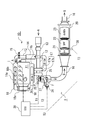
- FIG. 1 is a diagram showing a configuration of an exhaust gas purification system according to a first embodiment of the present invention.
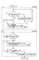
- FIG. 2 is a diagram showing a flow of the first control and the second control according to the present invention.
- FIG. 3 is a diagram showing a flow of the first control and the third control according to the present invention.
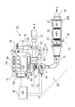
- FIG. 4 is a diagram showing a configuration of an exhaust gas purification system according to a second embodiment of the present invention.
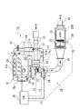
- FIG. 5 is a diagram showing a configuration of an exhaust gas purification system according to a third embodiment of the present invention.
- FIG. 6 is a diagram showing a configuration of an exhaust gas purification system according to a fourth embodiment of the present invention.
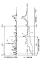
- FIG. 7 is a diagram showing an example of a time series of temperatures at the outlet position of the pre-oxidation catalyst and a time series of NOx concentration at the outlet position of the NOx purification catalyst in the example and the conventional example.
- FIG. 1 shows a configuration of an exhaust gas purification system 1 according to a first embodiment of the present invention.
- the exhaust gas purification system 1 is a system for purifying exhaust gas G of an engine (internal combustion engine) 10, and the engine 10 is an intake passage connected to an engine body 11 and an intake manifold 11 a of the engine body 11. 12, an exhaust passage 16 connected to the exhaust manifold 11 b of the engine body 11, and an EGR passage 18 connecting the exhaust passage 16 and the intake passage 12.
- an intake air amount sensor (MAF) 13 In the intake passage 12 through which the intake air A passes, an intake air amount sensor (MAF) 13, a compressor 17 a of a turbo-type supercharger 17, an intercooler 14, an intake valve 15, etc. are disposed in order from the upstream side.
- a turbine 17b of the turbocharger 17, an HC injection nozzle (fuel injection device in exhaust pipe) 24, an exhaust gas purification device 20 and the like are arranged in order from the upstream side.
- an EGR cooler 18a and an EGR valve 18b are arranged in this order from the upstream side.
- the exhaust gas purification device 20 includes a front-stage oxidation catalyst (DOC) 21, a DPF (diesel particulate filter) 22, and a NOx purification catalyst (deNOx catalyst) 23 in order from the upstream side.
- DOC front-stage oxidation catalyst
- DPF diesel particulate filter
- NOx purification catalyst deNOx catalyst
- DOC front-stage oxidation catalyst
- LNT catalyst NOx occlusion reduction type catalyst
- SCR catalyst selective reduction type catalyst
- a small pre-oxidation catalyst (Pre-DOC) 25 is disposed between the turbine 17b and the HC injection nozzle 24 in the exhaust gas purification system 1 of FIG. Hydrocarbon (HC) flowing out (slip) from the cylinder is oxidized, and the exhaust gas is heated by the oxidation heat of the hydrocarbon.
- Pre-DOC pre-oxidation catalyst
- the capacity of the small pre-oxidation catalyst 25 can generally ensure catalytic activity and efficiently oxidize HC in the range of the exhaust gas flow rate when the operating state of the engine 10 is from an idle operation state to a low load operation state.
- the capacity is set so that the SV value of the space velocity is about 100,000 / h (hr ⁇ 1 ) so as to be within the range.
- the space velocity is obtained by dividing the gas flow rate (Nm 3 / h) by the catalyst amount (m 3 ).
- the capacity of the front-stage oxidation catalyst 21 is formed with a capacity that can efficiently oxidize HC even with respect to the maximum exhaust gas flow rate in the entire range of the operating state of the engine 10, Since it is necessary to be able to cover, the pre-oxidation catalyst 21 is larger than the pre-oxidation catalyst 25.
- the pre-oxidation catalyst 25 can be made smaller than the pre-oxidation catalyst 21.
- the pre-oxidation catalyst 25 can be disposed closer to the engine body 11 than the pre-stage oxidation catalyst 21, so that the temperature of the exhaust gas G discharged from the cylinder is adjusted to the exhaust passage 16.
- the high-temperature exhaust gas G is caused to flow into the pre-oxidation catalyst 25, and the temperature of the pre-oxidation catalyst 25 is raised and maintained above the catalyst activation temperature to oxidize HC and CO. become able to.
- the first exhaust gas temperature sensor 26 is disposed upstream of the pre-oxidation catalyst 25, and the second exhaust gas temperature sensor 27 is disposed downstream of the pre-oxidation catalyst 25. Further, the third exhaust gas temperature sensor 28 is disposed between the upstream oxidation catalyst 21 and the DPF 22 of the exhaust gas purification device 20, that is, upstream of the DPF 22.
- a control device 30 called an engine control unit (ECU) that controls the engine as a whole is provided.
- the control device 30 includes temperatures T1, T2, and T3 detected by the exhaust gas temperature sensors 26, 27, and 28, a cooling water temperature Tw detected by a cooling water temperature sensor (not shown), and the rotational speed of the engine 10. Ne and load Q are input, and in-cylinder fuel injection of the engine 10 is controlled.
- the control device 30 includes the following first control, second control, and third control in the control.
- the first control is control related to activation of the pre-oxidation catalyst 25, and the first temperature T1 detected by the first exhaust gas temperature sensor 26 is preset as shown in the control flow of FIGS.
- multi-stage temperature rise injection temperature increase multi-injection
- pre-injection pilot injection
- main injection main injection
- after-injection is performed by in-cylinder fuel injection.
- the post-injection is performed in addition to the multi-stage temperature rising injection, the unburned HC supplied by the post injection is oxidized by the pre-oxidation catalyst 25, and the first 2 is a control for feedback control so that the second temperature T2 detected by the exhaust gas temperature sensor 27 becomes a preset second set temperature T2c.
- the first set temperature T1c is set to the catalyst activation temperature (approximately about 200 ° C.) of the pre-oxidation catalyst 25.
- the exhaust gas G can be heated by the multi-stage temperature rising injection until the pre-oxidation catalyst 25 is activated, and the pre-oxidation catalyst 25 can be heated by the heated exhaust gas G.
- the HC supplied by post-injection is oxidized by the catalytic action of the pre-oxidation catalyst 25 to raise the temperature of the exhaust gas G.
- the second temperature T2 can be set to the second set temperature Tc2 that meets the demands of the exhaust gas purification device 20 on the downstream side of the pre-oxidation catalyst 25.
- the second control is a control for the NOx purification catalyst 23, and as shown in the control flow of FIG. 2, the cooling water temperature Tw of the engine 10 is set to a preset cooling water temperature Twc (for example, a water temperature 40).
- Twc for example, a water temperature 40.
- the first control is performed, and the second temperature T2 can be maintained at the second set temperature T2c by the first control. If it becomes, it will be control which complete
- the second set temperature T2c is set to the catalyst activation temperature (approximately about 300 ° C.) of the NOx purification catalyst 23.
- the third control is a control for the DPF 22, and as shown in the control flow of FIG. 3, it is determined whether or not the operating state of the engine 10 is a preset low load state, and is in a low load state.
- the injection of the fuel F from the HC injection nozzle 24 is started. 3.
- the feedback control is performed so that the third temperature T3 detected by the exhaust gas temperature sensor 28 becomes the third set temperature T3c, and PM (particulate matter) collected by the DPF 22 is burned and removed during the feedback control. In this control, the multistage temperature rising injection and the post-injection are terminated when it is determined whether or not PM is burned and removed.
- the second set temperature Tc2 can be burned to a temperature at which the fuel F injected from the HC injection nozzle 24 is decomposed (approximately 300 ° C.), and the PM collected at the third set temperature Tc3 in the DPF 22 can be burned.
- Each temperature is set to approximately (approximately 500 ° C. to 600 ° C.).
- This exhaust gas purification method includes a “first control + second control” control for the NOx purification catalyst 23 as shown in FIG. 2 and a “first control + third control” as shown in FIG. And a method for performing control for regeneration of the DPF 22.
- FIG. 2 and FIG. 3 illustrate the control flow.
- the control flow of FIG. 2 and FIG. 3 is called from the upper control flow as needed when the engine 10 is started, and the steps S11 to S22 are performed. Alternatively, step S11 to step S33 are executed to return to the upper control flow, and this is repeatedly executed as necessary. When the engine 10 is stopped, the process is terminated together with the upper control flow.
- the method for the NOx purification catalyst 23 is a method for improving the NOx purification rate of the NOx purification catalyst 23 immediately after the cold start, and the cooling water temperature Tw of the engine 10 is set in advance. Implemented at lower times.
- the first set temperature T1c is the catalyst activation temperature of the pre-oxidation catalyst 25 (about 200 ° C.)
- the second set temperature T2c is the temperature at which the NOx purification catalyst 23 has a good catalyst activity (about about 300 ° C.). ) Respectively.
- This method is an exhaust gas purification method for purifying exhaust gas G exhausted from the engine 10 by passing it through an exhaust gas purification device 20 having a pre-stage oxidation catalyst 21 and a NOx purification catalyst 23.
- the pre-oxidation catalyst 25 is passed before passing through the exhaust gas purification device 20.
- the first temperature T1 detected by the first exhaust gas temperature sensor 26 on the upstream side of the exhaust gas purification device 20 in step S11 is equal to or higher than the preset first set temperature T1c. If it is low (NO), in step S12, in-cylinder combustion control, multi-stage temperature rising injection including pre-injection, main injection, and after-injection is performed. When 1 temperature T1 becomes 1st preset temperature T1c or more (YES), post injection control which performs post injection in addition to multistage temperature rising injection is implemented at Step S13.
- Steps S11 to S13 are the first control (step S10).
- step S21 it is determined whether or not the second temperature T2 can be maintained at the second set temperature T2c by the first control. If not (NO), the process proceeds to step S13. If it can return and can be maintained (YES), it will go to Step S22 and will end multi stage temperature rising injection and post injection.
- Steps S21 and S22 are the second control (step S20). Note that whether or not the second temperature T2 can maintain the second set temperature T2c is, for example, continued for a preset time or more, and the second temperature T2 is a predetermined value centered on the second set temperature T2c. It can be determined by whether or not the temperature is within the range of the temperature range.
- the multistage injection control is started to raise the temperature of the exhaust gas G.
- This multi-stage temperature rising injection is an injection control that is delayed (retarded) than the normal injection.
- the pre-injection, the main injection, and the after-injection are performed, and the in-cylinder combustion is continued to increase the in-cylinder combustion temperature Is exhausted while maintaining a high temperature, and the temperature of the exhaust gas G is raised.
- the concentration of HC and CO in the exhaust gas G increases, but since it can be adsorbed or oxidized by the pre-oxidation catalyst 25, HC and CO can be purified.
- the first temperature T1 of the exhaust gas G on the upstream side of the pre-oxidation catalyst 25 reaches the first set temperature T1c that is the catalyst activation temperature (approximately 200 ° C.) of the pre-oxidation catalyst 25, post injection is performed.
- the temperature of the pre-oxidation catalyst 25 is raised, and the second temperature T2 of the exhaust gas G downstream of the pre-oxidation catalyst 25 is a temperature at which the catalytic activity of the NOx purification catalyst 23 is good (approximately about 300 ° C.).
- the feedback control is performed so that the second set temperature T2c is as follows.
- the warm-up (warm up) of the engine 10 proceeds, the second temperature T2 of the exhaust gas G rises, and the second temperature T2 of the exhaust gas G becomes the NOx purification catalyst even if there is no multi-stage temperature rising injection or post injection.
- the temperature of the catalytic activity of 23 can be maintained at a good temperature (approximately 300 ° C.), the control is terminated.
- the method for regenerating the DPF 22 is a method for promoting DPF regeneration of the DPF 22, and is performed when the operating state of the engine 10 is a preset low load state.
- the first set temperature T1c is set to the catalyst activation temperature of the pre-stage oxidation catalyst 25, and the second set temperature T2c is set to the temperature at which the fuel F injected from the HC injection nozzle 24 is decomposed.
- This method is an exhaust gas purification method for purifying exhaust gas G exhausted from the engine 10 by passing it through an exhaust gas purification device 20 having a pre-stage oxidation catalyst 21 and a DPF 22. Before passing the purification device 20, the pre-oxidation catalyst 25 is passed.
- the first temperature T1 detected by the first exhaust gas temperature sensor 26 on the upstream side of the exhaust gas purification device 20 in step S11 is higher than the preset first set temperature T1c. If it is low (NO), in step S12, in-cylinder combustion control performs multi-stage temperature rising injection including pre-injection, main injection, and after-injection.
- step S12 in-cylinder combustion control performs multi-stage temperature rising injection including pre-injection, main injection, and after-injection.
- the first temperature T1 becomes equal to or higher than the first set temperature T1c (YES)
- post injection control is performed in which post injection is performed in addition to multi-stage temperature rising injection in step S13.
- Step S11 to S13 are the first control (step S10).
- step S31 subsequent to step S13, it is determined whether or not the second temperature T2 can maintain the second set temperature T2c by the first control. If not (NO), the process returns to step S13 and maintained. If it is possible (YES), in step S32, the fuel in the exhaust pipe is injected from the HC injection nozzle 24 provided upstream of the exhaust gas purification device 20, and the third exhaust gas temperature sensor 28 disposed upstream of the DPF 22 is used. The post-injection is feedback controlled so that the detected third temperature T3 becomes the third set temperature T3c.
- next step S33 it is determined whether or not PM (particulate matter) collected in the DPF 22 is burned and removed during the feedback control, and the PM collected in the DPF 22 is not burned and removed. If it is determined (NO), the process returns to step S32, and if it is determined that the PM collected in the DPF 22 is burned and removed (YES), the multistage temperature rising injection and the post injection are terminated in the next step S34. . Steps S31 to S34 are the third control (step S30).
- Whether or not this PM has been burned and removed depends on whether or not the regeneration time that is the total time of fuel injection in the exhaust pipe has passed a preset regeneration target time, and the differential pressure value before and after the DPF 22 is equal to or less than the differential pressure target value. It can be determined by whether or not.
- multistage temperature rising injection is started to raise the temperature of the exhaust gas G.
- concentration of HC and CO in the exhaust gas G increases, but it can be adsorbed and oxidized by the small pre-oxidation catalyst 25 to purify HC and CO.
- the first temperature T1 of the exhaust gas G upstream of the pre-oxidation catalyst 25 reaches the first set temperature T1c that is the catalyst activation temperature (approximately 200 ° C.) of the pre-oxidation catalyst 25, post injection is further added.
- the unburned HC supplied by the post injection is oxidized by the pre-oxidation catalyst 25, and the temperature of the pre-oxidation catalyst 25 and the temperature of the exhaust gas G passing therethrough are increased by the heat of oxidation.
- Feedback control is performed so that the second temperature T2 of the exhaust gas G downstream of the in-situ oxidation catalyst 25 becomes a second set temperature T2c that is a temperature at which the fuel F injected from the HC injection nozzle 24 is decomposed (approximately 300 ° C.). .
- the temperature of the DPF 22 can be raised earlier than usual, and there is an effect of preventing white smoke due to HC slip at the time of fuel injection in the exhaust pipe.
- the small pre-oxidation catalyst 25 is installed upstream of the exhaust gas purification device 20 including the front-stage oxidation catalyst 21, the DPF 22, and the NOx purification catalyst 23.
- the HC injection nozzle 24 downstream and controlling the multistage temperature rising injection, post injection, fuel injection in the exhaust pipe, etc., the HC during the multistage temperature rising injection is adsorbed and oxidized by the pre-oxidation catalyst 25.
- HC slip can be prevented and multi-stage temperature rising injection can be performed from the cold time, so that the effect of improving the NOx purification rate of the exhaust gas at the cold time can be obtained.
- the exhaust gas purification device 20A is configured by disposing a pre-stage oxidation catalyst 21, a NOx purification catalyst 23, and a DPF 22 from the upstream side. That is, it differs from the exhaust gas purification system 1 of the first embodiment in that the NOx purification catalyst 23 is arranged on the upstream side of the DPF 22.
- Others are the same as the exhaust gas purification system 1 and the exhaust gas purification method of the first embodiment, including that the control device 30 includes the first control, the second control, and the third control. The same effects can be obtained.
- an exhaust gas purification system 1B according to a third embodiment shown in FIG. 5 will be described.
- an exhaust gas purification device 20B is configured by arranging a pre-stage oxidation catalyst 21 and a NOx purification catalyst 23 from the upstream side. That is, the exhaust gas purification system 1 of the first embodiment is configured such that there is no DPF 22 and the control device 30 includes the first control and the second control, but does not include the third control. Is different. Other configurations are the same as those of the exhaust gas purification system 1 and the exhaust gas purification method of the first embodiment, and the effects of the first control and the second control can be obtained.
- the exhaust gas purification device 20C is configured by arranging the pre-stage oxidation catalyst 21 and the DPF 22 from the upstream side. That is, in the exhaust gas purification system 1 of the first embodiment, the NOx purification catalyst 23 is not included, and the control device 30 includes the first control and the third control, but does not include the second control. The point which is comprised is different. Other configurations are the same as those of the exhaust gas purification system 1 and the exhaust gas purification method of the first embodiment, and the effects of the first control and the third control can be obtained.
- FIG. 7 shows experimental results of Example A in which the first control and the second control are performed and Comparative Example B in which the first control and the second control are not performed in the exhaust gas purification system 1 of the first embodiment.
- the catalyst temperature (° C.) in the lower stage of FIG. 7 is the temperature at the outlet position of the pre-oxidation catalyst (Pre-DOC) 25.
- 900 s (seconds) was required to reach 200 ° C.
- Example A it reached 200 ° C. in 300 s, and it can be seen that the temperature increase promotion effect of the exhaust gas G by the pre-oxidation catalyst 25 and the first control is great.
- the NOx concentration at the catalyst outlet in the upper stage of FIG. 7 is the NOx concentration (ppm) at the outlet position of the NOx purification catalyst 23, and compared with Comparative Example B without multistage temperature rising injection, there is multistage temperature rising injection. In Example A, it can be seen that the NOx concentration is significantly reduced.
- the exhaust gas purification system and the exhaust gas purification method of the present invention improve the low-temperature characteristics of an exhaust gas purification device including a pre-stage oxidation catalyst (DOC) and at least one of a NOx purification catalyst or a DPF, and reduce the low-temperature exhaust gas.
- DOC pre-stage oxidation catalyst
- the NOx purification characteristics of the NOx purification catalyst can be improved and the generation of white smoke due to HC slips during NOx purification, NOx regeneration and PM regeneration at low temperatures can be prevented. It can be used as an engine exhaust gas purification system and an exhaust gas purification method.
- Exhaust gas purification system 10 Engine (internal combustion engine) 16 Exhaust passages 20, 20A, 20B, 20C Exhaust gas purification device 21 Pre-stage oxidation catalyst (DOC) 22 DPF 23 NOx purification catalyst 24 HC injection nozzle (exhaust pipe fuel injection device) 25 Pre-oxidation catalyst (Pre-DOC) 26 First exhaust gas temperature sensor 27 Second exhaust gas temperature sensor 28 Third exhaust gas temperature sensor 30 Control device (ECU) F Hydrocarbon (HC: Light oil: Fuel) G Exhaust gas T1 Exhaust gas first temperature T2 Exhaust gas second temperature T3 Exhaust gas third temperature T1c First set temperature T2c Second set temperature T3c Third set temperature Tw Cooling water temperature Twc Cooling water set temperature
Landscapes
- Engineering & Computer Science (AREA)
- Chemical & Material Sciences (AREA)
- Combustion & Propulsion (AREA)
- Mechanical Engineering (AREA)
- General Engineering & Computer Science (AREA)
- Chemical Kinetics & Catalysis (AREA)
- Health & Medical Sciences (AREA)
- Toxicology (AREA)
- Materials Engineering (AREA)
- Biomedical Technology (AREA)
- Environmental & Geological Engineering (AREA)
- Analytical Chemistry (AREA)
- General Chemical & Material Sciences (AREA)
- Oil, Petroleum & Natural Gas (AREA)
- Processes For Solid Components From Exhaust (AREA)
- Exhaust Gas After Treatment (AREA)
- Electrical Control Of Air Or Fuel Supplied To Internal-Combustion Engine (AREA)
Abstract
内燃機関(11)の排気ガス(G)を、前置酸化触媒(25)を通過させてから排気ガス浄化装置(20)を通過させると共に、排気ガス浄化装置(20)の上流側の排気ガス(G)の第1温度(T1)が第1設定温度(T1c)よりも低い場合は、多段昇温噴射を行い、第1温度(T1)が第1設定温度(T1c)以上になったら多段昇温噴射に加えてポスト噴射を行って、排気ガス浄化装置(20)の下流側の排気ガス(G)の第2温度(T2)が第2設定温度(T2c)になるようにポスト噴射をフィードバック制御する。これにより、前段酸化触媒(21)を備えた排気ガス浄化装置(20)の上流に前置酸化触媒(25)を設置すると共に、多段昇温噴射とポスト噴射における燃料噴射を制御して、低温時のNOx浄化特性の改善や、低温時のDPF再生の際のHCスリップによる白煙の発生等の防止を図る。
Description
本発明は、前段酸化触媒と、少なくともNOx浄化触媒かDPFの一方を備えた排気ガス浄化装置の低温特性を改善して、低温時におけるNOx浄化率を向上したり、白煙の発生を防止したりすることができる排気ガス浄化システム及び排気ガス浄化方法に関する。
ディーゼルエンジンや一部のガソリンエンジン等の内燃機関においては、排気ガス中のNOx(窒素酸化物)やPM(粒子状物質)を低減するために、NOx浄化触媒(deNOx触媒)やDPF(ディーゼルパティキュレートフィルタ)が使用されている。
このNOx浄化触媒には、リーンNOxトラップ触媒(LNT触媒)と選択還元型触媒(SCR触媒)等があり、このリーンNOxトラップ触媒のひとつにNOx吸蔵還元型触媒がある。このNOx吸蔵還元型触媒は、NOxを吸蔵するNOx吸蔵材と、貴金属を担持した触媒であり、流入する排気ガスの空燃比がリーン(酸素過多)状態であって雰囲気中の酸素(O2)濃度が高い場合には、排気ガス中の一酸化窒素(NO)が貴金属上で酸化されて二酸化窒素(NO2)となり、この二酸化窒素はバリウム(Ba)等のNOx吸蔵材と結合して硝酸塩(Ba2NO4)等になり吸蔵される。
また、このNOx吸蔵還元型触媒に流入する排気ガスの空燃比が理論空燃比やリッチ(低酸素濃度)状態になって、雰囲気中の酸素濃度が低下すると、NOx吸蔵材は一酸化炭素(CO)と結合し、硝酸塩が分解して二酸化窒素が放出される。この放出された二酸化窒素は貴金属の三元機能により排気ガス中に含まれている未燃炭化水素(HC)や一酸化炭素等で還元されて窒素(N2)となり、排気ガス中の諸成分は、二酸化炭素(CO2),水(H2O),窒素等の無害な物質として大気中に放出される。
そのため、NOx吸蔵還元型触媒を備えた排気ガス浄化システムでは、NOx吸蔵能力が飽和に近くなると、排気ガスの空燃比をリッチ状態にして、流入する排気ガスの酸素濃度を低下させる制御、即ち、NOx吸蔵能力回復用のリッチ制御を行うことにより、吸収したNOxを放出させて、この放出されたNOxを貴金属により窒素に還元させるNOx再生操作を行っている。
このNOx吸蔵還元型触媒を始め、一般的に触媒は活性化温度以上にならないとその触媒作用が活性化しないので、触媒が活性化しない低温時においては触媒反応が促進されず、NOx吸蔵還元型触媒や選択還元型触媒等のNOx浄化触媒ではNOx浄化率が低くなってしまうという問題がある。
この低温時の触媒におけるNOx浄化率を向上させるために、ディーゼルエンジンの排気ガス処理においても排気ガスの昇温制御が検討されている。この昇温制御は、プレ噴射(パイロット噴射)、メイン噴射(主噴射)、アフター噴射等の組み合わせである多段昇温噴射(マルチ噴射)により、ピストンの上死点以降の膨張行程の筒内(シリンダ内)の燃焼温度を高温に保って、排気ガス温度を昇温させる制御である。この昇温制御により、早期に排気ガス温度を昇温して、排気通路に配設された排気ガス浄化装置の触媒の活性を早めることができる。
また、排気ガス中のPMを捕集するDPFを備えた排気ガス浄化システムでは、PM捕集量がDPFの捕集可能な量(飽和状態の量)に近くなると、このPM捕集能力を回復するために、捕集したPMが燃焼を開始する温度以上にDPFの温度を昇温して、PMを燃焼除去するPM再生制御を行っている。このDPFの昇温に際しては、DPFに流入する排気ガスを昇温して、高温の排気ガスによりDPFを昇温する昇温制御が行われている。
しかしながら、冷間時の排気ガスの昇温制御では、多段昇温噴射の昇温制御で筒内に噴射された燃料の殆どは筒内で燃焼するが、燃え残りの未燃炭化水素(HC)が、そのまま排気ガス浄化装置を通り抜けてしまう場合がある。つまり、排気ガスの昇温制御を行った場合に、排気通路に設けた触媒の温度が触媒活性化温度以下である場合には、筒内から排出された未燃炭化水素が排気通路の最後部のテールパイプに到達して大気中に流出(スリップ)して大気中に放出されてしまうという問題がある。
このHCスリップは、NOx浄化触媒における冷間時の場合やNOx吸蔵還元型触媒におけるNOx再生の場合だけではなく、エンジンが低負荷の時のDPFにおけるPMを燃焼除去するPM再生の場合にも同様に発生する可能性がある。
例えば、日本出願特開2010-31833号公報に記載されているように、このHC(炭化水素)の大気中への放出を低減するために、前段酸化触媒(DOC)とDPFの構成で、アーリーポスト噴射によるDOC昇温と、レイトポスト噴射によって供給され未燃成分のDOCにおける酸化反応熱によるDPF昇温とを行う排気ガス浄化装置で、目標レイトポスト噴射量に対して、一定時間の遅れを持たせることで、レイトポスト噴射の噴射量の急激な上昇を抑えてHCスリップを防止するディーゼルエンジンの排気浄化装置が提案されている。
しかしながら、このようなDOCを使用している場合には、排気ガス中の未燃成分(未燃HC)を酸化するDOCは、内燃機関の運転領域全体をカバーする必要があるため、小型化が困難であり、エンジン本体の近くに設置することに限界がある。また、排気管内直接噴射を使用する場合には、噴射した燃料の気化に一定の時間が必要であるため、また、HC噴射弁ノズル(排気管内直接噴射装置)とDOCとの間隔が狭いと、DOCの前面で燃料の部分酸化(クラッキング)により煤が発生し、閉塞が生じる場合があるため、HC噴射ノズルとDOCとの間隔を大きく、例えば、1m以上にする必要が生じる。
これらの理由からも、DOCをエンジン本体の近くに配置することができないので、筒内から排出された排気ガスがDOCに到達する前に放熱により温度が低くなってしまう。そのため、低温時においては、排気ガス中の未燃HCをDOCで十分に酸化することができず、HCスリップが発生してしまう。
この低温時におけるHCスリップの対策として、例えば、日本出願特開2011-163250号公報に記載されているように、前段酸化触媒(DOC)とDPFの構成で、アーリーポスト噴射によるDOC昇温と、レイトポスト噴射によって供給され未燃成分のDOCにおける酸化反応熱によるDPF昇温とを行う排気ガス浄化装置において、アーリーポスト噴射後、DOCが活性温度に達するまでの間に、未燃HC成分が外部に多量に放出されるのを防止するために、アーリーポスト噴射開始まで、オイル循環ポンプの動力を増大させることでディーゼル機関の負荷を増大させて、DOC昇温ステージにおける排気ガス昇温勾配を増大させて、DOCの活性化を促進し、HCスリップを低減する内燃機関の排気ガス処理方法及び装置が提案されている。しかしながら、この排気ガス処理方法及び装置では、低温始動時に、内燃機関の筒内の温度を昇温させるためにディーゼル機関の負荷を増大するので、燃費が悪化するおそれがある。
本発明は、上記の問題を解決するためになされたものであり、その目的は、前段酸化触媒(DOC)と、少なくともNOx浄化触媒かDPFの一方を備えた排気ガス浄化装置の低温特性を改善できて、低温の排気ガスに対するNOx浄化触媒のNOx浄化特性を改善したり、低温時のNOx浄化やNOx再生やPM再生時におけるHCスリップによる白煙の発生を防止したりすることができる排気ガス浄化システム及び排気ガス浄化方法を提供することにある。
上記のような目的を達成するための排気ガス浄化システムは、内燃機関の排気通路に、前段酸化触媒と、少なくともNOx浄化触媒かDPFの一方を備えた排気ガス浄化装置を設けると共に、前記内燃機関の運転を制御する制御装置を備えた排気ガス浄化システムにおいて、前記排気ガス浄化装置の上流側の前記排気通路に、第1排気ガス温度センサと前置酸化触媒と第2排気ガス温度センサを上流側から順に配置して構成し、前記制御装置を、前記第1排気ガス温度センサで検出した第1温度が予め設定した第1設定温度よりも低い場合は、筒内燃焼制御で多段昇温噴射を行い、前記第1温度が前記第1設定温度以上になったら前記多段昇温噴射に加えてポスト噴射を行い、前記第2排気ガス温度センサで検出した第2温度が予め設定した第2設定温度になるように前記ポスト噴射をフィードバック制御する第1制御を実施するように構成する。
この構成によれば、前段酸化触媒(DOC)と、少なくともNOx浄化触媒かDPFの一方を備えた排気ガス浄化装置よりも、上流側の筒内(シリンダ内)の近くに配置される前置酸化触媒(Pre-DOC)に、前段酸化触媒に流入する排気ガスより高温の排気ガスを流入させて活性化し易く構成したので、この前置酸化触媒により、筒内の多段昇温噴射によって筒内から流出する排気ガス中の未燃HCを効率良く酸化でき、HCスリップを防止しながら、前置酸化触媒で酸化されるHCの酸化熱により排気ガス、前段酸化触媒、NOx浄化触媒、DPF等を効率良く昇温でき、NOx浄化率の向上やDPF再生の効率化を図ることができる。
この前置酸化触媒は、主に筒内から排出された直後のHC、COを酸化するためのもので、内燃機関の運転状態がアイドル状態や低負荷の排気ガス温度が低く、また、排気ガスの量が少ない場合のみ、排気ガスの昇温機能を果たすことができればよいので、小型化できる。例えば、容量について、空間速度のSV値が100,000/h(hr-1)程度となるような小型の酸化触媒で形成することができる。
この前置酸化触媒は小型にすることができるので、内燃機関のエンジン本体に極力近づけて設置することができる。なお、この前置酸化触媒だけでは、内燃機関の運転領域全域をカバーできず、カバーできない範囲は、前段酸化触媒(DOC)でカバーすることになる。そのため、排気ガス浄化装置の前段酸化触媒も必要となる。
そして、この構成では、まず、筒内で多段昇温噴射やポスト噴射を行い、筒内から排出される排気ガス中のHCを前置酸化触媒で酸化して排気ガスの温度を昇温する。つまり、多段昇温噴射で前置酸化触媒を早期に触媒活性化温度以上に昇温して、この昇温後はポスト噴射により供給されたHCを前置酸化触媒で酸化して排気ガスを昇温する。これにより、排気ガス浄化装置の前段酸化触媒を昇温することができる。
この場合、エンジン本体の近い位置に設置可能で、かつ、小型で熱容量の小さい前置酸化触媒は非常に早期に昇温して、触媒活性化温度以上になるので、HCを低温始動時でも非常に早い時期から効率良く酸化することができる。なお、ここでいう多段昇温噴射は、プレ噴射とメイン噴射とアフター噴射とからなる筒内燃料噴射である。
上記の排気ガス浄化システムにおいて、前記NOx浄化触媒を備えて前記排気ガス浄化装置を構成し、前記制御装置において、前記第1設定温度を前記前置酸化触媒の触媒活性化温度に、前記第2設定温度を前記NOx浄化触媒の触媒活性が良好な温度にそれぞれ設定すると共に、前記制御装置を、前記内燃機関の冷却水の温度が予め設定した冷却水用設定温度より低い時に、前記第1制御を実施し、前記第1制御の実施により、前記第2温度が前記第2設定温度を維持できるようになったら、前記多段昇温噴射と前記ポスト噴射を終了する制御を実施するように構成する。
なお、このNOx浄化触媒の触媒活性が良好な温度とは、NOx浄化触媒の触媒活性化温度以上で、NOx浄化率が比較的高い温度範囲の中の一つの温度である。例えば、NOx浄化率が最も高い温度や、NOx浄化率が許容範囲にあり、かつ、NOx浄化触媒の寿命の観点から最も好ましい温度等である。
この構成によれば、内燃機関の冷間始動時において、冷却水温度で冷間状態か暖機状態かを判定しながら、冷間状態では、前置酸化触媒と第1制御により、多段昇温噴射によって発生する可能性のあるHCスリップを防止できるので、冷間時から多段昇温噴射が可能になり、冷間時における第1制御で、排気ガス、前段酸化触媒、及びNOx浄化触媒の早期昇温ができ、NOx浄化触媒におけるNOx浄化率を向上できる。
また、上記の排気ガス浄化システムにおいて、前記DPFを備えて前記排気ガス浄化装置を構成すると共に、前記DPFより上流側の前記排気通路に、排気管内燃料噴射装置と前記DPFに流入する排気ガスの温度を検出する第3排気ガス温度センサを配置して構成し、前記制御装置において、前記第1設定温度を前記前置酸化触媒の触媒活性化温度に、第2設定温度を前記排気管内燃料噴射装置から噴射される燃料が分解する温度に、第3設定温度を前記DPFに捕集された粒子状物質が燃焼可能となる温度に、それぞれ設定すると共に、前記制御装置を、前記内燃機関の低負荷時に、前記第1制御を実施し、前記第1制御の実施により、前記第2温度が前記第2設定温度を維持できるようになったら、前記排気管内燃料噴射装置からの燃料噴射を開始し、前記第3排気ガス温度センサで検出した第3温度が前記第3設定温度になるように前記ポスト噴射をフィードバック制御し、該フィードバック制御の実施中に前記DPFに捕集された粒子状物質が燃焼除去されたか否かを判定し、前記DPFに捕集された粒子状物質が燃焼除去されたと判定したときに、前記多段昇温噴射と前記ポスト噴射を終了する制御を実施するように構成する。
この構成によれば、前置酸化触媒と第1制御により、内燃機関の運転状態が低負荷状態である場合のDPFのPM再生時に、多段昇温噴射によって発生する可能性のあるHCスリップを防止できるので、低負荷時においても、多段昇温噴射が可能になり、第1制御により排気ガスの温度を排気管燃料噴射装置により噴射する燃料が分解する温度に早期に到達させることができて、HCスリップの防止効果を得ることができ、それと共に、DPFのPM再生時の昇温の促進効果を得て、DPFを早期昇温でき、PMを効率良く除去できる。
また、この前置酸化触媒は、排気管内燃料噴射装置と組み合わせた場合により効果が大きくなる。つまり、噴射した燃料を気化させるために一定の時間が必要であるため、排気管内燃料噴射装置と前段酸化触媒との間隔を広く、例えば、1m以上取る必要が生じ、前段酸化触媒がエンジン本体と離れた位置に配置されることになるが、排気管内燃料噴射装置よりも上流側に配置する前置酸化触媒は、エンジン本体に近く、筒内から排出される高温の排気ガスが流入するので、排気ガス浄化装置に流入する排気ガスの昇温が必要な時に、前置酸化触媒は早期に触媒活性化温度以上に昇温でき、ポスト噴射によって供給されるHCを早期に酸化できるようになるため、排気ガスを迅速に昇温できる。
そして、上記の目的を達成するための排気ガス浄化方法は、内燃機関から排出される排気ガスを、前段酸化触媒と、少なくともNOx浄化触媒かDPFの一方を備えた排気ガス浄化装置を通過させて浄化する排気ガス浄化方法において、前記排気ガスを、前置酸化触媒を通過させてから前記排気ガス浄化装置を通過させると共に、前記排気ガス浄化装置の上流側の第1排気ガス温度センサで検出した第1温度が予め設定した第1設定温度よりも低い場合は、筒内燃焼制御で多段昇温噴射を行い、前記第1温度が前記第1設定温度以上になったら前記多段昇温噴射に加えてポスト噴射を行い、前記排気ガス浄化装置の下流側の第2排気ガス温度センサで検出した温度が予め設定した第2設定温度になるように前記ポスト噴射をフィードバック制御する第1制御を実施することを特徴とする方法である。
この方法によれば、前段酸化触媒と、少なくともNOx浄化触媒かDPFの一方を備えた排気ガス浄化装置よりも、上流側の筒内(シリンダ内)の近くに配置される前置酸化触媒に、前段酸化触媒に流入する排気ガスより高温の排気ガスを流入させて活性化し易く構成したので、この前置酸化触媒により、筒内の多段昇温噴射によって筒内から流出する排気ガス中の未燃HCを効率良く酸化でき、HCスリップを防止しながら、前置酸化触媒で酸化されるHCの酸化熱により排気ガス、前段酸化触媒、NOx浄化触媒、DPF等を効率良く昇温でき、NOx浄化率の向上やDPF再生の効率化を図ることができる。
上記の排気ガス浄化方法において、前記排気ガスを、前記NOx浄化触媒を備えた前記排気ガス浄化装置を通過させると共に、前記第1設定温度を前記前置酸化触媒の触媒活性化温度に、前記第2設定温度を前記NOx浄化触媒の触媒活性が良好な温度にそれぞれ設定し、かつ、前記内燃機関の冷却水の温度が予め設定された冷却水用設定温度より低い時に前記第1制御を実施し、前記第1制御の実施により、前記第2温度が前記第2設定温度を維持できるようになったら、前記多段昇温噴射と前記ポスト噴射を終了する。
この方法によれば、内燃機関の冷間始動時において、冷却水温度で冷間状態か暖機状態かを判定しながら、冷間状態では、前置酸化触媒と第1制御により、多段昇温噴射によって発生する可能性のあるHCスリップを防止できるので、冷間時から多段昇温噴射が可能になり、冷間時における第1制御で、排気ガス、前段酸化触媒、及びNOx浄化触媒の早期昇温ができ、NOx浄化触媒におけるNOx浄化率を向上できる。
また、上記の排気ガス浄化方法において、前記排気ガスを、前記DPFを備えた前記排気ガス浄化装置を通過させると共に、前記第1設定温度を前記前置酸化触媒の触媒活性化温度に、前記第2設定温度を前記排気管内燃料噴射装置から噴射される燃料が分解する温度に、第3設定温度を前記DPFに捕集された粒子状物質が燃焼可能となる温度に、それぞれ設定し、かつ、前記内燃機関の低負荷時に前記第1制御を実施すると共に、前記第1制御の実施により、前記第2温度が前記第2設定温度を維持できるようになったら、前記排気ガス浄化装置の上流に設けた前記排気管内燃料噴射装置から燃料噴射を開始し、前記DPFの上流に配置した前記第3排気ガス温度センサで検出した第3温度が前記第3設定温度になるように前記ポスト噴射をフィードバック制御し、該フィードバック制御の実施中に前記DPFに捕集された粒子状物質が燃焼除去されたか否かを判定し、前記DPFに捕集された粒子状物質が燃焼除去されたと判定したときに、前記多段昇温噴射と前記ポスト噴射を終了する。
この方法によれば、前置酸化触媒と第1制御により、内燃機関の運転状態が低負荷状態である場合のDPFのPM再生時に、多段昇温噴射によって発生する可能性のあるHCスリップを防止できるので、低負荷時においても、多段昇温噴射が可能になり、第1制御により排気ガスの温度を排気管内燃料噴射装置により噴射する燃料が分解する温度に早期に到達させることができて、HCスリップの防止効果を得ることができ、それと共に、DPFのPM再生時の昇温の促進効果を得て、DPFを早期昇温でき、PMを効率良く除去できる。
本発明に係る排気ガス浄化システム及び排気ガス浄化方法によれば、前段酸化触媒と、少なくともNOx浄化触媒かDPFの一方を備えた排気ガス浄化装置の上流に前置酸化触媒を設置する配置を採用すると共に、第1制御で、多段昇温噴射とポスト噴射を制御することにより、排気ガスが低温のときにおいて、排気ガス、前段酸化触媒、NOx浄化装置、DPF等の昇温を早期に達成できて、NOx浄化やNOx再生やDPF再生を効率良く行うことができる。
以下、本発明に係る実施の形態の排気ガス浄化システム及び排気ガス浄化方法について、図面を参照しながら説明する。
図1に、本発明に係る第1の実施の形態の排気ガス浄化システム1の構成を示す。
この排気ガス浄化システム1は、エンジン(内燃機関)10の排気ガスGを浄化するためのシステムであり、このエンジン10は、エンジン本体11とこのエンジン本体11の吸気マニホールド11aに接続される吸気通路12と、エンジン本体11の排気マニホールド11bに接続される排気通路16と、排気通路16と吸気通路12とを接続するEGR通路18を有して構成されている。
吸気Aが通過する吸気通路12には、上流側から順に、吸気量センサ(MAF)13、ターボ式過給器17のコンプレッサ17a、インタークーラ14、吸気弁15等が配設されており、また、排気ガスGが通過する排気通路16には、上流側から順に、ターボ式過給器17のタービン17b、HC噴射ノズル(排気管内燃料噴射装置)24、排気ガス浄化装置20等が配設されている。更に、EGRガスGeが通過するEGR通路18には、上流側から順に、EGRクーラー18aとEGR弁18bが配設されている。
また、排気ガス浄化装置20は、上流側から順に、前段酸化触媒(DOC)21とDPF(ディーゼルパティキュレートフィルタ)22とNOx浄化触媒(deNOx触媒)23を備えて構成される。このNOx浄化触媒23としては、NOx吸蔵還元型触媒(LNT触媒)や選択還元型触媒(SCR触媒)等を用いることができる。
本発明では、この図1の排気ガス浄化システム1において、タービン17bとHC噴射ノズル24との間に小型の前置酸化触媒(Pre-DOC)25を配置し、この前置酸化触媒25により、筒内から流出(スリップ)してくる炭化水素(HC)を酸化し、この炭化水素の酸化熱により排気ガスを昇温する。
この小型の前置酸化触媒25の容量は、エンジン10の運転状態がアイドル運転状態から低負荷運転状態の排気ガスの流量の範囲で、一般的に触媒活性が確保でき、効率良くHCを酸化できる範囲となるような、空間速度のSV値が、100,000/h(hr-1)程度となるような容量にする。なお、この空間速度とは、ガス流速(Nm3/h)を触媒量(m3)で割り算したものである。
一方、前段酸化触媒21の容量は、エンジン10の運転状態の全範囲において、最大の排気ガスの流量に対しても効率良くHCを酸化できるような容量で形成して、運転状態の全範囲をカバーできるようにする必要があるので、この前段酸化触媒21は前置酸化触媒25に比べて大きくなる。
逆に言えば、前置酸化触媒25の方は前段酸化触媒21よりも小型化できる。そして、この小型化により、前置酸化触媒25を、前段酸化触媒21よりもエンジン本体11に近い側に配設できるようになるので、筒内から排出される排気ガスGの温度が排気通路16の放熱により低下する前に、高温の排気ガスGを前置酸化触媒25に流入させて、前置酸化触媒25の温度を触媒活性化温度以上に昇温及び維持して、HCやCOを酸化できるようになる。
また、第1排気ガス温度センサ26を前置酸化触媒25の上流側に、第2排気ガス温度センサ27を前置酸化触媒25の下流側にそれぞれ配置する。また、第3排気ガス温度センサ28を排気ガス浄化装置20の前段酸化触媒21とDPF22の間、即ち、DPF22の上流に配置する。
そして、エンジン全般の制御を行うエンジンコントロールユニット(ECU)と呼ばれる制御装置30が設けられる。この制御装置30は、各排気ガス温度センサ26、27、28で検出された温度T1,T2,T3と冷却水温度センサ(図示しない)で検出された冷却水温度Twと、エンジン10の回転速度Neや負荷Qを入力して、エンジン10の筒内燃料噴射を制御するように構成される。
この制御装置30は、その制御に、次の第1制御と第2制御と第3制御を含んで構成される。第1制御は、前置酸化触媒25の活性化に関係する制御であり、図2及び図3の制御フローに示すように、第1排気ガス温度センサ26で検出した第1温度T1が予め設定した第1設定温度T1cよりも低い場合は、筒内燃料噴射でプレ噴射(パイロット噴射)とメイン噴射(主噴射)とアフター噴射とからなる多段昇温噴射(昇温用マルチ噴射)を行う。そして、第1温度T1が第1設定温度Tc1以上になったら多段昇温噴射に加えてポスト噴射を行って、ポスト噴射で供給された未燃HCを前置酸化触媒25で酸化させて、第2排気ガス温度センサ27で検出した第2温度T2が予め設定した第2設定温度T2cになるようにフィードバック制御する制御である。
この第1制御では、第1設定温度T1cを前置酸化触媒25の触媒活性化温度(概ね200℃程度)に設定する。これにより、前置酸化触媒25が活性化するまで多段昇温噴射で排気ガスGを昇温して、この昇温した排気ガスGで前置酸化触媒25を昇温することができ、前置酸化触媒25が触媒活性化温度以上に昇温してからは、ポスト噴射によって供給されるHCを前置酸化触媒25の触媒作用で酸化して排気ガスGを昇温し、排気ガスGの第2温度T2を、前置酸化触媒25の下流側の排気ガス浄化装置20の要望に合った第2設定温度Tc2にすることができる。
また、第2制御は、NOx浄化触媒23用の制御であり、図2の制御フローに示すように、エンジン10の冷却水の温度Twが予め設定した冷却水用設定温度Twc(例えば、水温40℃)より低いか否かを判定し、低いと判定したときには冷間状態であるとして、第1制御を実施すると共に、第1制御により、第2温度T2が第2設定温度T2cを維持できるようになったら、冷間状態から暖機状態になったとして、多段昇温噴射とポスト噴射を終了する制御である。この第2制御では、第2設定温度T2cをNOx浄化触媒23の触媒活性化温度(概ね300℃程度)に設定する。
また、第3制御は、DPF22用の制御であり、図3の制御フローに示すように、エンジン10の運転状態が予め設定した低負荷状態であるか否かを判定し、低負荷状態であると判定したときに第1制御を実施すると共に、第1制御により、第2温度T2が第2設定温度T2cを維持できるようになったら、HC噴射ノズル24から燃料Fの噴射を開始し、第3排気ガス温度センサ28で検出した第3温度T3が第3設定温度T3cになるようにフィードバック制御し、このフィードバック制御の実施中にDPF22に捕集されたPM(粒子状物質)が燃焼除去されたか否かを判定し、PMが燃焼除去されたと判定したときに、多段昇温噴射とポスト噴射を終了する制御である。この第3制御では、第2設定温度Tc2をHC噴射ノズル24から噴射される燃料Fが分解する温度(概ね300℃程度)に、第3設定温度Tc3をDPF22に捕集されたPMが燃焼可能となる温度(概ね500℃~600℃程度)に、それぞれ設定する。
次に、上記の排気ガス浄化システム1における排気ガス浄化方法について説明する。この排気ガス浄化方法には、図2に示すような「第1制御+第2制御」のNOx浄化触媒23用の制御を行う方法と、図3に示すような「第1制御+第3制御」のDPF22の再生用の制御を行う方法とがある。図2及び図3にその制御フローを例示するが、この図2及び図3の制御フローは、エンジン10の始動と共に、必要に応じて、上位の制御フローから呼ばれて、ステップS11~ステップS22、又は、ステップS11~ステップS33を実施して、上位の制御フローに戻り、これを必要に応じて繰り返し実行し、エンジン10が停止すると、上位の制御フローと共に終了するものとして示してある。
NOx浄化触媒23用の方法は、冷間始動直後のNOx浄化触媒23のNOx浄化率を向上させるための方法であり、エンジン10の冷却水の温度Twが予め設定された冷却水用設定温度Twcより低い時に実施される。この方法では、第1設定温度T1cを前置酸化触媒25の触媒活性化温度(概ね200℃程度)に、第2設定温度T2cをNOx浄化触媒23の触媒活性が良好な温度(概ね300℃程度)にそれぞれ設定する。
この方法は、エンジン10から排出される排気ガスGを、前段酸化触媒21と、NOx浄化触媒23を備えた排気ガス浄化装置20を通過させて浄化する排気ガス浄化方法であり、排気ガスGを、排気ガス浄化装置20を通過させる前に、前置酸化触媒25を通過させる。
それと共に、図2に示すような制御フローに従って、ステップS11で排気ガス浄化装置20の上流側の第1排気ガス温度センサ26で検出した第1温度T1が予め設定した第1設定温度T1c以上であるか否かを判定し、低い場合は(NO)、ステップS12で、筒内燃焼制御においてプレ噴射とメイン噴射とアフター噴射とからなる多段昇温噴射を実施し、ステップS11の判定で、第1温度T1が第1設定温度T1c以上になった場合は(YES)、ステップS13で多段昇温噴射に加えてポスト噴射を行うポスト噴射制御を実施する。このポスト噴射制御では、排気ガス浄化装置20の下流側の第2排気ガス温度センサ27で検出した温度T2が予め設定した第2設定温度T2cになるようにポスト噴射をフィードバック制御する。このステップS11からステップS13が第1制御(ステップS10)となる。
そして、ステップS13の次のステップS21で、第1制御により、第2温度T2が第2設定温度T2cを維持できるようになったか否かを判定し、維持できない場合は(NO)、ステップS13に戻り、維持できるようになったら(YES)、ステップS22に行き、多段昇温噴射とポスト噴射を終了する。このステップS21とS22が第2制御(ステップS20)となる。なお、第2温度T2が第2設定温度T2cを維持できているか否かは、例えば、予め設定した時間以上継続して、第2温度T2が第2設定温度T2cを中心とする予め設定した所定の温度幅の範囲内にあるか否か等によって判定することができる。
つまり、エンジン10の冷却水の温度Twが冷却水用設定温度(例えば、40℃)Twc以下の冷間時に、多段噴射制御を開始して排気ガスGを昇温する。この多段昇温噴射は通常噴射よりも遅延(リタード)した噴射制御で、上死点後に連続して、プレ噴射、メイン噴射、アフター噴射を行い、筒内の燃焼を継続させて筒内燃焼温度を高温に保ったまま排気して、排気ガスGの温度を昇温する。この多段昇温噴射時は排気ガスG中のHC,COの濃度が高くなるが、前置酸化触媒25により吸着又は酸化できるのでHC,COを浄化することができる。
また、前置酸化触媒25の上流側の排気ガスGの第1温度T1が前置酸化触媒25の触媒活性化温度(概ね200℃程度)である第1設定温度T1cに達したら、ポスト噴射を更に追加して、前置酸化触媒25の昇温を行い、前置酸化触媒25の下流の排気ガスGの第2温度T2がNOx浄化触媒23の触媒活性が良好な温度(概ね300℃程度)である第2設定温度T2cになるように、フィードバック制御する。
そして、エンジン10の暖機(暖気)が進行して、排気ガスGの第2温度T2が上昇し、多段昇温噴射やポスト噴射が無くても排気ガスGの第2温度T2がNOx浄化触媒23の触媒活性が良好な温度(概ね300℃程度)を保てるようになったら制御を終了する。
この方法によれば、通常よりも早期に、NOx浄化触媒23を昇温して、NOx浄化率を向上させることができるというメリットがある。
一方、DPF22の再生用の方法は、DPF22のDPF再生を促進するための方法であり、エンジン10の運転状態が予め設定された低負荷状態であるときに実施される。この方法では、第1設定温度T1cを前段酸化触媒25の触媒活性化温度に、第2設定温度T2cをHC噴射ノズル24から噴射される燃料Fが分解する温度にそれぞれ設定する。
この方法は、エンジン10から排出される排気ガスGを、前段酸化触媒21と、DPF22を備えた排気ガス浄化装置20を通過させて浄化する排気ガス浄化方法であり、排気ガスGを、排気ガス浄化装置20を通過させる前に、前置酸化触媒25を通過させる。
それと共に、図3に示すような制御フローに従って、ステップS11で排気ガス浄化装置20の上流側の第1排気ガス温度センサ26で検出した第1温度T1が予め設定した第1設定温度T1cよりも低いか否かを判定し、低い場合は(NO)、ステップS12で、筒内燃焼制御でプレ噴射とメイン噴射とアフター噴射とからなる多段昇温噴射を実施し、ステップS11の判定で、第1温度T1が第1設定温度T1c以上になった場合に(YES)、ステップS13で多段昇温噴射に加えてポスト噴射を行うポスト噴射制御を実施する。このポスト噴射では、排気ガス浄化装置20の下流側の第2排気ガス温度センサ27で検出した第2温度T2が予め設定した第2設定温度T2cになるようにポスト噴射をフィードバック制御する。このステップS11からステップS13が第1制御(ステップS10)となる。
そして、ステップS13の次のステップS31で、第1制御により、第2温度T2が第2設定温度T2cを維持できるか否かを判定し、維持できない場合は(NO)、ステップS13に戻り、維持できるようになった場合は(YES)、ステップS32で排気ガス浄化装置20の上流に設けたHC噴射ノズル24から排気管内燃料噴射を行い、DPF22の上流に配置した第3排気ガス温度センサ28で検出した第3温度T3が第3設定温度T3cになるようにポスト噴射をフィードバック制御する。
次のステップS33で、このフィードバック制御の実施中に、DPF22に捕集されたPM(粒子状物質)が燃焼除去されたか否かを判定し、DPF22に捕集されたPMが燃焼除去されていないと判定した場合は(NO)、ステップS32に戻り、DPF22に捕集されたPMが燃焼除去されたと判定した場合は(YES)、次のステップS34で、多段昇温噴射とポスト噴射を終了する。このステップS31からステップS34が第3制御(ステップS30)となる。
このPMが燃焼除去されたか否かは、排気管内燃料噴射のトータルの時間である再生時間が予め設定した再生目標時間を経過したか否かや、DPF22の前後差圧値が差圧目標値以下になったか否か等で判定することができる。
つまり、低負荷時にPM再生を開始する場合、多段昇温噴射を開始して排気ガスGを昇温する。多段昇温噴射時は排気ガスGのHC,COの濃度が高くなるが、小型の前置酸化触媒25で吸着及び酸化してHC,COを浄化することができる。
前置酸化触媒25の上流の排気ガスGの第1温度T1が前置酸化触媒25の触媒活性化温度(概ね200℃程度)である第1設定温度T1cに達したら、ポスト噴射を更に追加して、このポスト噴射で供給される未燃HCを前置酸化触媒25で酸化して、この酸化熱により前置酸化触媒25の昇温とここを通過する排気ガスGの昇温を行い、前置酸化触媒25の下流の排気ガスGの第2温度T2がHC噴射ノズル24から噴射する燃料Fが分解する温度(概ね300℃程度)である第2設定温度T2cになるように、フィードバック制御する。
次いで、排気管内燃料噴射を行い、この排気管内燃料噴射で供給された燃料Fを前段酸化触媒21で酸化して、この酸化熱により、前段酸化触媒21の昇温とここを通過する排気ガスGの昇温を行い、この昇温した排気ガスGによりDPF22を昇温してDPF22の上流の排気ガスGの第3温度T3が、PM再生が良好な温度(概ね500℃~600℃程度)である第3設定温度T3cになるようにフィードバック制御する。このフィードバック制御は、PMが燃焼除去されたと判断されたら制御を終了する。
この方法のメリットとして、通常よりも早期に、DPF22の昇温が可能であり、排気管内燃料噴射時のHCスリップによる白煙の防止効果がある。
上記の排気ガス浄化システム1及び排気ガス浄化方法によれば、前段酸化触媒21とDPF22とNOx浄化触媒23で構成される排気ガス浄化装置20の上流に小型の前置酸化触媒25を設置し、下流にHC噴射ノズル24を設置する配置で、多段昇温噴射、ポスト噴射、排気管内燃料噴射等を制御することにより、多段昇温噴射時のHCを前置酸化触媒25で吸着及び酸化することでHCスリップを防止することができ、冷間時から多段昇温噴射が可能となるため、冷間時における排気ガスのNOx浄化率の向上効果を得ることができる。
同様に、低負荷状態におけるDPF再生時にHCスリップを低減し、かつ、排気ガスGの第2温度T2を早期に昇温して下流のHC噴射ノズル24から噴射する燃料Fが分解する温度である第2設定温度T2cに早期に到達させることで、DPF再生時の早期昇温効果とHCスリップ防止効果を得ることができる。
次に、図4に示す第2の実施の形態の排気ガス浄化システム1Aについて説明する。この第2の実施の形態の排気ガス浄化システム1Aでは、排気ガス浄化装置20Aが、上流側から前段酸化触媒21とNOx浄化触媒23とDPF22が配置されて構成される。つまり、第1の実施の形態の排気ガス浄化システム1とは、NOx浄化触媒23がDPF22より上流側に配置される点が異なる。その他は、制御装置30が第1制御、第2制御、第3制御を含んで構成されることも含めて、第1の実施の形態の排気ガス浄化システム1及び排気ガス浄化方法と同じであり、同様な作用効果を奏することができる。
次に、図5に示す第3の実施の形態の排気ガス浄化システム1Bについて説明する。この第3の実施の形態の排気ガス浄化システム1Bでは、排気ガス浄化装置20Bが、上流側から前段酸化触媒21とNOx浄化触媒23が配置されて構成される。つまり、第1の実施の形態の排気ガス浄化システム1とは、DPF22が無い点と、制御装置30は第1制御、第2制御を含んでいるが、第3制御を含んでいないで構成される点が異なる。その他の構成は、第1の実施の形態の排気ガス浄化システム1及び排気ガス浄化方法と同じであり、第1制御と第2制御による作用効果を得ることができる。
次に、図6に示す第4の実施の形態の排気ガス浄化システム1Cについて説明する。この第4の実施の形態の排気ガス浄化システム1Cでは、排気ガス浄化装置20Cが、上流側から前段酸化触媒21とDPF22が配置されて構成される。つまり、第1の実施の形態の排気ガス浄化システム1とは、NOx浄化触媒23が無い点と、制御装置30が第1制御、第3制御を含んでいるが、第2制御を含んでいないで構成される点が異なる。その他の構成は、第1の実施の形態の排気ガス浄化システム1及び排気ガス浄化方法と同じであり、第1制御と第3制御による作用効果を得ることができる。
図7に、第1の実施の形態の排気ガス浄化システム1において、第1制御と第2制御を行った実施例Aと、行わない比較例Bとの実験結果を示す。図7の下の段の触媒温度(℃)は、前置酸化触媒(Pre-DOC)25の出口位置の温度であり、比較例Bでは200℃に到達するまで900s(秒)を要したのに対して、実施例Aでは300sで200℃に到達しており、前置酸化触媒25と第1制御による排気ガスGの昇温促進効果が大きいことが分かる。
また、図7の上の段の触媒出口NOx濃度は、NOx浄化触媒23の出口位置のNOx濃度(ppm)であり、多段昇温噴射無しの比較例Bに比べて、多段昇温噴射有りの実施例Aでは、NOx濃度が著しく小さくなっていることが分かる。
本発明の排気ガス浄化システム及び排気ガス浄化方法は、前段酸化触媒(DOC)と、少なくともNOx浄化触媒かDPFの一方を備えた排気ガス浄化装置の低温特性を改善して、低温の排気ガスに対するNOx浄化触媒のNOx浄化特性を改善したり、低温時のNOx浄化やNOx再生やPM再生時におけるHCスリップによる白煙の発生を防止したりすることができるので、自動車搭載のディーゼルエンジン等の内燃機関の排気ガス浄化システム及び排気ガス浄化方法として利用できる。
1、1A、1B、1C 排気ガス浄化システム
10 エンジン(内燃機関)
16 排気通路
20、20A、20B、20C 排気ガス浄化装置
21 前段酸化触媒(DOC)
22 DPF
23 NOx浄化触媒
24 HC噴射ノズル(排気管内燃料噴射装置)
25 前置酸化触媒(Pre-DOC)
26 第1排気ガス温度センサ
27 第2排気ガス温度センサ
28 第3排気ガス温度センサ
30 制御装置(ECU)
F 炭化水素(HC:軽油:燃料)
G 排気ガス
T1 排気ガスの第1温度
T2 排気ガスの第2温度
T3 排気ガスの第3温度
T1c 第1設定温度
T2c 第2設定温度
T3c 第3設定温度
Tw 冷却水の温度
Twc 冷却水用設定温度
10 エンジン(内燃機関)
16 排気通路
20、20A、20B、20C 排気ガス浄化装置
21 前段酸化触媒(DOC)
22 DPF
23 NOx浄化触媒
24 HC噴射ノズル(排気管内燃料噴射装置)
25 前置酸化触媒(Pre-DOC)
26 第1排気ガス温度センサ
27 第2排気ガス温度センサ
28 第3排気ガス温度センサ
30 制御装置(ECU)
F 炭化水素(HC:軽油:燃料)
G 排気ガス
T1 排気ガスの第1温度
T2 排気ガスの第2温度
T3 排気ガスの第3温度
T1c 第1設定温度
T2c 第2設定温度
T3c 第3設定温度
Tw 冷却水の温度
Twc 冷却水用設定温度
Claims (6)
- 内燃機関の排気通路に、前段酸化触媒と、少なくともNOx浄化触媒かDPFの一方を備えた排気ガス浄化装置を設けると共に、前記内燃機関の運転を制御する制御装置を備えた排気ガス浄化システムにおいて、
前記排気ガス浄化装置の上流側の前記排気通路に、第1排気ガス温度センサと前置酸化触媒と第2排気ガス温度センサを上流側から順に配置して構成し、
前記制御装置を、
前記第1排気ガス温度センサで検出した第1温度が予め設定した第1設定温度よりも低い場合は、筒内燃焼制御で多段昇温噴射を行い、前記第1温度が前記第1設定温度以上になったら前記多段昇温噴射に加えてポスト噴射を行い、前記第2排気ガス温度センサで検出した第2温度が予め設定した第2設定温度になるように前記ポスト噴射をフィードバック制御する第1制御を実施するように構成したことを特徴とする排気ガス浄化システム。 - 前記NOx浄化触媒を備えて前記排気ガス浄化装置を構成し、前記制御装置において、前記第1設定温度を前記前置酸化触媒の触媒活性化温度に、前記第2設定温度を前記NOx浄化触媒の触媒活性が良好な温度にそれぞれ設定すると共に、
前記制御装置を、
前記内燃機関の冷却水の温度が予め設定した冷却水用設定温度より低い時に、前記第1制御を実施し、前記第1制御の実施により、前記第2温度が前記第2設定温度を維持できるようになったら、前記多段昇温噴射と前記ポスト噴射を終了する制御を実施するように構成したことを特徴とする請求項1に記載の排気ガス浄化システム。 - 前記DPFを備えて前記排気ガス浄化装置を構成すると共に、前記DPFより上流側の前記排気通路に、排気管内燃料噴射装置と前記DPFに流入する排気ガスの温度を検出する第3排気ガス温度センサを配置して構成し、前記制御装置において、前記第1設定温度を前記前置酸化触媒の触媒活性化温度に、第2設定温度を前記排気管内燃料噴射装置から噴射される燃料が分解する温度に、第3設定温度を前記DPFに捕集された粒子状物質が燃焼可能となる温度に、それぞれ設定すると共に、
前記制御装置を、
前記内燃機関の低負荷時に、前記第1制御を実施し、前記第1制御の実施により、前記第2温度が前記第2設定温度を維持できるようになったら、前記排気管内燃料噴射装置からの燃料噴射を開始し、前記第3排気ガス温度センサで検出した第3温度が前記第3設定温度になるように前記ポスト噴射をフィードバック制御し、該フィードバック制御の実施中に前記DPFに捕集された粒子状物質が燃焼除去されたか否かを判定し、前記DPFに捕集された粒子状物質が燃焼除去されたと判定したときに、前記多段昇温噴射と前記ポスト噴射を終了する制御を実施するように構成したことを特徴とする請求項1に記載の排気ガス浄化システム。 - 内燃機関から排出される排気ガスを、前段酸化触媒と、少なくともNOx浄化触媒かDPFの一方を備えた排気ガス浄化装置を通過させて浄化する排気ガス浄化方法において、
前記排気ガスを、前置酸化触媒を通過させてから前記排気ガス浄化装置を通過させると共に、
前記排気ガス浄化装置の上流側の第1排気ガス温度センサで検出した第1温度が予め設定した第1設定温度よりも低い場合は、筒内燃焼制御で多段昇温噴射を行い、前記第1温度が前記第1設定温度以上になったら前記多段昇温噴射に加えてポスト噴射を行い、前記排気ガス浄化装置の下流側の第2排気ガス温度センサで検出した温度が予め設定した第2設定温度になるように前記ポスト噴射をフィードバック制御する第1制御を実施することを特徴とする排気ガス浄化方法。 - 前記排気ガスを、前記NOx浄化触媒を備えた前記排気ガス浄化装置を通過させると共に、前記第1設定温度を前記前置酸化触媒の触媒活性化温度に、前記第2設定温度を前記NOx浄化触媒の触媒活性が良好な温度にそれぞれ設定し、
かつ、前記内燃機関の冷却水の温度が予め設定された冷却水用設定温度より低い時に前記第1制御を実施し、前記第1制御の実施により、前記第2温度が前記第2設定温度を維持できるようになったら、前記多段昇温噴射と前記ポスト噴射を終了することを特徴とする請求項4に記載の排気ガス浄化方法。 - 前記排気ガスを、前記DPFを備えた前記排気ガス浄化装置を通過させると共に、
前記第1設定温度を前記前置酸化触媒の触媒活性化温度に、前記第2設定温度を前記排気管内燃料噴射装置から噴射される燃料が分解する温度に、第3設定温度を前記DPFに捕集された粒子状物質が燃焼可能となる温度に、それぞれ設定し、
かつ、前記内燃機関の低負荷時に前記第1制御を実施すると共に、
前記第1制御の実施により、前記第2温度が前記第2設定温度を維持できるようになったら、前記排気ガス浄化装置の上流に設けた前記排気管内燃料噴射装置から燃料噴射を開始し、前記DPFの上流に配置した前記第3排気ガス温度センサで検出した第3温度が前記第3設定温度になるように前記ポスト噴射をフィードバック制御し、該フィードバック制御の実施中に前記DPFに捕集された粒子状物質が燃焼除去されたか否かを判定し、前記DPFに捕集された粒子状物質が燃焼除去されたと判定したときに、前記多段昇温噴射と前記ポスト噴射を終了することを特徴とする請求項4に記載の排気ガス浄化方法。
Priority Applications (3)
| Application Number | Priority Date | Filing Date | Title |
|---|---|---|---|
| US14/434,206 US9447743B2 (en) | 2012-10-09 | 2013-09-27 | Exhaust gas purification system and exhaust gas purification method |
| EP13845023.4A EP2907994A4 (en) | 2012-10-09 | 2013-09-27 | SYSTEM AND METHOD FOR EXHAUST GAS PURIFICATION |
| CN201380052633.0A CN104718366B (zh) | 2012-10-09 | 2013-09-27 | 废气净化系统以及废气净化方法 |
Applications Claiming Priority (2)
| Application Number | Priority Date | Filing Date | Title |
|---|---|---|---|
| JP2012-224063 | 2012-10-09 | ||
| JP2012224063A JP6011224B2 (ja) | 2012-10-09 | 2012-10-09 | 排気ガス浄化システム及び排気ガス浄化方法 |
Publications (1)
| Publication Number | Publication Date |
|---|---|
| WO2014057820A1 true WO2014057820A1 (ja) | 2014-04-17 |
Family
ID=50477289
Family Applications (1)
| Application Number | Title | Priority Date | Filing Date |
|---|---|---|---|
| PCT/JP2013/076347 Ceased WO2014057820A1 (ja) | 2012-10-09 | 2013-09-27 | 排気ガス浄化システム及び排気ガス浄化方法 |
Country Status (5)
| Country | Link |
|---|---|
| US (1) | US9447743B2 (ja) |
| EP (1) | EP2907994A4 (ja) |
| JP (1) | JP6011224B2 (ja) |
| CN (1) | CN104718366B (ja) |
| WO (1) | WO2014057820A1 (ja) |
Cited By (3)
| Publication number | Priority date | Publication date | Assignee | Title |
|---|---|---|---|---|
| JP2016223443A (ja) * | 2015-05-29 | 2016-12-28 | トヨタ自動車株式会社 | エンジン制御装置 |
| US10697384B2 (en) | 2015-05-29 | 2020-06-30 | Toyota Jidosha Kabushiki Kaisha | Control device and control method for engine |
| CN112943427A (zh) * | 2021-02-05 | 2021-06-11 | 广西玉柴机器股份有限公司 | 一种发动机后处理hc喷射系统诊断方法 |
Families Citing this family (16)
| Publication number | Priority date | Publication date | Assignee | Title |
|---|---|---|---|---|
| CN112901319B (zh) | 2014-12-31 | 2022-12-16 | 康明斯排放处理公司 | 紧密联接的单模块后处理系统 |
| DE102015216830A1 (de) * | 2015-09-03 | 2017-03-09 | Volkswagen Aktiengesellschaft | Verfahren sowie Vorrichtung zur Abgasnachbehandlung einer Brennkraftmaschine |
| GB2544788A (en) * | 2015-11-27 | 2017-05-31 | Gm Global Tech Operations Llc | Method of operating a fuel injector of an internal combustion engine of a motor vehicle |
| US10559095B2 (en) | 2016-08-31 | 2020-02-11 | Canon Kabushiki Kaisha | Image processing apparatus, image processing method, and medium |
| JP6769281B2 (ja) * | 2016-12-15 | 2020-10-14 | いすゞ自動車株式会社 | 内燃機関システム |
| US10365258B2 (en) * | 2017-08-11 | 2019-07-30 | GM Global Technology Operations LLC | Methods for determining oxidation performance of oxidation catalyst devices |
| CN107762653B (zh) * | 2017-10-10 | 2020-03-17 | 中国第一汽车股份有限公司 | 柴油机氧化催化器温度控制系统 |
| KR102371252B1 (ko) * | 2017-10-25 | 2022-03-04 | 현대자동차 주식회사 | 냉시동 시 차량 제어 시스템 및 방법 |
| JP6963968B2 (ja) * | 2017-10-31 | 2021-11-10 | 三菱重工エンジン&ターボチャージャ株式会社 | 車両、荷役車両、及び排ガス処理システム |
| JP7055641B2 (ja) * | 2018-01-12 | 2022-04-18 | 日本碍子株式会社 | 車両用エンジンにおける燃焼制御方法および車両用エンジンシステム |
| JP7135612B2 (ja) | 2018-09-05 | 2022-09-13 | いすゞ自動車株式会社 | 排気浄化装置および排気浄化方法 |
| CN109538367B (zh) * | 2018-11-28 | 2020-12-15 | 无锡威孚力达催化净化器有限责任公司 | 车辆冷启动冒黄烟的解决方法 |
| CN110242390B (zh) * | 2019-05-09 | 2020-07-28 | 上海交通大学 | 柴油颗粒过滤装置的再生温度控制方法和系统 |
| US11834978B2 (en) * | 2019-07-30 | 2023-12-05 | Cummins Emission Solutions Inc. | Systems and methods for decreasing time to reach light-off temperature |
| CN117869050A (zh) * | 2019-09-13 | 2024-04-12 | 康明斯排放处理公司 | 包含预热氧化催化剂的后处理系统 |
| JP2025125921A (ja) * | 2024-02-16 | 2025-08-28 | 株式会社豊田自動織機 | 内燃機関の排気浄化装置及びその制御方法 |
Citations (11)
| Publication number | Priority date | Publication date | Assignee | Title |
|---|---|---|---|---|
| JP2008128170A (ja) * | 2006-11-24 | 2008-06-05 | Mitsubishi Motors Corp | 内燃機関の排気浄化装置 |
| JP2008267291A (ja) * | 2007-04-20 | 2008-11-06 | Toyota Motor Corp | 内燃機関の排気浄化システム |
| JP2009203866A (ja) * | 2008-02-27 | 2009-09-10 | Isuzu Motors Ltd | 排気ガス浄化システムの制御方法及び排気ガス浄化システム |
| JP2009243362A (ja) * | 2008-03-31 | 2009-10-22 | Mitsubishi Motors Corp | 排気センサの昇温制御装置 |
| JP2009250135A (ja) * | 2008-04-08 | 2009-10-29 | Hino Motors Ltd | 排気浄化装置 |
| JP2010031833A (ja) | 2008-06-27 | 2010-02-12 | Mitsubishi Heavy Ind Ltd | ディーゼルエンジンの排気浄化装置 |
| JP2010121473A (ja) * | 2008-11-17 | 2010-06-03 | Mitsubishi Motors Corp | 排気浄化装置 |
| JP2011163250A (ja) | 2010-02-12 | 2011-08-25 | Mitsubishi Heavy Ind Ltd | 内燃機関の排気ガス処理方法及び装置 |
| JP2011247130A (ja) * | 2010-05-25 | 2011-12-08 | Isuzu Motors Ltd | 排気ガス浄化システム |
| JP2012127297A (ja) * | 2010-12-16 | 2012-07-05 | Isuzu Motors Ltd | Dpfシステム |
| WO2012107949A1 (ja) * | 2011-02-07 | 2012-08-16 | トヨタ自動車株式会社 | 内燃機関 |
Family Cites Families (9)
| Publication number | Priority date | Publication date | Assignee | Title |
|---|---|---|---|---|
| JP3797224B2 (ja) * | 2002-01-07 | 2006-07-12 | 日産自動車株式会社 | 内燃機関の排気浄化装置 |
| JP2004225579A (ja) * | 2003-01-21 | 2004-08-12 | Isuzu Motors Ltd | 排気ガス浄化システム |
| JP4333289B2 (ja) * | 2003-09-03 | 2009-09-16 | いすゞ自動車株式会社 | 排気ガス浄化システム |
| JP4175282B2 (ja) * | 2004-03-31 | 2008-11-05 | いすゞ自動車株式会社 | 排気ガス浄化システムの制御方法及び排気ガス浄化システム |
| JP4161931B2 (ja) * | 2004-04-07 | 2008-10-08 | いすゞ自動車株式会社 | 排気ガス浄化システムの制御方法及び排気ガス浄化システム |
| JP4274270B2 (ja) * | 2007-06-26 | 2009-06-03 | いすゞ自動車株式会社 | NOx浄化システム及びNOx浄化システムの制御方法 |
| DE102009048169A1 (de) * | 2009-10-02 | 2011-04-07 | Daimler Ag | Verfahren zum Betreiben eines Abgasnachbehandlungssystems |
| US20130333351A1 (en) * | 2012-06-18 | 2013-12-19 | Ashwin Vyas | Filter regeneration using filter temperature modulation |
| CN116057911B (zh) | 2020-09-22 | 2025-04-25 | 中兴通讯股份有限公司 | 使用多协议标签交换的服务功能链中的负载均衡和oam |
-
2012
- 2012-10-09 JP JP2012224063A patent/JP6011224B2/ja not_active Expired - Fee Related
-
2013
- 2013-09-27 WO PCT/JP2013/076347 patent/WO2014057820A1/ja not_active Ceased
- 2013-09-27 EP EP13845023.4A patent/EP2907994A4/en not_active Withdrawn
- 2013-09-27 US US14/434,206 patent/US9447743B2/en active Active
- 2013-09-27 CN CN201380052633.0A patent/CN104718366B/zh active Active
Patent Citations (11)
| Publication number | Priority date | Publication date | Assignee | Title |
|---|---|---|---|---|
| JP2008128170A (ja) * | 2006-11-24 | 2008-06-05 | Mitsubishi Motors Corp | 内燃機関の排気浄化装置 |
| JP2008267291A (ja) * | 2007-04-20 | 2008-11-06 | Toyota Motor Corp | 内燃機関の排気浄化システム |
| JP2009203866A (ja) * | 2008-02-27 | 2009-09-10 | Isuzu Motors Ltd | 排気ガス浄化システムの制御方法及び排気ガス浄化システム |
| JP2009243362A (ja) * | 2008-03-31 | 2009-10-22 | Mitsubishi Motors Corp | 排気センサの昇温制御装置 |
| JP2009250135A (ja) * | 2008-04-08 | 2009-10-29 | Hino Motors Ltd | 排気浄化装置 |
| JP2010031833A (ja) | 2008-06-27 | 2010-02-12 | Mitsubishi Heavy Ind Ltd | ディーゼルエンジンの排気浄化装置 |
| JP2010121473A (ja) * | 2008-11-17 | 2010-06-03 | Mitsubishi Motors Corp | 排気浄化装置 |
| JP2011163250A (ja) | 2010-02-12 | 2011-08-25 | Mitsubishi Heavy Ind Ltd | 内燃機関の排気ガス処理方法及び装置 |
| JP2011247130A (ja) * | 2010-05-25 | 2011-12-08 | Isuzu Motors Ltd | 排気ガス浄化システム |
| JP2012127297A (ja) * | 2010-12-16 | 2012-07-05 | Isuzu Motors Ltd | Dpfシステム |
| WO2012107949A1 (ja) * | 2011-02-07 | 2012-08-16 | トヨタ自動車株式会社 | 内燃機関 |
Non-Patent Citations (1)
| Title |
|---|
| See also references of EP2907994A4 * |
Cited By (3)
| Publication number | Priority date | Publication date | Assignee | Title |
|---|---|---|---|---|
| JP2016223443A (ja) * | 2015-05-29 | 2016-12-28 | トヨタ自動車株式会社 | エンジン制御装置 |
| US10697384B2 (en) | 2015-05-29 | 2020-06-30 | Toyota Jidosha Kabushiki Kaisha | Control device and control method for engine |
| CN112943427A (zh) * | 2021-02-05 | 2021-06-11 | 广西玉柴机器股份有限公司 | 一种发动机后处理hc喷射系统诊断方法 |
Also Published As
| Publication number | Publication date |
|---|---|
| EP2907994A4 (en) | 2016-06-29 |
| US9447743B2 (en) | 2016-09-20 |
| JP6011224B2 (ja) | 2016-10-19 |
| CN104718366B (zh) | 2017-04-26 |
| JP2014077369A (ja) | 2014-05-01 |
| US20150275801A1 (en) | 2015-10-01 |
| EP2907994A1 (en) | 2015-08-19 |
| CN104718366A (zh) | 2015-06-17 |
Similar Documents
| Publication | Publication Date | Title |
|---|---|---|
| JP6011224B2 (ja) | 排気ガス浄化システム及び排気ガス浄化方法 | |
| CN100572768C (zh) | 排气净化系统 | |
| CN100387811C (zh) | 废气净化方法和废气净化系统 | |
| JP4905303B2 (ja) | 内燃機関の排出ガス温度制御方法及び装置並びに内燃機関システム | |
| EP3283740B1 (en) | Engine exhaust emissions treatment system | |
| JP3988776B2 (ja) | 排気ガス浄化システムの制御方法及び排気ガス浄化システム | |
| JP2004225579A (ja) | 排気ガス浄化システム | |
| JP5830832B2 (ja) | フィルタ再生装置 | |
| JP2010151058A (ja) | ディーゼルエンジンの排気浄化装置 | |
| JP3992057B2 (ja) | 排気ガス浄化システムの制御方法及び排気ガス浄化システム | |
| JP5761517B2 (ja) | エンジンの排気熱回収装置 | |
| JP4613787B2 (ja) | 内燃機関の排気浄化装置 | |
| JP2004176636A (ja) | 内燃機関の排気浄化装置 | |
| US20110047992A1 (en) | Partial coating of platinum group metals on filter for increased soot mass limit and reduced costs | |
| JP2005307744A (ja) | 排気浄化装置 | |
| JP4292923B2 (ja) | 内燃機関の排気ガス浄化方法と排気ガス浄化システム | |
| JP6197663B2 (ja) | Egr制御装置 | |
| JP5858224B2 (ja) | 排気浄化装置の再生装置 | |
| JP2005291062A (ja) | フィルタ装置及びこれを備えた排気ガス浄化装置 | |
| JP4349096B2 (ja) | 内燃機関の排気浄化装置 | |
| JP2016173037A (ja) | 排出ガス浄化システム | |
| WO2011129051A1 (ja) | 後処理バーナシステムの燃焼昇温制御方法及び装置 | |
| JP2006046288A (ja) | 排気浄化装置 | |
| JP2006274984A (ja) | 排気後処理装置 | |
| JP2007255368A (ja) | 内燃機関の後処理装置 |
Legal Events
| Date | Code | Title | Description |
|---|---|---|---|
| 121 | Ep: the epo has been informed by wipo that ep was designated in this application |
Ref document number: 13845023 Country of ref document: EP Kind code of ref document: A1 |
|
| WWE | Wipo information: entry into national phase |
Ref document number: 14434206 Country of ref document: US |
|
| NENP | Non-entry into the national phase |
Ref country code: DE |
|
| WWE | Wipo information: entry into national phase |
Ref document number: 2013845023 Country of ref document: EP |