WO2014058068A1 - 非水電解質二次電池用正極活物質、非水電解質二次電池用正極活物質の製造方法および非水電解質二次電池 - Google Patents
非水電解質二次電池用正極活物質、非水電解質二次電池用正極活物質の製造方法および非水電解質二次電池 Download PDFInfo
- Publication number
- WO2014058068A1 WO2014058068A1 PCT/JP2013/077856 JP2013077856W WO2014058068A1 WO 2014058068 A1 WO2014058068 A1 WO 2014058068A1 JP 2013077856 W JP2013077856 W JP 2013077856W WO 2014058068 A1 WO2014058068 A1 WO 2014058068A1
- Authority
- WO
- WIPO (PCT)
- Prior art keywords
- positive electrode
- electrode active
- active material
- electrolyte secondary
- negative electrode
- Prior art date
- Legal status (The legal status is an assumption and is not a legal conclusion. Google has not performed a legal analysis and makes no representation as to the accuracy of the status listed.)
- Ceased
Links
Images




Classifications
-
- H—ELECTRICITY
- H01—ELECTRIC ELEMENTS
- H01M—PROCESSES OR MEANS, e.g. BATTERIES, FOR THE DIRECT CONVERSION OF CHEMICAL ENERGY INTO ELECTRICAL ENERGY
- H01M4/00—Electrodes
- H01M4/02—Electrodes composed of, or comprising, active material
- H01M4/13—Electrodes for accumulators with non-aqueous electrolyte, e.g. for lithium-accumulators; Processes of manufacture thereof
- H01M4/131—Electrodes based on mixed oxides or hydroxides, or on mixtures of oxides or hydroxides, e.g. LiCoOx
-
- C—CHEMISTRY; METALLURGY
- C01—INORGANIC CHEMISTRY
- C01G—COMPOUNDS CONTAINING METALS NOT COVERED BY SUBCLASSES C01D OR C01F
- C01G53/00—Compounds of nickel
- C01G53/40—Complex oxides containing nickel and at least one other metal element
- C01G53/42—Complex oxides containing nickel and at least one other metal element containing alkali metals, e.g. LiNiO2
- C01G53/44—Complex oxides containing nickel and at least one other metal element containing alkali metals, e.g. LiNiO2 containing manganese
- C01G53/50—Complex oxides containing nickel and at least one other metal element containing alkali metals, e.g. LiNiO2 containing manganese of the type (MnO2)n-, e.g. Li(NixMn1-x)O2 or Li(MyNixMn1-x-y)O2
-
- C—CHEMISTRY; METALLURGY
- C01—INORGANIC CHEMISTRY
- C01G—COMPOUNDS CONTAINING METALS NOT COVERED BY SUBCLASSES C01D OR C01F
- C01G53/00—Compounds of nickel
- C01G53/80—Compounds containing nickel, with or without oxygen or hydrogen, and containing one or more other elements
- C01G53/82—Compounds containing nickel, with or without oxygen or hydrogen, and containing two or more other elements
-
- H—ELECTRICITY
- H01—ELECTRIC ELEMENTS
- H01M—PROCESSES OR MEANS, e.g. BATTERIES, FOR THE DIRECT CONVERSION OF CHEMICAL ENERGY INTO ELECTRICAL ENERGY
- H01M10/00—Secondary cells; Manufacture thereof
- H01M10/05—Accumulators with non-aqueous electrolyte
- H01M10/052—Li-accumulators
-
- H—ELECTRICITY
- H01—ELECTRIC ELEMENTS
- H01M—PROCESSES OR MEANS, e.g. BATTERIES, FOR THE DIRECT CONVERSION OF CHEMICAL ENERGY INTO ELECTRICAL ENERGY
- H01M10/00—Secondary cells; Manufacture thereof
- H01M10/05—Accumulators with non-aqueous electrolyte
- H01M10/052—Li-accumulators
- H01M10/0525—Rocking-chair batteries, i.e. batteries with lithium insertion or intercalation in both electrodes; Lithium-ion batteries
-
- H—ELECTRICITY
- H01—ELECTRIC ELEMENTS
- H01M—PROCESSES OR MEANS, e.g. BATTERIES, FOR THE DIRECT CONVERSION OF CHEMICAL ENERGY INTO ELECTRICAL ENERGY
- H01M10/00—Secondary cells; Manufacture thereof
- H01M10/05—Accumulators with non-aqueous electrolyte
- H01M10/056—Accumulators with non-aqueous electrolyte characterised by the materials used as electrolytes, e.g. mixed inorganic/organic electrolytes
- H01M10/0564—Accumulators with non-aqueous electrolyte characterised by the materials used as electrolytes, e.g. mixed inorganic/organic electrolytes the electrolyte being constituted of organic materials only
- H01M10/0566—Liquid materials
- H01M10/0567—Liquid materials characterised by the additives
-
- H—ELECTRICITY
- H01—ELECTRIC ELEMENTS
- H01M—PROCESSES OR MEANS, e.g. BATTERIES, FOR THE DIRECT CONVERSION OF CHEMICAL ENERGY INTO ELECTRICAL ENERGY
- H01M10/00—Secondary cells; Manufacture thereof
- H01M10/05—Accumulators with non-aqueous electrolyte
- H01M10/056—Accumulators with non-aqueous electrolyte characterised by the materials used as electrolytes, e.g. mixed inorganic/organic electrolytes
- H01M10/0564—Accumulators with non-aqueous electrolyte characterised by the materials used as electrolytes, e.g. mixed inorganic/organic electrolytes the electrolyte being constituted of organic materials only
- H01M10/0566—Liquid materials
- H01M10/0568—Liquid materials characterised by the solutes
-
- H—ELECTRICITY
- H01—ELECTRIC ELEMENTS
- H01M—PROCESSES OR MEANS, e.g. BATTERIES, FOR THE DIRECT CONVERSION OF CHEMICAL ENERGY INTO ELECTRICAL ENERGY
- H01M10/00—Secondary cells; Manufacture thereof
- H01M10/05—Accumulators with non-aqueous electrolyte
- H01M10/056—Accumulators with non-aqueous electrolyte characterised by the materials used as electrolytes, e.g. mixed inorganic/organic electrolytes
- H01M10/0564—Accumulators with non-aqueous electrolyte characterised by the materials used as electrolytes, e.g. mixed inorganic/organic electrolytes the electrolyte being constituted of organic materials only
- H01M10/0566—Liquid materials
- H01M10/0569—Liquid materials characterised by the solvents
-
- H—ELECTRICITY
- H01—ELECTRIC ELEMENTS
- H01M—PROCESSES OR MEANS, e.g. BATTERIES, FOR THE DIRECT CONVERSION OF CHEMICAL ENERGY INTO ELECTRICAL ENERGY
- H01M4/00—Electrodes
- H01M4/02—Electrodes composed of, or comprising, active material
- H01M4/13—Electrodes for accumulators with non-aqueous electrolyte, e.g. for lithium-accumulators; Processes of manufacture thereof
- H01M4/133—Electrodes based on carbonaceous material, e.g. graphite-intercalation compounds or CFx
-
- H—ELECTRICITY
- H01—ELECTRIC ELEMENTS
- H01M—PROCESSES OR MEANS, e.g. BATTERIES, FOR THE DIRECT CONVERSION OF CHEMICAL ENERGY INTO ELECTRICAL ENERGY
- H01M4/00—Electrodes
- H01M4/02—Electrodes composed of, or comprising, active material
- H01M4/36—Selection of substances as active materials, active masses, active liquids
- H01M4/48—Selection of substances as active materials, active masses, active liquids of inorganic oxides or hydroxides
- H01M4/50—Selection of substances as active materials, active masses, active liquids of inorganic oxides or hydroxides of manganese
- H01M4/505—Selection of substances as active materials, active masses, active liquids of inorganic oxides or hydroxides of manganese of mixed oxides or hydroxides containing manganese for inserting or intercalating light metals, e.g. LiMn2O4 or LiMn2OxFy
-
- H—ELECTRICITY
- H01—ELECTRIC ELEMENTS
- H01M—PROCESSES OR MEANS, e.g. BATTERIES, FOR THE DIRECT CONVERSION OF CHEMICAL ENERGY INTO ELECTRICAL ENERGY
- H01M4/00—Electrodes
- H01M4/02—Electrodes composed of, or comprising, active material
- H01M4/36—Selection of substances as active materials, active masses, active liquids
- H01M4/48—Selection of substances as active materials, active masses, active liquids of inorganic oxides or hydroxides
- H01M4/52—Selection of substances as active materials, active masses, active liquids of inorganic oxides or hydroxides of nickel, cobalt or iron
- H01M4/525—Selection of substances as active materials, active masses, active liquids of inorganic oxides or hydroxides of nickel, cobalt or iron of mixed oxides or hydroxides containing iron, cobalt or nickel for inserting or intercalating light metals, e.g. LiNiO2, LiCoO2 or LiCoOxFy
-
- H—ELECTRICITY
- H01—ELECTRIC ELEMENTS
- H01M—PROCESSES OR MEANS, e.g. BATTERIES, FOR THE DIRECT CONVERSION OF CHEMICAL ENERGY INTO ELECTRICAL ENERGY
- H01M4/00—Electrodes
- H01M4/02—Electrodes composed of, or comprising, active material
- H01M4/36—Selection of substances as active materials, active masses, active liquids
- H01M4/58—Selection of substances as active materials, active masses, active liquids of inorganic compounds other than oxides or hydroxides, e.g. sulfides, selenides, tellurides, halogenides or LiCoFy; of polyanionic structures, e.g. phosphates, silicates or borates
- H01M4/583—Carbonaceous material, e.g. graphite-intercalation compounds or CFx
- H01M4/587—Carbonaceous material, e.g. graphite-intercalation compounds or CFx for inserting or intercalating light metals
-
- C—CHEMISTRY; METALLURGY
- C01—INORGANIC CHEMISTRY
- C01P—INDEXING SCHEME RELATING TO STRUCTURAL AND PHYSICAL ASPECTS OF SOLID INORGANIC COMPOUNDS
- C01P2002/00—Crystal-structural characteristics
- C01P2002/70—Crystal-structural characteristics defined by measured X-ray, neutron or electron diffraction data
- C01P2002/72—Crystal-structural characteristics defined by measured X-ray, neutron or electron diffraction data by d-values or two theta-values, e.g. as X-ray diagram
-
- C—CHEMISTRY; METALLURGY
- C01—INORGANIC CHEMISTRY
- C01P—INDEXING SCHEME RELATING TO STRUCTURAL AND PHYSICAL ASPECTS OF SOLID INORGANIC COMPOUNDS
- C01P2004/00—Particle morphology
- C01P2004/60—Particles characterised by their size
- C01P2004/61—Micrometer sized, i.e. from 1-100 micrometer
-
- C—CHEMISTRY; METALLURGY
- C01—INORGANIC CHEMISTRY
- C01P—INDEXING SCHEME RELATING TO STRUCTURAL AND PHYSICAL ASPECTS OF SOLID INORGANIC COMPOUNDS
- C01P2006/00—Physical properties of inorganic compounds
- C01P2006/12—Surface area
-
- C—CHEMISTRY; METALLURGY
- C01—INORGANIC CHEMISTRY
- C01P—INDEXING SCHEME RELATING TO STRUCTURAL AND PHYSICAL ASPECTS OF SOLID INORGANIC COMPOUNDS
- C01P2006/00—Physical properties of inorganic compounds
- C01P2006/40—Electric properties
-
- H—ELECTRICITY
- H01—ELECTRIC ELEMENTS
- H01M—PROCESSES OR MEANS, e.g. BATTERIES, FOR THE DIRECT CONVERSION OF CHEMICAL ENERGY INTO ELECTRICAL ENERGY
- H01M4/00—Electrodes
- H01M4/02—Electrodes composed of, or comprising, active material
- H01M2004/026—Electrodes composed of, or comprising, active material characterised by the polarity
- H01M2004/027—Negative electrodes
-
- H—ELECTRICITY
- H01—ELECTRIC ELEMENTS
- H01M—PROCESSES OR MEANS, e.g. BATTERIES, FOR THE DIRECT CONVERSION OF CHEMICAL ENERGY INTO ELECTRICAL ENERGY
- H01M4/00—Electrodes
- H01M4/02—Electrodes composed of, or comprising, active material
- H01M2004/026—Electrodes composed of, or comprising, active material characterised by the polarity
- H01M2004/028—Positive electrodes
-
- H—ELECTRICITY
- H01—ELECTRIC ELEMENTS
- H01M—PROCESSES OR MEANS, e.g. BATTERIES, FOR THE DIRECT CONVERSION OF CHEMICAL ENERGY INTO ELECTRICAL ENERGY
- H01M2300/00—Electrolytes
- H01M2300/0017—Non-aqueous electrolytes
- H01M2300/0025—Organic electrolyte
- H01M2300/0028—Organic electrolyte characterised by the solvent
- H01M2300/0037—Mixture of solvents
-
- Y—GENERAL TAGGING OF NEW TECHNOLOGICAL DEVELOPMENTS; GENERAL TAGGING OF CROSS-SECTIONAL TECHNOLOGIES SPANNING OVER SEVERAL SECTIONS OF THE IPC; TECHNICAL SUBJECTS COVERED BY FORMER USPC CROSS-REFERENCE ART COLLECTIONS [XRACs] AND DIGESTS
- Y02—TECHNOLOGIES OR APPLICATIONS FOR MITIGATION OR ADAPTATION AGAINST CLIMATE CHANGE
- Y02E—REDUCTION OF GREENHOUSE GAS [GHG] EMISSIONS, RELATED TO ENERGY GENERATION, TRANSMISSION OR DISTRIBUTION
- Y02E60/00—Enabling technologies; Technologies with a potential or indirect contribution to GHG emissions mitigation
- Y02E60/10—Energy storage using batteries
-
- Y—GENERAL TAGGING OF NEW TECHNOLOGICAL DEVELOPMENTS; GENERAL TAGGING OF CROSS-SECTIONAL TECHNOLOGIES SPANNING OVER SEVERAL SECTIONS OF THE IPC; TECHNICAL SUBJECTS COVERED BY FORMER USPC CROSS-REFERENCE ART COLLECTIONS [XRACs] AND DIGESTS
- Y02—TECHNOLOGIES OR APPLICATIONS FOR MITIGATION OR ADAPTATION AGAINST CLIMATE CHANGE
- Y02T—CLIMATE CHANGE MITIGATION TECHNOLOGIES RELATED TO TRANSPORTATION
- Y02T10/00—Road transport of goods or passengers
- Y02T10/60—Other road transportation technologies with climate change mitigation effect
- Y02T10/70—Energy storage systems for electromobility, e.g. batteries
Definitions
- the present invention relates to a positive electrode active material for a nonaqueous electrolyte secondary battery, a method for producing a positive electrode active material for a nonaqueous electrolyte secondary battery, and a nonaqueous electrolyte secondary battery.
- a nonaqueous electrolyte secondary battery generally includes a positive electrode obtained by applying a positive electrode active material or the like to a current collector, and a negative electrode obtained by applying a negative electrode active material or the like to a current collector. It has the structure connected through the electrolyte layer holding electrolyte gel. Then, when ions such as lithium ions are occluded / released in the electrode active material, a charge / discharge reaction of the battery occurs.
- non-aqueous electrolyte secondary batteries with a low environmental load are being used not only for portable devices, but also for power supply devices for electric vehicles such as hybrid vehicles (HEV), electric vehicles (EV), and fuel cell vehicles. .
- HEV hybrid vehicles
- EV electric vehicles
- fuel cell vehicles fuel cell vehicles.
- Non-aqueous electrolyte secondary batteries intended for application to electric vehicles are required to have high output and high capacity.
- a positive electrode active material used for a positive electrode of a non-aqueous electrolyte secondary battery for an electric vehicle a solid solution positive electrode active material containing a transition metal such as lithium and manganese is known.
- the raw material is inexpensive and easily available, and has a low environmental load, and thus is suitably used as a positive electrode active material. It has been found that such a solid solution positive electrode active material has a problem that the transition metal elutes into the electrolyte solution as the secondary battery is repeatedly charged and discharged.
- Patent Document 1 xLiMO 2. (1-x) Li 2 M′O 3 , where 0 ⁇ x ⁇ 1, M is V, Mn, Fe, Co or Ni, M ′ is Mn, Ti, Zr, Ru, Re Or Pt.
- the effect of preventing transition metal elution is still not sufficient.
- other elements such as Ti are added to the composition, but the transition metal in the crystal structure of the positive electrode active material cannot be sufficiently replaced by Ti or the like, and the transition metal is still eluted. It is thought that has occurred. As a result, the capacity of the positive electrode active material is reduced by repeatedly charging and discharging the secondary battery.
- the positive electrode active material of the present invention has the following composition formula (1): Li 1.5 [Ni a Mn b Co c [Li] d [X] e ] O z (1)
- z is represented by the number of oxygens satisfying the valence.
- the positive electrode active material of the composition formula (1) has 20-23 °, 35-40 ° (101), 42-45 ° (104) and 64-65 (108) / 108 in X-ray diffraction (XRD) measurement.
- 65-66 (110) has a diffraction peak showing a rock salt type layered structure.
- 1 is a schematic cross-sectional view schematically showing the entire structure of a non-bipolar lithium ion secondary battery according to an embodiment of the present invention.
- 1 is a schematic cross-sectional view schematically showing the overall structure of a bipolar lithium ion secondary battery according to an embodiment of the present invention.
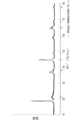
- It is a chart which shows the X-ray-diffraction pattern of positive electrode active material C0 which does not contain Ti.
- 2 is a chart showing an X-ray diffraction pattern of a positive electrode active material C1 obtained in Example 1.
- FIG. 3 is a chart showing an X-ray diffraction pattern of a positive electrode active material C2 obtained in Example 2.
- 6 is a chart showing an X-ray diffraction pattern of positive electrode active material C4 obtained in Example 4.
- FIG. 6 is a chart showing an X-ray diffraction pattern of a positive electrode active material C7 obtained in Example 7.
- 10 is a chart showing an X-ray diffraction pattern of positive electrode active material C9 obtained in Example 9.
- 6 is a chart showing an X-ray diffraction pattern of positive electrode active material C10 obtained in Example 10.
- 10 is a chart showing an X-ray diffraction pattern of positive electrode active material C11 obtained in Example 11.
- 10 is a chart showing an X-ray diffraction pattern of positive electrode active material C13 obtained in Example 13.
- 6 is a chart showing an X-ray diffraction pattern of a positive electrode active material D1 obtained in Comparative Example 1.
- 6 is a chart showing an X-ray diffraction pattern of a positive electrode active material D2 obtained in Comparative Example 2.
- One embodiment of the present invention is a positive electrode active material, which is included in a positive electrode active material layer on the surface of a current collector, and the current collector and the positive electrode active material layer constitute a positive electrode.
- a non-aqueous electrolyte secondary battery having a power generation element having the positive electrode, a negative electrode in which a negative electrode active material layer is formed on the surface of the current collector, and an electrolyte layer is configured.
- at least one of Ti, Zr, and Nb dissolves in the transition metal layer of the positive electrode active material and substitutes the transition metal, thereby suppressing elution of the transition metal.
- the nonaqueous electrolyte secondary battery according to the present embodiment is not particularly limited as long as it is a secondary battery using the positive electrode active material of the present embodiment, and typically a lithium ion secondary battery can be mentioned. That is, the non-aqueous electrolyte secondary battery includes the positive electrode of the present embodiment, a negative electrode containing a negative electrode active material capable of inserting and removing lithium ions, and an electrolyte layer interposed between the positive electrode and the negative electrode. .
- a lithium ion secondary battery will be described as an example, but the present invention is not limited to this.
- FIG. 1 is a schematic cross-sectional view schematically showing the overall structure of a lithium ion secondary battery (hereinafter simply referred to as “parallel stacked battery”) stacked in parallel according to an embodiment of the present invention.
- the parallel laminated battery 10a of the present embodiment has a structure in which a substantially rectangular power generation element 17 in which a charge / discharge reaction actually proceeds is sealed inside a laminate film 22 that is a battery exterior material.
- the power generation element 17 is housed and sealed by using a polymer-metal composite laminate film as a battery exterior material and joining all of its peripheral parts by thermal fusion.
- the power generation element 17 includes a negative electrode in which the negative electrode active material layer 12 is disposed on both sides of the negative electrode current collector 11 (only one side for the lowermost layer and the uppermost layer of the power generation element), an electrolyte layer 13, and a positive electrode current collector 14. And a positive electrode in which the positive electrode active material layer 15 is disposed on both sides.
- the negative electrode, the electrolyte layer 13 and the positive electrode are laminated in this order so that one negative electrode active material layer 12 and the positive electrode active material layer 15 adjacent to the negative electrode active material layer 15 face each other with the electrolyte layer 13 therebetween. Yes.
- a positive electrode active material having a specific composition and structure is used for the positive electrode active material layer.
- the adjacent negative electrode, electrolyte layer 13, and positive electrode constitute one single cell layer 16. Therefore, it can be said that the parallel stacked battery 10 of the present embodiment has a configuration in which a plurality of single battery layers 16 are stacked and electrically connected in parallel. Further, a seal portion (insulating layer) (not shown) for insulating between the adjacent negative electrode current collector 11 and the positive electrode current collector 14 may be provided on the outer periphery of the unit cell layer 16. .
- the negative electrode active material layer 12 is disposed only on one side of the outermost layer negative electrode current collector 11 a located in both outermost layers of the power generation element 17.
- the arrangement of the negative electrode and the positive electrode is reversed so that the outermost positive electrode current collector is positioned on both outermost layers of the power generation element 17, and the positive electrode is provided only on one side of the outermost positive electrode current collector.
- An active material layer may be arranged.
- the negative electrode current collector 11 and the positive electrode current collector 14 are attached with a negative electrode current collector plate 18 and a positive electrode current collector plate 19 that are electrically connected to the respective electrodes (negative electrode and positive electrode), and are sandwiched between ends of the laminate film 22. Thus, it has a structure led out of the laminate film 22.
- the negative electrode current collector 18 and the positive electrode current collector 19 are connected to the negative electrode current collector 11 and the positive electrode current collector 14 of each electrode by ultrasonic welding or resistance via a negative electrode terminal lead 20 and a positive electrode terminal lead 21 as necessary. It may be attached by welding or the like (this form is shown in FIG. 1).
- the negative electrode current collector 11 may be extended to form the negative electrode current collector plate 18 and may be led out from the laminate film 22.
- the positive electrode current collector 14 may be extended to form a positive electrode current collector plate 19, which may be similarly derived from the battery exterior material 22.
- FIG. 2 is a schematic cross-sectional view schematically showing the overall structure of a serially stacked bipolar lithium ion secondary battery (hereinafter also simply referred to as “series stacked battery”) according to an embodiment of the present invention. is there.
- the series stacked battery 10b shown in FIG. 2 has a structure in which a substantially rectangular power generation element 17 in which a charge / discharge reaction actually proceeds is sealed inside a laminate film 22 that is a battery exterior material.
- the power generation element 17 of the series stacked battery 10 b has a positive electrode active material layer 15 electrically coupled to one surface of the current collector 23, and the surface on the opposite side of the current collector 11.
- a plurality of bipolar electrodes 24 each having a negative electrode active material layer 12 electrically coupled thereto.
- a positive electrode active material having a specific composition and structure is used for the positive electrode active material layer.
- Each bipolar electrode 24 is laminated via the electrolyte layer 13 to form the power generation element 17.
- the electrolyte layer 13 has a configuration in which an electrolyte is held at the center in the surface direction of a separator as a base material.
- the positive electrode active material layer 15 of one bipolar electrode 24 and the negative electrode active material layer 12 of another bipolar electrode 24 adjacent to the one bipolar electrode 24 face each other through the electrolyte layer 13.
- Each bipolar electrode 24 and the electrolyte layer 13 are alternately laminated. That is, the electrolyte layer 13 is sandwiched between the positive electrode active material layer 15 of one bipolar electrode 24 and the negative electrode active material layer 12 of another bipolar electrode 24 adjacent to the one bipolar electrode 24. ing.
- the negative electrode active material layer 12 is formed only on one side of the negative electrode side outermost current collector 23b located in the outermost layer of the power generation element 17.
- the positive electrode active material layer 15 may be formed on both surfaces of the outermost layer current collector 23a on the positive electrode side.
- the negative electrode active material layer 12 may be formed on both surfaces of the outermost current collector 23b on the negative electrode side.
- the positive electrode current collector plate 19 is disposed so as to be adjacent to the outermost layer current collector 23a on the positive electrode side, and this is extended and led out from the laminate film 22 which is a battery exterior material. is doing.
- the negative electrode current collector plate 18 is disposed so as to be adjacent to the outermost layer current collector 23b on the negative electrode side, and similarly, this is extended and led out from the laminate film 22 which is an exterior of the battery.
- the insulating portion 25 is usually provided around each unit cell layer 16.
- the insulating portion 25 is intended to prevent the adjacent current collectors 23 in the battery from contacting each other and the occurrence of a short circuit due to a slight irregularity of the end portions of the unit cell layer 16 in the power generation element 17. Provided. By installing such an insulating portion 25, long-term reliability and safety can be ensured, and a high-quality series stacked battery 10b can be provided.
- the number of times the single cell layer 16 is stacked is adjusted according to the desired voltage. Further, in the serially stacked battery 10b, the number of times the single battery layers 16 are stacked may be reduced if a sufficient output can be ensured even if the battery is made as thin as possible. Even in the case of the serially stacked battery 10b, it is necessary to prevent external impact and environmental degradation during use. Therefore, the power generation element 17 is preferably sealed in a laminate film 22 that is a battery exterior material, and the positive electrode current collector plate 19 and the negative electrode current collector plate 18 are taken out of the laminate film 22.
- the nonaqueous electrolyte secondary battery intended for application to an electric vehicle can achieve high output and high capacity, and the capacity is not easily lowered by repeated charge and discharge.
- each configuration of the nonaqueous electrolyte secondary battery will be described in detail.
- the positive electrode has a function of generating electrical energy by transferring lithium ions together with the negative electrode.
- the positive electrode essentially includes a current collector and a positive electrode active material layer, and the positive electrode active material layer is formed on the surface of the current collector.
- the current collector is made of a conductive material, and a positive electrode active material layer is disposed on one side or both sides thereof.
- a conductive resin in which a conductive filler is added to a metal or a conductive polymer material or a non-conductive polymer material may be employed.
- metals examples include aluminum, nickel, iron, stainless steel (SUS), titanium, and copper.
- a clad material of nickel and aluminum, a clad material of copper and aluminum, or a plating material of a combination of these metals can be preferably used.
- covered on the metal surface may be sufficient.
- aluminum, stainless steel, or copper is preferably used from the viewpoint of conductivity and battery operating potential.
- examples of the conductive polymer material include polyaniline, polypyrrole, polythiophene, polyacetylene, polyparaphenylene, polyphenylene vinylene, polyacrylonitrile, and polyoxadiazole. Since such a conductive polymer material has sufficient conductivity without adding a conductive filler, it is advantageous in terms of facilitating the manufacturing process or reducing the weight of the current collector.
- non-conductive polymer materials include polyethylene (PE; high density polyethylene (HDPE), low density polyethylene (LDPE)), polypropylene (PP), polyethylene terephthalate (PET), polyether nitrile (PEN), polyimide ( PI), polyamideimide (PAI), polyamide (PA), polytetrafluoroethylene (PTFE), styrene-butadiene rubber (SBR), polyacrylonitrile (PAN), polymethyl acrylate (PMA), polymethyl methacrylate (PMMA), Examples include polyvinyl chloride (PVC), polyvinylidene fluoride (PVdF), and polystyrene (PS). Such a non-conductive polymer material may have excellent potential resistance or solvent resistance.
- PE polyethylene
- HDPE high density polyethylene
- LDPE low density polyethylene
- PP polypropylene
- PET polyethylene terephthalate
- PEN polyether nitrile
- PI polyimide
- PAI polyamideimide
- the conductive carbon is not particularly limited, but is at least one selected from the group consisting of acetylene black, vulcan, black pearl, carbon nanofiber, ketjen black, carbon nanotube, carbon nanohorn, carbon nanoballoon, and fullerene. Preferably it contains seeds.
- the amount of the conductive filler added is not particularly limited as long as it is an amount capable of imparting sufficient conductivity to the current collector, and is generally about 5 to 35% by mass.
- the size of the current collector is determined according to the intended use of the battery. For example, if it is used for a large battery that requires a high energy density, a current collector having a large area is used.
- the thickness of the current collector is not particularly limited, but is usually about 1 to 100 ⁇ m.
- the positive electrode active material layer essentially includes a positive electrode active material having a specific composition and a specific structure.
- the positive electrode active material layer may further include other positive electrode active materials, conductive assistants, binders and other additives.
- Positive electrode active material has a composition capable of releasing lithium ions during charging and occluding lithium ions during discharging.
- a positive electrode active material having the following composition formula (1) is used.
- X is at least one of Ti, Zr and Nb
- a + b + c + d + e 1.5
- z is represented by the number of oxygens satisfying the valence.
- the positive electrode active material having the composition formula (1) described above has 20-23 °, 35-40 ° (101), 42-45 ° (104), and 64-65 (104-65) in X-ray diffraction (XRD) measurement. 108) / 65-66 (110) has a diffraction peak indicating a rock salt type layered structure. At this time, those having substantially no peak attributed to other than the diffraction peak of the rock salt type layered structure are preferable. More preferably, one having three diffraction peaks at 35-40 ° (101) and one diffraction peak at 42-45 ° (104) is suitable.
- the X-ray diffraction measurement shall employ the measurement method described in the examples described later.
- the notation of 64-65 (108) / 65-66 (110) has two peaks close to 64-65 and 65-66.
- one peak is broadly separated without being clearly separated. It is meant to include.
- the positive electrode active material of composition formula (1) has a plurality of specific diffraction peaks in X-ray diffraction (XRD) measurement.
- the positive electrode active material having the above composition formula is a solid solution system of Li 2 MnO 3 and LiMnO 2.
- the diffraction peak at 20-23 ° is characteristic of Li 2 MnO 3. It is a superlattice diffraction peak.
- the diffraction peaks at 36.5-37.5 ° (101), 44-45 ° (104) and 64-65 (108) / 65-66 (110) are the rock salt type layered structure of LiMnO 2. Is characteristic.
- the positive electrode active material of the present embodiment does not include those having a peak other than a diffraction peak showing a rock salt type layered structure, for example, other peaks derived from impurities, in these angular ranges.
- the positive electrode active material of the present embodiment does not include those having a peak other than a diffraction peak showing a rock salt type layered structure, for example, other peaks derived from impurities, in these angular ranges.
- At least one of Ti, Zr, and Nb is dissolved in the transition metal layer of Ni, Co, and Mn by substituting Mn 4+ to form a rock salt type layered structure It is thought that it forms. Since at least one kind of Ti, Zr and Nb is dissolved, the crystal structure is stabilized, so that it is considered that elution of transition metals including Mn is suppressed during charging and discharging. As a result, even if charging / discharging is repeated, the capacity reduction of the battery can be prevented, and excellent cycle characteristics can be realized. In addition, battery performance itself and durability can be improved.
- the diffraction peak showing the rock salt type layered structure in this embodiment is shifted to the low angle side. That is, the positive electrode active material of the present embodiment has 20-23 °, 35.5-36.5 ° (101), 43.5-44.5 ° (104) and 64 in X-ray diffraction (XRD) measurement. It is preferable to have a diffraction peak at ⁇ 65 (108) / 65-66 (110).
- the shift of the diffraction peak to the lower angle side indicates that Ti and the like are more solid-dissolved in the positive electrode active material and substitutes Mn, which is considered to have a greater effect of suppressing Mn elution.
- Ti or the like substitutes Mn4 + in the transition metal layer of the positive electrode active material, so that the covalent bond between the substituting element and oxygen is strengthened, and the oxygen is released from the crystal lattice accompanying the transition metal oxidation. Can also be reduced. Thereby, generation of oxygen gas can be suppressed, and oxygen defects in the crystal structure can be reduced.
- a + b + c + e satisfies 1.1 ⁇ [a + b + c + e] ⁇ 1.4.
- nickel (Ni), cobalt (Co), and manganese (Mn) are known to contribute to capacity and output characteristics from the viewpoint of improving the purity of the material and improving the electronic conductivity.
- Ti or the like partially substitutes Mn in the crystal lattice.
- 1.1 ⁇ [a + b + c + e] ⁇ 1.2 each element can be optimized and the capacity and output characteristics can be further improved. Therefore, when a positive electrode active material that satisfies this relationship is used in a lithium ion secondary battery, it is possible to exhibit excellent initial charge / discharge efficiency while maintaining high capacity by maintaining high reversible capacity. Become.
- a is preferably 0 ⁇ a ⁇ 1.5, and more preferably 0.1 ⁇ a ⁇ 0.75.
- a is in the above range, a secondary battery having a better capacity retention rate can be obtained.
- a is not a ⁇ 0.75, the crystal structure is not stabilized because nickel is contained in the positive electrode active material within the above range d on condition that nickel (Ni) is divalent. There is.
- a ⁇ 0.75 the crystal structure of the positive electrode active material tends to be a rock salt type layered structure.
- b is preferably 0 ⁇ b ⁇ 1.5, and more preferably 0.2 ⁇ b ⁇ 0.9.
- b is in the above range, a secondary battery having a better capacity retention rate can be obtained.
- manganese is contained in the positive electrode active material within the above range d, provided that manganese is tetravalent, and nickel (Ni) is further contained in the positive electrode active material. Due to the inclusion, the crystal structure may not be stabilized.
- b ⁇ 0.9 the crystal structure of the positive electrode active material tends to be a rock salt type layered structure.
- c is preferably 0 ⁇ c ⁇ 1.5.
- nickel and manganese are contained in the positive electrode active material within the above range d on condition that cobalt is trivalent.
- cobalt (Co) is contained in the positive electrode active material within the above range d on condition that nickel (Ni) is divalent and manganese (Mn) is tetravalent. Therefore, the crystal structure of the positive electrode active material may not be stabilized.
- c ⁇ 0.6 the crystal structure of the positive electrode active material tends to be a rock salt type layered structure.
- composition formula (1) 0.1 ⁇ d ⁇ 0.4.
- d is not 0.1 ⁇ d ⁇ 0.4, the crystal structure of the positive electrode active material may not be stabilized.
- the positive electrode active material tends to have a rock salt type layered structure.
- the range of d is more preferably 0.15 ⁇ d ⁇ 0.35.
- d is 0.1 or more, the composition is less likely to be close to Li 2 MnO 3 and charge / discharge is facilitated, which is preferable.
- composition formula (1) 0.01 ⁇ e ⁇ 0.7.
- e 0.01 ⁇ e ⁇ 0.7, the element cannot be uniformly dissolved in the crystal structure, and the crystal structure cannot be stabilized.
- e 0.01 ⁇ e ⁇ 0.7, at least one of Ti, Zr, and Nb can sufficiently substitute Mn4 + so that elution is suppressed. More preferably, e is 0.02 ⁇ e ⁇ 0.5, and more preferably 0.05 ⁇ e ⁇ 0.3.
- the ionic radius of each element is Mn 4+ 0.540.5, Mn 4+ 0.54 ⁇ , Ti 4+ 0.61 ⁇ , Zr 4+ 0.72 ⁇ , Nb 5+ 0.64 ⁇ , and Ti, Zr and Nb are larger than Mn. ing. Therefore, as Mn 4+ in the positive electrode active material is replaced with Ti or the like, the crystal lattice expands, and the diffraction peak indicating the rock salt type layered structure shifts to a lower angle side. On the contrary, if the diffraction peak is shifted to a lower angle side, the substitution amount of Mn 4+ such as Ti is larger, and the crystal structure is easily stabilized. That is, the elution of Mn at the time of charge / discharge is further suppressed, and the capacity reduction of the secondary battery can be more effectively prevented.
- the specific surface area of the positive electrode active material is preferably 0.2 to 0.6 m 2 / g, and more preferably 0.25 to 0.5 m 2 / g.
- a specific surface area of 0.2 m 2 / g or more is preferable because sufficient battery output can be obtained.
- the specific surface area is 0.6 m 2 / g or less because elution of manganese can be further suppressed.
- the value measured by the method of an Example shall be employ
- the average particle diameter of the positive electrode active material is preferably 10 to 20 ⁇ m, and more preferably 12 to 18 ⁇ m. It is preferable that the average particle size is 10 ⁇ m or more because elution of manganese can be suppressed. On the other hand, when the average particle size is 20 ⁇ m or less, it is preferable that foil breakage, clogging, and the like can be suppressed in the application step to the current collector during the production of the positive electrode.
- the average particle diameter is measured by a laser diffraction / scattering particle size distribution measuring device. The average particle diameter can be measured using, for example, a particle size distribution analyzer (model LA-920) manufactured by Horiba.
- the positive electrode active material can be prepared by the following method. That is, a first step of mixing at least one citrate of Ti, Zr and Nb with an organic acid salt of a transition metal having a melting point of 100 ° C. to 350 ° C., and a mixture obtained in the first step at 100 ° C. A second step of melting at ⁇ 350 ° C., a third step of pyrolyzing the melt obtained in the second step at a temperature higher than the melting point, and a second step of firing the pyrolyzate obtained in the third step. 4 steps. Hereinafter, each step will be described.
- At least one citrate of Ti, Zr and Nb and an organic acid salt of a transition metal having a melting point of 100 ° C. to 350 ° C. are mixed.
- At least one citrate of Ti, Zr and Nb is preferably mixed in the form of an aqueous citric acid complex solution.
- the aqueous solution of at least one kind of citrate complex of Ti, Zr and Nb is not limited to the following, but it can be preferably prepared as follows.
- anhydrous citric acid is dissolved in an organic solvent such as acetone, and at least one alkoxide of Ti, Zr and Nb is added to the solution.
- the molar ratio of at least one of Ti, Zr and Nb to citric acid is preferably (at least one of Ti, Zr and Nb) / citric acid being 1/1 to 1/2.
- the amount of water is appropriately added so that the concentration of the aqueous citric acid complex is 1 to 10% by mass in terms of at least one of Ti, Zr and Nb.
- This aqueous solution is allowed to stand for one day, and the precipitate is filtered to obtain an aqueous solution of at least one citrate complex of Ti, Zr and Nb as a filtrate.
- an alkali metal organic acid salt is further mixed with the above-described aqueous solution of at least one kind of citric acid complex of Ti, Zr and Nb.
- Preferred examples of the organic acid salt of alkali metal include lithium acetate and lithium citrate. It is preferable to mix an alkali metal organic acid salt at this stage because the production method is simple.
- Second Step The mixture obtained in the first step is melted at 100 to 350 ° C., preferably 200 to 300 ° C.
- the pyrolyzate obtained in the third step is calcined at 600 to 1200 ° C., more preferably 800 to 1100 ° C., for 5 to 20 hours, preferably 10 to 15 hours.
- Temporary baking may be performed before baking, in which case the temporary baking may be performed at 200 to 700 ° C., more preferably 300 to 600 ° C. for 1 to 10 hours, more preferably 2 to 6 hours.
- the positive electrode active material of this embodiment is obtained.
- Conductive aid A conductive aid refers to an additive blended to improve the conductivity of the active material layer.
- the positive electrode active material layer contains a conductive material, an electronic network inside the positive electrode active material layer is effectively formed, and the output characteristics of the battery can be improved.
- Various carbons such as carbon powders, such as acetylene black, carbon black, channel black, thermal black, Ketjen black, and graphite, and vapor growth carbon fiber (VGCF; registered trademark). Examples thereof include fibers and expanded graphite.
- the content of the conductive auxiliary with respect to the total amount of the positive electrode active material layer is usually 0 to 30% by mass, preferably 1 to 10% by mass, and more preferably 3 to 7% by mass.
- the binder is added for the purpose of maintaining the electrode structure by binding the constituent members in the active material layer or the active material layer and the current collector.
- the binder is not particularly limited, but polyvinylidene fluoride (PVdF), carboxymethyl cellulose (CMC), polytetrafluoroethylene (PTFE), polyvinyl acetate, acrylic resin, polyimide, epoxy resin, polyurethane resin, urea resin, styrene- Examples thereof include a synthetic rubber binder such as butadiene rubber (SBR).
- PVdF polyvinylidene fluoride
- CMC carboxymethyl cellulose
- PTFE polytetrafluoroethylene
- SBR butadiene rubber
- the negative electrode has a function of generating electrical energy by transferring lithium ions together with the positive electrode.
- the negative electrode essentially includes a current collector and a negative electrode active material layer, and the negative electrode active material layer is formed on the surface of the current collector.
- the negative electrode active material layer includes a negative electrode active material.
- the negative electrode active material layer may further include additives such as a conductive additive and a binder.
- the negative electrode active material may be used alone or in the form of a mixture of two or more.
- the element alloying with lithium is not limited to the following, but specifically, Si, Ge, Sn, Pb, Al, In, Zn, H, Ca, Sr, Ba, Ru, Rh, Ir, Pd, Pt, Ag, Au, Cd, Hg, Ga, Tl, C, N, Sb, Bi, O, S, Se, Te, Cl, and the like.
- the negative electrode active materials it is preferable to include a carbon material and / or at least one element selected from the group consisting of Si, Ge, Sn, Pb, Al, In, and Zn. Or Sn is more preferable, and it is particularly preferable to use a carbon material.
- the carbonaceous particles are preferably those whose surfaces are coated with amorphous carbon. At that time, it is more preferable that the amorphous carbon covers the entire surface of the carbonaceous particles, but it may be a coating of only a part of the surface. By covering the surfaces of the carbonaceous particles with amorphous carbon, it is possible to prevent the graphite and the electrolytic solution from reacting during charging and discharging of the battery.
- the method for coating the surface of the graphite particles with amorphous carbon is not particularly limited.
- the BET specific surface area of the negative electrode active material is preferably 0.8 to 1.5 m 2 / g. If the specific surface area is in the above range, the cycle characteristics of the nonaqueous electrolyte secondary battery can be improved.
- the tap density of the negative electrode active material is preferably 0.9 to 1.2 g / cm 3 . It is preferable from the viewpoint of energy density that the tap density is in the above range.
- Conductive auxiliary agent The conductive auxiliary agent that can be used for the negative electrode is the same as the conductive auxiliary agent that can be used for the positive electrode.
- binder that can be used for the negative electrode is the same as the binder that can be used for the positive electrode, description thereof is omitted here.
- the liquid electrolyte has a form in which a lithium salt is dissolved in an organic solvent.
- organic solvent include dimethyl carbonate (DMC), diethyl carbonate (DEC), dipropyl carbonate (DPC), methyl propyl carbonate (MPC), ethyl propyl carbonate (EPC), methyl ethyl carbonate (MEC), ethylene carbonate ( EC), propylene carbonate (PC), butylene carbonate (BC), fluorine-containing cyclic carbonate (fluoroethylene carbonate (FEC), etc.), fluorine-containing chain carbonate, fluorine-containing chain ether, and fluorine-containing chain ester. Can be mentioned.
- LiPF6 LiN (SO 2 C 2 F 5 ) 2 , LiN (SO 2 CF 3 ) 2 , LiBF 4 , LiClO 4 , LiAsF 6 , LiSO 3 CF 3, or the like can be used.
- the lithium salt concentration is preferably from 0.1 to 5 mol / L, more preferably from 0.1 to 2 mol / L.
- organic sulfone compounds organic disulfone compounds, vinylene carbonate derivatives, ethylene carbonate derivatives, ester derivatives, divalent phenol derivatives, terphenyl derivatives, phosphate derivatives, and lithium fluorophosphate derivatives It is preferable that at least one of these is included. Of these, lithium fluorophosphate derivatives such as lithium monofluorophosphate and lithium difluorophosphate are more preferable. Use of these additives is preferable from the viewpoints of performance and life characteristics.
- the additive is preferably contained in the electrolytic solution at 0.1 to 5% by mass, more preferably 0.5 to 3.5% by mass.
- polymer electrolytes are classified into gel electrolytes containing an electrolytic solution and polymer solid electrolytes not containing an electrolytic solution.
- the gel electrolyte has a configuration in which the above liquid electrolyte is injected into a matrix polymer having lithium ion conductivity.
- the matrix polymer having lithium ion conductivity include polyethylene oxide (PEO), polypropylene oxide (PPO), and copolymers thereof.
- PEO polyethylene oxide
- PPO polypropylene oxide
- copolymers thereof in such a matrix polymer, an electrolyte salt such as a lithium salt can be well dissolved.
- a separator may be used for the electrolyte layer.
- the separator include a microporous film made of polyolefin such as polyethylene or polypropylene, hydrocarbon such as polyvinylidene fluoride-hexafluoropropylene (PVdF-HFP), glass fiber, or the like.
- the polymer solid electrolyte has a structure in which a lithium salt is dissolved in the above matrix polymer and does not contain an organic solvent. Therefore, when the electrolyte layer is composed of a polymer solid electrolyte, there is no fear of liquid leakage from the battery, and the battery reliability can be improved.
- a matrix polymer of a polymer gel electrolyte or a polymer solid electrolyte can exhibit excellent mechanical strength by forming a crosslinked structure.
- thermal polymerization, ultraviolet polymerization, radiation polymerization, electron beam polymerization, etc. are performed on a polymerizable polymer (for example, PEO or PPO) for forming a polymer electrolyte, using an appropriate polymerization initiator.
- a polymerization treatment may be performed.
- the said electrolyte may be contained in the active material layer of an electrode.
- the material constituting the current collector plate is not particularly limited, and a known highly conductive material conventionally used as a current collector plate for a lithium ion secondary battery can be used.
- a constituent material of the current collector plate for example, metal materials such as aluminum, copper, titanium, nickel, stainless steel (SUS), and alloys thereof are preferable. From the viewpoint of light weight, corrosion resistance, and high conductivity, aluminum and copper are more preferable, and aluminum is particularly preferable. Note that the same material may be used for the positive electrode current collector plate (positive electrode tab) and the negative electrode current collector plate (negative electrode tab), or different materials may be used.
- the seal portion is a member unique to the serially stacked battery and has a function of preventing leakage of the electrolyte layer. In addition to this, it is possible to prevent current collectors adjacent in the battery from coming into contact with each other and a short circuit due to a slight unevenness at the end of the laminated electrode.
- the constituent material of the seal part is not particularly limited, but polyolefin resin such as polyethylene and polypropylene, epoxy resin, rubber, polyimide and the like can be used. Among these, it is preferable to use a polyolefin resin from the viewpoints of corrosion resistance, chemical resistance, film-forming property, economy, and the like.
- a lead used in a known laminated secondary battery can be used.
- the parts removed from the battery exterior material should be heat-insulating so that they do not affect products (for example, automobile parts, especially electronic devices) by touching peripheral devices or wiring and causing leakage. It is preferable to coat with a heat shrinkable tube or the like.
- the laminate film can be configured as a three-layer structure in which, for example, polypropylene, aluminum, and nylon are laminated in this order. By using such a laminate film, it is possible to easily open the exterior material, add the capacity recovery material, and reseal the exterior material.
- the manufacturing method of the nonaqueous electrolyte secondary battery is not particularly limited, and can be manufactured by a known method. Specifically, it includes (1) production of electrodes, (2) production of single cell layers, (3) production of power generation elements, and (4) production of stacked batteries.
- the manufacturing method of a nonaqueous electrolyte secondary battery it is not limited to this.
- the electrode (positive electrode and negative electrode) is prepared, for example, by preparing an active material slurry (positive electrode active material slurry or negative electrode active material slurry) and applying the active material slurry onto a current collector. It can be made by drying, then pressing.
- the active material slurry includes the above-described active material (positive electrode active material or negative electrode active material) and a solvent.
- the conductive support agent and the binder may further be included. Since the positive electrode active material slurry essentially includes the positive electrode active material having the above specific composition and structure, this embodiment also provides a positive electrode.
- the solvent is not particularly limited, and N-methyl-2-pyrrolidone (NMP), dimethylformamide, dimethylacetamide, methylformamide, cyclohexane, hexane, water and the like can be used.
- NMP N-methyl-2-pyrrolidone
- the method for applying the active material slurry to the current collector is not particularly limited, and examples thereof include a screen printing method, a spray coating method, an electrostatic spray coating method, an ink jet method, and a doctor blade method.
- the method for drying the coating film formed on the surface of the current collector is not particularly limited as long as at least a part of the solvent in the coating film is removed.
- An example of the drying method is heating. Drying conditions (drying time, drying temperature, etc.) can be appropriately set according to the volatilization rate of the solvent contained in the applied active material slurry, the coating amount of the active material slurry, and the like. A part of the solvent may remain. The remaining solvent can be removed by a press process described later.
- the pressing means is not particularly limited, and for example, a calendar roll, a flat plate press, or the like can be used.
- the single cell layer can be produced by laminating the electrodes (positive electrode and negative electrode) produced in (1) via an electrolyte layer.
- the power generation element can be produced by laminating the single cell layers in consideration of the output and capacity of the single cell layer, the output and capacity required for the battery, and the like.
- the structure of the battery various shapes such as a rectangular shape, a paper shape, a laminated shape, a cylindrical shape, and a coin shape can be adopted.
- the current collector and insulating plate of the component parts are not particularly limited, and may be selected according to the above shape.
- a stacked battery is preferable.
- a lead is joined to the current collector of the power generation element obtained above, and the positive electrode lead or the negative electrode lead is joined to the positive electrode tab or the negative electrode tab.
- a power generation element is placed in a laminate sheet so that the positive electrode tab and the negative electrode tab are exposed to the outside of the battery, and an electrolytic solution is injected with a liquid injector and then sealed in a vacuum to produce a stacked battery. sell.
- Example 1 (Preparation of aqueous solution of titanium citrate complex) 60 g (0.3 mol) of anhydrous citric acid (molecular weight 192.12 g / mol) was added to 400 ml of acetone and heated to 60 ° C. to dissolve. Next, 56 g (0.2 mol) of titanium tetraisopropoxide (molecular weight 284.22 g / mol) was added to form a precipitate. This liquid was subjected to suction filtration to obtain a precipitate (light yellow).
- Ti concentration was 5.0% by weight as TiO 2 (molecular weight 79.87 g / mol).
- the obtained melted solution (slurry) was sprayed by heating at 200 ° C. to 400 ° C. and dried.
- the obtained dry powder was calcined at 600 ° C. for 4 hours and then calcined at 900 ° C. for 12 hours.
- Cu-K ⁇ rays were used as the X-ray source, and the measurement conditions were a tube voltage of 40 KV, a tube current of 20 mA, a scanning speed of 2 ° / min, a divergence slit width of 0.5 °, and a light receiving slit width of 0.15 °.
- FIG. 3 shows a positive electrode active material C0 having the following composition that does not contain Ti for comparison.
- the X-ray diffraction pattern of is shown.
- FIG. 4 shows an X-ray diffraction pattern of the positive electrode active material C1.
- FIGS. 3 and 4 a peak attributed to the superlattice structure characteristic of the solid solution system is observed at 20-23 °. Furthermore, in FIG. 4, the peaks at 36.5-37.5 (101) and 44-45 ° (104) and 64-65 ° (108) / 65-66 (110) are slightly shifted to the lower angle side. It was observed. Further, no diffraction peak attributed to the spinel phase was observed in any sample.
- Positive electrode active material C1 Composition formula Li 1.5 [Ni 0.375 Mn 0.775 [Li] 0.25 Ti 0.10 ] O z 100 parts by weight
- Conductive agent flake graphite 1.0 part by weight acetylene black 3.0 parts by weight
- Binder 3.0 parts by weight of polyvinylidene fluoride (PVDF)
- Solvent 65 parts by weight of N-methylpyrrolidone (NMP)
- a positive electrode slurry having the above composition was prepared as follows. First, a binder solution was prepared by dissolving 3.0 parts by weight of a binder in 30 parts by weight of NMP. Next, the mixed powder of 4.0 parts by weight of the conductive agent and 100 parts by weight of the positive electrode active material powder is kneaded with a planetary mixer (PVM100, manufactured by Asada Tekko) in addition to 33.0 parts by weight of the binder solution. Then, 35 parts by weight of NMP was added to the kneaded product to obtain a positive electrode slurry (solid content concentration: 62% by weight).
- Electrode press The sheet-like electrode was compression-molded by applying a roller press and cut to prepare a positive electrode C1 having a weight of about 11.0 mg / cm 2 , a thickness of about 50 ⁇ m, and a density of 2.70 g / cm 3 of the active material layer on one side. .
- the positive electrode C1 was subjected to a drying process in a vacuum drying furnace. After installing the positive electrode C1 inside the drying furnace, the pressure in the drying furnace was reduced at room temperature (25 ° C.) (100 mmHg (1.33 ⁇ 104 Pa)) to remove air in the drying furnace. Subsequently, while circulating nitrogen gas (100 cm 3 / min), the temperature was raised to 120 ° C. at 10 ° C./min, the pressure was reduced again at 120 ° C., and nitrogen was maintained in the furnace for 12 hours, The temperature was lowered. In this way, a positive electrode C11 was obtained.
- room temperature 25 ° C.
- nitrogen gas 100 cm 3 / min
- Active material 100 parts by weight of natural graphite
- Conductive agent 1.0 part by weight of acetylene black
- Binder 5.0 parts by weight of polyvinylidene fluoride (PVDF)
- Solvent 97 parts by weight of N-methylpyrrolidone (NMP) (Production of negative electrode slurry)
- a negative electrode slurry having the above composition was prepared as follows. First, a binder solution was prepared by dissolving 5.0 parts by weight of a binder in 50 parts by weight of NMP.
- the mixed powder of 1.0 part by weight of a conductive agent and 100 parts by weight of natural graphite powder is kneaded with a planetary mixer (PVM100, manufactured by Asada Tekko), and then 47 parts by weight of NMP was added to the kneaded product to obtain a negative electrode slurry (solid content concentration 52% by weight).
- a planetary mixer manufactured by Asada Tekko
- the specific surface area was 1.05 m 2 / g (measuring device: BELSORP-miniII manufactured by Nippon Bell), and the tap density was 1.1 g / cm 3 (measuring device: tap density measuring device manufactured by Nihon Lucas).
- Negative electrode coating amount (mg / cm 2), the one surface of the coating weight was about 9.50mg / cm 2.
- the negative electrode slurry was applied to one surface of the current collector foil by a die coater while the 10 ⁇ m thick electrolytic copper foil current collector foil was run at a running speed of 1.5 m / min. Subsequently, the current collector foil coated with this negative electrode slurry was dried in a hot air drying oven at 100 ° C. to 110 ° C. for a drying time of 2 minutes, and the amount of NMP remaining in the electrode active material layer was 0.02 wt%. It was as follows. Further, coating and drying were performed on the back surface of the electrolytic copper foil in the same manner as described above to form a sheet-like electrode having electrode active material layers on both sides.
- Electrode press The obtained sheet-like electrode was compression-molded by a roller press and cut to prepare a negative electrode A1 having a weight of about 9.50 mg / cm 2 and a density of 1.45 g / cm 3 of the active material layer on one side. When the surface of the negative electrode A1 was observed, no cracks were observed.
- a tab was welded to the current collector foil portions of positive electrode C11 (active material layer area length: 3.6 cm ⁇ width: 5.3 cm) and negative electrode A11 (active material layer area length: 3.8 cm ⁇ width: 5.5 cm).
- a porous polypropylene separator (S) (4.5 cm long ⁇ 6.0 cm wide, 25 ⁇ m thick, porosity 55%) is sandwiched between the negative electrode A11 and the positive electrode C11 welded with these tabs.
- a battery element of a stacked type (stacked example, A11- (S) -C11- (S) -A11) was produced. Next, both sides were sandwiched between aluminum laminate films (length 5.0 cm ⁇ width 6.5 cm), and the battery element was housed by thermocompression sealing at three sides.
- ethylene carbonate (EC) 30 vol. % And diethyl carbonate (DEC) 70 vol. % LiPF 6 (electrolyte) is dissolved in 1.0% of a mixed solvent, and then lithium difluorophosphate (LiPO 2 F 2 ) is 1.8% by weight as lithium fluorophosphate acting as an additive. Then, 1.0% by weight of lithium monofluorophosphate (Li 2 PO 3 F) was dissolved to obtain an electrolytic solution. After injecting this electrolytic solution of 0.6 cm 3 / cell, the remaining one side was temporarily sealed by thermocompression bonding to produce a laminate type cell. In order to sufficiently infiltrate the electrolyte into the electrode pores, the electrolyte was held at 25 ° C. for 24 hours while being pressurized at a surface pressure of 0.5 Mpa.
- the battery element was set on an evaluation cell attachment jig, and a positive electrode lead and a negative electrode lead were attached to each tab end of the battery element, and a test was performed.
- Example 21 [Evaluation of battery characteristics] The battery produced in Example 21 was subjected to initial charge treatment and activation treatment under the following conditions, and performance was evaluated.
- the battery aging treatment was performed as follows. At 25 ° C., the battery was charged at a constant current charging method of 0.05 C for 4 hours (SOC approximately 20%). Subsequently, after charging to 4.35 V at a 0.1 C rate at 25 ° C., the charging was stopped, and the state (SOC about 70%) was maintained for about 2 days (48 hours).
- thermocompression bonding One side temporarily sealed by thermocompression bonding was opened, gas was removed at 10 ⁇ 3 hPa for 5 minutes, and then thermocompression bonding was performed again to perform temporary sealing. Furthermore, pressure (surface pressure 0.5 ⁇ 0.1 MPa) was shaped with a roller, and the electrode and the separator were sufficiently adhered.
- thermocompression bonding One side temporarily sealed by thermocompression bonding was opened, gas was removed at 10 ⁇ 3 hPa for 5 minutes, and then thermocompression bonding was performed again to perform main sealing. Furthermore, pressure (surface pressure 0.5 ⁇ 0.1 MPa) was shaped with a roller, and the electrode and the separator were sufficiently adhered.
- the battery is evaluated by the constant current constant voltage charging method in which the battery is charged at a 0.1 C rate until the maximum voltage reaches 4.5 V and then held for about 1 to 1.5 hours.
- the constant current discharge method was used in which discharge was performed at a 0.1 C rate until the minimum voltage reached 2.0V. All were performed at room temperature.
- the ratio of the discharge capacity at the 300th cycle to the discharge capacity at the first cycle was compared as a capacity maintenance rate. Further, the ratio of the DCR at the 300th cycle to the direct current resistance (DCR) at the first cycle was compared as the DCR increase rate.
- DCR direct current resistance
- Example 2 (Preparation of Positive Electrode Active Material C2) Li 1.5 [Ni 0.375 Mn 0.775 [Li] 0.25 Ti 0.10 ] O z
- an aqueous titanium citrate complex solution (5.0% by weight as TiO 2 ) obtained in the same manner as in Example 1, 15.93 g of manganese acetate tetrahydrate (molecular weight: 245.09 g / mol), acetic acid Nickel tetrahydrate (molecular weight 248.84 g / mol) 6.22 g, lithium acetate dihydrate (molecular weight 102.02 g / mol) 15.31 g 1.01 times the amount (15.46 g) It was.
- the obtained mixture was heated to 200 ° C. to 300 ° C. to melt and dissolve.
- the obtained melt solution (slurry) was sprayed by heating at 200 ° C. to 400 ° C. and dried using a spray drying apparatus.
- the obtained dry powder was calcined at 600 ° C. for 4 hours and then calcined at 900 ° C. for 12 hours.
- 10 g of the calcined powder was added to 100 ml of pure water, stirred and mixed for 2 minutes, and then quickly filtered with suction.
- the filtrate was dried at 200 ° C. and then calcined at 400 ° C. for 1 hour.
- FIG. 5 shows an X-ray diffraction pattern of the positive electrode active material C2. In the X-ray diffraction pattern, the same peak as that of the positive electrode active material C1 of Example 1 was observed.
- the evaluation cell was produced according to Example 1, and after performing the initial charge process and the activation process, performance evaluation and lifetime evaluation were performed. The evaluation results are shown in Tables 1 and 3 below.
- Example 3 A positive electrode active material C3 was produced according to Example 2. Moreover, the evaluation cell was produced according to Example 1, and after performing the initial charge process and the activation process, performance evaluation and lifetime evaluation were performed. The evaluation results are shown in Tables 1 and 3 below.
- FIG. 6 shows the X-ray diffraction pattern of the positive electrode active material C4 by a solid line.
- the pattern of the positive electrode active material C1 of Example 1 is shown by a solid line in FIG.
- the positive electrode active material C4 has a peak at 36.5-37.5 (101) to 35.5-36.5 (101), and a peak at 44-45 ° (104) of 43.5-44.5 ° ( A shift toward the lower angle side to 104) was observed. Furthermore, a tendency was observed for the peaks of 64-65 ° (108) / 65-66 (110) to overlap. This is considered because the solid solution amount of titanium increased in the positive electrode active material C4.
- Example 6 to 8 Cathode active materials C6 to C8 were prepared in the same manner as in Example 2 except that the amount of lithium acetate charged was changed to 1.10 times.
- FIG. 7 shows an X-ray diffraction pattern of the positive electrode active material C7. In the X-ray diffraction pattern, the same peak as that of the positive electrode active material C1 of Example 1 was observed.
- the evaluation cell was produced according to Example 1, and after performing the initial charge process and the activation process, performance evaluation and lifetime evaluation were performed. The evaluation results are shown in Tables 1 and 3 below.
- Example 9 A positive electrode active material C9 was produced in the same manner as in Example 2 except that the amount of lithium acetate charged was changed to 1.05 times.
- FIG. 8 shows an X-ray diffraction pattern of the positive electrode active material C9. In the X-ray diffraction pattern, the same peak as that of the positive electrode active material C1 of Example 1 was observed.
- the evaluation cell was produced according to Example 1, and after performing the initial charge process and the activation process, performance evaluation and lifetime evaluation were performed. The evaluation results are shown in Tables 1 and 3 below.
- a positive electrode active material C10 was produced according to Example 9 except that the titanium citrate thus obtained was used.
- FIG. 9 shows an X-ray diffraction pattern of the positive electrode active material C10. In the X-ray diffraction pattern, the same peak as that of the positive electrode active material C1 of Example 1 was observed.
- an evaluation cell was prepared according to Example 1, and after performing the initial charging process and the activation process, performance evaluation and life evaluation were performed.
- the evaluation results are shown in Tables 1 and 3 below.
- Example 11 (Preparation of zirconium citrate complex aqueous solution) 60 g (0.3 mol) of anhydrous citric acid (molecular weight 192.12 g / mol) was added to 400 ml of acetone and heated to 60 ° C. to dissolve. Subsequently, 77.53 g (0.2 mol) of zirconium tetraisopropoxide (molecular weight 387.67 g / mol) was added to form a precipitate. This liquid was subjected to suction filtration to obtain a precipitate (light yellow). H 2 O (200 ml) was added to the precipitate and heated to 50-60 ° C. to dissolve.
- anhydrous citric acid molecular weight 192.12 g / mol
- 77.53 g (0.2 mol) of zirconium tetraisopropoxide molecular weight 387.67 g / mol
- the obtained solution was allowed to stand for 1 day or longer to precipitate insoluble matters, and then filtered to remove insoluble matters, thereby obtaining a zirconium citrate complex aqueous solution.
- the Zr concentration was 5.0% by weight as ZrO 2 .
- a positive electrode active material C11 having the following composition was prepared according to Example 9 except that a zirconium citrate complex aqueous solution was used instead of the titanium citrate complex aqueous solution.
- FIG. 10 shows an X-ray diffraction pattern of the positive electrode active material C11. In the X-ray diffraction pattern, the same peak as that of the positive electrode active material C1 of Example 1 was observed.
- an evaluation cell was prepared according to Example 1, and after performing initial charge treatment and activation treatment, performance evaluation and life evaluation were performed. The evaluation results are shown in Tables 1 and 3 below.
- a positive electrode active material C12 having the following composition was prepared according to Example 9 except that a zirconium citrate complex aqueous solution was used instead of the titanium citrate complex aqueous solution.
- Composition formula: Li 1.5 [Ni 0.375 Mn 0.775 [Li] 0.25 Zr 0.10 ] O z Using the obtained positive electrode active material C12, an evaluation cell was prepared according to Example 1, and after performing the initial charging process and the activation process, performance evaluation and life evaluation were performed. The evaluation results are shown in Tables 1 and 3 below.
- Example 13 (Preparation of niobium citrate complex aqueous solution) 60 g (0.3 mol) of anhydrous citric acid (molecular weight 192.12 g / mol) was added to 400 ml of acetone and heated to 60 ° C. to dissolve. Next, 63.64 g (0.2 mol) of niobium pentaethoxide (molecular weight 318.21 g / mol) was added to form a precipitate. This liquid was subjected to suction filtration to obtain a precipitate (light yellow). H 2 O (200 ml) was added to the resulting precipitate and heated to 50-60 ° C. to dissolve.
- the obtained solution was allowed to stand for 1 day or longer to precipitate the insoluble matter, and then filtered to remove the insoluble matter to obtain a niobium citrate complex aqueous solution.
- the Nb concentration was 5.0% by weight as Nb 2 O 5 .
- a positive electrode active material C13 having the following composition was prepared according to Example 9 except that a niobium citrate complex aqueous solution was used instead of the titanium citrate complex aqueous solution.
- FIG. 11 shows an X-ray diffraction pattern of the positive electrode active material C13. In the X-ray diffraction pattern, the same peak as that of the positive electrode active material C1 of Example 1 was observed.
- an evaluation cell was produced according to Example 1, and after performing an initial charging process and an activation process, performance evaluation and lifetime evaluation were performed. The evaluation results are shown in Tables 1 and 3 below.
- a positive electrode active material C14 having the following composition was prepared according to Example 9 except that a niobium citrate complex aqueous solution was used instead of the titanium citrate complex aqueous solution.
- Composition formula: Li 1.5 [Ni 0.375 Mn 0.775 [Li] 0.25 Nb 0.05 ] O z Using the obtained positive electrode active material C14, an evaluation cell was prepared according to Example 1, and after performing the initial charging process and the activation process, performance evaluation and life evaluation were performed.
- the positive electrode active material D1 thus obtained had the following composition.
- FIG. 13 shows the X-ray diffraction pattern of the positive electrode active material D1 with a solid line.
- the X-ray diffraction pattern of the positive electrode active material C1 of Example 1 is indicated by a broken line.
- an impurity peak indicated by a downward arrow was observed.
- an evaluation cell was prepared according to Example 1, and after performing the initial charging process and the activation process, performance evaluation and life evaluation were performed. The evaluation results are shown in Tables 2 and 4 below.
- the positive electrode active material D2 thus obtained had the following composition.
- FIG. 14 shows the X-ray diffraction pattern of the positive electrode active material D2 with a solid line.
- the X-ray diffraction pattern of the positive electrode active material C1 of Example 1 is indicated by a broken line.
- an impurity peak indicated by a downward arrow was observed.
- an evaluation cell was prepared according to Example 1, and after performing the initial charging process and the activation process, performance evaluation and life evaluation were performed. The evaluation results are shown in Tables 2 and 4 below.
Landscapes
- Chemical & Material Sciences (AREA)
- General Chemical & Material Sciences (AREA)
- Electrochemistry (AREA)
- Chemical Kinetics & Catalysis (AREA)
- Inorganic Chemistry (AREA)
- Engineering & Computer Science (AREA)
- Manufacturing & Machinery (AREA)
- General Physics & Mathematics (AREA)
- Condensed Matter Physics & Semiconductors (AREA)
- Physics & Mathematics (AREA)
- Organic Chemistry (AREA)
- Materials Engineering (AREA)
- Battery Electrode And Active Subsutance (AREA)
- Secondary Cells (AREA)
- Composite Materials (AREA)
Abstract
Description
Li1.5[NiaMnbCoc[Li]d[X]e]Oz (1)
ここで、Xは、Ti、ZrおよびNbからなる少なくとも1種であり、0.01≦e≦0.7、a+b+c+d+e=1.5、0.1≦d≦0.4、1.1≦[a+b+c+e]≦1.4である。zは、原子価を満足する酸素数で表される。さらに、組成式(1)の正極活物質は、X線回折(XRD)測定において、20-23°、35-40°(101)、42-45°(104)および64-65(108)/65-66(110)に、岩塩型層状構造を示す回折ピークを有する。
本実施形態に係る非水電解質二次電池は、本実施形態の正極活物質を使用した二次電池であれば特に制限はなく、典型的にはリチウムイオン二次電池が挙げられる。すなわち、本実施形態の正極と、リチウムイオンを挿入・脱離可能な負極活物質を含有する負極と、前記正極および前記負極の間に介在する電解質層とを備える非水電解質二次電池である。以下の説明では、リチウムイオン二次電池を例に挙げて説明するが、本発明はこれに限定されない。
正極は、負極とともにリチウムイオンの授受により電気エネルギーを生み出す機能を有する。正極は、集電体および正極活物質層を必須に含み、集電体の表面に正極活物質層が形成されてなる。
集電体は導電性材料から構成され、その一方の面または両面に正極活物質層が配置される。集電体を構成する材料に特に制限はなく、例えば、金属や、導電性高分子材料または非導電性高分子材料に導電性フィラーが添加された導電性を有する樹脂が採用されうる。
正極活物質層は特定の組成および特定の構造の正極活物質を必須に含む。前記正極活物質層は、それ以外の正極活物質、導電助剤、バインダ等の添加剤をさらに含んでもよい。
正極活物質は、充電時にリチウムイオンを放出し、放電時にリチウムイオンを吸蔵できる組成を有する。本実施形態では、以下の組成式(1)を有する正極活物質を使用する。
ここで、XはTi、ZrおよびNbからなる少なくとも1種であり、a+b+c+d+e=1.5、1.1≦[a+b+c+e]≦1.4、0.1≦d≦0.4、0.01≦e≦0.7である。zは原子価を満足する酸素数で表される。
第1工程では、Ti、ZrおよびNbの少なくとも一種のクエン酸塩および融点が100℃~350℃の遷移金属の有機酸塩とを混合する。Ti、ZrおよびNbの少なくとも一種のクエン酸塩は、好ましくは、クエン酸錯体水溶液の形態で混合する。Ti、ZrおよびNbの少なくとも一種のクエン酸錯体水溶液は、以下に限定はされないが、好ましくは以下のように調製できる。
第1工程で得られた混合物を、100℃~350℃、好ましくは200~300℃で融解する。
第2工程で得られた加熱溶融物(スラリー)を、第1工程で使用した遷移金属の有機酸塩の融点以上の温度で熱分解し、乾燥粉末である熱分解物を得る。複数の遷移金属の有機酸塩の融点がそれぞれ異なる場合には、最も高い融点以上の温度で熱分解する。より詳細には、溶融物をスプレー装置で、200~600℃、より好ましくは200~400℃で加熱噴霧することができる。
第3工程で得られた熱分解物を、600~1200℃、より好ましくは800~1100℃で、5~20時間、好ましくは10~15時間焼成する。焼成の前に仮焼成を行ってもよく、その場合は、200~700℃、より好ましくは300~600℃で、1~10時間、より好ましくは2~6時間仮焼成することができる。このようにして、本実施形態の正極活物質が得られる。
導電助剤とは、活物質層の導電性を向上させるために配合される添加物をいう。正極活物質層が導電性材料を含むことにより、正極活物質層の内部における電子ネットワークが効果的に形成され、電池の出力特性が向上しうる。
バインダは、活物質層中の構成部材同士または活物質層と集電体とを結着させて電極構造を維持する目的で添加される。
負極は、正極とともにリチウムイオンの授受により電気エネルギーを生み出す機能を有する。負極は、集電体および負極活物質層を必須に含み、集電体の表面に負極活物質層が形成されてなる。
負極に用いられうる集電体は、正極に用いられうる集電体と同様であるため、ここでは説明を省略する。
負極活物質層は負極活物質を含む。前記負極活物質層は、導電助剤、バインダ等の添加剤をさらに含んでもよい。
負極活物質は、放電時にリチウムイオンを放出し、充電時にリチウムイオンを吸蔵できる組成を有する。負極活物質は、リチウムを可逆的に吸蔵および放出できるものであれば特に制限されないが、負極活物質の例としては、SiやSnなどの金属、あるいはTiO、Ti2O3、TiO2、もしくはSiO2、SiO、SnO2などの金属酸化物、Li4/3Ti5/3O4もしくはLi7MnNなどのリチウムと遷移金属との複合酸化物、Li-Pb系合金、Li-Al系合金、Li、または炭素粉末、天然黒鉛、人造黒鉛、カーボンブラック、活性炭、カーボンファイバー、コークス、ソフトカーボン、もしくはハードカーボンなどの炭素材料などが好ましく挙げられる。このうち、リチウムと合金化する元素を用いることにより、従来の炭素系材料に比べて高いエネルギー密度を有する高容量および優れた出力特性の電池を得ることが可能となる。上記負極活物質は、単独で使用されてもあるいは2種以上の混合物の形態で使用されてもよい。上記のリチウムと合金化する元素としては、以下に制限されることはないが、具体的には、Si、Ge、Sn、Pb、Al、In、Zn、H、Ca、Sr、Ba、Ru、Rh、Ir、Pd、Pt、Ag、Au、Cd、Hg、Ga、Tl、C、N、Sb、Bi、O、S、Se、Te、Cl等が挙げられる。
負極に用いられうる導電助剤は、正極に用いられうる導電助剤と同様であるため、ここでは説明を省略する。
負極に用いられうるバインダは、正極に用いられうるバインダと同様であるため、ここでは説明を省略する。
電解質層は、正極と負極との間の空間的な隔壁(スペーサ)として機能する。また、これと併せて、充放電時における正負極間でのリチウムイオンの移動媒体である電解質を保持する機能をも有する。電解質層を構成する電解質に特に制限はなく、液体電解質、ならびに高分子ゲル電解質および高分子固体電解質などのポリマー電解質が適宜用いられうる。本実施形態では、液体電解質が好ましい。
リチウムイオン二次電池においては、電池外部に電流を取り出す目的で、集電体に電気的に接続された集電板(タブ)が外装材であるラミネートフィルムの外部に取り出されている。
シール部は、直列積層型電池に特有の部材であり、電解質層の漏れを防止する機能を有する。このほかにも、電池内で隣り合う集電体同士が接触したり、積層電極の端部の僅かな不ぞろいなどによる短絡が起こったりするのを防止することもできる。
負極および正極端子リードの材料は、公知の積層型二次電池で用いられるリードを用いることができる。なお、電池外装材から取り出された部分は、周辺機器や配線などに接触して漏電したりして製品(例えば、自動車部品、特に電子機器等)に影響を与えないように、耐熱絶縁性の熱収縮チューブなどにより被覆するのが好ましい。
外装材としては、従来公知の金属缶ケースを用いることができる。そのほか、図1に示すようなラミネートフィルム22を外装材として用いて、発電要素17をパックしてもよい。ラミネートフィルムは、例えば、ポリプロピレン、アルミニウム、ナイロンがこの順に積層されてなる3層構造として構成されうる。このようなラミネートフィルムを用いることにより、外装材の開封、容量回復材の添加、外装材の再封止を容易に行うことができる。
非水電解質二次電池の製造方法は特に制限されず、公知の方法により製造されうる。具体的には、(1)電極の作製、(2)単電池層の作製、(3)発電要素の作製、および(4)積層型電池の製造を含む。以下、非水電解質二次電池の製造方法について一例を挙げて説明するが、これに限定されるものではない。
電極(正極または負極)は、例えば、活物質スラリー(正極活物質スラリーまたは負極活物質スラリー)を調製し、当該活物質スラリーを集電体上に塗布、乾燥し、次いでプレスすることにより作製されうる。前記活物質スラリーは、上述した活物質(正極活物質または負極活物質)、および溶媒を含む。また、導電助剤、バインダをさらに含んでいてもよい。正極活物質スラリーは、上記特定の組成および構造の正極活物質を必須に含むため、本実施形態は正極も提供する。
単電池層は、(1)で作製した電極(正極および負極)を、電解質層を介して積層させることにより作製されうる。
発電要素は、単電池層の出力および容量、電池として必要とする出力および容量等を適宜考慮し、前記単電池層を積層して作製されうる。
電池の構成としては、角形、ペーパー型、積層型、円筒型、コイン型等、種々の形状を採用することができる。また構成部品の集電体や絶縁板等は特に限定されるものではなく、上記の形状に応じて選定すればよい。しかし、本実施形態では積層型電池が好ましい。積層型電池は、上記で得られた発電要素の集電体にリードを接合し、これらの正極リードまたは負極リードを、正極タブまたは負極タブに接合する。そして、正極タブおよび負極タブが電池外部に露出するように、発電要素をラミネートシート中に入れ、注液機により電解液を注液してから真空に封止することにより積層型電池が製造されうる。
(チタンクエン酸錯体水溶液の調製)
無水クエン酸(分子量192.12g/mol)60g(0.3mol)をアセトン400mlに加え、60℃に加温し溶解した。次いで、チタンテトライソプロポキシド(分子量284.22g/mol)56g(0.2mol)を加え、沈殿を形成させた。この液を吸引濾過し沈殿物(薄黄色)を得た。
チタンクエン酸錯体水溶液(TiO2として5.0重量%)15.97gに、酢酸マンガン・4水和物(分子量245.09g/mol)15.93g、酢酸ニッケル・4水和物(分子量248.84g/mol)6.22g、酢酸リチウム・2水和物(分子量102.02g/mol)15.31gを順に加えた。得られた混合物を、200℃~300℃に加熱し溶融溶解した。次に、スプレードライ装置を用い、得られた溶融溶解液(スラリー)を200℃~400℃で加熱噴霧し、乾燥した。得られた乾燥粉末を600℃で4時間仮焼成した後、900℃で12時間焼成した。
組成式: Li1.5[Ni0.375Mn0.775[Li]0.25Ti0.10]Oz
a+b+c+d+e=1.5,d=0.25,a+b+c+e=1.25,e=0.1
(X線回折測定)
得られた正極活物質は、X線回折により、結晶構造および結晶性の評価をした。X線源にはCu-Kα線を用い、測定条件は管電圧40KV、管電流20mA、走査速度2°/分、発散スリット幅0.5°、受光スリット幅0.15°で行った。
組成式: Li1.5[Ni0.375Mn0.875[Li]0.25Ti0.00]Oz
のX線回折パターンを示す。さらに、図4に正極活物質C1のX線回折パターンを示す。
料においても認められなかった。
(正極用スラリーの組成)
正極用スラリーは下記組成とした。
導電剤: 燐片状黒鉛 1.0重量部
アセチレンブラック 3.0重量部
バインダ:ポリフッ化ビニリデン(PVDF) 3.0重量部
溶剤: N-メチルピロリドン(NMP) 65重量部。
上記組成の正極用スラリーを次のように調製した。まず、バインダ3.0重量部をNMP30重量部に溶解してバインダ溶液を作製した。次に、導電剤4.0重量部と正極活物質粉100重量部の混合粉に、上記バインダ溶液33.0重量部に加え、プラネタリーミキサー(浅田鉄工製、PVM100)にて混練し、その後、混練物にNMP35重量部を加えて、正極用スラリー(固形分濃度62重量%)とした。
20μm厚のアルミニウム箔集電箔を走行速度1m/分で走行させながら、集電箔の片面に、上記正極用スラリーをダイコーターにより塗布した。続いて、この正極スラリーを塗布した集電箔を、熱風乾燥炉にて乾燥(100℃~110℃、乾燥時間3分)を行い、電極活物質層に残留するNMP量を0.02重量%以下とした。さらにアルミニウム箔の裏面にも上記同様に塗布、乾燥を行い、両面に電極活物質層を有するシート状電極を形成した。
シート状電極をローラープレスをかけて圧縮成形し、切断して、片面の活物質層の重量約11.0mg/cm2、厚さ約50μm、密度2.70g/cm3の正極C1を作製した。
次に、この正極C1を用い真空乾燥炉にて乾燥処理を行った。乾燥炉内部に正極C1を設置した後、室温(25℃)にて減圧(100mmHg(1.33×10⁴Pa))し乾燥炉内の空気を除去した。続いて、窒素ガスを流通(100cm3/分)しながら、10℃/分で120℃まで昇温し、120℃で再度減圧して炉内の窒素を排気したまま12間保持した後、室温まで降温した。こうして正極C11を得た。
(負極用スラリーの組成)
負極スラリーは下記組成とした。
導電剤: アセチレンブラック 1.0重量部
バインダ:ポリフッ化ビニリデン(PVDF) 5.0重量部
溶剤: N-メチルピロリドン(NMP) 97重量部
(負極スラリーの製造)
上記組成の負極用スラリーを次のように調製した。まず、バインダ5.0重量部をNMP50重量部に溶解してバインダ溶液を作製した。次に、導電剤1.0重量部と天然グラファイト粉100重量部の混合粉に、上記バインダ溶液55.0重量部に加え、プラネタリーミキサー(浅田鉄工製、PVM100)にて混練し、その後、混練物にNMP47重量部を加えて、負極用スラリー(固形分濃度52重量%)とした。なお、負極活物質の形状はSEMにより鱗片状でないことを確認した。比表面積は1.05m2/g(測定装置:日本ベル製BELSORP-miniII)、タップ密度は1.1g/cm3(測定置:日本ルフト製タップ密度測定装置)であった。
負極塗布量(mg/cm2)は、片面の塗布重量が約9.50mg/cm2であった。10μm厚の電解銅箔集電箔を走行速度1.5m/分で走行させながら、集電箔の片面に、上記負極用スラリーをダイコーターにより塗布した。続いて、この負極スラリーを塗布した集電箔を、熱風乾燥炉にて、100℃~110℃、乾燥時間2分で乾燥を行い、電極活物質層に残留するNMP量を0.02重量%以下とした。さらに電解銅箔の裏面にも上記同様に塗布、乾燥を行い、両面に電極活物質層を有するシート状電極を形成した。
得られたシート状電極をローラープレスをかけて圧縮成形し、切断して、片面の活物質層の重量約9.50mg/cm2、密度1.45g/cm3の負極A1を作製した。負極A1の表面を観察したところ、クラックの発生は見られなかった。
次に、上記手順で作製した負極A1を用い真空乾燥炉にて乾燥処理を行った。乾燥炉内部に負極A1を設置した後、室温(25℃)にて減圧(100mmHg(1.33×10⁴Pa))し乾燥炉内の空気を除去した。続いて、窒素ガスを100cm3/分で流通しながら、10℃/分で135℃まで昇温し、135℃で再度減圧して炉内の窒素を排気したまま12時間保持した後、室温まで降温した。こうして負極A11を得た。
正極C11(活物質層面積 縦3.6cm×横5.3cm)と負極A11(活物質層面積 縦3.8cm×横5.5cm)の集電箔部分にタブを溶接した。これらタブを溶接した負極A11と正極C11との間に多孔質ポリプロピレン製セパレータ(S)(縦4.5cm×横6.0cm、厚さ25μm、空孔率55%)を挟んで5層からなる積層型(積層例、A11-(S)-C11-(S)-A11)の電池素子を作製した。次いで、アルミラミネートフィルム製(縦5.0cm×横6.5cm)で両側を挟み込み、3辺を熱圧着封止して上記電池素子を収納した。
実施例21で作製した電池を、以下の条件で初充電処理及び活性化処理を行い、性能を評価した。
電池のエージング処理は、以下のように実施した。25℃にて、定電流充電法で0.05C、4時間の充電(SOC約20%)を行った。次いで、25℃にて0.1Cレートで4.35Vまで充電した後、充電を止め、その状態(SOC約70%)で約2日間(48時間)保持した。
熱圧着で仮封止した一辺を開封し、10±3hPaで5分間ガス除去を行った後、再度、熱圧着を行い仮封止を行った。さらに、ローラーで加圧(面圧0.5±0.1MPa)整形し電極とセパレータとを十分に密着させた。
25℃にて、定電流充電法で0.2Cで電圧が4.45Vとなるまで充電した後、2.0Vまで0.2Cで放電するサイクルを2回、0.2Cで4.55Vとなるまで充電した後、0.2Cで2.0Vまで放電するサイクルを2回を行った。
熱圧着で仮封止した一辺を開封し、10±3hPaで5分間ガス除去を行った後、再度、熱圧着を行い本封止を行った。さらに、ローラーで加圧(面圧0.5±0.1MPa)整形し電極とセパレータとを十分に密着させた。
電池の評価は、充電は、0.1Cレートにて最高電圧が4.5Vとなるまで充電した後、約1時間~1.5時間保持する定電流定電圧充電法とし、放電は、電池の最低電圧が2.0Vとなるまで0.1Cレートで放電する定電流放電法で行った。いずれも、室温下で行った。
電池の寿命試験は、上記1.0Cレートでの充放電を、45℃で300サイクルを繰り返した。電池の評価は、充電は、0.1Cレートにて最高電圧が4.5Vとなるまで充電した後、約1時間~1.5時間保持する定電流定電圧充電法とし、放電は、電池の最低電圧が2.0Vとなるまで0.1Cレートで放電する定電流放電法で行った。いずれも、室温下で行った。
(正極活物質C2の調製)Li1.5[Ni0.375Mn0.775[Li]0.25Ti0.10]Oz
実施例1と同様にして得られたチタンクエン酸錯体水溶液(TiO2として5.0重量%)15.97gに、酢酸マンガン・4水和物(分子量245.09g/mol)15.93g、酢酸ニッケル・4水和物(分子量248.84g/mol)6.22g、酢酸リチウム・2水和物(分子量102.02g/mol)15.31gの1.01倍量(15.46g)の順に加えた。得られた混合物を、200℃~300℃に加熱し溶融溶解した。次に、スプレードライ装置を用い、得られた溶融溶解液(スラリー)を200℃~400℃で加熱噴霧し乾燥した。得られた乾燥粉末を600℃で4時間仮焼成した後、900℃で12時間焼成した。焼成粉末10gを純水100mlに加えて2分間攪拌混合した後、速やかに吸引濾過した。濾過物を200℃で乾燥した後、400℃で1時間焼成した。
組成式: Li1.5[Ni0.375Mn0.775[Li]0.25Ti0.10]Oz
a+b+c+d+e=1.5,d=0.25,a+b+c+e=1.25,e=0.1
図5に正極活物質C2のX線回折パターンを示す。X線回折パターンでは、実施例1の正極活物質C1と同様のピークが観測された。また、実施例1に準じて評価セルを作製し、初充電処理及び活性化処理を行った後、性能評価と寿命評価を行った。評価結果は、後掲の表1および3に示す。
実施例2に準じて、正極活物質C3を作製した。また、実施例1に準じて評価セルを作製し、初充電処理及び活性化処理を行った後、性能評価と寿命評価を行った。評価結果は、後掲の表1および3に示す。
酢酸リチウムの仕込み量を1.05倍量とした以外は、実施例2に準じ、正極活物質C4~C5を作製した。図6に正極活物質C4のX線回折パターンを実線で示す。比較のため、図6中、実施例1の正極活物質C1のパターンを実線で示した。正極活物質C4は、36.5-37.5(101)のピークが35.5-36.5(101)へ、44-45°(104)のピークが43.5-44.5°(104)へと低角度側へのシフトが観測された。さらに、64-65°(108)/65-66(110)のピークが一つに重なる傾向が観測された。これは、正極活物質C4においてチタンの固溶量が増大したためと考えられる。
酢酸リチウムの仕込み量を1.10倍量とした以外は、実施例2に準じ、正極活物質C6~C8を作製した。図7に正極活物質C7のX線回折パターンを示す。X線回折パターンでは、実施例1の正極活物質C1と同様のピークが観測された。また、実施例1に準じて評価セルを作製し、初充電処理及び活性化処理を行った後、性能評価と寿命評価を行った。評価結果は、後掲の表1および3に示す。
酢酸リチウムの仕込み量を1.05倍量とした以外は、実施例2に準じ、正極活物質C9を作製した。図8に正極活物質C9のX線回折パターンを示す。X線回折パターンでは、実施例1の正極活物質C1と同様のピークが観測された。また、実施例1に準じて評価セルを作製し、初充電処理及び活性化処理を行った後、性能評価と寿命評価を行った。評価結果は、後掲の表1および3に示す。
(チタンクエン酸錯体水溶液の調製)
金属チタン粉末(350メッシュ)約2.5gに、30%過酸化水素水200mlと、30%アンモニア水50mlを混合(金属チタン:過酸化水素水:アンモニアのモル比=1:34:17)し、ウォーターバスで冷却しながら溶かし、黄色い透明なチタンペルオキソ溶液を得た。得られた溶液に、チタン1モルに対して1.1倍モルの無水クエン酸を加え、60℃に加温しながら溶解しチタンクエン酸錯体水溶液を得た。Ti濃度は、TiO2として5.0重量%であった。
(ジルコニウムクエン酸錯体水溶液の調製)
無水クエン酸(分子量192.12g/mol)60g(0.3mol)をアセトン400mlに加え、60℃に加温し溶解した。次いで、ジルコニウムテトライソプロポキシド(分子量387.67g/mol)77.53g(0.2mol)を加え、沈殿を形成させた。この液を吸引濾過し、沈殿物(薄黄色)を得た。沈殿物にH2O(200ml)を加え、50~60℃に加温し溶解した。得られた溶液を1日以上静置して不溶物を沈降させた後、濾過し不溶物を除去し、ジルコニウムクエン酸錯体水溶液を得た。Zr濃度は、ZrO2として5.0重量%であった。
組成式: Li1.5[Ni0.375Mn0.775[Li]0.25Zr0.10]Oz
図10に正極活物質C11のX線回折パターンを示す。X線回折パターンでは、実施例1の正極活物質C1と同様のピークが観測された。また、得られた正極活物質C11を用い、実施例1に準じて評価セルを作製し、初充電処理及び活性化処理を行った後、性能評価と寿命評価を行った。評価結果は、後掲の表1および3に示す。
(ジルコニウムクエン酸錯体水溶液の調製)
金属ジルコニウム粉末(350メッシュ)約2.5gに、30%過酸化水素水200mlと、30%アンモニア水50mlを混合(金属チタン:過酸化水素水:アンモニアのモル比=1:34:17)し、ウォーターバスで冷却しながら溶かし、黄色い透明なジルコニウムペルオキソ溶液を得た。得られた溶液に、ジルコニウム1モルに対して1.1倍モルの無水クエン酸を加え、60℃に加温しながら溶解しジルコニウムクエン酸錯体水溶液を得た。Zr濃度は、ZrO2として5.0重量%であった。
組成式: Li1.5[Ni0.375Mn0.775[Li]0.25Zr0.10]Oz
得られた正極活物質C12を用い、実施例1に準じて評価セルを作製し、初充電処理及び活性化処理を行った後、性能評価と寿命評価を行った。評価結果は、後掲の表1および3に示す。
(ニオブクエン酸錯体水溶液の調製)
無水クエン酸(分子量192.12g/mol)60g(0.3mol)をアセトン400mlに加え、60℃に加温し溶解した。次いで、ニオブペンタエトキシド(分子量318.21g/mol)63.64g(0.2mol)を加え、沈殿を形成させた。この液を吸引濾過し、沈殿物(薄黄色)を得た。得られた沈殿物にH2O(200ml)を加え、50~60℃に加温し溶解した。得られた溶液を1日以上静置して不溶物を沈降させた後、濾過し不溶物を除去し、ニオブクエン酸錯体水溶液を得た。Nb濃度は、Nb2O5として5.0重量%であった。
組成式: Li1.5[Ni0.375Mn0.775[Li]0.25Nb0.05]Oz
図11に正極活物質C13のX線回折パターンを示す。X線回折パターンでは、実施例1の正極活物質C1と同様のピークが観測された。また、得られた正極活物質C13を用い、実施例1に準じて評価セルを作製し、初充電処理及び活性化処理を行った後、性能評価と寿命評価を行った。評価結果は、後掲の表1および3に示す。
(ニオブクエン酸錯体水溶液の調製)
金属ニオブ粉末(350メッシュ)約2.5gに、30%過酸化水素水200mlと、30%アンモニア水50mlを混合(金属チタン:過酸化水素水:アンモニアのモル比=1:34:17)し、ウォーターバスで冷却しながら溶かし、黄色い透明なニオブペルオキソ溶液を得た。得られた溶液に、ニオブ1モルに対して1.1倍モルの無水クエン酸を加え、60℃に加温しながら溶解しニオブクエン酸錯体水溶液を得た。Nb濃度は、Nb2O5として5.0重量%であった。
組成式: Li1.5[Ni0.375Mn0.775[Li]0.25Nb0.05]Oz
得られた正極活物質C14を用い、実施例1に準じて評価セルを作製し、初充電処理及び活性化処理を行った後、性能評価と寿命評価を行った。
(正極活物質D1の調製)Li1.5[Ni0.375Mn0.775[Li]0.25Ti0.10]Oz
炭酸マンガン(分子量114.95g/mol)7.47g、炭酸ニッケル(分子量118.70g/mol)2.97g、水酸化リチウム・1水和物(分子量41.96g/mol)6.36gを混合し粉砕した。粉砕物に、チタンテトライソプロポキシド(分子量284.22g/mol)0.28gを加えた。得られた混合物を、200℃~300℃に加熱し、チタンテトライソプロポキシドを熱分解した。この乾燥粉末を400℃で時間仮焼成した後、900℃で12時間焼成した。
組成式: Li1.5[Ni0.375Mn0.775[Li]0.25Ti0.10]Oz
a+b+c+d+e=1.5,d=0.25,a+b+c+e=1.25,e=0.1図13に正極活物質D1のX線回折パターンを実線で示す。対比のため、実施例1の正極活物質C1のX線回折パターンを破線で示す。正極活物質D1のX線回折パターンでは、下向き矢印で示した不純物のピークが認められた。また、得られた正極活物質を用い、実施例1に準じて、評価セルを作製し、初充電処理及び活性化処理を行った後、性能評価と寿命評価を行った。評価結果は、後掲の表2および4に示す。
(正極活物質D2の調製)Li1.5[Ni0.375Mn0.775[Li]0.25Ti0.10]Oz
チタンクエン酸錯体水溶液(TiO2として5.0重量%)15.97gに、炭酸マンガン(分子量114.95g/mol)7.47g、炭酸ニッケル(分子量118.70g/mol)2.97g、水酸化リチウム・1水和物(分子量41.96g/mol)6.36gを混合し粉砕した。この混合物を、200℃~300℃に加熱し熱分解した。得られた乾燥粉末を400℃で4時間仮焼成した後、900℃で12時間焼成した。
組成式: Li1.5[Ni0.375Mn0.775[Li]0.25Ti0.10]Oz
a+b+c+d+e=1.5,d=0.25,a+b+c+e=1.25,e=0.1図14に正極活物質D2のX線回折パターンを実線で示す。対比のため、実施例1の正極活物質C1のX線回折パターンを破線で示す。正極活物質D2のX線回折パターンでは、下向き矢印で示した不純物のピークが認められた。また、得られた正極活物質を用い、実施例1に準じて、評価セルを作製し、初充電処理及び活性化処理を行った後、性能評価と寿命評価を行った。評価結果は、後掲の表2および4に示す。

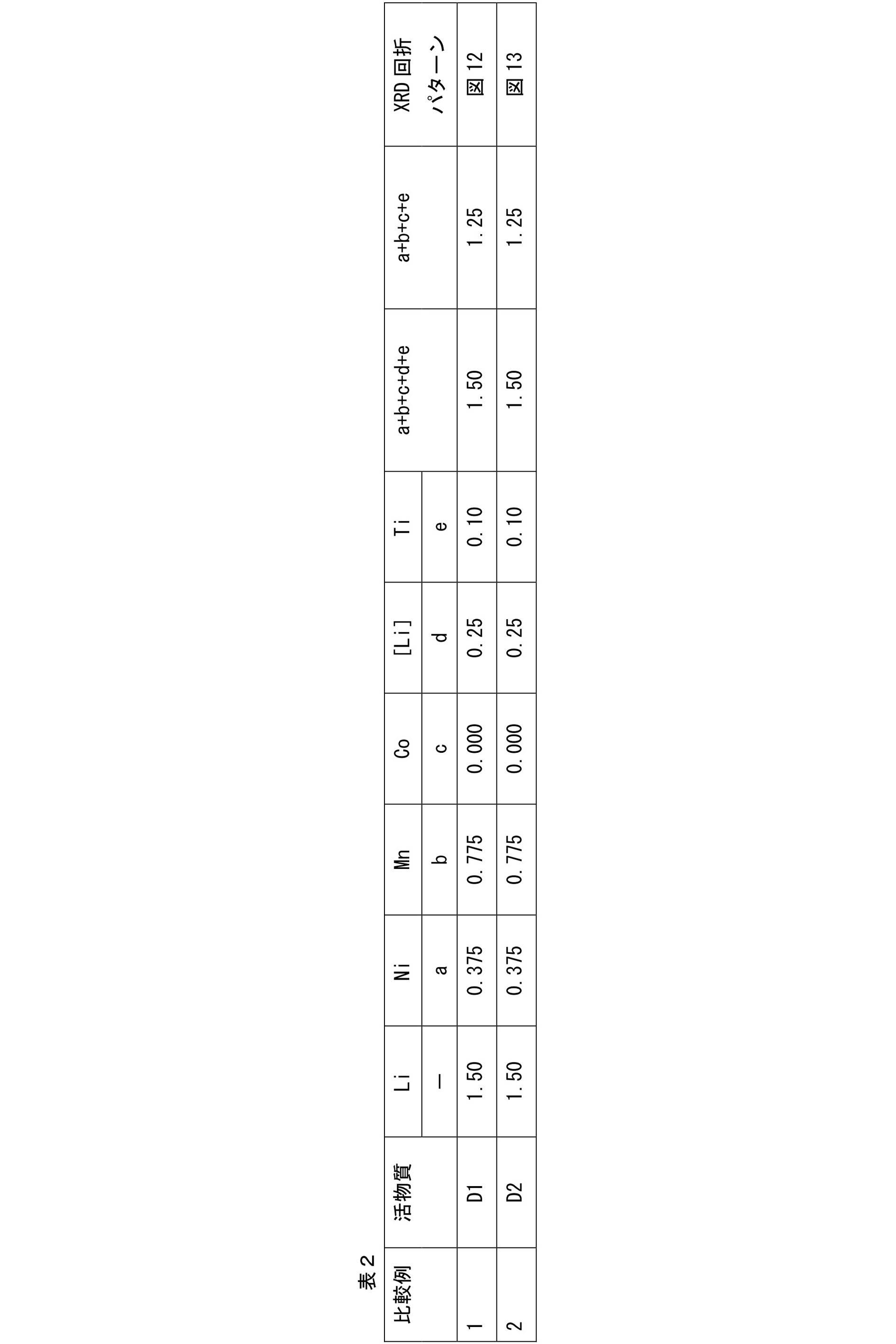


10b 直列積層型電池、
11 負極集電体、
11a 最外層負極集電体、
12 負極活物質層、
13 電解質層、
14 正極集電体、
15 正極活物質層、
16 単電池層、
17 発電要素、
18 負極集電板、
19 正極集電板、
20 負極端子リード、
21 正極端子リード、
22 ラミネートフィルム、
23 集電体、
23a 最外層正極集電体、
23b 最外層負極集電体、
24 双極型電極、
25 シール部(絶縁部)。
Claims (9)
- 下記組成式(1):
Li1.5[NiaMnbCoc[Li]d[X]e]Oz (1)
ここで、Xは、Ti、ZrおよびNbからなる少なくとも1種であり、0.01≦e≦0.7、a+b+c+d+e=1.5、0.1≦d≦0.4、1.1≦[a+b+c+e]≦1.4であり、zは、原子価を満足する酸素数で表される、
を有し、X線回折(XRD)測定において、20-23°、35-40°(101)、42-45°(104)および64-65(108)/65-66(110)に、岩塩型層状構造を示す回折ピークを有する非水電解質二次電池用正極活物質。 - 前記正極活物質が、X線回折(XRD)測定において、35-40°(101)に3つの回折ピークを有し、42-45°(104)に1つの回折ピークを有する請求項1に記載の非水電解質二次電池用正極活物質。
- X線回折(XRD)測定において、20-23°、35.5-36.5°(101)、43.5-44.5°(104)および64-65(108)/65-66(110)に回折ピークを有する、請求項1または2に記載の正極活物質。
- 0.02≦e≦0.5である、請求項1~3のいずれか一項に記載の正極活物質。
- Ti、ZrおよびNbの少なくとも一種のクエン酸塩と、融点が100℃~350℃の遷移金属の有機酸塩とを混合する第1工程と、
第1工程で得られた混合物を100℃~350℃で融解する第2工程と、
第2工程で得られた溶融物を、前記融点以上の温度で熱分解する第3工程と、
第3工程で得られた熱分解物を焼成する第4工程と、
を含む、請求項1~4のいずれか一項に記載の正極活物質の製造方法。 - 第1工程において、さらにアルカリ金属の有機酸塩を混合する請求項5に記載の製造方法。
- 請求項1~4のいずれか一項に記載の正極活物質または請求項5もしくは6に記載の製造方法により製造された正極活物質を含む非水電解質二次電池用正極。
- 請求項7に記載の正極と、
リチウムイオンを挿入・脱離可能な負極活物質を含有する負極と、
前記正極および前記負極の間に介在する電解質層とを備え、
前記負極活物質が、非晶質炭素層で表面が被覆され、鱗片状ではない黒鉛材料からなり、BET比表面積が0.8~1.5m2/gの範囲にあり、タップ密度が0.9~1.2g/cm3の範囲にある、非水電解質二次電池。 - 前記電解液が、
ジメチルカーボネート、ジエチルカーボネート、ジプロピルカーボネート、メチルプロピルカーボネート、エチルプロピルカーボネート、メチルエチルカーボネート、エチレンカーボネート、プロピレンカーボネート、ブチレンカーボネート、含フッ素環状カーボネート、含フッ素鎖状カーボネート、含フッ素鎖状エーテルおよび含フッ素鎖状エステルの少なくとも一種、
LiPF6、および、
有機スルホン系化合物、有機ジスルホン系化合物、ビニレンカーボネート誘導体、エチレンカーボネート誘導体、エステル誘導体、2価フェノール誘導体、テルフェニル誘導体、ホスフェート誘導体およびフルオロリン酸リチウム誘導体の少なくとも一種の電解液用添加剤を含む、請求項8に記載の非水電解質二次電池。
Priority Applications (5)
| Application Number | Priority Date | Filing Date | Title |
|---|---|---|---|
| EP13845202.4A EP2908365B1 (en) | 2012-10-12 | 2013-10-11 | Positive electrode active substance for nonaqueous electrolyte secondary cell, method for producing positive electrode active substance for nonaqueous electrolyte secondary cell, and nonaqueous electrolyte secondary cell |
| KR1020157008595A KR101571274B1 (ko) | 2012-10-12 | 2013-10-11 | 비수 전해질 2차 전지용 정극 활물질, 비수 전해질 2차 전지용 정극 활물질의 제조 방법 및 비수 전해질 2차 전지 |
| JP2014540918A JP6020584B2 (ja) | 2012-10-12 | 2013-10-11 | 非水電解質二次電池用正極活物質の製造方法 |
| CN201380053298.6A CN104704658B (zh) | 2012-10-12 | 2013-10-11 | 非水电解质二次电池用正极活性物质、非水电解质二次电池用正极活性物质的制造方法及非水电解质二次电池 |
| US14/434,412 US20150280210A1 (en) | 2012-10-12 | 2013-10-11 | Positive electrode active material for non-aqueous electrolyte secondary cell, method for producing positive electrode active material for non-aqueous electrolyte secondary cell, and non-aqueous electrolyte secondary cell |
Applications Claiming Priority (2)
| Application Number | Priority Date | Filing Date | Title |
|---|---|---|---|
| JP2012-227383 | 2012-10-12 | ||
| JP2012227383 | 2012-10-12 |
Publications (1)
| Publication Number | Publication Date |
|---|---|
| WO2014058068A1 true WO2014058068A1 (ja) | 2014-04-17 |
Family
ID=50477529
Family Applications (1)
| Application Number | Title | Priority Date | Filing Date |
|---|---|---|---|
| PCT/JP2013/077856 Ceased WO2014058068A1 (ja) | 2012-10-12 | 2013-10-11 | 非水電解質二次電池用正極活物質、非水電解質二次電池用正極活物質の製造方法および非水電解質二次電池 |
Country Status (6)
| Country | Link |
|---|---|
| US (1) | US20150280210A1 (ja) |
| EP (1) | EP2908365B1 (ja) |
| JP (1) | JP6020584B2 (ja) |
| KR (1) | KR101571274B1 (ja) |
| CN (1) | CN104704658B (ja) |
| WO (1) | WO2014058068A1 (ja) |
Cited By (9)
| Publication number | Priority date | Publication date | Assignee | Title |
|---|---|---|---|---|
| JP2014110166A (ja) * | 2012-12-03 | 2014-06-12 | Toyota Motor Corp | 負極活物質およびリチウム電池 |
| WO2015163356A1 (ja) * | 2014-04-22 | 2015-10-29 | 三菱化学株式会社 | 非水二次電池用正極活物質及び非水二次電池 |
| CN105390736A (zh) * | 2014-09-02 | 2016-03-09 | 丰田自动车株式会社 | 非水电解质二次电池 |
| WO2016098215A1 (ja) * | 2014-12-17 | 2016-06-23 | 日産自動車株式会社 | 電気デバイス |
| WO2016108382A1 (ko) * | 2014-12-29 | 2016-07-07 | 삼성에스디아이 주식회사 | 리튬 이차전지용 양극활물질, 그의 제조방법 및 이를 포함한 리튬 이차전지 |
| CN105845902A (zh) * | 2016-04-01 | 2016-08-10 | 济宁市无界科技有限公司 | 熔合法制备锂锰铌复合氧化物锂离子电池正极材料的方法 |
| JP2016225237A (ja) * | 2015-06-03 | 2016-12-28 | オートモーティブエナジーサプライ株式会社 | 二次電池の製造方法 |
| JPWO2017217407A1 (ja) * | 2016-06-13 | 2019-04-11 | 日本電気株式会社 | リチウムイオン二次電池 |
| JP2022505691A (ja) * | 2018-12-29 | 2022-01-14 | フーナン ジンイェ ハイ-テック カンパニー リミテッド | リチウムイオン電池負極材料、リチウムイオン電池負極、リチウムイオン電池、電池パック、及び電池動力車両 |
Families Citing this family (6)
| Publication number | Priority date | Publication date | Assignee | Title |
|---|---|---|---|---|
| CN105259239B (zh) * | 2015-11-04 | 2017-12-19 | 吉林大学 | NiNb2O6为敏感电极的YSZ基混成电位型丙酮传感器及制备方法 |
| WO2017155070A1 (ja) | 2016-03-09 | 2017-09-14 | Dowaエレクトロニクス株式会社 | 溶液およびその製造方法、ならびに二次電池用活物質の製造方法 |
| CN109950474B (zh) * | 2018-06-29 | 2020-04-24 | 宁德时代新能源科技股份有限公司 | 锂离子电池 |
| CN112151789B (zh) * | 2019-06-28 | 2021-10-01 | 宁德时代新能源科技股份有限公司 | 一种正极材料及其制备方法和用途 |
| CN114830394B (zh) * | 2019-12-17 | 2026-01-06 | Tdk株式会社 | 固体电解质及全固体电池 |
| EP4020651A4 (en) * | 2019-12-25 | 2023-05-10 | Ningde Amperex Technology Limited | ELECTROCHEMICAL DEVICE AND ELECTRONIC DEVICE THEREOF |
Citations (8)
| Publication number | Priority date | Publication date | Assignee | Title |
|---|---|---|---|---|
| JP2003303592A (ja) * | 2002-04-10 | 2003-10-24 | Japan Storage Battery Co Ltd | 非水電解液二次電池 |
| US20040081888A1 (en) | 2000-06-22 | 2004-04-29 | The University Of Chicago | Lithium metal oxide electrodes for lithium cells and batteries |
| JP2006093067A (ja) * | 2004-09-27 | 2006-04-06 | Kusaka Rare Metal Products Co Ltd | リチウム二次電池用正極活物質及びその製造方法 |
| JP2006164758A (ja) * | 2004-12-07 | 2006-06-22 | Seimi Chem Co Ltd | リチウム二次電池用正極材料 |
| JP2007242581A (ja) * | 2006-02-08 | 2007-09-20 | Sanyo Electric Co Ltd | 非水電解質二次電池 |
| JP2008127233A (ja) * | 2006-11-20 | 2008-06-05 | National Institute Of Advanced Industrial & Technology | チタン及びニッケル含有リチウムマンガン系複合酸化物 |
| WO2011114534A1 (ja) * | 2010-03-19 | 2011-09-22 | トヨタ自動車株式会社 | リチウム二次電池および該リチウム二次電池用正極活物質 |
| JP2012003879A (ja) * | 2010-06-15 | 2012-01-05 | Ngk Insulators Ltd | リチウム二次電池の正極活物質用の板状粒子、及び同物質膜、並びにリチウム二次電池 |
Family Cites Families (10)
| Publication number | Priority date | Publication date | Assignee | Title |
|---|---|---|---|---|
| JP4273568B2 (ja) | 1999-05-14 | 2009-06-03 | 堺化学工業株式会社 | リチウムマンガン複合酸化物粒子状組成物とその製造とリチウムイオン二次電池への利用 |
| JP4945029B2 (ja) * | 2001-03-06 | 2012-06-06 | 新日鐵化学株式会社 | リチウム二次電池負極用材料とその製造方法およびリチウム二次電池 |
| US20090127520A1 (en) * | 2003-05-28 | 2009-05-21 | Pamela Whitfield | Lithium metal oxide compositions |
| JP5451228B2 (ja) | 2008-07-25 | 2014-03-26 | 三井金属鉱業株式会社 | 層構造を有するリチウム遷移金属酸化物 |
| JP5675128B2 (ja) * | 2009-08-28 | 2015-02-25 | 三洋電機株式会社 | リチウムイオン二次電池 |
| JP5485065B2 (ja) * | 2010-07-30 | 2014-05-07 | 三洋電機株式会社 | 非水電解質二次電池 |
| EP2421077B1 (en) * | 2010-08-17 | 2013-10-23 | Umicore | Positive electrode materials combining high safety and high power in a Li rechargeable battery |
| JP5928445B2 (ja) * | 2011-03-07 | 2016-06-01 | 旭硝子株式会社 | リチウムイオン二次電池用の正極活物質およびその製造方法 |
| WO2015049796A1 (ja) * | 2013-10-04 | 2015-04-09 | 日産自動車株式会社 | 非水電解質二次電池用正極活物質およびその製造方法 |
| US9680150B2 (en) * | 2014-01-24 | 2017-06-13 | Nissan Motor Co., Ltd. | Electrical device |
-
2013
- 2013-10-11 EP EP13845202.4A patent/EP2908365B1/en not_active Not-in-force
- 2013-10-11 CN CN201380053298.6A patent/CN104704658B/zh not_active Expired - Fee Related
- 2013-10-11 WO PCT/JP2013/077856 patent/WO2014058068A1/ja not_active Ceased
- 2013-10-11 KR KR1020157008595A patent/KR101571274B1/ko not_active Expired - Fee Related
- 2013-10-11 US US14/434,412 patent/US20150280210A1/en not_active Abandoned
- 2013-10-11 JP JP2014540918A patent/JP6020584B2/ja not_active Expired - Fee Related
Patent Citations (8)
| Publication number | Priority date | Publication date | Assignee | Title |
|---|---|---|---|---|
| US20040081888A1 (en) | 2000-06-22 | 2004-04-29 | The University Of Chicago | Lithium metal oxide electrodes for lithium cells and batteries |
| JP2003303592A (ja) * | 2002-04-10 | 2003-10-24 | Japan Storage Battery Co Ltd | 非水電解液二次電池 |
| JP2006093067A (ja) * | 2004-09-27 | 2006-04-06 | Kusaka Rare Metal Products Co Ltd | リチウム二次電池用正極活物質及びその製造方法 |
| JP2006164758A (ja) * | 2004-12-07 | 2006-06-22 | Seimi Chem Co Ltd | リチウム二次電池用正極材料 |
| JP2007242581A (ja) * | 2006-02-08 | 2007-09-20 | Sanyo Electric Co Ltd | 非水電解質二次電池 |
| JP2008127233A (ja) * | 2006-11-20 | 2008-06-05 | National Institute Of Advanced Industrial & Technology | チタン及びニッケル含有リチウムマンガン系複合酸化物 |
| WO2011114534A1 (ja) * | 2010-03-19 | 2011-09-22 | トヨタ自動車株式会社 | リチウム二次電池および該リチウム二次電池用正極活物質 |
| JP2012003879A (ja) * | 2010-06-15 | 2012-01-05 | Ngk Insulators Ltd | リチウム二次電池の正極活物質用の板状粒子、及び同物質膜、並びにリチウム二次電池 |
Non-Patent Citations (1)
| Title |
|---|
| See also references of EP2908365A4 |
Cited By (16)
| Publication number | Priority date | Publication date | Assignee | Title |
|---|---|---|---|---|
| JP2014110166A (ja) * | 2012-12-03 | 2014-06-12 | Toyota Motor Corp | 負極活物質およびリチウム電池 |
| JPWO2015163356A1 (ja) * | 2014-04-22 | 2017-04-20 | 三菱化学株式会社 | 非水二次電池用正極活物質及び非水二次電池 |
| WO2015163356A1 (ja) * | 2014-04-22 | 2015-10-29 | 三菱化学株式会社 | 非水二次電池用正極活物質及び非水二次電池 |
| JP2019165010A (ja) * | 2014-04-22 | 2019-09-26 | 三菱ケミカル株式会社 | 非水二次電池 |
| CN105390736A (zh) * | 2014-09-02 | 2016-03-09 | 丰田自动车株式会社 | 非水电解质二次电池 |
| JP2016054026A (ja) * | 2014-09-02 | 2016-04-14 | トヨタ自動車株式会社 | 非水電解液二次電池 |
| US9929404B2 (en) | 2014-09-02 | 2018-03-27 | Toyota Jidosha Kabushiki Kaisha | Non-aqueous electrolyte secondary battery |
| WO2016098215A1 (ja) * | 2014-12-17 | 2016-06-23 | 日産自動車株式会社 | 電気デバイス |
| JPWO2016098215A1 (ja) * | 2014-12-17 | 2017-10-19 | 日産自動車株式会社 | 電気デバイス |
| WO2016108382A1 (ko) * | 2014-12-29 | 2016-07-07 | 삼성에스디아이 주식회사 | 리튬 이차전지용 양극활물질, 그의 제조방법 및 이를 포함한 리튬 이차전지 |
| JP2016225237A (ja) * | 2015-06-03 | 2016-12-28 | オートモーティブエナジーサプライ株式会社 | 二次電池の製造方法 |
| CN105845902A (zh) * | 2016-04-01 | 2016-08-10 | 济宁市无界科技有限公司 | 熔合法制备锂锰铌复合氧化物锂离子电池正极材料的方法 |
| CN105845902B (zh) * | 2016-04-01 | 2019-01-11 | 济宁市无界科技有限公司 | 熔合法制备锂锰铌复合氧化物锂离子电池正极材料的方法 |
| JPWO2017217407A1 (ja) * | 2016-06-13 | 2019-04-11 | 日本電気株式会社 | リチウムイオン二次電池 |
| JP2022505691A (ja) * | 2018-12-29 | 2022-01-14 | フーナン ジンイェ ハイ-テック カンパニー リミテッド | リチウムイオン電池負極材料、リチウムイオン電池負極、リチウムイオン電池、電池パック、及び電池動力車両 |
| JP7161045B2 (ja) | 2018-12-29 | 2022-10-25 | フーナン ジンイェ ハイ-テック カンパニー リミテッド | リチウムイオン電池負極材料およびその製造方法 |
Also Published As
| Publication number | Publication date |
|---|---|
| CN104704658A (zh) | 2015-06-10 |
| US20150280210A1 (en) | 2015-10-01 |
| JP6020584B2 (ja) | 2016-11-02 |
| EP2908365B1 (en) | 2017-05-03 |
| KR101571274B1 (ko) | 2015-11-23 |
| JPWO2014058068A1 (ja) | 2016-09-05 |
| CN104704658B (zh) | 2017-06-30 |
| KR20150053942A (ko) | 2015-05-19 |
| EP2908365A1 (en) | 2015-08-19 |
| EP2908365A4 (en) | 2015-12-16 |
Similar Documents
| Publication | Publication Date | Title |
|---|---|---|
| JP6020584B2 (ja) | 非水電解質二次電池用正極活物質の製造方法 | |
| JP6288941B2 (ja) | 固溶体活物質を含む正極活物質、該正極活物質を含む正極、および該正極を用いた非水電解質二次電池 | |
| CN104508893B (zh) | 非水系有机电解液二次电池 | |
| KR20190041715A (ko) | 리튬 이차전지용 양극재, 이의 제조방법, 이를 포함하는 리튬 이차전지용 양극 및 리튬 이차전지 | |
| JP2020525993A (ja) | リチウム二次電池用正極活物質、その製造方法、それを含むリチウム二次電池用正極及びリチウム二次電池 | |
| WO2015049796A1 (ja) | 非水電解質二次電池用正極活物質およびその製造方法 | |
| WO2014203621A1 (ja) | 非水電解質二次電池 | |
| JP2014017199A (ja) | リチウム二次電池用電極およびその製造方法並びにリチウム二次電池およびその製造方法 | |
| CN105934840B (zh) | 电器件 | |
| JP2021163542A (ja) | 非水電解質二次電池 | |
| WO2015111194A1 (ja) | 電気デバイス | |
| KR20190113441A (ko) | 리튬 이차전지용 양극 활물질, 이의 제조방법, 이를 포함하는 리튬 이차전지용 양극 및 리튬 이차전지 | |
| JP6269158B2 (ja) | 非水電解質二次電池用正極活物質およびその製造方法 | |
| JP6269157B2 (ja) | 非水電解質二次電池用正極活物質およびその製造方法 | |
| JP6380553B2 (ja) | 電気デバイス | |
| JP6640438B2 (ja) | 非水電解質二次電池用正極活物質およびその製造方法 | |
| JP6640439B2 (ja) | 非水電解質二次電池用正極活物質およびその製造方法 | |
| JP6962015B2 (ja) | 電気デバイス | |
| JP6252603B2 (ja) | 電気デバイス | |
| KR102809638B1 (ko) | 양극 활물질, 이를 포함하는 양극 및 양극을 포함하는 리튬 이차전지 | |
| JP2013191381A (ja) | 平板積層型電池およびその製造方法 |
Legal Events
| Date | Code | Title | Description |
|---|---|---|---|
| 121 | Ep: the epo has been informed by wipo that ep was designated in this application |
Ref document number: 13845202 Country of ref document: EP Kind code of ref document: A1 |
|
| ENP | Entry into the national phase |
Ref document number: 2014540918 Country of ref document: JP Kind code of ref document: A Ref document number: 20157008595 Country of ref document: KR Kind code of ref document: A |
|
| REEP | Request for entry into the european phase |
Ref document number: 2013845202 Country of ref document: EP |
|
| WWE | Wipo information: entry into national phase |
Ref document number: 14434412 Country of ref document: US Ref document number: 2013845202 Country of ref document: EP |
|
| NENP | Non-entry into the national phase |
Ref country code: DE |