WO2014061428A1 - 観察装置、観察支援装置、観察支援方法及びプログラム - Google Patents
観察装置、観察支援装置、観察支援方法及びプログラム Download PDFInfo
- Publication number
- WO2014061428A1 WO2014061428A1 PCT/JP2013/076398 JP2013076398W WO2014061428A1 WO 2014061428 A1 WO2014061428 A1 WO 2014061428A1 JP 2013076398 W JP2013076398 W JP 2013076398W WO 2014061428 A1 WO2014061428 A1 WO 2014061428A1
- Authority
- WO
- WIPO (PCT)
- Prior art keywords
- unit
- positional relationship
- information
- inserted body
- observation
- Prior art date
- Legal status (The legal status is an assumption and is not a legal conclusion. Google has not performed a legal analysis and makes no representation as to the accuracy of the status listed.)
- Ceased
Links
Images











Classifications
-
- A—HUMAN NECESSITIES
- A61—MEDICAL OR VETERINARY SCIENCE; HYGIENE
- A61B—DIAGNOSIS; SURGERY; IDENTIFICATION
- A61B1/00—Instruments for performing medical examinations of the interior of cavities or tubes of the body by visual or photographical inspection, e.g. endoscopes; Illuminating arrangements therefor
- A61B1/005—Flexible endoscopes
- A61B1/009—Flexible endoscopes with bending or curvature detection of the insertion part
-
- A—HUMAN NECESSITIES
- A61—MEDICAL OR VETERINARY SCIENCE; HYGIENE
- A61B—DIAGNOSIS; SURGERY; IDENTIFICATION
- A61B1/00—Instruments for performing medical examinations of the interior of cavities or tubes of the body by visual or photographical inspection, e.g. endoscopes; Illuminating arrangements therefor
- A61B1/00002—Operational features of endoscopes
- A61B1/00004—Operational features of endoscopes characterised by electronic signal processing
-
- A—HUMAN NECESSITIES
- A61—MEDICAL OR VETERINARY SCIENCE; HYGIENE
- A61B—DIAGNOSIS; SURGERY; IDENTIFICATION
- A61B1/00—Instruments for performing medical examinations of the interior of cavities or tubes of the body by visual or photographical inspection, e.g. endoscopes; Illuminating arrangements therefor
- A61B1/00002—Operational features of endoscopes
- A61B1/00004—Operational features of endoscopes characterised by electronic signal processing
- A61B1/00006—Operational features of endoscopes characterised by electronic signal processing of control signals
-
- A—HUMAN NECESSITIES
- A61—MEDICAL OR VETERINARY SCIENCE; HYGIENE
- A61B—DIAGNOSIS; SURGERY; IDENTIFICATION
- A61B1/00—Instruments for performing medical examinations of the interior of cavities or tubes of the body by visual or photographical inspection, e.g. endoscopes; Illuminating arrangements therefor
- A61B1/00147—Holding or positioning arrangements
-
- G—PHYSICS
- G02—OPTICS
- G02B—OPTICAL ELEMENTS, SYSTEMS OR APPARATUS
- G02B23/00—Telescopes, e.g. binoculars; Periscopes; Instruments for viewing the inside of hollow bodies; Viewfinders; Optical aiming or sighting devices
- G02B23/24—Instruments or systems for viewing the inside of hollow bodies, e.g. fibrescopes
- G02B23/2476—Non-optical details, e.g. housings, mountings, supports
-
- A—HUMAN NECESSITIES
- A61—MEDICAL OR VETERINARY SCIENCE; HYGIENE
- A61B—DIAGNOSIS; SURGERY; IDENTIFICATION
- A61B34/00—Computer-aided surgery; Manipulators or robots specially adapted for use in surgery
- A61B34/20—Surgical navigation systems; Devices for tracking or guiding surgical instruments, e.g. for frameless stereotaxis
- A61B2034/2046—Tracking techniques
- A61B2034/2061—Tracking techniques using shape-sensors, e.g. fiber shape sensors with Bragg gratings
-
- A—HUMAN NECESSITIES
- A61—MEDICAL OR VETERINARY SCIENCE; HYGIENE
- A61B—DIAGNOSIS; SURGERY; IDENTIFICATION
- A61B6/00—Apparatus or devices for radiation diagnosis; Apparatus or devices for radiation diagnosis combined with radiation therapy equipment
- A61B6/12—Arrangements for detecting or locating foreign bodies
-
- A—HUMAN NECESSITIES
- A61—MEDICAL OR VETERINARY SCIENCE; HYGIENE
- A61B—DIAGNOSIS; SURGERY; IDENTIFICATION
- A61B8/00—Diagnosis using ultrasonic, sonic or infrasonic waves
- A61B8/08—Clinical applications
- A61B8/0833—Clinical applications involving detecting or locating foreign bodies or organic structures
- A61B8/0841—Clinical applications involving detecting or locating foreign bodies or organic structures for locating instruments
Definitions
- the present invention relates to an observation apparatus for inserting and observing an insertion portion inside an inserted body, an observation support apparatus used for such an observation apparatus, an observation support method, and a program for causing a computer to execute the procedure of the observation support apparatus.
- Patent Document 1 As an assisting device for observing by inserting the insertion portion into the inserted body, for example, in Patent Document 1, when inserting the endoscope insertion portion into a human body, the shape of the endoscope insertion portion is displayed on the display portion.
- the structure which displays is disclosed.
- a plurality of flexible bending detection optical fibers each having a bending detection portion whose amount of light transmission changes in accordance with the angle of the bent angle is formed into a flexible belt-shaped member. It is attached in a state where it is arranged in parallel, and it is inserted and arranged over almost the entire length in the endoscope insertion part, and the bending state of the belt-like member in the part where each bending detection part is located from the light transmission amount of each bending detection optical fiber. The bending state is detected and the bending state of the endoscope insertion portion is displayed on the monitor screen.
- Patent Document 1 can present the shape of the insertion portion inside the inserted body that cannot be seen from the outside of the inserted body when inserted into the inserted body. However, it has not been proposed to detect which part of the inserted body is imaged (observed) and to display it.
- the present invention has been made in view of the above points, and is an observation device, an observation support device, an observation support method, and an observation device that can provide information to the operator for determining where in the body to be imaged.
- the purpose is to provide a program.
- an insertion unit that is inserted into the inserted body, an imaging unit that is disposed in the insertion unit and images the inserted body, and obtains insertion state information of the insertion unit
- An insertion state acquisition unit that receives the shape information of the inserted body, and the insertion state information and the shape information of the inserted body.
- An observation apparatus includes a positional relationship calculation unit that calculates a positional relationship and an output unit that outputs the calculation result of the positional relationship calculation unit as display information.
- the insertion state information of the insertion section is obtained.
- An insertion state acquisition unit to be acquired, an inserted body shape acquisition unit for acquiring shape information of the inserted body, the insertion state information and the inserted body shape information are input, and the insertion unit for the inserted body
- an observation support apparatus that includes a positional relationship calculation unit that calculates the positional relationship and an output unit that outputs the calculation result of the positional relationship calculation unit as display information.
- the insertion state information of the insertion section is acquired.
- an observation support method having a positional relationship calculation step for calculating a positional relationship, and an output step for outputting the calculation result of the positional relationship calculation step as display information.
- An acquisition procedure, an insertion object shape acquisition procedure for acquiring shape information of the insertion object, the insertion state information and the insertion object shape information are input, and the positional relationship of the insertion portion with respect to the insertion object is determined.
- the present invention it is possible to provide information for determining where in the body to be imaged, so that it is possible to image which part in the body to be imaged and all necessary portions. Therefore, it is possible to provide an observation apparatus, an observation support apparatus, an observation support method, and a program that can make it possible for the operator to easily determine whether or not an observation point is overlooked.
- FIG. 1A is a diagram illustrating a schematic configuration of an observation apparatus to which the observation support apparatus according to the first embodiment of the present invention is applied.
- FIG. 1B is a block configuration diagram of the observation support apparatus according to the first embodiment.
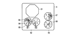
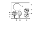
- FIG. 1C is a diagram for explaining an example of providing information via a display device connected to the observation support device according to the first embodiment.
- FIG. 2A is a diagram illustrating a schematic configuration of a rigid endoscope apparatus as an insertion tool in the observation apparatus according to the first embodiment.
- FIG. 2B is a perspective view of the distal end of the insertion portion.
- FIG. 3A is a diagram for explaining a configuration of an insertion / rotation detection unit.
- FIG. 3B is a diagram for explaining the operation principle of the insertion / rotation detection unit.
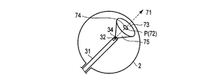
- FIG. 4 is a diagram illustrating an insertion state of the insertion portion into the inserted body.
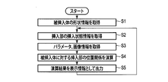
- FIG. 5 is a diagram illustrating an operation flowchart of the observation support apparatus according to the first embodiment.
- FIG. 6A is a diagram for explaining where the first position display shows in the inserted body.
- FIG. 6B is a diagram for explaining where the second position display shows in the inserted body.
- FIG. 7A is a diagram for explaining a display example when an insertion part is inserted into an insertion object with a branch.
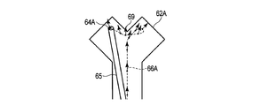
- FIG. 7B is a diagram for explaining another display example.
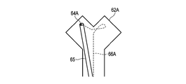
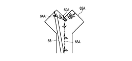
- FIG. 7C is a diagram for explaining still another display example.
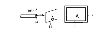
- FIG. 8A is a diagram illustrating a state before rotation for explaining a change in a captured image due to rotation of the insertion unit.
- FIG. 8A is a diagram illustrating a state before rotation for explaining a change in a captured image due to rotation of the insertion unit.
- FIG. 8B is a diagram illustrating a state after rotation for explaining a change in a captured image due to rotation of the insertion unit.
- FIG. 9 is a diagram showing a schematic configuration of a flexible endoscope apparatus as an insertion tool in the observation apparatus according to the second embodiment of the present invention.
- FIG. 10 is a diagram illustrating an insertion state of the insertion portion into the inserted body.
- FIG. 11 is a diagram illustrating a schematic configuration of an observation apparatus according to the second embodiment.
- FIG. 12A is a diagram illustrating a case where the bending portion is bent in the upward direction on the paper surface for explaining the principle of the fiber shape sensor.
- FIG. 12B is a diagram illustrating a case where the bending portion is not curved for explaining the principle of the fiber shape sensor.
- FIG. 12C is a diagram illustrating a case where the bending portion is bent downward in the drawing for explaining the principle of the fiber shape sensor.
- FIG. 13 is a diagram showing a structure for attaching the fiber shape sensor to the insertion portion.
- FIG. 14 is a block diagram of an observation support apparatus according to the third embodiment.
- FIG. 15 is a diagram illustrating an operation flowchart of the observation support apparatus according to the third embodiment.
- FIG. 16 is a diagram for explaining an example of providing information in the observation apparatus according to the third embodiment.
- FIG. 17 is a diagram for explaining another example of a form of providing information.
- FIG. 18 is a diagram for explaining still another example of a form of providing information.
- the observation apparatus 1 includes an insertion unit 31 that is inserted into the inserted body 2 and an imaging unit 32 that images the inserted body 2. 3, the insertion / rotation detection unit 4 as a detection unit that detects displacement amount information of the insertion unit 31, and the insertion state information of the insertion unit 31 from the displacement amount information from the insertion / rotation detection unit 4, According to the first embodiment of the present invention, the positional relationship of the insertion portion 31 with respect to the insertion object 2 is calculated based on the insertion state information and the shape information of the insertion object 2, and the calculation result is output as display information. It is comprised from the observation assistance apparatus 5 and the display apparatus 6 which displays display information.
- the insertion tool 3 is, for example, a rigid endoscope apparatus as shown in FIG. 2A, and includes an insertion portion 31 and an operation portion 33 configured integrally with the insertion portion 31.
- the insertion portion 31 is a rigid tubular member, and can be inserted into the inserted body 2 from the insertion port 21 of the inserted body 2. Note that the inside of the insertion object 2 is filled with a predetermined material such as air, physiological saline, or a chemical solution.
- an imaging opening 34 is provided at the end of the insertion portion 31 in the insertion direction (hereinafter referred to as the insertion portion distal end), and in the vicinity of the insertion portion distal end inside the insertion portion 31.
- an imaging unit 32 is built in. The light incident on the imaging opening 34 is received by the imaging unit 32 and imaged. An image captured by the imaging unit 32 is output to the display device 6 through the observation support device 5 according to the first embodiment.
- the imaging unit 32 is disposed not in the vicinity of the distal end of the insertion unit inside the insertion unit 31 but in the operation unit 33, and is connected to the imaging opening 34 by a light guide or the like, and is incident on the imaging opening 34.
- the image may be guided to the imaging unit 32 to perform imaging.
- the insertion portion 31 has an illumination optical fiber, guides light from an illumination light source (not shown) disposed in the operation portion 33, and inserts the insertion portion 31.
- the light is emitted from the tip light supply unit 35 as illumination light for imaging.
- a treatment opening 36 is provided at the distal end of the insertion portion, and a treatment instrument inserted through the insertion portion 31 from the operation portion 33 can be extended out of the insertion portion 31 from the treatment opening 36. Yes.
- the insertion / rotation detection unit 4 is installed in the vicinity of the insertion port 21 of the inserted body 2, detects the insertion amount and the rotation amount of the insertion unit 31, and as one of the displacement amount information of the insertion unit 31, Output to the observation support device 5.
- the insertion / rotation detection unit 4 includes a light source 41, a light projection lens 42, a light reception lens 43, an optical pattern detection unit 44, and a displacement amount calculation unit 45, as shown in FIG. 3A.
- the light emitted from the light source 41 is applied to the insertion unit 31 through the light projecting lens 42, and the light reflected by the insertion unit 31 is received by the optical pattern detection unit 44 through the light receiving lens 43.
- the optical pattern detection unit 44 continuously detects the image of the insertion unit 31 surface, which is an optical pattern, with detection times t 0 , t 1 , t 2 ,..., T n ,.
- the displacement amount calculation unit 45 is an arbitrarily selected reference pattern that exists in an image (optical pattern PT n ) of image data captured at an arbitrary time t n by the optical pattern detection unit 44. alpha and, this time t n of the image data captured to a time t n + 1 after the lapse of an arbitrary time from the image (optical pattern PT n + 1) optical pattern consistent with the reference pattern alpha present in part of the alpha '
- the displacements on the image data are compared, and the displacement amounts on the images in the x-axis direction and the y-axis direction are calculated.
- FIG. 3B the displacement amount calculation unit 45 is an arbitrarily selected reference pattern that exists in an image (optical pattern PT n ) of image data captured at an arbitrary time t n by the optical pattern detection unit 44. alpha and, this time t n of the image data captured to a time t n + 1 after the lapse of an arbitrary time from the image (optical pattern PT
- the optical pattern detection unit 44 is positioned so that the x-axis of the optical pattern detection unit 44 coincides with the axial direction of the insertion unit 31. Therefore, the displacement amount ⁇ x f in the x-axis direction calculated by the displacement amount calculation unit 45 is proportional to the insertion amount of the insertion unit 31, and the displacement amount ⁇ y f in the y-axis direction is proportional to the rotation amount of the insertion unit 31.
- the displacement amount (insertion amount and rotation amount) on the image calculated by the displacement amount calculation unit 45 is output to the observation support device 5 as displacement amount information.
- the displacement amount information also includes information on the insertion direction and the rotation direction.
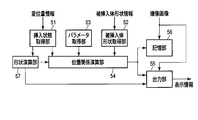
- the observation support apparatus 5 includes an insertion state acquisition unit 51, an inserted body shape acquisition unit 52, a parameter acquisition unit 53, a positional relationship calculation unit 54, an output unit 55, and The storage unit 56 is configured.
- the insertion state acquisition unit 51 inserts at least part of the insertion unit 31 into the inserted body 2 based on the displacement amount information output from the displacement amount calculation unit 45 of the insertion / rotation detection unit 4. For example, the position and orientation of a certain point of the insertion unit 31 are acquired.
- the inserted object shape acquisition unit 52 acquires the shape information (inserted object shape information) of the inserted object 2.
- the inserted body shape information is configured based on data from the outside or the inside of the inserted body 2 before the insertion portion 31 is inserted into the inserted body 2.
- the insertion object shape information based on data from the outside uses, for example, a CT diagnostic apparatus, an ultrasonic diagnostic apparatus, an X-ray apparatus, or the like that can be detected by being transmitted through the insertion object 2. Configured.
- the inserted object shape information based on the data from the inside uses the trajectory data when the insertion part 31 is moved in the space of the inserted object 2 or when the tip of the insertion part contacts the inserted object 2. It is configured by connecting position information. If position information at the time of contact between the distal end of the insertion portion and the inserted body 2 is used, the size of the space can be detected, and more accurate inserted body shape information can be acquired.
- the to-be-inserted body 2 is a human internal organ, it can comprise by estimating from a physique, and when the to-be-inserted body 2 is a structure, it can also comprise by inputting a shape with drawing. .
- the acquisition of the inserted body shape information by the inserted body shape acquisition unit 52 may be performed by connecting a device constituting the inserted body shape information such as a CT diagnostic apparatus and directly acquiring the information.
- the inserted object shape information output from the apparatus may be temporarily stored in a storage medium, and the stored inserted object shape information may be read out or downloaded via a network and acquired. Absent.
- the insertion object shape acquisition unit 52 is not limited to such an interface or data reader, and may itself be a device that constitutes the insertion object shape information.
- the parameter acquisition unit 53 includes, for example, the angle of view information (such as the focal length of the lens) of the imaging unit 32 and the refractive index of a predetermined material such as air or a chemical solution interposed between the distal end of the insertion unit and the inserted body 2.
- the parameter used for the calculation in the positional relationship calculation unit 54 is acquired.
- the parameter acquisition unit 53 may acquire such parameters by inputting them from the outside, or may store them in advance.
- the positional relationship calculation unit 54 stores the known shape information of the insertion unit 31 stored in advance, the insertion state information acquired by the insertion state acquisition unit 51, and the insertion target acquired by the insertion target shape acquisition unit 52. Based on the shape information, the parameters acquired by the parameter acquisition unit 53, and the image (captured image) captured by the imaging unit 32, the positional relationship of the insertion unit 31 with respect to the insertion object 2, that is, the insertion unit 31. It is calculated which part in the inserted body 2 is directed to the whole or the tip.
- the positional relationship calculation unit 54 first calculates the position of the distal end of the insertion unit based on the shape information and insertion state information of the insertion unit 31, and takes a captured image in the same manner as the insertion / rotation detection unit 4. From the movement of the inner optical pattern, the movement amount and movement direction of the insertion portion tip, that is, the direction (axial direction) in which the insertion portion tip faces is calculated. At the time of this calculation, correction is performed using the parameters acquired by the parameter acquisition unit 53. Then, based on the calculation result and the inserted body shape information, the intersection point between the direction in which the distal end of the insertion portion faces and the inserted body 2 is calculated. That is, as shown in FIG.
- the positional relationship calculation unit 58 has an intersection 72 between the straight line formed in the direction in which the distal end of the insertion unit faces (imaging direction 71) and the shape of the inserted body 2, that is, the visual field (imaging region). 73) The center is obtained as the imaging position P.
- the imaging unit 32 captures an image from the distance between the position of the distal end of the insertion unit and the imaging surface of the inserted body 2 based on the inserted body shape information.
- the field of view (imaging area 73) that is the area of the inserted object 2 that is inserted may be calculated as the imaging position P.
- imaging is performed more accurately by using parameters such as the refractive index of a predetermined material interposed between the insertion unit 31 and the inserted body 2 and the angle of view information (lens focal length, etc.) of the imaging unit 32.
- Region 73 can be determined.
- the imaging region 73 as the imaging position P, the range captured by the imaging unit 32 can be grasped.
- a partial region 74 or a point in the field of view (imaging region 73) may be calculated as the imaging position P. For example, when the imaging region 73 cannot be accurately detected, it is possible to prevent erroneous detection that a non-imaging range has been captured by calculating a small region in consideration of the error. That is, observation omission can be prevented.
- the positional relationship calculation unit 54 outputs imaging position information indicating the imaging position P thus obtained to the output unit 55 and the storage unit 56.
- the output unit 55 indicates the calculation result of the positional relationship calculation unit 54, that is, the imaging position information indicating the imaging position P (for example, the intersection 72). Display information to be displayed on the display device 6 in a form that can be determined by the operator is created and output to the display device 6.
- the storage unit 56 stores at least a part of the calculation result of the positional relationship calculation unit 54 and, if necessary, the captured image.
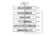
- the insertion object shape acquisition unit 52 acquires the insertion object shape information (step S1). Thereafter, the insertion state acquisition unit 51 acquires the insertion state information of the insertion unit 31 into the inserted body 2 (step S2). And the parameter from the parameter acquisition part 53 and the captured image from the imaging part 32 are acquired by the positional relationship calculating part 54 (step S3), these to-be-inserted body shape information, insertion state information, a parameter, and a captured image Based on the above, the positional relationship of the insertion portion 31 with respect to the insertion object 2 is calculated (step S4). Thereafter, the calculation result is stored in the storage unit 56 and output by the output unit 55 (step S5). Then, returning to step S2, the operations of steps S2 to S5 are repeated.
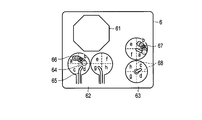
- the output unit 55 is a two-dimensional diagram 62 obtained by dividing the captured image (captured image display 61) from the imaging unit 32 and the inserted object 2 as the inserted object shape information at a predetermined location. 63 is generated and output so as to be displayed on the display device 6. Further, on the two-dimensional diagrams 62 and 63 obtained by dividing the inserted body 2 by a predetermined portion, the imaging position P, that is, the intersection 72 between the inserted body 2 and the axial direction (imaging direction 71) of the distal end of the insertion portion is concerned. Create display information that displays information.
- the first two-dimensional diagram 62 is a diagram showing a state in which the shape of the insertion object 2 is divided by the YZ plane in the coordinates of the insertion object 2 and opened left and right.
- the second two-dimensional diagram 63 is a view of a different viewpoint from the first two-dimensional diagram 62.
- FIG. It is a figure which shows the state opened by dividing by and opened up and down. Then, the output unit 55 creates display information such that the current position display 64 is displayed as information related to the imaging position P on these two-dimensional diagrams 62 and 63.
- the current position display 64 may be the intersection 72 itself between the inserted body 2 and the axial direction of the distal end of the insertion portion. However, as described above, the imaging region 73 is used, or for example, the intersection 72 is centered. It is easier to visually recognize a certain range such as a partial region 74 in the imaging region.
- the output unit 55 may display information such that an insertion portion shape schematic display 65 indicating the shape of the insertion unit 31 is displayed in addition to the current position display 64 as information relating to the current imaging position P. it can. That is, the position of the distal end of the insertion portion is calculated by the positional relationship calculation unit 54 as described above, and the shape information of the insertion portion 31 is known, so what is the insertion state of the insertion portion 31 in the inserted body 2.
- the insertion portion shape outline display 65 can be performed.
- the output unit 55 can also use the calculation result stored in the storage unit 56 as display information such that the position locus display 66 is displayed.
- the position locus display 66 also has a certain range.
- some sort of identification display is performed such as changing the color, density, or pattern of each other, or making the position locus display 66 blink. It is desirable to use display information. The presence / absence of the identification display and the form of the identification display may be selectable by the operator.
- a function that allows the operator to perform marking 67 may be added to a place that has already been observed or a place that needs to be observed in the future or again.
- information on the part is stored in the storage unit 56, and the display information is changed so that the output unit 55 displays the marking 67 at the part.
- the location of the marking 67 may be fixed to any one of the intersection 72, the imaging region 73, and a partial region 74 in the imaging region, or may be arbitrarily set by the operator.
- the storage if not only the information of the marked portion 67 but also the insertion direction of the insertion portion 31 is stored together, it can be used for confirmation after observation, observation in the same state next time, or the like. it can. If you can set and store information for specifying which part is the observed part, the re-observation part, and the required treatment part, the display form will be color and shape accordingly. By changing, the operator can easily determine the meaning of each marking 67.
- a pointing device or a visual recognition device is connected to the observation support device 5, and an operator captures an arbitrary range on the captured image display 61 or the two-dimensional diagrams 62 and 63 displayed on the display device 6. A point may be specified.
- the area division display 68 is performed. This is one in which two or more areas are divided by a common theory or regulation of an academic society, an area used as a standard, or a predetermined division method. If it does in this way, it will become easy for an operator to determine which part of the to-be-inserted body 2 is.
- the insertion / rotation detection unit 4 optically detects the shape of the insertion unit 31 with respect to the insertion target 2 and the position and orientation of the imaging opening 34 as described above. May be.
- a coil is provided at least in the vicinity of the imaging opening 34 inside the insertion portion 31, and a magnetic field is generated by passing a current through the coil, and this magnetic field is received outside, or a magnetic field distribution generated outside is coiled.
- the position and orientation of the coil, that is, the imaging opening 34 can be detected.
- the insertion state acquisition unit 51 inserts (at least a part of) the insertion unit 31 inserted into the insertion target body 2 (into the insertion target body 2).
- Information for example, the position / orientation of a point (insertion tip)
- the shape information of the insertion target 2 is acquired by the insertion target shape acquisition unit 52, and the insertion state information and the target are acquired.
- the inserted body shape information is input to the positional relationship calculation unit 54 to calculate the positional relationship of the insertion unit 31 with respect to the inserted body 2 (the position and orientation of the entire insertion unit 31 and the distal end of the insertion unit).
- the calculation result of the positional relationship calculation unit 54 is output as display information, it is possible to provide information for determining where in the body to be imaged. That is, when observing with the insertion tool 3 having the insertion portion 31 inside the inserted body that cannot be directly seen by the eyes, where the captured image displayed by the display device 6 is, You can understand whether you are observing from the direction. In addition, it is possible to easily identify an observed part or an unobserved part in the inserted body 2 and prevent oversight.
- the positional relationship calculation unit 54 obtains the positional relationship of the insertion unit 31 with respect to the inserted body 2 from the distance between the position of the distal end of the insertion unit and the imaging surface of the inserted body 2, and the output unit 55 calculates this positional relationship. Since it is output as display information, the observation range of the insertion object 2 (the positional relationship of the insertion portion 31 with respect to the insertion object 2) can be displayed on the display device 6. For this reason, when observing the inside of the inserted body 2 at the distal end of the insertion portion, it is possible to quickly move to a location to be observed next. Moreover, the insertion part 31 can be moved without oversight.
- the positional relationship calculation unit 54 determines the refractive index of a predetermined material interposed between the insertion portion 31 and the insertion target 2 as a parameter acquisition unit. Since the positional relationship of the insertion portion 31 with respect to the inserted body 2 is obtained by inputting from 53, a more accurate observation range can be obtained.
- the positional relationship calculation unit 54 determines the angle of view information of the imaging unit 32. Since the positional relationship of the insertion part 31 with respect to the insertion object 2 is obtained by inputting from the parameter acquisition part 53, a more accurate observation range can be obtained.
- the storage unit 56 further stores at least a part of the calculation result of the positional relationship calculation unit 54, and the storage unit 56 displays the observation range of the inserted object 2 displayed on the display device 6 (with respect to the inserted object 2).
- the storage unit 56 displays the observation range of the inserted object 2 displayed on the display device 6 (with respect to the inserted object 2).
- the output unit 55 displays two or more different predetermined states in a distinguishable manner, for example, displays display information for displaying distinguishable markings. , It is possible to distinguish a plurality of states by appearance (current observation range, cancer, inflammation, defect, scratch, corrosion, etc.). If these plural states are stored, it is possible to observe only a part in a predetermined state when it is desired to observe the same place again at different times, and it is possible to improve the observation efficiency.
- the operator of the insertion unit 31 can select the case classification in the predetermined state.
- the case can be classified based on the intention of the operator, it is possible to arbitrarily set a re-observation standard or the like based on a field standard to which the operator or the operator belongs. In other words, it is possible to use properly according to each field such as medical field and industrial field.
- the storage unit 56 stores the captured image in association with the calculation result of the positional relationship calculation unit 54, so that the observation state when the predetermined position is stored and the current observation state are stored. It is possible to obtain the difference and change.
- the output unit 55 outputs display information that is divided into a plurality of areas. In this way, if the display screen is divided into areas so that you can see the academic conventions and regulations of the academic society, or the areas that are used as standard, you can observe which part when viewing the observation range. It is possible to make it easier to understand whether
- the output unit 55 outputs display information in which the same area is displayed in different area divisions so that when the inserted object 2 represented in three dimensions is represented in two dimensions, the portion corresponding to the depth direction is visible. It will disappear or become difficult to see, but this can be prevented. Therefore, it is possible to reliably recognize an oversight spot or a marking position.
- FIGS. 7A to 7C show the contents displayed on the display device 6 when the insertion portion 31 is inserted into the branched inserted body 2.
- the positional relationship calculating unit 54 calculates the position and orientation of the distal end of the insertion unit and outputs them to the output unit 55 and the storage unit 56. Since the calculation of the position and orientation of the distal end of the insertion portion is the same as the above calculation, the description is omitted here.
- FIG. 7A shows an insertion portion shape schematic display 65 showing the current shape of the insertion portion 31 on the two-dimensional diagram 62A showing the shape of the insertion target, and the distal end position of the insertion portion 31 (the imaging opening 34 being A current position display 64A representing the current position of the position) and a position locus display 66A which is a locus of the position of the imaging opening 34 are shown.
- the position locus display 66 which is the locus of the imaging position, is omitted.
- the tip position that is, the position of the imaging opening 34
- this information can be used for observation and treatment according to the current position and examination of the route from the current position to the target position, without estimating that it is this place. It can be carried out. Therefore, it is not necessary to repeat trial and error to go to the target position, or to check whether the target position has been reached or to observe the observation image by various methods.
- the possibility of being able to reach the shortest course from the current position to the target position by one time is increased, the time can be shortened, and the situation regarding the position can be grasped, so that it is calm and confident. Lead to the operation.
- the direction in which the tip of the insertion section (that is, the imaging opening 34) faces may be displayed.
- the direction in which the imaging opening 34 faces which is the direction of the distal end of the insertion portion, is indicated by an arrow 69.
- the direction information is added by arrows 69 at several positions on the trajectory of the imaging opening 34.
- the direction in which the imaging opening 34 at the distal end of the insertion portion faces is the center of the field of view and the center of the captured image.
- the arrival position and orientation of the imaging target can be known. From the current position and orientation, the viewing field direction and the center of the field of view are known.
- the observation and treatment to be performed according to the current position and orientation, the path from the current position to the target position, and Examination of the shape and operation method of the insertion portion 31 when moving can be performed without estimating that the current position and orientation are like this.
- the direction of the distal end of the insertion portion it becomes possible to study operation methods and procedures such as insertion / extraction and bending to reach the target position and orientation.
- the direction of the distal end of the insertion section that is, the direction in which the imaging opening 34 faces may be shown three-dimensionally as representing the orientation of the distal end of the insertion section or rotation.
- the rotation of the coordinate system fixed at the tip of the insertion part that is, the coordinate system that does not change the position and orientation of the insertion part tip
- the three-dimensional direction of the insertion part tip The trajectory is shown in FIG. 7C.
- the direction of the distal end of the insertion portion that is, the direction in which the imaging opening 34 is directed is indicated by an arrow 69A in three directions (x direction, y direction, z direction). Show.
- information regarding the three-dimensional direction including rotation may be displayed together with the image captured by the imaging unit 32.
- the imaging direction including rotation at the imaging position of the distal end of the insertion section can be understood.
- the effect of rotation around the tip can be taken into account for treatment and the like.
- the imaging direction including the rotation at the imaging position for example, as shown in FIGS. 8A and 8B, even if the direction in which the imaging opening 34 faces is the same, the imaging is performed when the insertion unit 31 rotates around the imaging direction.
- the imaging opening 34 for the object 81 also rotates. 8A and 8B are turned upside down because they are rotated by 180 °. In such a case, the captured image I captured by the imaging unit 32 is also displayed upside down. It is possible to consider the effect of rotation around the imaging direction during such observation and treatment, and it is possible to accurately grasp the top and bottom of the captured image without making a mistake.
- the second embodiment is an example in which the insertion tool 3 is a flexible endoscope apparatus as shown in FIG.
- a flexible endoscope apparatus is different from the rigid endoscope apparatus described in the first embodiment in that the insertion portion 31 is a flexible tubular member.
- the insertion portion 31 has a bending portion 37 in the vicinity of the distal end of the insertion portion.
- the bending portion 37 is provided in the operation portion 33 although not particularly illustrated. It is connected to the operating lever by a wire. Accordingly, the wire is pulled by moving the operation lever, and the bending operation of the bending portion 37 is possible.
- the shape of the insertion portion 31 is not fixed as in the rigid endoscope apparatus described in the first embodiment, and the internal shape of the inserted body 2, the operator The shape of the insertion portion 31 changes according to the bending operation.
- the fiber shape sensor 9 is installed inside the insertion portion 31.
- the fiber shape sensor 9 is composed of a plurality of optical fibers, and has one curvature detection unit 91 in one optical fiber.
- the curvature detection unit 91 is configured by removing the clad of the optical fiber, exposing the core, and applying a light absorbing member.
- the amount of light absorbed by the bending detection unit 91 changes according to the bending of the bending unit 37.
- the amount of light to be changed changes, that is, the amount of light transmission changes.
- the fiber shape sensor 9 having such a configuration includes two curve detectors facing in the X-axis direction and the Y-axis direction, respectively, in order to detect the X-axis curve and the Y-axis curve shown in FIG.
- Two optical fibers 92 are arranged so that 91 becomes a pair, and the amount of bending at one place is detected.
- a plurality of optical fibers 92 are arranged such that the pair of curvature detection units 91 are arranged in the longitudinal direction (insertion direction) of the insertion unit 31. Then, light from a light source (not shown) is guided by each optical fiber 92, and a light transmission amount that changes depending on the amount of bending of each optical fiber 92 is detected by a light receiving unit (not shown). The detected light transmission amount is output to the observation support device 5 as one piece of displacement amount information of the insertion unit 31.
- the curvature detection part 91 is provided not only on the bending part 37 of the insertion part 31 but also on the operation part side from that, so that the flexibility of the insertion part 31 can be used according to the internal structure of the inserted body 2. It is desirable to be able to detect the bending state of the portion other than the bending portion 37 of the insertion portion 31 that is freely bent.
- an illumination optical fiber 38 and an imaging unit wiring 39 are also provided inside the insertion unit 31.
- the imaging unit 32 is a dark part by guiding light from an illumination light source (not shown) disposed in the operation unit 33 by the illumination optical fiber 38 and emitting it as illumination light from the distal end of the insertion unit.
- the inside of the insert 2 can be imaged.
- the observation support apparatus 5 includes a shape calculation unit 57 in addition to the configuration of the first embodiment.
- the insertion state acquisition unit 51 in the present embodiment is an insertion state into the inserted body 2 based on a light transmission amount that changes depending on a bending amount of each optical fiber 92 as displacement amount information detected by the fiber shape sensor 9.
- the shape calculation unit 57 calculates the shape of the insertion unit 31 based on the position and orientation as the insertion state information.
- the positional relationship calculation unit 54 in the present embodiment includes the shape information of the insertion unit 31 obtained by the shape calculation unit 57, the insertion state information acquired by the insertion state acquisition unit 51, and the inserted body shape acquisition unit. Based on the inserted object shape information acquired in 52 and the parameter acquired by the parameter acquiring unit 53, the positional relationship of the inserting unit 31 with respect to the inserted object 2, that is, the imaging position P is obtained. Note that the moving amount and moving direction of the distal end of the insertion section, that is, the direction (axial direction) in which the distal end of the insertion section faces can be obtained from the shape information of the insertion section 31 and the inserted body shape information. In this embodiment, it is not necessary to use a captured image.
- the insertion object shape acquisition unit 52 acquires the insertion object shape information (step S1). Thereafter, the insertion state acquisition unit 51 acquires the insertion state information of the insertion unit 31 into the inserted body 2 (step S2). Then, the shape calculation unit 57 calculates the shape of the insertion unit 31 based on the insertion state information acquired by the insertion state acquisition unit 51 (step S6).
- the positional relationship calculation unit 54 acquires parameters from the parameter acquisition unit 53 (step S7), and based on the inserted body shape information, the insertion state information, the shape information of the insertion unit 31, and the parameters to be inserted
- the positional relationship of the insertion part 31 with respect to the body 2 is calculated (step S4).
- the calculation result is stored in the storage unit 56 and output by the output unit 55 (step S5), and then the process returns to step S2 to repeat the operations of steps S2, S6, S7, S4, and S5.
- the display as shown in FIG. 16 is displayed on the display device 6 connected to the observation support device 5.
- the insertion portion shape schematic display 65 indicating the shape of the insertion portion 31 corresponds to the shape of the insertion portion 31 obtained by the shape calculation portion 57.
- the above functions can be realized by supplying a software program for realizing the functions shown in the flowchart of FIG. 5 or FIG. 15 to a computer and executing the program by the computer.
- the display information output from the output unit 55 is not limited to the display as shown in the two-dimensional diagrams 62 and 63.
- it may be displayed in a three-dimensional diagram 90 as shown in FIG.
Landscapes
- Health & Medical Sciences (AREA)
- Life Sciences & Earth Sciences (AREA)
- Surgery (AREA)
- Physics & Mathematics (AREA)
- Engineering & Computer Science (AREA)
- Optics & Photonics (AREA)
- Biophysics (AREA)
- Animal Behavior & Ethology (AREA)
- Pathology (AREA)
- Radiology & Medical Imaging (AREA)
- Veterinary Medicine (AREA)
- Biomedical Technology (AREA)
- Heart & Thoracic Surgery (AREA)
- Medical Informatics (AREA)
- Molecular Biology (AREA)
- Nuclear Medicine, Radiotherapy & Molecular Imaging (AREA)
- General Health & Medical Sciences (AREA)
- Public Health (AREA)
- Signal Processing (AREA)
- Astronomy & Astrophysics (AREA)
- General Physics & Mathematics (AREA)
- Endoscopes (AREA)
- Instruments For Viewing The Inside Of Hollow Bodies (AREA)
Abstract
挿入状態取得部(51)によって、被挿入体内部に挿入される挿入部の挿入状態情報を取得し、被挿入体形状取得部(52)によって、被挿入体の形状情報を取得し、それら挿入状態情報と被挿入体形状情報を位置関係演算部(54)に入力して、被挿入体に対する挿入部の位置関係を演算し、出力部(55)によって、その位置関係演算部(54)の演算結果を表示情報として出力する。
Description
本発明は、被挿入体内部に挿入部を挿入し観察する観察装置、そのような観察装置に使用する観察支援装置、観察支援方法、及びコンピュータに観察支援装置の手順を実行させるプログラムに関する。
被挿入体内部に挿入部を挿入して観察する際の支援装置として、例えば、特許文献1には、内視鏡挿入部を人体に挿入するにあたり、表示部に当該内視鏡挿入部の形状を表示する構成が開示されている。
これは、内視鏡装置において、曲げられた角度の大きさに対応して光の伝達量が変化する曲がり検出部を有する複数のフレキシブルな曲がり検出用光ファイバを、可撓性の帯状部材に並列に並んだ状態に取り付けて、それを内視鏡挿入部内にほぼ全長にわたって挿通配置し、各曲がり検出用光ファイバの光伝達量から各曲がり検出部が位置する部分における帯状部材の屈曲状態を検出して、その屈曲状態を内視鏡挿入部の屈曲状態としてモニタ画面に表示するものである。
一般に、被挿入体内部に目印となる箇所が少なく、撮像画像からだけでは被挿入体内部のどの箇所を観察しているのか判り難い場合、必要な個所全てを撮像(観察)できたのかも判り難い。
上記特許文献1に開示の技術では、被挿入体内部への挿入時に被挿入体外部から見ることのできない被挿入体内部での挿入部の形状を提示することができる。しかしながら、被挿入体内部のどの箇所を撮像(観察)しているかの検出及びその表示方法については提案されていない。
本発明は、上記の点に鑑みてなされたもので、被挿入体内のどこを撮像しているのかを判断するための情報を操作者に提供できる観察装置、観察支援装置、観察支援方法、及びプログラムを提供することを目的とする。
本発明の第1の態様によれば、被挿入体内部に挿入される挿入部と、上記挿入部に配置され、上記被挿入体を撮像する撮像部と、上記挿入部の挿入状態情報を取得する挿入状態取得部と、上記被挿入体の形状情報を取得する被挿入体形状取得部と、上記挿入状態情報と上記被挿入体形状情報とを入力し、上記被挿入体に対する上記挿入部の位置関係を演算する位置関係演算部と、上記位置関係演算部の演算結果を表示情報として出力する出力部と、を有する観察装置が提供される。
また、本発明の第2の態様によれば、被挿入体に挿入部を挿入することで上記被挿入体内部を撮像する観察装置に用いられる観察支援装置において、上記挿入部の挿入状態情報を取得する挿入状態取得部と、上記被挿入体の形状情報を取得する被挿入体形状取得部と、上記挿入状態情報と上記被挿入体形状情報とを入力し、上記被挿入体に対する上記挿入部の位置関係を演算する位置関係演算部と、上記位置関係演算部の演算結果を表示情報として出力する出力部と、を有する観察支援装置が提供される。
また、本発明の第3の態様によれば、被挿入体に挿入部を挿入することで上記被挿入体内部を撮像する観察装置に用いられる観察方法において、上記挿入部の挿入状態情報を取得する挿入状態取得ステップと、上記被挿入体の形状情報を取得する被挿入体形状取得ステップと、上記挿入状態情報と上記被挿入体形状情報とを入力し、上記被挿入体に対する上記挿入部の位置関係を演算する位置関係演算ステップと、上記位置関係演算ステップの演算結果を表示情報として出力する出力ステップと、を有する観察支援方法が提供される。
また、本発明の第4の態様によれば、コンピュータに、被挿入体に挿入部を挿入することで上記被挿入体内部を撮像する観察装置における上記挿入部の挿入状態情報を取得する挿入状態取得手順と、上記被挿入体の形状情報を取得する被挿入体形状取得手順と、上記挿入状態情報と上記被挿入体形状情報とを入力し、上記被挿入体に対する上記挿入部の位置関係を演算する位置関係演算手順と、上記位置関係演算手順の演算結果を表示情報として出力する出力手順と、を実行させるプログラムが提供される。
本発明によれば、被挿入体内のどこを撮像しているのかを判断するための情報を提供できるので、被挿入体内部のどの箇所を撮像しているのか、及び必要な個所全てを撮像できたのか、を操作者に容易に判断可能とさせることができ、観察箇所の見落としを防止することができる観察装置、観察支援装置、観察支援方法、及びプログラムを提供することができる。
以下、本発明を実施するための形態を図面を参照して説明する。
[第1実施形態]
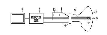
本発明の第1実施形態に係る観察装置1は、図1Aに示すように、被挿入体2の内部に挿入される挿入部31と被挿入体2を撮像する撮像部32とを備える挿入具3と、挿入部31の変位量情報を検出する検出部としての挿入・回転検出部4と、該挿入・回転検出部4からの変位量情報から挿入部31の挿入状態情報を取得し、該挿入状態情報と被挿入体2の形状情報とに基づいて、被挿入体2に対する挿入部31の位置関係を演算して、その演算結果を表示情報として出力する本発明の第1実施形態に係る観察支援装置5と、表示情報を表示する表示装置6と、から構成される。
本発明の第1実施形態に係る観察装置1は、図1Aに示すように、被挿入体2の内部に挿入される挿入部31と被挿入体2を撮像する撮像部32とを備える挿入具3と、挿入部31の変位量情報を検出する検出部としての挿入・回転検出部4と、該挿入・回転検出部4からの変位量情報から挿入部31の挿入状態情報を取得し、該挿入状態情報と被挿入体2の形状情報とに基づいて、被挿入体2に対する挿入部31の位置関係を演算して、その演算結果を表示情報として出力する本発明の第1実施形態に係る観察支援装置5と、表示情報を表示する表示装置6と、から構成される。
挿入具3は、例えば、図2Aに示すような硬性内視鏡装置であり、挿入部31と、該挿入部31と一体的に構成された操作部33と、を備えている。挿入部31は、硬性の管状部材であり、被挿入体2の挿入口21から被挿入体2の内部に挿入可能となっている。なお、被挿入体2の内部は、空気、生理食塩水、あるいは薬液などの所定材料で満たされている。挿入部31の挿入方向の端部(以下、挿入部先端と称する。)には、図2Bに示すように、撮像開口部34が設けられており、また、挿入部31内部の挿入部先端近傍には、図1Aに示すように、撮像部32が内蔵されている。撮像開口部34に入射した光は、撮像部32が受光し撮像を行う。撮像部32が撮像した画像は、本第1実施形態に係る観察支援装置5を通して表示装置6に出力される。
なお、撮像部32は、挿入部31内部の挿入部先端近傍ではなく、操作部33内に配置し、撮像開口部34との間をライトガイド等により結んで、撮像開口部34に入射した光を撮像部32へ導光して撮像を行うようにしても良いことは勿論である。
また、特に図示はしないが、挿入部31内部には、照明用の光ファイバを有しており、操作部33内に配された不図示の照明用光源からの光を導光し、挿入部先端の光供給部35から撮像の為の照明光として出射する。さらに、挿入部先端には、処置用開口部36が設けられ、操作部33から挿入部31内を挿通された処置具が該処置用開口部36から挿入部31外に延出可能とされている。
以下、各部の構成を詳細に説明する。
また、挿入・回転検出部4は、被挿入体2の挿入口21の近傍に設置され、挿入部31の挿入量と回転量を検出して、挿入部31の変位量情報の一つとして、観察支援装置5に出力する。具体的には、この挿入・回転検出部4は、図3Aに示すように、光源41、投光レンズ42、受光レンズ43、光学パターン検出部44、及び変位量算出部45から構成される。
また、挿入・回転検出部4は、被挿入体2の挿入口21の近傍に設置され、挿入部31の挿入量と回転量を検出して、挿入部31の変位量情報の一つとして、観察支援装置5に出力する。具体的には、この挿入・回転検出部4は、図3Aに示すように、光源41、投光レンズ42、受光レンズ43、光学パターン検出部44、及び変位量算出部45から構成される。
光源41から出射した光は、投光レンズ42を通して挿入部31に照射され、該挿入部31で反射した光が受光レンズ43を通して光学パターン検出部44に受光される。光学パターン検出部44は、光学パターンである挿入部31面の画像を検出時間t0,t1,t2,…,tn,…と連続して検出する。
変位量算出部45は、図3Bに示すように、光学パターン検出部44で任意の時間tnに撮像された画像データの画像(光学パターンPTn)内に存在する任意に選択された基準パターンαと、この時間tnから任意の時間経過後の時間tn+1に撮像された画像データの画像(光学パターンPTn+1)内の一部に存在する上記基準パターンαと一致する光学パターンα’と、の画像データ上の変位を比較し、x軸方向及びy軸方向の各々の画像上の変位量を算出する。ここで、図3Bに示すように、光学パターン検出部44のx軸は挿入部31の軸方向に一致するように、光学パターン検出部44は位置決めされている。よって、変位量算出部45で算出されるx軸方向の変位量Δxfは挿入部31の挿入量と比例し、y軸方向の変位量Δyfは挿入部31の回転量と比例する。こうして変位量算出部45で算出された画像上の変位量(挿入量と回転量)は、変位量情報として観察支援装置5に出力される。なお、各々の変位量の増減方向が挿入部31の挿入及び回転の方向を示すため、変位量情報は挿入方向及び回転方向の情報も含むこととなる。
また、本実施形態に係る観察支援装置5は、図1Bに示すように、挿入状態取得部51、被挿入体形状取得部52、パラメータ取得部53、位置関係演算部54、出力部55、及び記憶部56から構成される。
挿入状態取得部51は、上記挿入・回転検出部4の変位量算出部45から出力された変位量情報に基づいて、挿入部31の少なくとも一部の、被挿入体2内部への挿入状態情報、例えば、挿入部31のある点の位置及び向きを取得する。
被挿入体形状取得部52は、被挿入体2の形状情報(被挿入体形状情報)を取得する。この被挿入体形状情報は、挿入部31を被挿入体2に挿入する前に、被挿入体2の外側又は内側からのデータを基に構成されている。
即ち、外部からのデータに基づく被挿入体形状情報は、例えば、CT診断装置や超音波診断装置、及びX線装置などの被挿入体2内を透過して検出することのできる装置を利用して構成される。
また、内部からのデータに基づく被挿入体形状情報は、挿入部31を被挿入体2の空間で動かしたときの軌跡データを利用したり、挿入部先端が被挿入体2に接触したときの位置情報を繋げることにより構成したりする。挿入部先端と被挿入体2との接触時の位置情報を利用すると、空間の大きさを検出することも可能となり、より正確な被挿入体形状情報を取得することが可能である。また、被挿入体2が人体の臓器である場合は体格から推定することで構成したり、被挿入体2が構造物である場合は図面によって形状を入力することで構成したりすることもできる。
なお、被挿入体形状取得部52による被挿入体形状情報の取得は、例えばCT診断装置等の被挿入体形状情報を構成する装置を接続して当該装置より直接取得するものであっても良いし、当該装置から出力された被挿入体形状情報を記憶媒体に一旦保存し、その保存された被挿入体形状情報を読み出して或いはネットワークを介してダウンロードして取得するというものであっても構わない。さらには、被挿入体形状取得部52は、そのようなインタフェースやデータリーダに限らず、それ自体が被挿入体形状情報を構成する機器であっても構わない。
パラメータ取得部53は、例えば、撮像部32の画角情報(レンズの焦点距離など)や、挿入部先端と被挿入体2との間に介在している空気・薬液などの所定材料の屈折率などの、位置関係演算部54での演算に利用されるパラメータを取得するものである。該パラメータ取得部53は、そのようなパラメータを外部から入力して取得しても良いし、予め記憶していても構わない。
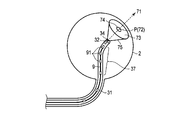
位置関係演算部54は、予め記憶してある挿入部31の既知の形状情報と、上記挿入状態取得部51で取得した挿入状態情報と、上記被挿入体形状取得部52で取得した被挿入体形状情報と、上記パラメータ取得部53が取得したパラメータと、上記撮像部32が撮像した画像(撮像画像)と、に基づいて、被挿入体2に対する挿入部31の位置関係、即ち、挿入部31の全体や先端が被挿入体2内部のどこの部分を向いているのかを演算する。具体的には、位置関係演算部54は、まず、挿入部31の形状情報と挿入状態情報とに基づいて、挿入部先端の位置を演算し、上記挿入・回転検出部4と同様に撮像画像中の光学パターンの移動から挿入部先端の移動量及び移動方向、つまり挿入部先端の向いている方向(軸方向)を演算する。この演算の際、パラメータ取得部53が取得したパラメータにより、補正を加える。そして、それらの演算結果と被挿入体形状情報とに基づいて、挿入部先端が向いている方向と被挿入体2との交点を演算する。即ち、位置関係演算部58は、図4に示すように、挿入部先端が向いている方向(撮像方向71)からなる直線と、被挿入体2の形状との交点72、すなわち視野(撮像領域73)中心を、撮像位置Pとして求める。
通常、観察対象の注目箇所は視野中心に捉えるので、視野の周辺よりも中心が重要であることが多い。なお、ここでは撮像位置Pとして交点を求める例を示したが、被挿入体形状情報に基づいて、挿入部先端の位置と被挿入体2の撮像面との距離から、撮像部32が撮像している被挿入体2の領域である視野(撮像領域73)を、撮像位置Pとして演算するようにしても良い。この場合、挿入部31と被挿入体2との間に介在する所定材料の屈折率、撮像部32の画角情報(レンズの焦点距離など)、等のパラメータを用いることで、より正確に撮像領域73を求めることができる。このように撮像位置Pとして撮像領域73を求めることにより、撮像部32が撮像した範囲を把握することができる。また、視野(撮像領域73)中の一部の領域74または点を撮像位置Pとして演算するようにしても良い。例えば、撮像領域73を正確に検出できない場合に、誤差を考慮して小さい領域を演算することで、撮像されていない範囲を撮像されたと誤検出されることを防ぐことができる。即ち、観察漏れを防ぐことができる。
位置関係演算部54は、こうして求められた撮像位置Pを示す撮像位置情報を出力部55及び記憶部56に出力する。
出力部55は、上記位置関係演算部54の演算結果、即ち上記撮像位置P(例えば交点72)を示す撮像位置情報を、挿入部先端が被挿入体2内部のどこの部分を向いているのか操作者が判断できるような形態で表示装置6に表示するための表示情報を作成し、それを表示装置6に出力する。
記憶部56は、上記位置関係演算部54の演算結果の少なくとも一部、及び、必要により撮像画像を保存する。
以上のような構成の観察支援装置5の動作を、図5を参照して説明する。
まず、被挿入体形状取得部52により、被挿入体形状情報を取得する(ステップS1)。その後、挿入状態取得部51によって、挿入部31の被挿入体2内部への挿入状態情報を取得する(ステップS2)。そして、位置関係演算部54によって、パラメータ取得部53からのパラメータと、撮像部32からの撮像画像とを取得して(ステップS3)、それら被挿入体形状情報、挿入状態情報、パラメータ及び撮像画像に基づいて、被挿入体2に対する挿入部31の位置関係を演算する(ステップS4)。その後、その演算結果を、記憶部56に記憶すると共に、出力部55により出力する(ステップS5)。そして、上記ステップS2に戻って、上記ステップS2乃至ステップS5の動作を繰り返す。
まず、被挿入体形状取得部52により、被挿入体形状情報を取得する(ステップS1)。その後、挿入状態取得部51によって、挿入部31の被挿入体2内部への挿入状態情報を取得する(ステップS2)。そして、位置関係演算部54によって、パラメータ取得部53からのパラメータと、撮像部32からの撮像画像とを取得して(ステップS3)、それら被挿入体形状情報、挿入状態情報、パラメータ及び撮像画像に基づいて、被挿入体2に対する挿入部31の位置関係を演算する(ステップS4)。その後、その演算結果を、記憶部56に記憶すると共に、出力部55により出力する(ステップS5)。そして、上記ステップS2に戻って、上記ステップS2乃至ステップS5の動作を繰り返す。
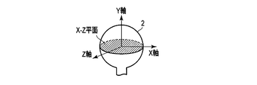
このような動作により、観察支援装置5に接続された表示装置6には、図1Cに示すような表示がなされる。即ち、本実施形態では、出力部55は、撮像部32からの撮像画像(撮像画像表示61)と、被挿入体形状情報としての被挿入体2を所定の箇所で割った2次元図62,63とを、表示装置6に表示するような表示情報を作成して出力する。そしてさらに、この被挿入体2を所定の箇所で割った2次元図62,63上に、撮像位置Pつまり被挿入体2と挿入部先端の軸方向(撮像方向71)との交点72に関わる情報を表示するような表示情報を作成する。ここで、第1の2次元図62は、図6Aに示すように、被挿入体2の形状を被挿入体2の座標においてY-Z平面で割って左右に開いた状態を示す図であり、第2の2次元図63は、第1の2次元図62とは異なる視点の図として、図6Bに示すように、被挿入体2の形状を被挿入体2の座標においてX-Z平面で割って上下に開いた状態を示す図である。そして、出力部55は、これらの2次元図62,63上に、撮像位置Pに関わる情報として、現在位置表示64が表示されるような表示情報を作成する。
なお、この現在位置表示64は、被挿入体2と挿入部先端の軸方向との交点72そのものであっても良いが、上述したように、撮像領域73とする、或いは、例えば交点72を中心として撮像領域中の一部の領域74とするように、ある程度の範囲を有するものとした方が、視認し易い。
また、出力部55は、現在の撮像位置Pに関わる情報としての現在位置表示64に加えて、挿入部31の形状を示す挿入部形状概略表示65が表示されるような表示情報とすることができる。即ち、挿入部先端の位置は上述したように位置関係演算部54によって演算され、挿入部31の形状情報は既知であるので、挿入部31が被挿入体2にどのような挿入状態となっているのかを知ることができ、挿入部形状概略表示65を行うことができる。
またさらに、出力部55は、記憶部56に記憶されている演算結果を使用して、位置軌跡表示66が表示されるような表示情報とすることもできる。この位置軌跡表示66に関しても、現在位置表示64と同様、ある程度の範囲を持ったものとする。またこの場合、現在位置表示64と位置軌跡表示66とを区別可能とするために、互いの色や濃度、模様を変えたり、位置軌跡表示66は点滅表示とする等、何らかの識別表示するような表示情報とすることが望ましい。この識別表示の有無や識別表示の形態は、操作者が選択できるようにしても良い。
また、既に観察した箇所、或いは今後又は再度観察が必要な箇所などに、操作者がマーキング67できる機能を追加しても良い。例えば、操作部12の所定ボタン操作に応じて、当該箇所の情報を記憶部56に記憶すると共に、出力部55がその箇所にマーキング67を表示させるように表示情報を変更する。このマーキング67の箇所は、交点72、撮像領域73、撮像領域中の一部の領域74のうち何れかに固定されていても良いし、操作者が任意に設定できるようにしても良い。このようなマーキング67を可能とすることで、被挿入体2についての観察済み箇所や再観察が必要な箇所、あるいは何らかの処置(除去、採取、補修、など)が必要な箇所、などを確認することが可能となる。さらには、異なる機会に当該被挿入体2の再観察を行う際に前回の要再観察箇所を特定したり、素早く当該箇所に挿入部先端を到達させる場合に利用することが可能となる。また、記憶について、マーキング67した箇所の情報のみでなく、挿入部31の挿入方向などを共に記憶していけば、観察後に確認する場合や、次回同じ状態で観察する場合などに活用することができる。なお、観察済み箇所、要再観察箇所、要処置箇所それぞれが何れの箇所であるのかを特定するための情報も共に設定記憶できるようにしておけば、表示の形態もそれに応じて色や形を変更して、それぞれのマーキング67の意味を操作者が容易に判断できるようになる。
また、このマーキング67に関しては、観察支援装置5にポインティングデバイスや視認認識デバイスを接続し、操作者が表示装置6に表示された撮像画像表示61あるいは2次元図62,63上の任意の範囲または点を指定できるようにしても良い。
また、図1Cに示す2次元図62,63では、領域分割表示68を行っている。これは、学会の通説や規定、標準的に利用されている領域、または予め決めておいた分割方法で2つ以上の領域分割をしているものである。このようにしておくと、被挿入体2のどこの部分であるのかを操作者が判断することが容易となる。
なお、挿入・回転検出部4は、上述のように光学的に被挿入体2に対する挿入部31の形状及び撮像開口部34の位置と向きを検出するものとしたが、その他の方法で検出しても良い。例えば、挿入部31の内部の少なくとも撮像開口部34の近傍にコイルを設け、コイルに電流を流して磁界を発生させ、この磁界を外部で受信する、または、外部で発生させた磁界分布をコイルで受信することにより、コイルすなわち撮像開口部34の位置や向きを検出できる。
以上のように、本実施形態によれば、挿入状態取得部51によって、被挿入体2内部に挿入される挿入部31の(少なくとも一部の、)(被挿入体2内部への)挿入状態情報(例えば、挿入部31のある点(挿入部先端)の位置・向き)を取得し、被挿入体形状取得部52によって、被挿入体2の形状情報を取得し、それら挿入状態情報と被挿入体形状情報を位置関係演算部54に入力して、被挿入体2に対する挿入部31の位置関係(挿入部31全体や挿入部先端の位置や向き)を演算し、出力部55によって、その位置関係演算部54の演算結果を表示情報として出力するようにしているので、被挿入体内のどこを撮像しているのかを判断するための情報を提供できる。すなわち、目で直接見ることのできない被挿入体内部に挿入部31を有する挿入具3で観察する際、表示装置6が表示している撮像画像が被挿入体2のどの当たりの場所で、どの方向から観察しているかを理解することができる。また、被挿入体2内の観察済み箇所、または未観察箇所を容易に識別することが可能となり、見落としを防止することが可能となる。
また、位置関係演算部54は、挿入部先端の位置と、被挿入体2の撮像面との距離から被挿入体2に対する挿入部31の位置関係を求め、出力部55は、この位置関係を表示情報として出力するので、表示装置6に被挿入体2の観察範囲(被挿入体2に対する挿入部31の位置関係)を表示することができる。このため、挿入部先端で被挿入体2内を観察していく際、次に観察すべき箇所に素早く動かしていくことができる。また、見落とし無く挿入部31を動かしていくことができる。
また、被挿入体2と挿入部31との間に生理食塩水や薬液などの所定材料があった場合に、屈折率差により光の屈折が発生し、撮像部32による被挿入体2の観察範囲(被挿入体2に対する挿入部31の位置関係)が異なるが、位置関係演算部54は、さらに、挿入部31と被挿入体2との間に介在する所定材料の屈折率をパラメータ取得部53から入力して被挿入体2に対する挿入部31の位置関係を求めるようにしているので、より正確な観察範囲を得ることが可能となる。
さらに、撮像部32の撮像範囲75(図4参照)は、撮像部32の画角情報(レンズの焦点距離など)によっても変わるため、位置関係演算部54は、撮像部32の画角情報をパラメータ取得部53から入力して被挿入体2に対する挿入部31の位置関係を求めるようにしているので、より正確な観察範囲を得ることが可能となる。
また、位置関係演算部54の演算結果の少なくとも一部を保存する記憶部56をさらに有し、該記憶部56に、表示装置6に表示した被挿入体2の観察範囲(被挿入体2に対する挿入部31の位置関係)を記憶していくことにより、被挿入体2の内壁に対して挿入部先端で観察した箇所と未観察の箇所とを識別していくことが可能となる。例えば、表示装置6に現在位置表示64として表示している観察範囲を、別の箇所に移動していく際に消去することなく位置軌跡表示66として残していけば、該位置軌跡表示66によって、観察済みの箇所と未観察箇所とを容易に判断することが可能である。この構成により、見落とし無く被挿入体2全体を観察することが可能となる。
また、出力部55は、位置関係演算部54の結果として、2つ以上の異なる所定状態を区別可能な方法で表示する、例えば区別可能なマーキングを表示する表示情報を出力するようにしているので、複数の状態(現在の観察範囲、癌、炎症、欠損、傷、腐食など)を見た目で区別することが可能となる。この複数の状態を記憶しておけば、異なる時間に再度同じ場所を観察したいときに所定の状態にある箇所のみを観察することができ、観察効率を向上させることが可能となる。
なお、所定状態の場合分けは、挿入部31の操作者が選択可能とすることができる。この場合、操作者の意思に基づいて場合分けすることができるため、再観察の基準などを操作者や操作者の属する分野基準で任意に設定することが可能となる。つまり、医療分野や工業分野など、それぞれの分野に応じた使い分けをすることが可能となる。
また、記憶部56は、撮像画像を、位置関係演算部54の演算結果と関連付けて記憶しておくようにすることで、所定箇所の状態について、記憶したときの観察状態と、現在の観察状態とを比較して、その違い・変化を得ることが可能となる。
また、出力部55は、複数の領域に領域分割表示がされている表示情報を出力するようにしている。このように、表示画面に学会の通説や規定、または標準的に利用されている領域が判るように領域分割表示されていると、観察範囲を表示している際に、どこの部分を観察しているかを理解し易くすることが可能となる。
なお、出力部55は、同一の領域を異なる領域分割表示とする表示情報を出力することで、3次元で表される被挿入体2を2次元で表現した場合、奥行き方向に当たる部分は、見えなくなったり、見え難くなったりするが、これを防ぐことが可能となる。従って、見落とし箇所やマーキング位置を確実に認識することが可能となる。
撮像位置を表示する例を記載したが、これに加えて、挿入部先端の位置、向き、さらには、挿入部先端の位置、向きの履歴を表示しても良い。このことを、図7A乃至図7Cと図8A及び図8Bを参照して説明する。図7A乃至図7Cは、分岐のある被挿入体2に挿入部31を挿入した際の、表示装置6に表示される内容を示している。
位置関係演算部54は、挿入部先端の位置、向きを演算し、出力部55及び記憶部56に出力する。なお、挿入部先端の位置、向きの演算は上記演算と同様のため、ここでは説明を省略する。
図7Aは、被挿入体の形状を示す2次元図62A上に、挿入部31の現時点での形状を示す挿入部形状概略表示65と、挿入部31の先端位置(である撮像開口部34の位置)の現在の位置を表わす現在位置表示64Aと、撮像開口部34の位置の軌跡である位置軌跡表示66Aと、を示したものである。なお、撮像位置の軌跡である位置軌跡表示66は省略している。先端位置の軌跡表示により、先端位置(である撮像開口部34の位置)が被挿入体2のどの位置を通過し、現時点でどの位置にあるかがわかる様になる。
先端位置(である撮像開口部34の位置)が分かることで、撮像対象のどの部分まで到達しているかが分かる。現在位置が正確に分かることで、この情報を用いて、現在位置に応じてすべき観察・処置や、現在位置から狙いの位置への経路の検討を、この場所であったらという推定無しに、行うことができる。そのため、狙いの位置へ行くのに試行錯誤を繰り返したり、狙いの位置に到達したか、観察画像を見るなど様々な方法で確認したりする必要が無くなる。その結果、現在位置から狙いの位置まで最短コースに近い経路を取って1回で到達できる可能性が上がり、時間短縮出来ると共に、位置に関する状況把握が出来ていることにより、落ち着いた、自信を持った操作につながる。
図7Aに示した、先端位置(である撮像開口部34の位置)の履歴としての軌跡に加え、挿入部先端(である撮像開口部34)が向いている方向を表示しても良い。図7Bでは、挿入部先端の向きである、撮像開口部34が向いている方向を矢印69で示している。撮像開口部34の現在の位置と向きだけでなく、撮像開口部34の軌跡上の幾つかの位置で方向の情報を矢印69で加えている。先端位置の軌跡と向きの表示により、挿入部先端の撮像開口部34の位置情報である、先端位置の軌跡と、どの方向を向きながら位置が変化したかがわかる様になる。
なお、撮像のための光学系にもよるが、本例では、挿入部先端にある撮像開口部34が向いている方向が視野中心であり、撮像画像の中央である。
先端位置と向きが分かることで、撮像対象での到達位置と向きが分かる。現在位置と向きから、観察視野方向や視野中心が分かる。到達位置と向きや観察視野方向や視野中心が正確に分かることで、この情報を用いて、現在位置と向きに応じてすべき観察・処置や、現在位置から狙いの位置への経路、および、移動する際の挿入部31の形状や操作方法の検討を、現在位置と向きがこうであったらという推定無しに、行うことができる。特に挿入部先端の向きが分かっていることで、狙いの位置や向きに到達するための挿抜や湾曲などの操作方法・手順が検討できるようになる。
挿入部先端の向き、即ち、撮像開口部34が向いている方向は、挿入部先端の姿勢、または、回転を含めて表すものとして三次元的に示しても良い。
挿入部先端に固定された座標系、即ち、挿入部先端の位置や姿勢が変化しない座標系の回転を挿入部先端の「三次元の方向」と定義した時、挿入部先端の三次元の方向の軌跡を図7Cに示す。図7Cでは、三次元の方向(姿勢)を示すために、挿入部先端の向き、即ち、撮像開口部34の向いている方向を三方向(x方向、y方向、z方向)の矢印69Aで示している。
また、回転を含めた三次元方向に関する情報を、撮像部32が撮像した画像と共に表示するようにしても良い。
このように、挿入部先端の位置と三次元の方向が分かることで、例えば、挿入部先端の撮像位置での回転を含めた撮像方向がわかる様になる。また、撮像以外に治療などでも先端向き周りの回転の影響を考慮することができるようになる。
撮像位置での回転を含めた撮像方向については、例えば、図8A及び図8Bに示すように、撮像開口部34が向いている方向が同じ場合でも、挿入部31が撮像方向周りに回転すると撮像対象81に対する撮像開口部34も回転する。図8Aと図8Bとでは180°回転しているため、上下が逆になっており、このような場合、撮像部32が撮像した撮像画像Iも上下が逆に表示される。こうした観察や治療時の撮像方向周りの回転の影響も考慮することが可能となり、撮像画像での天地を誤ったりせず、正確に把握することができるようになる。
[第2実施形態]
次に、本発明の第2実施形態を説明する。
次に、本発明の第2実施形態を説明する。
本第2実施形態は、挿入具3が、図9に示すような軟性内視鏡装置の場合の例である。このような軟性内視鏡装置は、挿入部31が可撓性の管状部材である点が、上記第1実施形態で説明したような硬性内視鏡装置とは異なっている。そして、この挿入部31は、図10に示すように、挿入部先端近傍に、湾曲部37を有しており、該湾曲部37は、特に図示はしていないが、操作部33に設けられた操作レバーにワイヤによって繋がっている。これにより、操作レバーを動かすことでワイヤが引かれ、湾曲部37の湾曲操作が可能となっている。
このような軟性内視鏡装置では、上記第1実施形態で説明したような硬性内視鏡装置のように挿入部31の形状は固定されておらず、被挿入体2の内部形状、操作者の湾曲操作に応じて、挿入部31の形状が変化する。
そのため、本第2実施形態に係る観察装置1では、図11に示すように、挿入部31内部に、ファイバ形状センサ9が設置されている。このファイバ形状センサ9は、複数の光ファイバから構成され、1本の光ファイバに一箇所の湾曲検出部91を有している。この湾曲検出部91は、光ファイバのクラッドが除去されコアが露出されており、光吸収部材が塗布されて構成されている。このような湾曲検出部91では、図12A乃至図12Cに示すように、湾曲部37の湾曲に応じて該湾曲検出部91で吸収される光の量が変化するため、光ファイバ92内を導光する光の量が変化する、即ち光伝達量が変化する。
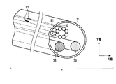
このような構成のファイバ形状センサ9は、図13に示すX軸方向の湾曲と、Y軸方向の湾曲を検出するために、それぞれX軸方向、Y軸方向に向いている2つの湾曲検出部91が対となるように2本の光ファイバ92が配置され、一箇所の湾曲量を検出する。そして、対となっている湾曲検出部91が挿入部31の長手方向(挿入方向)に並んで配置されるように、複数の光ファイバ92が配置されている。そして、不図示の光源からの光を各光ファイバ92で導光し、各光ファイバ92の湾曲量によって変化する光伝達量を不図示の受光部で検出する。こうして検出された光伝達量は、挿入部31の変位量情報の一つとして、観察支援装置5に出力される。
なお、湾曲検出部91は、挿入部31の湾曲部37にだけでなく、それよりも操作部側にも設けることで、挿入部31の可撓性により被挿入体2の内部構造に応じて自由に湾曲した挿入部31の湾曲部37以外の部分の湾曲状態も検出できるようにしておくことが望ましい。
なお、図13に示すように、挿入部31内部には、照明用光ファイバ38と撮像部用配線39も設けられている。照明用光ファイバ38によって、操作部33内に配された不図示の照明用光源からの光を導光し、挿入部先端から照明光として出射することで、撮像部32は、暗部である被挿入体2の内部を撮像することができる。
また、本実施形態に係る観察支援装置5は、図14に示すように、上記第1実施形態の構成に加えて、形状演算部57を有する。本実施形態における挿入状態取得部51は、上記ファイバ形状センサ9が検出した変位量情報としての各光ファイバ92の湾曲量によって変化する光伝達量に基づいて、被挿入体2内部への挿入状態情報として、さらに、挿入部31の各湾曲検出部91の位置及び向きを取得する。形状演算部57は、この挿入状態情報としての位置及び向きに基づいて挿入部31の形状を演算する。また、本実施形態における位置関係演算部54は、この形状演算部57が求めた挿入部31の形状情報と、上記挿入状態取得部51で取得した挿入状態情報と、上記被挿入体形状取得部52で取得した被挿入体形状情報と、上記パラメータ取得部53が取得したパラメータと、に基づいて、被挿入体2に対する挿入部31の位置関係、即ち、撮像位置Pを求める。なお、挿入部先端の移動量及び移動方向、つまり挿入部先端の向いている方向(軸方向)は、挿入部31の形状情報と被挿入体形状情報とから求めることができるので、撮像位置Pを演算する際に、本実施形態では、撮像画像を用いる必要はない。
以上のような構成の観察支援装置5の動作を、図15を参照して説明する。
まず、被挿入体形状取得部52により、被挿入体形状情報を取得する(ステップS1)。その後、挿入状態取得部51によって、挿入部31の被挿入体2内部への挿入状態情報を取得する(ステップS2)。そして、形状演算部57によって、挿入状態取得部51が取得した挿入状態情報に基づいて挿入部31の形状を演算する(ステップS6)。その後、位置関係演算部54によって、パラメータ取得部53からのパラメータを取得して(ステップS7)、それら被挿入体形状情報、挿入状態情報、挿入部31の形状情報及びパラメータに基づいて、被挿入体2に対する挿入部31の位置関係を演算する(ステップS4)。そして、その演算結果を、記憶部56に記憶すると共に、出力部55により出力した後(ステップS5)、上記ステップS2に戻って、上記ステップS2,S6,S7,S4,S5の動作を繰り返す。
まず、被挿入体形状取得部52により、被挿入体形状情報を取得する(ステップS1)。その後、挿入状態取得部51によって、挿入部31の被挿入体2内部への挿入状態情報を取得する(ステップS2)。そして、形状演算部57によって、挿入状態取得部51が取得した挿入状態情報に基づいて挿入部31の形状を演算する(ステップS6)。その後、位置関係演算部54によって、パラメータ取得部53からのパラメータを取得して(ステップS7)、それら被挿入体形状情報、挿入状態情報、挿入部31の形状情報及びパラメータに基づいて、被挿入体2に対する挿入部31の位置関係を演算する(ステップS4)。そして、その演算結果を、記憶部56に記憶すると共に、出力部55により出力した後(ステップS5)、上記ステップS2に戻って、上記ステップS2,S6,S7,S4,S5の動作を繰り返す。
このような動作により、観察支援装置5に接続された表示装置6には、図16に示すような表示がなされる。なお、本実施形態では、挿入部31の形状を示す挿入部形状概略表示65は、形状演算部57が求めた挿入部31の形状に対応したものとなる。
従って、挿入部31の形状が既知でない場合にも、挿入部31の形状を演算することで、上記第1実施形態と同様に動作して、同様の効果が得られる。
以上、実施形態に基づいて本発明を説明したが、本発明は、上述した実施形態に限定されるものではなく、本発明の要旨の範囲内で種々の変形や応用が可能なことは勿論である。
例えば、図5或いは図15のフローチャートに示した機能を実現するソフトウェアのプログラムをコンピュータに供給し、当該コンピュータがこのプログラムを実行することによって、上記機能を実現することも可能である。
また、出力部55が出力する表示情報つまり表示装置6への表示形態も、2次元図62,63のような表示に限定するものではない。例えば、図17のように3次元図90で表示するようなものでも良い。
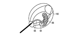
さらに、図18に示すように、挿入部形状概略表示65上に、湾曲検出部100の位置を示す湾曲検出部表示65Aを重畳して表示することも可能である。
Claims (19)
- 被挿入体内部に挿入される挿入部と、
前記挿入部に配置され、前記被挿入体を撮像する撮像部と、
前記挿入部の挿入状態情報を取得する挿入状態取得部と、
前記被挿入体の形状情報を取得する被挿入体形状取得部と、
前記挿入状態情報と前記被挿入体形状情報とを入力し、前記被挿入体に対する前記挿入部の位置関係を演算する位置関係演算部と、
前記位置関係演算部の演算結果を表示情報として出力する出力部と、
を有することを特徴とする観察装置。 - 前記位置関係演算部は、前記被挿入体に対する前記挿入部の先端の位置関係を演算することを特徴とする請求項1に記載の観察装置。
- 前記位置関係演算部は、前記挿入部先端の位置関係と、前記被挿入体の形状情報を用いて前記撮像部の撮像位置を求め、
前記出力部は、前記撮像位置を前記表示情報として出力することを特徴とする請求項2に記載の観察装置。 - 前記位置関係演算部の演算結果の少なくとも一部を保存する記憶部をさらに有することを特徴とする請求項1乃至3の何れかに記載の観察装置。
- 前記挿入部の挿入状態を検出する検出部をさらに有し、
前記検出部は、
前記挿入部の内部に搭載され、前記挿入部の形状を検出する形状センサと、
前記被挿入体への前記挿入部の挿入口に設けられ、前記挿入部が通過するときの挿入量及び回転量を検出する挿入部センサと、
の少なくとも一方を含む、ことを特徴とする請求項1乃至4の何れかに記載の観察装置。 - 前記挿入状態情報に基づいて、前記挿入部の形状を演算する形状演算部をさらに有し、
前記出力部は、前記形状演算部の演算結果を前記表示情報として出力することを特徴とする請求項1乃至5の何れかに記載の観察装置。 - 前記位置関係演算部は、さらに前記挿入部と前記被挿入体との間に介在する所定材料の屈折率を入力して前記被挿入体に対する前記挿入部の位置関係を求めることを特徴とする請求項2に記載の観察装置。
- 前記位置関係演算部は、さらに前記撮像部の画角情報を入力して前記被挿入体に対する前記挿入部の位置関係を求めることを特徴とする請求項2に記載の観察装置。
- 前記出力部は、前記位置関係演算部の結果として、2つ以上の異なる所定状態を区別可能な方法で表示する表示情報を出力することを特徴とする請求項1乃至8の何れかに記載の観察装置。
- 前記記憶部は、前記撮像部の撮像画像を、前記位置関係演算部の演算結果と関連付けて記憶しておくことを特徴とする請求項4に記載の観察装置。
- 前記出力部は、複数の領域に領域分割表示がされている表示情報を出力することを特徴とする請求項1に記載の観察装置。
- 前記出力部は、同一の領域を異なる領域分割表示とする表示情報を出力することを特徴とする請求項1に記載の観察装置。
- 前記出力部から出力された前記表示情報を表示する表示装置をさらに有することを特徴とする請求項1に記載の観察装置。
- 前記出力部は、前記表示情報に、前記位置関係演算部の現在の演算結果よりも前の演算結果を前記表示装置に軌跡表示として表示させる情報を含めることを特徴とする請求項13に記載の観察装置。
- 前記位置関係演算部は、前記被挿入体に対する前記挿入部先端の方向をさらに求め、
前記出力部は、前記挿入部の先端の方向を前記表示情報として出力することを特徴とする請求項2に記載の観察装置。 - 前記位置関係演算部は、前記挿入部先端の、前記被挿入体に対する前記挿入部先端の方向周りの回転量をさらに求め、
前記出力部は、前記挿入部先端の方向周りの回転量を前記表示情報として出力することを特徴とする請求項2に記載の観察装置。 - 被挿入体に挿入部を挿入することで前記被挿入体内部を撮像する観察装置に用いられる観察支援装置において、
前記挿入部の挿入状態情報を取得する挿入状態取得部と、
前記被挿入体の形状情報を取得する被挿入体形状取得部と、
前記挿入状態情報と前記被挿入体形状情報とを入力し、前記被挿入体に対する前記挿入部の位置関係を演算する位置関係演算部と、
前記位置関係演算部の演算結果を表示情報として出力する出力部と、
を有することを特徴とする観察支援装置。 - 被挿入体に挿入部を挿入することで前記被挿入体内部を撮像する観察装置に用いられる観察方法において、
前記挿入部の挿入状態情報を取得する挿入状態取得ステップと、
前記被挿入体の形状情報を取得する被挿入体形状取得ステップと、
前記挿入状態情報と前記被挿入体形状情報とを入力し、前記被挿入体に対する前記挿入部の位置関係を演算する位置関係演算ステップと、
前記位置関係演算ステップの演算結果を表示情報として出力する出力ステップと、
を有することを特徴とする観察支援方法。 - コンピュータに、
被挿入体に挿入部を挿入することで前記被挿入体内部を撮像する観察装置における前記挿入部の挿入状態情報を取得する挿入状態取得手順と、
前記被挿入体の形状情報を取得する被挿入体形状取得手順と、
前記挿入状態情報と前記被挿入体形状情報とを入力し、前記被挿入体に対する前記挿入部の位置関係を演算する位置関係演算手順と、
前記位置関係演算手順の演算結果を表示情報として出力する出力手順と、
を実行させるためのプログラム。
Priority Applications (3)
| Application Number | Priority Date | Filing Date | Title |
|---|---|---|---|
| CN201380054139.8A CN104755005B (zh) | 2012-10-16 | 2013-09-27 | 观察装置以及观察支援装置 |
| EP13847721.1A EP2910174A4 (en) | 2012-10-16 | 2013-09-27 | OBSERVATION DEVICE, DEVICE, AND OBSERVATION SUPPORT METHOD, AND PROGRAM |
| US14/688,327 US20150216391A1 (en) | 2012-10-16 | 2015-04-16 | Observation apparatus, observation supporting device, observation supporting method and recording medium |
Applications Claiming Priority (2)
| Application Number | Priority Date | Filing Date | Title |
|---|---|---|---|
| JP2012-229254 | 2012-10-16 | ||
| JP2012229254A JP6146981B2 (ja) | 2012-10-16 | 2012-10-16 | 観察装置、観察支援装置及びプログラム |
Related Child Applications (1)
| Application Number | Title | Priority Date | Filing Date |
|---|---|---|---|
| US14/688,327 Continuation US20150216391A1 (en) | 2012-10-16 | 2015-04-16 | Observation apparatus, observation supporting device, observation supporting method and recording medium |
Publications (1)
| Publication Number | Publication Date |
|---|---|
| WO2014061428A1 true WO2014061428A1 (ja) | 2014-04-24 |
Family
ID=50488000
Family Applications (1)
| Application Number | Title | Priority Date | Filing Date |
|---|---|---|---|
| PCT/JP2013/076398 Ceased WO2014061428A1 (ja) | 2012-10-16 | 2013-09-27 | 観察装置、観察支援装置、観察支援方法及びプログラム |
Country Status (5)
| Country | Link |
|---|---|
| US (1) | US20150216391A1 (ja) |
| EP (1) | EP2910174A4 (ja) |
| JP (1) | JP6146981B2 (ja) |
| CN (1) | CN104755005B (ja) |
| WO (1) | WO2014061428A1 (ja) |
Cited By (1)
| Publication number | Priority date | Publication date | Assignee | Title |
|---|---|---|---|---|
| US11213189B2 (en) * | 2016-07-14 | 2022-01-04 | Aesculap Ag | Endoscopic device and method for endoscopic examination |
Families Citing this family (9)
| Publication number | Priority date | Publication date | Assignee | Title |
|---|---|---|---|---|
| JP6128796B2 (ja) * | 2012-10-25 | 2017-05-17 | オリンパス株式会社 | 挿入システム、挿入支援装置、挿入支援装置の作動方法及びプログラム |
| US10376181B2 (en) * | 2015-02-17 | 2019-08-13 | Endochoice, Inc. | System for detecting the location of an endoscopic device during a medical procedure |
| JP2018050890A (ja) | 2016-09-28 | 2018-04-05 | 富士フイルム株式会社 | 画像表示装置及び画像表示方法並びにプログラム |
| JP6710284B2 (ja) * | 2016-10-12 | 2020-06-17 | オリンパス株式会社 | 挿入システム |
| WO2018135041A1 (ja) * | 2017-01-17 | 2018-07-26 | オリンパス株式会社 | 内視鏡挿入形状観測装置 |
| CN110740674B (zh) * | 2017-06-12 | 2022-04-01 | 奥林巴斯株式会社 | 插入辅助系统和插入辅助方法 |
| JP7681294B2 (ja) * | 2021-04-14 | 2025-05-22 | i-PRO株式会社 | 内視鏡システム |
| JP7780396B2 (ja) * | 2022-06-27 | 2025-12-04 | 株式会社エビデント | 挿入状態検出システム、挿入状態検出方法、およびプログラム |
| CN115836941A (zh) * | 2022-10-17 | 2023-03-24 | 武汉左点科技有限公司 | 可视耳勺耳内图像定位系统及设备 |
Citations (3)
| Publication number | Priority date | Publication date | Assignee | Title |
|---|---|---|---|---|
| US6846286B2 (en) | 2001-05-22 | 2005-01-25 | Pentax Corporation | Endoscope system |
| JP2007111551A (ja) * | 2006-12-25 | 2007-05-10 | Olympus Corp | 内視鏡形状検出装置 |
| WO2012132638A1 (ja) * | 2011-03-30 | 2012-10-04 | オリンパスメディカルシステムズ株式会社 | 内視鏡システム |
Family Cites Families (13)
| Publication number | Priority date | Publication date | Assignee | Title |
|---|---|---|---|---|
| US6902528B1 (en) * | 1999-04-14 | 2005-06-07 | Stereotaxis, Inc. | Method and apparatus for magnetically controlling endoscopes in body lumens and cavities |
| JP4388549B2 (ja) * | 2004-03-18 | 2009-12-24 | オリンパス株式会社 | 挿入装置 |
| JP4481711B2 (ja) * | 2004-04-09 | 2010-06-16 | オリンパス株式会社 | 挿入形状検出プローブ |
| JP4695420B2 (ja) * | 2004-09-27 | 2011-06-08 | オリンパス株式会社 | 湾曲制御装置 |
| JP4647972B2 (ja) * | 2004-11-15 | 2011-03-09 | オリンパス株式会社 | 内視鏡形状検出装置 |
| JP4766902B2 (ja) * | 2005-03-31 | 2011-09-07 | オリンパスメディカルシステムズ株式会社 | 手術支援装置 |
| JP4914574B2 (ja) * | 2005-04-18 | 2012-04-11 | オリンパスメディカルシステムズ株式会社 | 内視鏡形状検出装置 |
| JP4789545B2 (ja) * | 2005-08-25 | 2011-10-12 | オリンパスメディカルシステムズ株式会社 | 内視鏡挿入形状解析装置 |
| US20070161854A1 (en) * | 2005-10-26 | 2007-07-12 | Moshe Alamaro | System and method for endoscopic measurement and mapping of internal organs, tumors and other objects |
| US9636188B2 (en) * | 2006-03-24 | 2017-05-02 | Stryker Corporation | System and method for 3-D tracking of surgical instrument in relation to patient body |
| US8248414B2 (en) * | 2006-09-18 | 2012-08-21 | Stryker Corporation | Multi-dimensional navigation of endoscopic video |
| JP5208495B2 (ja) * | 2007-12-27 | 2013-06-12 | オリンパスメディカルシステムズ株式会社 | 医療用システム |
| US8337397B2 (en) * | 2009-03-26 | 2012-12-25 | Intuitive Surgical Operations, Inc. | Method and system for providing visual guidance to an operator for steering a tip of an endoscopic device toward one or more landmarks in a patient |
-
2012
- 2012-10-16 JP JP2012229254A patent/JP6146981B2/ja active Active
-
2013
- 2013-09-27 EP EP13847721.1A patent/EP2910174A4/en not_active Withdrawn
- 2013-09-27 WO PCT/JP2013/076398 patent/WO2014061428A1/ja not_active Ceased
- 2013-09-27 CN CN201380054139.8A patent/CN104755005B/zh active Active
-
2015
- 2015-04-16 US US14/688,327 patent/US20150216391A1/en not_active Abandoned
Patent Citations (5)
| Publication number | Priority date | Publication date | Assignee | Title |
|---|---|---|---|---|
| US6846286B2 (en) | 2001-05-22 | 2005-01-25 | Pentax Corporation | Endoscope system |
| JP2007111551A (ja) * | 2006-12-25 | 2007-05-10 | Olympus Corp | 内視鏡形状検出装置 |
| WO2012132638A1 (ja) * | 2011-03-30 | 2012-10-04 | オリンパスメディカルシステムズ株式会社 | 内視鏡システム |
| JP5159995B2 (ja) * | 2011-03-30 | 2013-03-13 | オリンパスメディカルシステムズ株式会社 | 内視鏡システム |
| US20130096423A1 (en) * | 2011-03-30 | 2013-04-18 | Olympus Medical Systems Corp. | Endoscope system |
Non-Patent Citations (1)
| Title |
|---|
| See also references of EP2910174A4 |
Cited By (1)
| Publication number | Priority date | Publication date | Assignee | Title |
|---|---|---|---|---|
| US11213189B2 (en) * | 2016-07-14 | 2022-01-04 | Aesculap Ag | Endoscopic device and method for endoscopic examination |
Also Published As
| Publication number | Publication date |
|---|---|
| CN104755005A (zh) | 2015-07-01 |
| JP2014079376A (ja) | 2014-05-08 |
| CN104755005B (zh) | 2016-09-14 |
| EP2910174A1 (en) | 2015-08-26 |
| JP6146981B2 (ja) | 2017-06-14 |
| EP2910174A4 (en) | 2016-06-29 |
| US20150216391A1 (en) | 2015-08-06 |
Similar Documents
| Publication | Publication Date | Title |
|---|---|---|
| JP6146981B2 (ja) | 観察装置、観察支援装置及びプログラム | |
| JP6128796B2 (ja) | 挿入システム、挿入支援装置、挿入支援装置の作動方法及びプログラム | |
| JP6128792B2 (ja) | 観察装置、観察支援装置、観察装置の作動方法及びプログラム | |
| US20250152257A1 (en) | Device and method for tracking the position of an endoscope within a patient's body | |
| CN104717913B (zh) | 具有插入部及插入部件的插入系统 | |
| CN102740755B (zh) | 医疗设备 | |
| CN107529939B (zh) | 插拔装置、插入部的直接操作推测方法及非暂时性存储插入部的直接操作推测程序的存储介质 | |
| CN105828721B (zh) | 用于微创介入的形状感测的机器人超声 | |
| US10846883B2 (en) | Method for calibrating objects in a reference coordinate system and method for tracking objects | |
| JP6108812B2 (ja) | 挿入装置 | |
| US20140243660A1 (en) | Shape sensing assisted medical procedure | |
| JP2009279249A (ja) | 医療機器 | |
| US20150342697A1 (en) | Surgical Microscope | |
| JP2017225700A (ja) | 観察支援装置及び内視鏡システム | |
| JP2023018984A (ja) | 挿入支援システム、挿入支援方法、およびプログラム |
Legal Events
| Date | Code | Title | Description |
|---|---|---|---|
| 121 | Ep: the epo has been informed by wipo that ep was designated in this application |
Ref document number: 13847721 Country of ref document: EP Kind code of ref document: A1 |
|
| NENP | Non-entry into the national phase |
Ref country code: DE |
|
| WWE | Wipo information: entry into national phase |
Ref document number: 2013847721 Country of ref document: EP |