WO2014064887A1 - 倒立型移動体 - Google Patents
倒立型移動体 Download PDFInfo
- Publication number
- WO2014064887A1 WO2014064887A1 PCT/JP2013/005824 JP2013005824W WO2014064887A1 WO 2014064887 A1 WO2014064887 A1 WO 2014064887A1 JP 2013005824 W JP2013005824 W JP 2013005824W WO 2014064887 A1 WO2014064887 A1 WO 2014064887A1
- Authority
- WO
- WIPO (PCT)
- Prior art keywords
- step cover
- hinge
- base
- inverted
- moving body
- Prior art date
- Legal status (The legal status is an assumption and is not a legal conclusion. Google has not performed a legal analysis and makes no representation as to the accuracy of the status listed.)
- Ceased
Links
Images







Classifications
-
- B—PERFORMING OPERATIONS; TRANSPORTING
- B23—MACHINE TOOLS; METAL-WORKING NOT OTHERWISE PROVIDED FOR
- B23K—SOLDERING OR UNSOLDERING; WELDING; CLADDING OR PLATING BY SOLDERING OR WELDING; CUTTING BY APPLYING HEAT LOCALLY, e.g. FLAME CUTTING; WORKING BY LASER BEAM
- B23K26/00—Working by laser beam, e.g. welding, cutting or boring
- B23K26/352—Working by laser beam, e.g. welding, cutting or boring for surface treatment
- B23K26/3568—Modifying rugosity
-
- B—PERFORMING OPERATIONS; TRANSPORTING
- B62—LAND VEHICLES FOR TRAVELLING OTHERWISE THAN ON RAILS
- B62K—CYCLES; CYCLE FRAMES; CYCLE STEERING DEVICES; RIDER-OPERATED TERMINAL CONTROLS SPECIALLY ADAPTED FOR CYCLES; CYCLE AXLE SUSPENSIONS; CYCLE SIDE-CARS, FORECARS, OR THE LIKE
- B62K11/00—Motorcycles, engine-assisted cycles or motor scooters with one or two wheels
- B62K11/007—Automatic balancing machines with single main ground engaging wheel or coaxial wheels supporting a rider
-
- B—PERFORMING OPERATIONS; TRANSPORTING
- B62—LAND VEHICLES FOR TRAVELLING OTHERWISE THAN ON RAILS
- B62K—CYCLES; CYCLE FRAMES; CYCLE STEERING DEVICES; RIDER-OPERATED TERMINAL CONTROLS SPECIALLY ADAPTED FOR CYCLES; CYCLE AXLE SUSPENSIONS; CYCLE SIDE-CARS, FORECARS, OR THE LIKE
- B62K23/00—Rider-operated controls specially adapted for cycles, i.e. means for initiating control operations, e.g. levers, grips
- B62K23/08—Rider-operated controls specially adapted for cycles, i.e. means for initiating control operations, e.g. levers, grips foot actuated
-
- B—PERFORMING OPERATIONS; TRANSPORTING
- B60—VEHICLES IN GENERAL
- B60L—PROPULSION OF ELECTRICALLY-PROPELLED VEHICLES; SUPPLYING ELECTRIC POWER FOR AUXILIARY EQUIPMENT OF ELECTRICALLY-PROPELLED VEHICLES; ELECTRODYNAMIC BRAKE SYSTEMS FOR VEHICLES IN GENERAL; MAGNETIC SUSPENSION OR LEVITATION FOR VEHICLES; MONITORING OPERATING VARIABLES OF ELECTRICALLY-PROPELLED VEHICLES; ELECTRIC SAFETY DEVICES FOR ELECTRICALLY-PROPELLED VEHICLES
- B60L2200/00—Type of vehicles
- B60L2200/16—Single-axle vehicles
-
- B—PERFORMING OPERATIONS; TRANSPORTING
- B60—VEHICLES IN GENERAL
- B60L—PROPULSION OF ELECTRICALLY-PROPELLED VEHICLES; SUPPLYING ELECTRIC POWER FOR AUXILIARY EQUIPMENT OF ELECTRICALLY-PROPELLED VEHICLES; ELECTRODYNAMIC BRAKE SYSTEMS FOR VEHICLES IN GENERAL; MAGNETIC SUSPENSION OR LEVITATION FOR VEHICLES; MONITORING OPERATING VARIABLES OF ELECTRICALLY-PROPELLED VEHICLES; ELECTRIC SAFETY DEVICES FOR ELECTRICALLY-PROPELLED VEHICLES
- B60L2260/00—Operating Modes
- B60L2260/20—Drive modes; Transition between modes
- B60L2260/34—Stabilising upright position of vehicles, e.g. of single axle vehicles
Definitions
- the present invention relates to an inverted moving body, and more particularly to an inverted moving body that detects the boarding of a passenger and performs inverted control.
- Patent Document 1 discloses a rider detector that detects that a rider is on a transport vehicle. As shown in FIG. 16, in this rider detector, when the rider rides on the base mat 501, the base mat 501 and the base cover 503 below it are elastically deformed with the mat wall 502 of the base mat 501 as a fulcrum. The rider is detected by detecting the interruption of the conduction of the light beam 504.
- the present invention has been made on the basis of the above-described knowledge, and an object thereof is to provide an inverted moving body capable of improving the accuracy of detecting a passenger.
- An inverted mobile body includes a wheel, a base that holds the wheel in a drivable manner, a step cover that is connected to an upper portion of the base and on which a passenger rides, and an upper portion of the base.
- the elastic element is connected and elastically supports the step cover, and is provided between the base and the step cover, and the elastic element is elastically deformed when the rider gets on and the step cover is pushed down.
- a detection unit that detects pressing from the step cover; and a control unit that drives the wheel and performs inversion control in response to detection of pressing by the detection unit, and the step cover is hinged to the base. It is characterized by being connected by.
- FIG. 1 is a diagram illustrating a schematic configuration of an inverted motorcycle according to a first embodiment
- 1 is a front cross-sectional view showing a configuration of an inverted motorcycle according to a first embodiment
- FIG. 3 is a front sectional view showing a configuration of a riding section according to the first embodiment. It is a front sectional view showing the composition of the boarding part concerning Embodiment 2. It is a front sectional view showing the composition of the boarding part concerning Embodiment 2.
- FIG. 10 is a front sectional view showing another configuration of the riding section according to the second embodiment.
- FIG. 10 is a front sectional view showing another configuration of the riding section according to the second embodiment.
- FIG. 6 is a front sectional view showing a configuration of a riding section according to a third embodiment.
- FIG. 10 is a diagram showing another schematic configuration of the inverted motorcycle according to the fourth embodiment.
- FIG. 6 is a front sectional view showing a state when the inverted two-wheeled vehicle according to the fourth embodiment is not turned.
- FIG. 10 is a front sectional view showing a state of the inverted two-wheeled vehicle according to the fourth embodiment when turning.
- FIG. 10 is a top view showing a configuration of an inverted motorcycle according to a fifth embodiment.
- FIG. 10 is a top view showing a configuration of an inverted motorcycle according to a fifth embodiment. It is a figure which shows the rider detector of patent document 1.
- FIG. 10 shows the rider detector of patent document 1.
- FIG. 1 is a diagram illustrating a schematic configuration of an inverted motorcycle 1 according to the first embodiment.
- the inverted motorcycle 1 has a handle 2, a pair of left and right step covers 3, and a pair of left and right wheels 2.
- the passenger gets on the inverted motorcycle 1 by holding the handle 2 with both hands and placing his / her feet on each of the step covers 3.
- the inverted motorcycle 1 detects a posture angle of the inverted motorcycle 1 in the front-rear direction when a passenger applies a load in the front-rear direction of the inverted motorcycle 1, and based on the detection result, the inverted motorcycle 1
- the motor which drives the left and right wheels 4 is controlled so as to maintain the inverted state. That is, the inverted motorcycle 1 accelerates forward so that the inverted motorcycle 1 maintains the inverted state when the passenger who has boarded the step cover 3 applies a load forward and tilts the inverted motorcycle 1 forward.
- the motors that drive the left and right wheels 4 are controlled so as to accelerate backward so as to maintain the inverted motorcycle 1 in an inverted state.
- the inverted motorcycle 1 detects a posture angle of the inverted motorcycle 1 in the left-right direction when a passenger applies a load in the left-right direction of the inverted motorcycle 1, and detects the inverted motorcycle based on the detection result.
- the motor which drives the left and right wheels 4 is controlled so that 1 performs a turning motion. That is, when the passenger who has boarded the step cover 3 applies a load to the left and tilts the inverted two-wheeled vehicle 1 to the left, the inverted two-wheeled vehicle 1 turns counterclockwise so that the passenger can turn right.
- the motors that drive the left and right wheels 4 are controlled so that the inverted motorcycle 1 turns around.
- FIG. 2 is a front sectional view showing the configuration of the inverted motorcycle 1 according to the first embodiment.
- the inverted motorcycle 1 has a pair of boarding parts 10 a and 10 b and a control unit 20.
- the boarding parts 10a and 10b and the control unit 20 are connected via links 22a and 22b arranged in parallel in the vertical direction.
- Each of the links 22a and 22b has one end connected to the riding part 10a, the other end connected to the riding part 10b, and the middle point connected to the control unit 20.
- Each of the boarding parts 10 a and 10 b is connected to the control unit 20 so as to be symmetrical.
- the control unit 20 has a handle 2 connected to an upper portion thereof.
- the link 22a is connected to the riding part 10a via the link rotation joint part 23a.
- the link 22a is rotatable around the roll axis of the inverted motorcycle 1 around the link rotary joint 23a.
- the link 22b is connected to the riding part 10a via the link rotation joint part 23b.
- the link 22b is rotatable around the roll axis of the inverted motorcycle 1 around the link rotary joint 23b.
- the link 22a is connected to the control unit 20 via a link rotary joint portion 23c.
- the link 22a is rotatable around the roll axis of the inverted motorcycle 1 around the link rotary joint 23c.
- the link 22b is connected to the control unit 20 via a link rotary joint 23d.
- the link 22b is rotatable around the roll axis of the inverted motorcycle 1 around the link rotary joint 23d.
- the link 22a is connected with the riding part 10b via the link rotation joint part 23e.
- the link 22a is rotatable around the roll axis of the inverted motorcycle 1 around the link rotary joint 23e.
- the link 22b is connected to the riding part 10b via a link rotary joint part 23f.
- the link 22b is rotatable around the roll axis of the inverted motorcycle 1 around the link rotary joint 23f.
- each of the riding units 10a and 10b and the control unit 20 Is inclined at the same angle in either the left or right direction via the links 22a and 22b.
- the control unit 20 drives a motor (not shown) to rotate the wheel 4 connected to the motor.
- the control unit 20 includes a microcontroller (hereinafter also referred to as “microcomputer”) and an attitude angle sensor (not shown), and the inverted motorcycle 1 is inverted by the microcomputer based on the attitude angle of the inverted motorcycle 1 detected by the attitude angle sensor. Control the motor to maintain.
- FIG. 3 is a front sectional view showing the configuration of the riding parts 10a and 10b according to the first embodiment.
- Each of the boarding parts 10a and 10b has a step cover 3, a wheel 4, a motor bracket 5, a hinge 6, a switch sensor 7, a plunger 8, and a drive part 9.
- the motor bracket 5 fixes the drive unit 9 and the wheel 4 toward the side of the inverted motorcycle 1.
- the motor bracket 5 has a flat base portion 50 at the top thereof.
- the center of the inverted motorcycle 1 inner side, control unit 20 side, handle 2 side, shaft portion 60 side of the hinge 6) to the side (outside, the blade portions 61 and 62 of the hinge 6)
- the opening prevention part 51, the hinge 6, the switch sensor 7, and the plunger 8 are attached in order toward the opening and closing side.
- the motor bracket 5 has a shape such that a part of the base portion 50 is located above the wheel 4.
- the links 22a and 22b are connected to the motor bracket 5 of the riding portions 10a and 10b.
- the step cover 3 is sized to cover the base portion 50 so that the opening prevention part 51, the hinge 6, the switch sensor 7, and the plunger 8 are located between the step cover 3 and the base portion 50.
- the hinge 6 connects the step cover 3 and the motor bracket 5 so that the step cover 3 can be opened and closed with respect to the motor bracket 5 with the central side of the inverted motorcycle 1 as an axis.
- the hinge 6 is provided on the upper surface of the base portion 50 at a position closer to the center of the inverted motorcycle 1 than the center position in the left-right direction at a predetermined distance.
- the hinge 6 has a shaft portion 60, a first blade portion 61, and a second blade portion 62. One end of the first blade portion 61 and one end of the second blade portion 62 are connected via a shaft portion 60. The first blade portion 61 and the second blade portion 62 are rotatable via the shaft portion 60. One side of the first blade portion 61 is connected to the lower surface of the step cover 3. One side of the second blade portion 62 faces the other side of the first blade portion 61 (side not connected to the step cover 3), and the other side is connected to the base portion 50. With such a configuration, the base cover 3 attached to the first blade portion 61 is centered on the shaft portion 60 of the hinge 6 so as to open and close with respect to the motor bracket 5 attached to the second blade portion 62. Can be rotated as.
- the switch sensor 7 is a sensor that detects external pressure.
- the switch sensor 7 is pressed by the lower surface of the step cover 3 when the passenger gets on the step cover 3 and the step cover 3 is pushed down. While being pressed (pressed) from the step cover 3 in this way, the switch sensor 7 outputs a notification signal for notifying the pressing to the microcomputer of the control unit 20 via a signal line (not shown).
- the microcomputer of the control unit 20 performs the inverted control of the inverted motorcycle 1 while receiving the output of the notification signal from the switch sensor 7.
- the switch sensor 7 functions as a sensor that detects the passenger riding on the inverted motorcycle 1 as a press from the step cover 3.
- the microcomputer of the control unit 20 may perform the inversion control of the inverted two-wheeled vehicle 1 when receiving a notification signal output from at least one of the switch sensors 7 of the boarding unit 10a and the boarding unit 10b.
- the notification signals are output from the switch sensors 7 of both the riding part 10a and the riding part 10b.
- the inverted control of the inverted motorcycle 1 may be performed. According to this, it is possible to further improve the safety when the passenger gets on the inverted motorcycle 1.
- the plunger 8 has an elastic body at least in part, and elastically supports the step cover 3 by its elastic force.
- the elastic body of the plunger 8 for example, an arbitrary elastic body may be adopted among elastic bodies such as rubber or a spring.
- the plunger 8 has an elastic coefficient such that when a passenger gets on the step cover 3 and a load of a predetermined value or more is applied from the step cover 3, the plunger 8 is elastically deformed (compressed).
- a predetermined value an arbitrary load that is considered to act when the passenger boarded can be determined in advance. This prevents the switch sensor 7 from being pressed by the weight of the step cover 3, and when the passenger gets on the step cover 3, the plunger 8 is elastically deformed, and the switch sensor 7 is stepped.
- the cover 3 can be pressed.
- the plunger 8 is arranged on the side of the inverted motorcycle 1 with respect to the switch sensor 7 is illustrated, but the plunger 8 is arranged on the center side of the inverted motorcycle 1 with respect to the switch sensor 7. Also good. That is, the plunger 8 may be disposed between the hinge 6 and the switch sensor 7. Moreover, although illustrated about the case where each of boarding part 10a, 10b has one plunger 8, you may make it have several plunger 8. FIG.
- the drive unit 9 rotates the wheel 4 in accordance with control from the microcomputer of the control unit 20.
- the drive unit 9 includes a motor and a speed reducer (not shown).
- the drive unit 9 rotates the wheel 4 by increasing the torque of the motor by the speed reducer in accordance with control from the microcomputer of the control unit 20.
- Each of the step cover 3 and the base portion 50 has an extending portion that extends toward the center side of the inverted motorcycle 1 from the connecting portion with the hinge 6.
- the opening prevention component 51 is attached to the upper surface of the extended portion of the base portion 50.
- the opening stopper 51 is attached to, for example, the upper surface of the end portion of the base portion 50 on the center portion side of the inverted motorcycle 1.
- the spread of the opening between the step cover 3 and the base portion 50 can be suppressed, and the dust resistance in the space between the step cover 3 and the base portion 50 can be improved.
- the opening prevention component 51 may have an arbitrary shape such as a rectangular parallelepiped, a cylinder, or a hemisphere. Further, the opening prevention component 51 may be provided in an arbitrary number along the edge portion of the base portion 50 on the center portion side of the inverted motorcycle 1.
- the inverted two-wheeled vehicle 1 has a configuration that does not have the opening prevention component 51 attached to the extended portion of the base portion 50.
- the step cover 3 has an extension
- the extension of the step cover 3 becomes a dead zone.
- the dead zone can be eliminated and the precision of passenger detection can be improved.
- the step cover 3 rotates about the hinge 6, the step cover 3 compresses and deforms the plunger 8, and the switch sensor 7. Push down against.
- the switch sensor 7 is pressed by the pressed down step cover 3 and outputs a notification signal to the microcomputer of the control unit 20.
- the microcomputer of the control unit 20 performs the inverted control of the inverted motorcycle 1 while receiving the output of the notification signal from the switch sensor 7.
- the inverted motorcycle 1 of the inverted motorcycle 1 is implemented only while the passenger is riding on the inverted motorcycle 1.
- the step cover 3 and the motor bracket 5 are connected by a hinge 6. According to this, the dead zone in the step cover 3 is limited to just above the shaft portion 60 of the hinge 6. Therefore, according to the first embodiment, the dead zone for passenger detection can be reduced, so that the accuracy of detecting the passenger can be improved.
- FIG. 4 is a front sectional view showing the configuration of the riding parts 10a and 10b according to the second embodiment.
- Each of the boarding parts 10a and 10b according to the second embodiment further includes a dustproof part 52 as compared with each of the boarding parts 10a and 10b according to the first embodiment.
- the dust-proof component 52 is attached to the upper surface of the base portion 50 on the side of the inverted motorcycle 1 with respect to the hinge 6, the switch sensor 7, and the plunger 8.
- the dust-proof component 52 is attached to, for example, the upper surface of the side end portion of the inverted motorcycle 1 in the base portion 50.
- the dust-proof component 52 may have an arbitrary shape.
- the size of the opening that leads from the side of the inverted motorcycle 1 can be reduced with respect to the space between the step cover 3 and the base portion 50. That is, it is possible to improve the dust resistance against the space between the step cover 3 and the base portion 50 (inside the inverted motorcycle 1).
- the dust-proof component 52 has such a height that the upper surface thereof and the lower surface of the step cover 3 are in close contact when the passenger gets on the step cover 3 and the step cover 3 is pushed down. It has become.
- the side of the inverted motorcycle 1 with respect to the space between the step cover 3 and the base portion 50 is determined.
- the opening which leads from can be eliminated. Therefore, it is possible to effectively prevent the dust and the like that are wound up by the traveling of the inverted motorcycle 1 from flowing into the inverted motorcycle 1 and to improve the dust resistance.
- a dustproof part 53 as shown in FIG. 6 may be provided instead of the dustproof part 52.
- the dust-proof component 53 differs from the dust-proof component 52 in that the upper surface and the lower surface of the step cover 3 are in close contact with each other even when the passenger is not on the step cover 3 and the step cover 3 is not pushed down. It is the height to do.
- the dust-proof component 53 is elastically deformed according to the pressure applied from the lower surface of the step cover 3 when the passenger gets on the step cover 3 and the step cover 3 is pushed down. As described above, at least a part thereof is constituted by an arbitrary elastic body. As shown in FIG. 7, the dust-proof component 53 maintains a state in which the upper surface thereof and the lower surface of the step cover 3 are in close contact even when the passenger gets on the step cover 3 and the step cover 3 is pushed down. It will be elastically deformed.
- the opening and closing sides (side sides of the inverted motorcycle 1) of the blade portions 61 and 62 of the hinge 6 are positioned between the motor bracket 5 and the step cover 3.
- a dustproof part 52 or 53 attached to the upper surface of the motor bracket 5 is provided. According to this, the dustproof property with respect to the space between the motor bracket 5 and the step cover 3 can be improved.
- Embodiment 3 ⁇ Third Embodiment of the Invention> Subsequently, Embodiment 3 will be described. Note that the schematic configuration and configuration of the inverted motorcycle 1 according to the third embodiment are the same as the schematic configuration and configuration of the inverted motorcycle 1 according to the first embodiment described with reference to FIGS. 1 and 2. The description is omitted.
- FIG. 8 is a diagram illustrating a configuration of the riding units 10a and 10b according to the third embodiment.
- Each of the boarding parts 10a and 10b has a pair of a step cover 3, a hinge 6, a switch sensor 7, and a plunger 8.
- each of the riding parts 10a and 10b has two sets of the step cover 3, the hinge 6, the switch sensor 7, and the plunger 8.
- the set of step cover 3, hinge 6, switch sensor 7, and plunger 8 are referred to as step cover 3a, hinge 6a, switch sensor 7a, and plunger 8a, and the other set is step cover 3b, hinge 6b, switch. It is called a sensor 7b and a plunger 8b.
- the step cover 3a, the hinge 6a, the switch sensor 7a, and the plunger 8a, and the step cover 3b, the hinge 6b, the switch sensor 7b, and the plunger 8b are arranged on the upper surface of the base portion 50 on the shaft 60 side of the hinge 6a and the hinge. 6b is arranged symmetrically so that the shaft 60 side faces. That is, the opening between the step cover 3a and the base portion 50 (the opening and closing side of the blade portions 61 and 62 of the hinge 6a) faces the side of the inverted motorcycle 1, and the opening between the step cover 3b and the base portion 50
- the part (opening / closing side of the blade parts 61 and 62 of the hinge 6b) is arranged so as to face the center part side of the inverted motorcycle 1.
- a range that becomes a dead zone closer to the center of the inverted motorcycle 1 than the shaft portion 60 of the hinge 6a can be set as a dead zone in the step cover 3b.
- a range that becomes a dead zone closer to the center of the inverted motorcycle 1 than the shaft portion 60 of the hinge 6a can be set as a dead zone in the step cover 3a. Therefore, the dead zone in the riding section detection can be further reduced.
- the microcomputer of the control unit 20 performs the inverted control of the inverted motorcycle 1 when receiving the output of the notification signal from at least one of the switch sensors 7a and 7b. You can do it.
- the microcomputer of the control unit 20 performs the inverted control of the inverted motorcycle 1 when receiving the output of the notification signal from at least one of the switch sensors 7a and 7b. You can do it.
- at least one of the switch sensors 7a and 7b of the riding section 10a and the riding section 10b are at least one of the switch sensors 7a and 7b.
- the inverted motorcycle 1 may be inverted.
- the distance between the hinge 6a and the hinge 6b is preferably a sufficiently small distance with respect to the size of the foot 100 of the passenger. By doing so, the dead zone between the hinge 6a and the hinge 6b can be further reduced.
- the distance between the hinge 6a and the hinge 6b may be determined as an arbitrary distance such as a few percent or a dozen percent of the average foot width, or a few centimeters.
- each of the step covers 3a and 3b includes the shaft portion 60a side of the hinge 6a and the shaft portion of the hinge 6b. It is made to connect with the motor bracket 5 so that the 60b side may oppose. According to this, the range which becomes a dead zone in the step cover 3a by the side of the axial part 60a of the hinge 6a can be eliminated as a dead zone of the step cover 3b. Moreover, the range which becomes a dead zone in the step cover 3b on the shaft portion 60b side of the hinge 6b can be eliminated as the dead zone of the step cover 3a. That is, the dead zone for detecting the passenger can be reduced, and the accuracy of detecting the passenger can be improved.
- FIG. 10 is a diagram illustrating a configuration of the riding units 10a and 10b according to the fourth embodiment.
- Each of the riding parts 10a and 10b according to the fourth embodiment is reverse in the installation order of the hinge 6, the switch sensor 7, and the plunger 8 as compared with each of the riding parts 10a and 10b according to the first embodiment. It has become. That is, in the third embodiment, the plunger 8, the switch sensor 7, and the hinge 6 are attached to the upper surface of the base portion 50 in order from the center side of the inverted motorcycle 1 to the side.
- each of the plunger 8, the switch sensor 7, and the hinge 6 is arranged on the upper surface of the base portion 50 so that the dead zone immediately above the shaft portion 60 of the hinge 6 is located outside the inverted motorcycle 1. May be.
- the hinge 6 is connected to the step cover 3 on the outside of the inverted motorcycle 1 so that the step cover 3 can be opened and closed with respect to the motor bracket 5 with the outside of the inverted motorcycle 1 as an axis.
- the motor bracket 5 is connected.
- the hinge 6 is provided on the upper surface of the base portion 50 at a position closer to the outside of the inverted motorcycle 1 by a predetermined distance than at least the center position in the left-right direction.
- the configuration of the riding portions 10a and 10b according to the fourth embodiment is very effective in a configuration in which the handle 2 of the inverted motorcycle 1 is a short type handle 21 as shown in FIG.
- the handle 2 of the inverted motorcycle 1 shown in FIG. 1 is a long-type handle that the rider grasps and operates the handle portion of the handle 2 with both hands, whereas the handle 21 of the inverted motorcycle 1 shown in FIG. This is a short type handle that is operated by pinching the pad portion 24 of the handle 21 between the thighs of both feet.
- the passenger tends to board near the center of the inverted motorcycle 1 in order to hold the handle 21 with both feet. Therefore, by arranging the dead zone on the outer side (tire side) like the riding portions 10a and 10b according to the fourth embodiment, it is possible to improve the possibility that the rider puts his or her foot on the sensitive zone. That is, all the embodiments can be applied to the inverted two-wheeled vehicle 1 of the short type handle 21 shown in FIG. 11, and particularly when the fourth embodiment is applied, the accuracy of the passenger detection is improved. Can do.
- the passenger does not apply a load in the left-right direction and does not tilt the posture angle of the inverted motorcycle 1 in the left-right direction.
- the clearance 110 between the step cover 3 and the control unit 20 is reduced during a turn operation in which the passenger applies a load in the left-right direction and tilts the attitude angle of the inverted motorcycle 1 in the left-right direction. Therefore, the shape of the step cover 3 may be designed so that the center portion of the inverted motorcycle 1 in the step cover 3 does not interfere with the control unit 20.
- each of the step covers 3 is provided with a hinge 6.
- the blades 61 and 62 are connected to the motor bracket 5 so that the open / close sides of the blade portions 61 and 62 face the handle 21.
- the sensitive band of the step cover 3 positioned above the switch sensor 7 and the like is positioned near the handle 21 where the passenger can easily place his / her foot. Therefore, it is possible to improve the possibility that the occupant puts his or her foot on the feeling zone, and to improve the occupant detection accuracy.
- the hinge 6 is disposed on the left or right side of the step cover 3 so that the opening and closing sides of the blade portions 61 and 62 of the hinge 6 face the left or right side of the inverted motorcycle 1.
- the hinge 6 may be disposed in front of or behind the step cover 3 so that the opening and closing sides of the blade portions 61 and 62 of the hinge 6 face the front or rear of the inverted motorcycle 1.
- FIGS. 14 and 15 are diagrams illustrating the configuration of the riding units 10a and 10b according to the fifth embodiment.
- the hinge 6 can be attached to the rear of the base portion 50. That is, the step cover 3 is connected to the base portion 50 so that the open / close side of the blade portions 61 and 62 of the hinge 6 faces the front of the inverted motorcycle 1. Therefore, the hinge 6, the switch sensor 7, and the plunger 8 are attached to the upper surface of the base part 50 in order from the rear to the front of the inverted motorcycle 1.
- the hinge 6 is provided on the upper surface of the base portion 50 at a position closer to a predetermined distance on the rear side of the inverted motorcycle 1 than at least the center position in the front-rear direction. Further, for example, the hinge 6 is provided at a rear end portion on the upper surface of the base portion 50.
- the sensitive zone of the step cover 3 located above the switch sensor 7 and the like is located near the front of the step cover 3. Therefore, when there is a tendency for the passenger to put his / her foot on the front side of the step cover 3, the possibility that the passenger will put his / her foot on the feeling zone is improved, and the accuracy of the passenger detection can be improved.
- the hinge 6 can be attached to the front of the base portion 50. That is, the step cover 3 is connected to the base portion 50 so that the opening and closing sides of the blade portions 61 and 62 of the hinge 6 face the rear of the inverted motorcycle 1. Therefore, the hinge 6, the switch sensor 7, and the plunger 8 are attached to the upper surface of the base portion 50 in order from the front to the rear of the inverted motorcycle 1.
- the hinge 6 is provided on the upper surface of the base portion 50 at a position closer to the front side of the inverted motorcycle 1 than the center position in the front-rear direction at a predetermined distance. Further, for example, the hinge 6 is provided at the front end portion on the upper surface of the base portion 50.
- the sensitive band of the step cover 3 located above the switch sensor 7 and the like is located near the rear of the step cover 3. Therefore, when there is a tendency for the passenger to put his / her foot on the rear side of the step cover 3, it is possible to improve the possibility that the passenger will put his / her foot on the feeling zone and improve the accuracy of the passenger detection.
- the step cover 3 is connected to the motor bracket 5 so that the open / close side of the blade portions 61 and 62 of the hinge 6 faces the front or rear of the inverted motorcycle 1.
- the possibility that the occupant will put his or her foot on the sense band is improved, and the accuracy of the occupant detection is improved.
- the position of the dead band (or the sensitive band) in the step cover 3 may be arranged at a desired position in accordance with how the passenger rides.
- Embodiments 1 to 5 can be implemented by combining any two or more.
- the dust-proof component 52 or 53 may be provided on the base portion 50.
- the opening prevention component 51 is provided on the base portion 50. Also good.
Landscapes
- Engineering & Computer Science (AREA)
- Mechanical Engineering (AREA)
- Physics & Mathematics (AREA)
- Optics & Photonics (AREA)
- Plasma & Fusion (AREA)
- Motorcycle And Bicycle Frame (AREA)
Abstract
ステップカバーの不感帯を蝶番の軸部の直上のみに制限することで、搭乗者検出の不感帯を減少させ、搭乗者を検出する精度を向上する倒立二輪車を提供する。倒立二輪車は、車輪と車輪を駆動可能に保持するベース5と、ベース5の上部に連結され、搭乗者が搭乗するステップカバー3と、前記ベースの上部に連結され、ステップカバー3を弾性支持する弾性要素8と、ベース5とステップカバー3の間に設けられ、搭乗者が搭乗することで弾性要素8が弾性変形してステップカバー3が押し下げられることによるステップカバーからの押圧を検出する検出部7と、検出部7による押圧の検出に応じて、車輪4を駆動して倒立制御を行う制御部20とを備える。ここで、ステップカバー3は、ベース5に蝶番6で連結されていることを特徴とする。
Description
本発明は、倒立型移動体に関し、特に、搭乗者の搭乗を検出して倒立制御を行う倒立型移動体に関する。
特許文献1には、輸送車に乗り手が乗っていることを検出する乗り手検出器が開示されている。図16に示すように、この乗り手検出器は、乗り手がベースマット501に乗ることによって、ベースマット501のマット壁502を支点として、ベースマット501と、その下方のベースカバー503が弾性変形することによる、光ビーム504の導通の妨害を検出することで、乗り手の検出を行う。
しかしながら、この乗り手検出器では、マット壁502の周辺に乗り手が乗っても、ベースマット501が弾性変形しない不感帯510が大きく存在している。すなわち、乗り手を検出する精度が低いという問題がある。
本発明は、上述した知見に基づいてなされたものであって、搭乗者を検出する精度を向上することができる倒立型移動体を提供することを目的とする。
本発明の第1の態様にかかる倒立型移動体は、車輪と、車輪を駆動可能に保持するベースと、前記ベースの上部に連結され、搭乗者が搭乗するステップカバーと、前記ベースの上部に連結され、前記ステップカバーを弾性支持する弾性要素と、前記ベースと前記ステップカバーの間に設けられ、前記搭乗者が搭乗することで前記弾性要素が弾性変形して前記ステップカバーが押し下げられることによる前記ステップカバーからの押圧を検出する検出部と、前記検出部による押圧の検出に応じて、前記車輪を駆動して倒立制御を行う制御部と、を備え、前記ステップカバーは、前記ベースに蝶番で連結されていることを特徴とするものである。
上述した本発明の態様によれば、搭乗者を検出する精度を向上することができる倒立型移動体を提供することができる。
以下に図面を参照しながら、本発明の好適な実施の形態について説明する。以下の実施の形態に示す具体的な数値等は、発明の理解を容易とするための例示にすぎず、特に断る場合を除き、それに限定されるものではない。また、以下の記載及び図面では、説明の明確化のため、当業者にとって自明な事項、又は、本実施の形態と直接的な関係の無い事項等については、適宜、省略、及び簡略化がなされている。
<発明の実施の形態1>
まず、本発明の実施の形態1について説明する。図1を参照して、実施の形態1にかかる倒立二輪車1の概要構成について説明する。図1は、実施の形態1にかかる倒立二輪車1の概要構成を示す図である。
まず、本発明の実施の形態1について説明する。図1を参照して、実施の形態1にかかる倒立二輪車1の概要構成について説明する。図1は、実施の形態1にかかる倒立二輪車1の概要構成を示す図である。
倒立二輪車1は、ハンドル2、左右一対のステップカバー3、及び左右一対の車輪2を有する。搭乗者は、ハンドル2を両手で把持して、ステップカバー3のそれぞれに足を乗せることで、倒立二輪車1に搭乗する。倒立二輪車1は、搭乗者が倒立二輪車1の前後方向に荷重を作用させた際における、前後方向への倒立二輪車1の姿勢角をセンサで検出し、この検出結果に基づいて、倒立二輪車1の倒立状態を維持するように左右の車輪4を駆動するモータを制御する。すなわち、倒立二輪車1は、ステップカバー3に搭乗した搭乗者が前方に荷重を作用させて倒立二輪車1を前方に傾斜させると、倒立二輪車1の倒立状態を維持するように前方に加速し、搭乗者が後方に荷重を作用させて倒立二輪車1を後方に傾斜させると、倒立二輪車1の倒立状態を維持するように後方に加速するように、左右の車輪4を駆動するモータを制御する。
また、倒立二輪車1は、搭乗者が倒立二輪車1の左右方向に荷重を作用させた際における、左右方向への倒立二輪車1の姿勢角をセンサで検出し、この検出結果に基づいて、倒立二輪車1が旋回動作を行うように左右の車輪4を駆動するモータを制御する。すなわち、倒立二輪車1は、ステップカバー3に搭乗した搭乗者が左方に荷重を作用させて倒立二輪車1を左方に傾斜させると、倒立二輪車1を左周りに旋回させ、搭乗者が右方に荷重を作用させて倒立二輪車1を右方に傾斜させると、倒立二輪車1を周りに旋回させるように、左右の車輪4を駆動するモータを制御する。
続いて、図2を参照して、実施の形態1にかかる倒立二輪車1の構成について説明する。図2は、実施の形態1にかかる倒立二輪車1の構成を示す正面断面図である。
倒立二輪車1は、一対の搭乗部10a、10b及び制御ユニット20を有する。
搭乗部10a、10b及び制御ユニット20は、上下平行に並ぶリンク22a、22bを介して連結されている。リンク22a、22bのそれぞれは、一端が搭乗部10aと連結されており、他端が搭乗部10bと連結されており、中点が制御ユニット20と連結されている。搭乗部10a、10bのそれぞれは、制御ユニット20に対して左右対称となるように連結されている。制御ユニット20は、その上部にハンドル2が連結されている。
リンク22aは、リンク回転関節部23aを介して搭乗部10aと連結されている。リンク22aは、リンク回転関節部23aを中心として、倒立二輪車1のロール軸周りに回動可能となっている。リンク22bは、リンク回転関節部23bを介して搭乗部10aと連結されている。リンク22bは、リンク回転関節部23bを中心として、倒立二輪車1のロール軸周りに回動可能となっている。
また、リンク22aは、リンク回転関節部23cを介して制御ユニット20と連結されている。リンク22aは、リンク回転関節部23cを中心として、倒立二輪車1のロール軸周りに回動可能となっている。リンク22bは、リンク回転関節部23dを介して制御ユニット20と連結されている。リンク22bは、リンク回転関節部23dを中心として、倒立二輪車1のロール軸周りに回動可能となっている。
また、リンク22aは、リンク回転関節部23eを介して搭乗部10bと連結されている。リンク22aは、リンク回転関節部23eを中心として、倒立二輪車1のロール軸周りに回動可能となっている。リンク22bは、リンク回転関節部23fを介して搭乗部10bと連結されている。リンク22bは、リンク回転関節部23fを中心として、倒立二輪車1のロール軸周りに回動可能となっている。
倒立二輪車1の搭乗者が左右いずれかの方向に荷重を作用させて、左右いずれかの方向に倒立二輪車1の姿勢角を変化させた際には、搭乗部10a、10b及び制御ユニット20のそれぞれは、リンク22a、22bを介して左右いずれかの方向に同一角度で傾斜することになる。
制御ユニット20は、図示しないモータを駆動して、モータと連結された車輪4を回転させる。制御ユニット20は、図示しないマイクロコントローラ(以下、「マイコン」とも呼ぶ)及び姿勢角センサを有し、姿勢角センサで検出した倒立二輪車1の姿勢角に基づいて、マイコンによって倒立二輪車1の倒立状態を維持するようにモータを制御する。
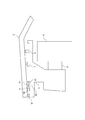
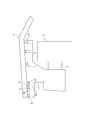
続いて、図3を参照して、実施の形態1にかかる搭乗部10a、10bの構成について説明する。図3は、実施の形態1にかかる搭乗部10a、10bの構成を示す正面断面図である。
搭乗部10a、10bのそれぞれは、ステップカバー3、車輪4、モータブラケット5、蝶番6、スイッチセンサ7、プランジャー8、及び駆動部9を有する。
モータブラケット5は、倒立二輪車1の側方に向かって、駆動部9及び車輪4を固定する。モータブラケット5は、その上部に平板状のベース部50を有している。ベース部50の上面には、倒立二輪車1の中心部側(内側、制御ユニット20側、ハンドル2側、蝶番6の軸部60側)から側方(外側、蝶番6の羽根部61、62の開閉側)に向かって、開き止め部品51、蝶番6、スイッチセンサ7、及びプランジャー8が順に取り付けられている。モータブラケット5は、ベース部50の一部が車輪4の上方に位置するような形状となっている。なお、前述のリンク22a、22bは、搭乗部10a、10bのモータブラケット5と連結される。
ステップカバー3は、ステップカバー3とベース部50の間に、開き止め部品51、蝶番6、スイッチセンサ7、及びプランジャー8が位置するように、ベース部50を覆う大きさとなっている。
蝶番6は、ステップカバー3がモータブラケット5に対して、倒立二輪車1の中心部側を軸として開閉可能となるように、ステップカバー3とモータブラケット5を連結する。例えば、蝶番6は、ベース部50の上面において、少なくとも左右方向の中心位置よりも、倒立二輪車1の中心部側に所定の距離寄った位置に設けられる。
具体的には、蝶番6は、軸部60、第1の羽根部61、及び第2の羽根部62を有する。第1の羽根部61の一端と第2の羽根部62の一端は、軸部60を介して連結されている。第1の羽根部61及び第2の羽根部62は、軸部60を介して回動可能となっている。第1の羽根部61は、一側がステップカバー3の下面と連結されている。第2の羽根部62は、一側が第1の羽根部61の他側(ステップカバー3と連結されていない側)と対向しており、他側がベース部50と連結されている。このような構成によって、第1の羽根部61に取り付けられたベースカバー3は、第2の羽根部62に取り付けられたモータブラケット5に対して開閉するように、蝶番6の軸部60を中心として回動可能となっている。
スイッチセンサ7は、外部からの押圧を検出するセンサである。スイッチセンサ7は、搭乗者がステップカバー3に搭乗して、ステップカバー3が押し下げられたときに、ステップカバー3の下面によって押圧される。スイッチセンサ7は、このようにしてステップカバー3から押圧(押下)されている間、押圧を通知する通知信号を、図示しない信号線を介して制御ユニット20のマイコンに出力する。制御ユニット20のマイコンは、スイッチセンサ7から通知信号の出力を受けている間、倒立二輪車1の倒立制御を実施する。これによって、搭乗者がステップカバー3に搭乗している間だけ、倒立二輪車1が倒立制御されて走行することになる。すなわち、スイッチセンサ7は、ステップカバー3からの押圧として、搭乗者の倒立二輪車1への搭乗を検出するセンサとして機能する。
制御ユニット20のマイコンは、搭乗部10a及び搭乗部10bの少なくともいずれかのスイッチセンサ7から通知信号の出力を受けているときに、倒立二輪車1の倒立制御を実施するようにしてもよい。しかしながら、好ましくは、搭乗者が搭乗中に倒立二輪車1が走行を開始してしまうことを防止するために、搭乗部10a及び搭乗部10bの両方のスイッチセンサ7から通知信号の出力を受けているときに、倒立二輪車1の倒立制御を実施するとよい。これによれば、搭乗者が倒立二輪車1に搭乗する際の安全性を、より向上することができる。
プランジャー8は、少なくともその一部に弾性体を有し、その弾性力によってステップカバー3を弾性支持する。ここで、プランジャー8の弾性体として、例えば、ゴム又はバネ等の弾性体のうち、任意の弾性体を採用するようにしてよい。プランジャー8は、ステップカバー3に搭乗者が搭乗することによって、ステップカバー3から所定値以上の荷重がかけられた場合に弾性変形(圧縮変形)するような弾性係数となっている。この所定値として、搭乗者が搭乗した際に作用すると考えられる任意の荷重を予め定めることができる。これによって、ステップカバー3の重みによってスイッチセンサ7が押下されてしまうことを防止しつつ、搭乗者がステップカバー3に搭乗した際には、プランジャー8が弾性変形して、スイッチセンサ7がステップカバー3によって押下されるようにすることができる。
ここでは、プランジャー8がスイッチセンサ7よりも倒立二輪車1の側方に配置される場合について例示したが、プランジャー8がスイッチセンサ7よりも倒立二輪車1の中央側に配置されるようにしてもよい。すなわち、プランジャー8は、蝶番6とスイッチセンサ7の間に配置されていてもよい。また、搭乗部10a、10bのそれぞれに、1つのプランジャー8を有する場合について例示したが、複数のプランジャー8を有するようにしてもよい。
駆動部9は、制御ユニット20のマイコンからの制御に応じて車輪4を回転させる。駆動部9は、図示しないモータ及び減速機を有する。駆動部9は、制御ユニット20のマイコンからの制御に応じて、減速機によってモータのトルクを増加させて車輪4を回転させる。
ステップカバー3とベース部50のそれぞれは、蝶番6との連結部よりも倒立二輪車1の中心部側に向かって延びる延部を有している。開き止め部品51は、ベース部50の延部の上面に取り付けられている。開き止め部品51は、例えば、ベース部50における倒立二輪車1の中心部側の端部の上面に取り付けられる。これによれば、ステップカバー3がベース部50に対して開くときに、ステップカバー3の延部が、ベース部50の延部の開き止め部品51に接触し、必要以上にステップカバー3が開くことを防止することができる。そのため、ステップカバー3とベース部50の間の開口部の広がりを抑止して、ステップカバー3とベース部50の間の空間における防塵性を向上することができる。これによれば、例えば、ステップカバー3とベース部50の間に配設置された各要素6~8の損傷の防止、蝶番6の第1の羽根部61及び第2の羽根部62の間に異物が入り込むことによるステップカバー3の開閉の阻害、又は、スイッチカバー3とスイッチセンサ7間に異物が入り込むことによる不正な搭乗検出等を防止することができる。
ここで、開き止め部品51は、例えば、直方体、円柱、又は半球等の任意の形状としてよい。また、開き止め部品51は、倒立二輪車1の中心部側におけるベース部50の縁部に沿って、任意の数、設けられるようにしてもよい。
なお、ステップカバー3とベース部50のそれぞれにおいて、延部を有さない構成としてもよい。この場合、倒立二輪車1は、ベース部50の延部に取り付けられる開き止め部品51も有さない構成となる。例えば、ステップカバー3に延部を有するようにした場合は、ステップカバー3の延部は不感帯となってしまう。これに対して、ステップカバー3に延部を有さない構成とすることで、その不感帯を無くすことができ、搭乗者検出の精度を向上させることができる。
以上に説明した構成によれば、搭乗者がステップカバー3に搭乗した際には、ステップカバー3が蝶番6を中心として回動し、ステップカバー3がプランジャー8を圧縮変形させ、スイッチセンサ7に対して押し下がる。スイッチセンサ7は、押し下がったステップカバー3によって押下されて通知信号を制御ユニット20のマイコンに出力する。そして、制御ユニット20のマイコンは、スイッチセンサ7から通知信号の出力を受けている間、倒立二輪車1の倒立制御を実施する。これによって、搭乗者が倒立二輪車1に搭乗している間のみ、倒立二輪車1の倒立二輪車1が実施される。
ここで、本実施の形態1では、ステップカバー3とモータブラケット5が蝶番6で連結されている。これによれば、ステップカバー3における不感帯は、蝶番6の軸部60の直上のみに制限される。そのため、本実施の形態1によれば、搭乗者検出の不感帯を減少することができるため、搭乗者を検出する精度を向上することができる。
<発明の実施の形態2>
続いて、本発明の実施の形態2について説明する。なお、本実施の形態2にかかる倒立二輪車1の概略構成及び構成については、図1及び図2を参照して説明した実施の形態1にかかる倒立二輪車1の概略構成及び構成と同様であるため、その説明は省略する。
続いて、本発明の実施の形態2について説明する。なお、本実施の形態2にかかる倒立二輪車1の概略構成及び構成については、図1及び図2を参照して説明した実施の形態1にかかる倒立二輪車1の概略構成及び構成と同様であるため、その説明は省略する。
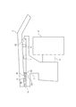
図4を参照して、実施の形態2にかかる搭乗部10a、10bの構成について説明する。図4は、実施の形態2にかかる搭乗部10a、10bの構成を示す正面断面図である。
本実施の形態2にかかる搭乗部10a、10bのそれぞれは、実施の形態1にかかる搭乗部10a、10bのそれぞれと比較して、さらに、防塵部品52を有する。
防塵部品52は、蝶番6、スイッチセンサ7、及びプランジャー8よりも、倒立二輪車1の側方で、ベース部50の上面に取り付けられている。防塵部品52は、例えば、ベース部50における倒立二輪車1の側方の端部の上面に取り付けられる。ここで、防塵部品52は、任意の形状としてよい。
これによれば、ステップカバー3とベース部50の間の空間に対して、倒立二輪車1の側方から通じる開口部の大きさを低減することができる。すなわち、ステップカバー3とベース部50の間の空間(倒立二輪車1内部)に対する防塵性を向上することができる。
また、防塵部品52は、図5に示すように、搭乗者がステップカバー3に搭乗して、ステップカバー3が押し下げられた場合に、その上面とステップカバー3の下面が密着するような高さとなっている。
これによれば、搭乗者がステップカバー3に搭乗して、倒立二輪車1が倒立制御によって走行しているときには、ステップカバー3とベース部50の間の空間に対して、倒立二輪車1の側方から通じる開口部を無くすことができる。よって、倒立二輪車1が走行することで巻き上げられる粉塵等の倒立二輪車1内部への流入を効果的に防止し、防塵性を向上することができる。
また、防塵部品52に代えて、図6に示すような防塵部品53を有するようにしてもよい。防塵部品53は、防塵部品52と異なる点として、搭乗者がステップカバー3に搭乗しておらず、ステップカバー3が押し下げられていない場合であっても、その上面とステップカバー3の下面が密着するような高さとなっている。
これによれば、搭乗者がステップカバー3に搭乗しておらず、ステップカバー3が押し下げられていない場合であっても、ステップカバー3とベース部50の間の空間に対して、倒立二輪車1の側方から通じる開口部を無くすことができるため、より防塵性を向上することができる。
また、図7に示すように、防塵部品53は、搭乗者がステップカバー3に搭乗して、ステップカバー3の押し下げられた場合に、ステップカバー3の下面から与えられる押圧に応じて弾性変形するように、少なくともその一部が任意の弾性体によって構成されている。防塵部品53は、図7に示すように、搭乗者がステップカバー3に搭乗して、ステップカバー3が押し下げられた場合であっても、その上面とステップカバー3の下面が密着した状態を維持するように弾性変形する。
これによれば、倒立二輪車1が走行することで巻き上げられる粉塵等の倒立二輪車1内部への流入も防止することができる。すなわち、図6及び図7に示す防塵部品53によれば、搭乗者がステップカバー3に搭乗して、ステップカバー3が押し下げられているか否かに関わらず、防塵機能を担保することができる。
以上に説明したように、本実施の形態2では、蝶番6の羽根部61、62の開閉側(倒立二輪車1の側方側)におけるモータブラケット5とステップカバー3の間に位置するように、モータブラケット5の上面に取り付けられた防塵部品52又は53を有するようにしている。これによれば、モータブラケット5とステップカバー3の間の空間に対する防塵性を向上することができる。
<発明の実施の形態3>
続いて、実施の形態3について説明する。なお、本実施の形態3にかかる倒立二輪車1の概略構成及び構成については、図1及び図2を参照して説明した実施の形態1にかかる倒立二輪車1の概略構成及び構成と同様であるため、その説明は省略する。
続いて、実施の形態3について説明する。なお、本実施の形態3にかかる倒立二輪車1の概略構成及び構成については、図1及び図2を参照して説明した実施の形態1にかかる倒立二輪車1の概略構成及び構成と同様であるため、その説明は省略する。
図8を参照して、実施の形態3にかかる搭乗部10a、10bの構成について説明する。図8は、実施の形態3にかかる搭乗部10a、10bの構成を示す図である。
搭乗部10a、10bのそれぞれは、ステップカバー3、蝶番6、スイッチセンサ7、及びプランジャー8のそれぞれを一対有する。言い換えると、搭乗部10a、10bのそれぞれは、ステップカバー3、蝶番6、スイッチセンサ7、及びプランジャー8のそれぞれを2式有する。以下、一式のステップカバー3、蝶番6、スイッチセンサ7、及びプランジャー8を、ステップカバー3a、蝶番6a、スイッチセンサ7a、及びプランジャー8aと呼び、もう一式をステップカバー3b、蝶番6b、スイッチセンサ7b、及びプランジャー8bと呼ぶ。
ステップカバー3a、蝶番6a、スイッチセンサ7a、及びプランジャー8aと、ステップカバー3b、蝶番6b、スイッチセンサ7b、及びプランジャー8bは、ベース部50の上面において、蝶番6aの軸部60側と蝶番6bの軸部60側が対向するように対称的に配置されている。すなわち、ステップカバー3aとベース部50の間の開口部(蝶番6aの羽根部61、62の開閉側)が倒立二輪車1の側方を向いており、ステップカバー3bとベース部50の間の開口部(蝶番6bの羽根部61、62の開閉側)が倒立二輪車1の中心部側を向くような配置となっている。
これによれば、例えば、ステップカバー3aでは、蝶番6aの軸部60よりも倒立二輪車1の中心部側の不感帯となってしまう範囲を、ステップカバー3bにおける感帯とすることができる。また、逆に、ステップカバー3bでは、蝶番6aの軸部60よりも倒立二輪車1の中心部側の不感帯となってしまう範囲を、ステップカバー3aにおける感帯とすることができる。そのため、搭乗部検出における不感帯を、より減少することができる。
ここで、実施の形態3では、制御ユニット20のマイコンは、スイッチセンサ7a、7bのうち、少なくともいずれか一方から通知信号の出力を受けているときに、倒立二輪車1の倒立制御を実施するようにすればよい。また、好ましくは、搭乗者が搭乗中に倒立二輪車1が走行を開始してしまうことを防止するためには、搭乗部10aのスイッチセンサ7a、7bの少なくともいずれか一方からと、搭乗部10bのスイッチセンサ7a、7bの少なくともいずれか一方からの両方から通信信号の出力を受けているときに、倒立二輪車1の倒立制御を実施するとよい。
ここで、図9に示すように、好ましくは、蝶番6aと蝶番6bの間の距離は、搭乗者の足100のサイズに対して十分に小さい距離とするとよい。そのようにすることで、蝶番6aと蝶番6bの間の不感帯を、より減少することができる。例えば、蝶番6aと蝶番6bの間の距離は、平均的な足幅の数パーセント又は十数パーセントとする、もしくは、数センチとする等して任意の距離を決定するようにしてよい。
以上に説明したように、本実施の形態3では、ステップカバー3及びスイッチセンサ7等を一対備えるようにし、ステップカバー3a、3bのそれぞれは、蝶番6aの軸部60a側と蝶番6bの軸部60b側が対向するようにモータブラケット5に連結されるようにしている。これによれば、蝶番6aの軸部60a側のステップカバー3aでは不感帯となってしまう範囲を、ステップカバー3bの感帯として無くすことができる。また、蝶番6bの軸部60b側のステップカバー3bでは不感帯となってしまう範囲を、ステップカバー3aの感帯として無くすことができる。すなわち、搭乗者検出の不感帯を減少させることができ、搭乗者を検出する精度を向上することができる。
<発明の実施の形態4>
続いて、実施の形態4について説明する。なお、本実施の形態4にかかる倒立二輪車1の概略構成及び構成については、図1及び図2を参照して説明した実施の形態1にかかる倒立二輪車1の概略構成及び構成と同様であるため、その説明は省略する。
続いて、実施の形態4について説明する。なお、本実施の形態4にかかる倒立二輪車1の概略構成及び構成については、図1及び図2を参照して説明した実施の形態1にかかる倒立二輪車1の概略構成及び構成と同様であるため、その説明は省略する。
図10を参照して、実施の形態4にかかる搭乗部10a、10bの構成について説明する。図10は、実施の形態4にかかる搭乗部10a、10bの構成を示す図である。
本実施の形態4にかかる搭乗部10a、10bのそれぞれは、実施の形態1にかかる搭乗部10a、10bのそれぞれと比較して、蝶番6、スイッチセンサ7、及びプランジャー8の設置順序が逆となっている。すなわち、本実施の形態3では、ベース部50の上面には、倒立二輪車1の中心部側から側方に向かって、プランジャー8、スイッチセンサ7、及び蝶番6が順に取り付けられている。
このように、蝶番6の軸部60の直上の不感帯が倒立二輪車1の外側に位置するように、プランジャー8、スイッチセンサ7、及び蝶番6のそれぞれをベース部50の上面に配置するようにしてもよい。言い換えると、本実施の形態4では、蝶番6は、ステップカバー3がモータブラケット5に対して、倒立二輪車1の外側を軸として開閉可能となるように、倒立二輪車1の外側においてステップカバー3とモータブラケット5を連結する。例えば、蝶番6は、ベース部50の上面において、少なくとも左右方向の中心位置よりも、倒立二輪車1の外側に所定の距離寄った位置に設けられる。
ここで、本実施の形態4にかかる搭乗部10a、10bの構成は、図11に示すように、倒立二輪車1のハンドル2を、ショートタイプハンドル21とした構成において非常に有効である。図1に示す倒立二輪車1のハンドル2は、搭乗者が両手でハンドル2の取っ手部分を掴み操作するロングタイプハンドルであるのに対し、図11に示す倒立二輪車1のハンドル21は、搭乗者がハンドル21のパッド部24を両足の太腿で挟み操作するショートタイプハンドルである。
倒立二輪車1がショートタイプハンドル21である場合、搭乗者は、ハンドル21を両足で挟持するために倒立二輪車1の中心部側寄りに搭乗する傾向がある。そのため、本実施の形態4にかかる搭乗部10a、10bのように不感帯を外側(タイヤ側)に配置することで、搭乗者が感帯に足を乗せる可能性を向上することができる。すなわち、全ての実施の形態は、図11に示すショートタイプハンドル21の倒立二輪車1にも適用することができ、特に本実施の形態4を適用した場合には、搭乗者検出の精度を向上することができる。
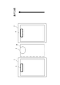
ここで、図12に示すように、搭乗者が左右方向に荷重を作用させておらず、左右方向に倒立二輪車1の姿勢角を傾斜させていない非旋回動作時に対して、図13に示すように、搭乗者が左右方向に荷重を作用させて、左右方向に倒立二輪車1の姿勢角を傾斜させた旋回時動作時には、ステップカバー3と制御ユニット20との間のクリアランス110が小さくなる。そのため、ステップカバー3における倒立二輪車1の中心部側が制御ユニット20と干渉しないように、ステップカバー3の形状を設計するとよい。
以上に説明したように、本実施の形態4では、搭乗者が両足の腿部で挟持するハンドル21と、一対の搭乗部10a、10bを備える構成において、ステップカバー3のそれぞれは、蝶番6の羽根部61、62の開閉側がハンドル21を向くようにモータブラケット5に連結されている。
これによれば、搭乗者が足を載置し易いハンドル21寄りに、スイッチセンサ7等の上方に位置するステップカバー3の感帯を位置することになる。そのため、搭乗者が感帯に足を乗せる可能性を向上して、搭乗者検出の精度を向上することができる。
<発明の実施の形態5>
続いて、実施の形態5について説明する。なお、本実施の形態5にかかる倒立二輪車1の概略構成及び構成については、図1及び図2を参照して説明した実施の形態1にかかる倒立二輪車1の概略構成及び構成と同様であるため、その説明は省略する。
続いて、実施の形態5について説明する。なお、本実施の形態5にかかる倒立二輪車1の概略構成及び構成については、図1及び図2を参照して説明した実施の形態1にかかる倒立二輪車1の概略構成及び構成と同様であるため、その説明は省略する。
上述した実施の形態1~4では、蝶番6の羽根部61、62の開閉側が倒立二輪車1の左方又は右方を向くように、ステップカバー3の左方又は右方に蝶番6を配置する場合について説明したが、蝶番6の羽根部61、62の開閉側が倒立二輪車1の前方又は後方を向くように、ステップカバー3の前方又は後方に蝶番6を配置するようにしてもよい。
図14及び図15を参照して、実施の形態5にかかる搭乗部10a、10bの構成について説明する。図14及び図15は、実施の形態5にかかる搭乗部10a、10bの構成を示す図である。
図14に示すように、本実施の形態5の一態様として、蝶番6をベース部50の後方に取り付けることも可能である。すなわち、ステップカバー3は、蝶番6の羽根部61、62の開閉側が倒立二輪車1の前方を向くようにベース部50に連結されている。よって、ベース部50の上面には、倒立二輪車1の後方から前方に向かって、蝶番6、スイッチセンサ7、及びプランジャー8が順に取り付けられている。例えば、蝶番6は、ベース部50の上面において、少なくとも前後方向の中心位置よりも、倒立二輪車1の後方側に所定の距離寄った位置に設けられる。また、例えば、蝶番6は、ベース部50の上面における後方の端部に設けられる。
これによれば、ステップカバー3の前方寄りに、スイッチセンサ7等の上方に位置するステップカバー3の感帯を位置することになる。そのため、搭乗者にステップカバー3の前方寄りに足を乗せる傾向がある場合、搭乗者が感帯に足を乗せる可能性を向上して、搭乗者検出の精度を向上することができる。
また、図15に示すように、本実施の形態5の他の態様として、蝶番6をベース部50の前方に取り付けることも可能である。すなわち、ステップカバー3は、蝶番6の羽根部61、62の開閉側が倒立二輪車1の後方を向くようにベース部50に連結されている。よって、ベース部50の上面には、倒立二輪車1の前方から後方に向かって、蝶番6、スイッチセンサ7、及びプランジャー8が順に取り付けられている。例えば、蝶番6は、ベース部50の上面において、少なくとも前後方向の中心位置よりも、倒立二輪車1の前方側に所定の距離寄った位置に設けられる。また、例えば、蝶番6は、ベース部50の上面における前方の端部に設けられる。
これによれば、ステップカバー3の後方寄りに、スイッチセンサ7等の上方に位置するステップカバー3の感帯を位置することになる。そのため、搭乗者にステップカバー3の後方寄りに足を乗せる傾向がある場合、搭乗者が感帯に足を乗せる可能性を向上して、搭乗者検出の精度を向上することができる。
以上に説明したように、本実施の形態5では、ステップカバー3は、蝶番6の羽根部61、62の開閉側が倒立二輪車1の前方又は後方を向くようにモータブラケット5に連結されている。これによれば、搭乗者にステップカバー3の前方又は後方寄りに足を乗せる傾向がある場合、搭乗者が感帯に足を乗せる可能性を向上して、搭乗者検出の精度を向上することができる。すなわち、このように、搭乗者の乗り方に合わせてステップカバー3における不感帯(又は感帯)の位置を、所望の位置に配置するようにしてもよい。
なお、本発明は上記実施の形態に限られたものではなく、趣旨を逸脱しない範囲で適宜変更することが可能である。
例えば、本実施の形態1~5は、任意の2つ以上を組み合わせて実施することも可能である。例えば、実施の形態3~5において、ベース部50上に防塵部品52又は53を設けるようにしてもよく、実施の形態3~5において、ベース部50上に開き止め部品51を有するようにしてもよい。
この出願は、2012年10月26日に出願された日本出願特願2012-236326を基礎とする優先権を主張し、その開示の全てをここに取り込む。
1 倒立二輪車
2 ハンドル
3 ステップカバー
4 車輪
5 モータブラケット
6 蝶番
7 スイッチセンサ
8 プランジャー
9 駆動部
10a、10b 搭乗部
20 制御ユニット
22a、22b リンク
23a、23b、23c、23d、23e、23f リンク回転関節部
24 パッド部
50 ベース部
51 開き止め部品
52、53 防塵部品
60 軸部
61 第1の羽根部
62 第2の羽根部
2 ハンドル
3 ステップカバー
4 車輪
5 モータブラケット
6 蝶番
7 スイッチセンサ
8 プランジャー
9 駆動部
10a、10b 搭乗部
20 制御ユニット
22a、22b リンク
23a、23b、23c、23d、23e、23f リンク回転関節部
24 パッド部
50 ベース部
51 開き止め部品
52、53 防塵部品
60 軸部
61 第1の羽根部
62 第2の羽根部
Claims (7)
- 車輪と、
車輪を駆動可能に保持するベースと、
前記ベースの上部に連結され、搭乗者が搭乗するステップカバーと、
前記ベースの上部に連結され、前記ステップカバーを弾性支持する弾性要素と、
前記ベースと前記ステップカバーの間に設けられ、前記搭乗者が搭乗することで前記弾性要素が弾性変形して前記ステップカバーが押し下げられることによる前記ステップカバーからの押圧を検出する検出部と、
前記検出部による押圧の検出に応じて、前記車輪を駆動して倒立制御を行う制御部と、を備え、
前記ステップカバーは、前記ベースに蝶番で連結されていることを特徴とする、
倒立型移動体。 - 前記倒立型移動体は、さらに、前記蝶番の羽根部の開閉側における前記ベースと前記ステップカバーの間に位置するように、前記ベースの上面に取り付けられた防塵部を備える、
請求項1に記載の倒立型移動体。 - 前記防塵部は、前記ステップカバーが押し下げられていない場合、その上面が前記ステップカバーの下面と接触し、前記ステップカバーが押し下げられた場合、前記ステップカバーの下面との接触を維持したまま弾性変形するように、少なくとも一部が弾性体によって構成される、
請求項2に記載の倒立型移動体。 - 前記倒立型移動体は、前記ステップカバー、前記弾性要素、及び前記検出部を一対備え、
前記ステップカバーのそれぞれは、一方の蝶番の軸部側と他方の蝶番の軸部側が対向するように前記ベースに連結されている、
請求項1乃至3のいずれか1項に記載の倒立型移動体。 - 前記蝶番は、前記ベースの外周に設けられる、
請求項1乃至3のいずれか1項に記載の倒立型移動体。 - 前記ステップカバーは、前記蝶番の羽根部の開閉側が前記倒立型移動体の前方又は後方を向くように前記ベースに連結されている、
請求項1乃至5のいずれか1項に記載の倒立型移動体。 - 前記ステップカバー及び前記ベースのそれぞれは、前記蝶番との連結部よりも前記蝶番の軸部側にさらに延びた延部を有し、
前記ベースは、前記延部の上面に、前記ステップカバーが前記ベースに対して前記蝶番を軸として開いた場合に、前記ステップカバーの延部が接触する開き止め部を有する、
請求項1乃至6のいずれか1項に記載の倒立型移動体。
Priority Applications (3)
| Application Number | Priority Date | Filing Date | Title |
|---|---|---|---|
| US14/438,403 US9592875B2 (en) | 2012-10-26 | 2013-09-30 | Inverted vehicle |
| CN201380055574.2A CN104755364A (zh) | 2012-10-26 | 2013-09-30 | 倒立式移动体 |
| EP13849230.1A EP2913258A4 (en) | 2012-10-26 | 2013-09-30 | REVERSED MOVABLE OBJECT |
Applications Claiming Priority (2)
| Application Number | Priority Date | Filing Date | Title |
|---|---|---|---|
| JP2012-236326 | 2012-10-26 | ||
| JP2012236326A JP5929708B2 (ja) | 2012-10-26 | 2012-10-26 | 倒立型移動体 |
Publications (1)
| Publication Number | Publication Date |
|---|---|
| WO2014064887A1 true WO2014064887A1 (ja) | 2014-05-01 |
Family
ID=50544273
Family Applications (1)
| Application Number | Title | Priority Date | Filing Date |
|---|---|---|---|
| PCT/JP2013/005824 Ceased WO2014064887A1 (ja) | 2012-10-26 | 2013-09-30 | 倒立型移動体 |
Country Status (5)
| Country | Link |
|---|---|
| US (1) | US9592875B2 (ja) |
| EP (1) | EP2913258A4 (ja) |
| JP (1) | JP5929708B2 (ja) |
| CN (1) | CN104755364A (ja) |
| WO (1) | WO2014064887A1 (ja) |
Cited By (5)
| Publication number | Priority date | Publication date | Assignee | Title |
|---|---|---|---|---|
| GB2533078A (en) * | 2014-09-03 | 2016-06-15 | Artemev Timur | Entity presence detection system for a self-balancing powered unicycle device |
| JP6086636B1 (ja) * | 2015-09-30 | 2017-03-01 | 江西迪安新能源▲動▼力有限公司 | 電動二輪均衡スクーター |
| EP3196108A4 (en) * | 2014-09-15 | 2019-01-02 | Changzhou Airwheel Technology Co., Ltd. | Self-balancing double-wheeled electrical scooter |
| US10207763B2 (en) | 2014-02-04 | 2019-02-19 | Timur ARTEMEV | Usage detection system for a self-balancing powered unicycle device |
| US10286971B2 (en) | 2014-09-15 | 2019-05-14 | Changzhou Airwheel Technology Co., Ltd. (Cn) | Self-balancing double-wheeled electrical scooter |
Families Citing this family (16)
| Publication number | Priority date | Publication date | Assignee | Title |
|---|---|---|---|---|
| KR101529971B1 (ko) * | 2014-01-27 | 2015-06-26 | 주식회사 로보쓰리 | 족동형 조향장치가 장착된 백팩형 셀프 밸런싱 스쿠터 |
| CN203893878U (zh) * | 2014-06-24 | 2014-10-22 | 纳恩博(天津)科技有限公司 | 动平衡车的驾驶模式检测装置 |
| USD774600S1 (en) * | 2015-03-10 | 2016-12-20 | Hangzhou Notebike Technology Co., Ltd. | Electric balancing scooter |
| CN205220929U (zh) * | 2015-09-17 | 2016-05-11 | 何武 | 电动平衡车及其踏板组件 |
| US10252724B2 (en) * | 2015-09-24 | 2019-04-09 | P&N Phc, Llc | Portable two-wheeled self-balancing personal transport vehicle |
| CN106564546B (zh) * | 2015-10-10 | 2020-08-14 | 杭州骑客智能科技有限公司 | 全姿态电动平衡扭扭车 |
| WO2017054764A1 (zh) * | 2015-10-01 | 2017-04-06 | 杭州骑客智能科技有限公司 | 人机互动体感车 |
| WO2018126635A1 (zh) * | 2017-01-04 | 2018-07-12 | 杭州骑客智能科技有限公司 | 人机互动体感车 |
| KR101800679B1 (ko) * | 2016-01-14 | 2017-11-23 | 주식회사 로보쓰리 | 족동형 트위스트 조향식 핸즈프리 밸런싱 스쿠터 |
| CN106240401A (zh) * | 2016-07-29 | 2016-12-21 | 北京小米移动软件有限公司 | 平衡车的控制方法和装置 |
| CN106218772A (zh) * | 2016-08-09 | 2016-12-14 | 尚艳燕 | 一种电动平衡车及其踏板组件 |
| CN106005139A (zh) * | 2016-08-09 | 2016-10-12 | 尚艳燕 | 一种电动平衡车及其踏板组件 |
| CN106184511B (zh) * | 2016-08-09 | 2019-11-22 | 尚艳燕 | 一种电动平衡车及其踏板组件 |
| JP6524991B2 (ja) * | 2016-12-09 | 2019-06-05 | トヨタ自動車株式会社 | 訓練システム、および足関節トルク推定方法 |
| USD816778S1 (en) * | 2017-03-14 | 2018-05-01 | Zhejiang Raymond Way Electronic Technology Co., Ltd | Electric balance scooter |
| USD826087S1 (en) * | 2017-09-04 | 2018-08-21 | Toyota Jidosha Kabushiki Kaisha | Personal transportation vehicle |
Citations (4)
| Publication number | Priority date | Publication date | Assignee | Title |
|---|---|---|---|---|
| JP2001063510A (ja) * | 1999-08-26 | 2001-03-13 | Nissan Motor Co Ltd | 車両の衝撃緩和構造 |
| JP2004510637A (ja) | 2000-10-13 | 2004-04-08 | デカ・プロダクツ・リミテッド・パートナーシップ | 個人用輸送車の制御 |
| WO2012025969A1 (ja) * | 2010-08-27 | 2012-03-01 | トヨタ自動車株式会社 | 乗降判定装置及び乗降判定方法 |
| JP2012126224A (ja) * | 2010-12-15 | 2012-07-05 | Bosch Corp | 倒立振子型移動体 |
Family Cites Families (11)
| Publication number | Priority date | Publication date | Assignee | Title |
|---|---|---|---|---|
| GB139924A (en) * | 1919-04-15 | 1920-03-18 | George Addy | Improvements in footboards for use on motor cycles |
| US7546889B2 (en) * | 1993-02-24 | 2009-06-16 | Deka Products Limited Partnership | Guided control of a transporter |
| US5319996A (en) * | 1993-08-13 | 1994-06-14 | Kransco | Debris resistant foot pedal switch assembly |
| US7275607B2 (en) * | 1999-06-04 | 2007-10-02 | Deka Products Limited Partnership | Control of a personal transporter based on user position |
| US6866107B2 (en) * | 2000-10-13 | 2005-03-15 | Deka Products Limited Partnership | Method and device for battery load sharing |
| WO2004007233A2 (en) * | 2002-07-12 | 2004-01-22 | Deka Products Limited Partnership | Motion control for a transporter |
| JP3981733B2 (ja) | 2003-09-17 | 2007-09-26 | 独立行政法人産業技術総合研究所 | 平行2輪乗用台車 |
| JP4691912B2 (ja) * | 2004-06-16 | 2011-06-01 | トヨタ自動車株式会社 | 不安定走行装置 |
| JP4650327B2 (ja) * | 2005-04-14 | 2011-03-16 | トヨタ自動車株式会社 | 同軸二輪車 |
| CN101353070A (zh) * | 2005-04-14 | 2009-01-28 | 丰田自动车株式会社 | 共轴两轮车辆 |
| JP5062361B2 (ja) * | 2010-03-12 | 2012-10-31 | トヨタ自動車株式会社 | 移動体 |
-
2012
- 2012-10-26 JP JP2012236326A patent/JP5929708B2/ja active Active
-
2013
- 2013-09-30 CN CN201380055574.2A patent/CN104755364A/zh active Pending
- 2013-09-30 WO PCT/JP2013/005824 patent/WO2014064887A1/ja not_active Ceased
- 2013-09-30 EP EP13849230.1A patent/EP2913258A4/en not_active Withdrawn
- 2013-09-30 US US14/438,403 patent/US9592875B2/en not_active Expired - Fee Related
Patent Citations (4)
| Publication number | Priority date | Publication date | Assignee | Title |
|---|---|---|---|---|
| JP2001063510A (ja) * | 1999-08-26 | 2001-03-13 | Nissan Motor Co Ltd | 車両の衝撃緩和構造 |
| JP2004510637A (ja) | 2000-10-13 | 2004-04-08 | デカ・プロダクツ・リミテッド・パートナーシップ | 個人用輸送車の制御 |
| WO2012025969A1 (ja) * | 2010-08-27 | 2012-03-01 | トヨタ自動車株式会社 | 乗降判定装置及び乗降判定方法 |
| JP2012126224A (ja) * | 2010-12-15 | 2012-07-05 | Bosch Corp | 倒立振子型移動体 |
Non-Patent Citations (1)
| Title |
|---|
| See also references of EP2913258A4 |
Cited By (6)
| Publication number | Priority date | Publication date | Assignee | Title |
|---|---|---|---|---|
| US10207763B2 (en) | 2014-02-04 | 2019-02-19 | Timur ARTEMEV | Usage detection system for a self-balancing powered unicycle device |
| GB2533078A (en) * | 2014-09-03 | 2016-06-15 | Artemev Timur | Entity presence detection system for a self-balancing powered unicycle device |
| EP3196108A4 (en) * | 2014-09-15 | 2019-01-02 | Changzhou Airwheel Technology Co., Ltd. | Self-balancing double-wheeled electrical scooter |
| US10286971B2 (en) | 2014-09-15 | 2019-05-14 | Changzhou Airwheel Technology Co., Ltd. (Cn) | Self-balancing double-wheeled electrical scooter |
| JP6086636B1 (ja) * | 2015-09-30 | 2017-03-01 | 江西迪安新能源▲動▼力有限公司 | 電動二輪均衡スクーター |
| JP2017065661A (ja) * | 2015-09-30 | 2017-04-06 | 江西迪安新能源▲動▼力有限公司 | 電動二輪均衡スクーター |
Also Published As
| Publication number | Publication date |
|---|---|
| US9592875B2 (en) | 2017-03-14 |
| JP2014084051A (ja) | 2014-05-12 |
| EP2913258A1 (en) | 2015-09-02 |
| EP2913258A4 (en) | 2016-07-06 |
| CN104755364A (zh) | 2015-07-01 |
| US20150298756A1 (en) | 2015-10-22 |
| JP5929708B2 (ja) | 2016-06-08 |
Similar Documents
| Publication | Publication Date | Title |
|---|---|---|
| JP5929708B2 (ja) | 倒立型移動体 | |
| RU2692412C1 (ru) | Транспортное средство с человекомашинным взаимодействием, работающее в зависимости от положения тела пользователя | |
| TWI552891B (zh) | 刹車油門組合裝置及採用該刹車油門組合裝置之汽車 | |
| EP3566936A1 (en) | Man-machine interaction somatosensory vehicle | |
| JP4599907B2 (ja) | 走行装置 | |
| US10120391B2 (en) | Self-balancing enclosed motorcycle | |
| JP2002145128A (ja) | ローリフトトラック | |
| KR101907430B1 (ko) | 삼륜 탑승 기구 | |
| KR102468606B1 (ko) | 탑승형 서비스 로봇 및 그 제어방법 | |
| JP5989474B2 (ja) | 電動台車 | |
| JP6327095B2 (ja) | バランス訓練機 | |
| JP2012086683A (ja) | 移動体 | |
| JP6233266B2 (ja) | バランス訓練機 | |
| KR200489489Y1 (ko) | 안전기능이 구비된 센터오픈타입 엘리베이터 도어 | |
| JP4631381B2 (ja) | 小型電動車両の緊急停止装置 | |
| KR100762791B1 (ko) | 차량용 발판장치 | |
| JP4923418B2 (ja) | エレベータのドア装置 | |
| JP6107635B2 (ja) | 同軸二輪車 | |
| JP5272952B2 (ja) | 移動体 | |
| KR101272604B1 (ko) | 탑승형 로봇 및 이를 포함하는 탑승형 로봇 운용 시스템 | |
| JP5617705B2 (ja) | 移動体 | |
| KR20160138803A (ko) | 탑승 감지 제동 제어형 전동 유모차 | |
| JP6790806B2 (ja) | 同軸二輪車 | |
| KR100783577B1 (ko) | 차량용 승객 보호장치 | |
| KR100916790B1 (ko) | 컬럼 수축시 간섭 회피형 틸트 레버 |
Legal Events
| Date | Code | Title | Description |
|---|---|---|---|
| 121 | Ep: the epo has been informed by wipo that ep was designated in this application |
Ref document number: 13849230 Country of ref document: EP Kind code of ref document: A1 |
|
| WWE | Wipo information: entry into national phase |
Ref document number: 14438403 Country of ref document: US |
|
| NENP | Non-entry into the national phase |
Ref country code: DE |
|
| REEP | Request for entry into the european phase |
Ref document number: 2013849230 Country of ref document: EP |
|
| WWE | Wipo information: entry into national phase |
Ref document number: 2013849230 Country of ref document: EP |