WO2014065120A1 - 充電コネクタ - Google Patents
充電コネクタ Download PDFInfo
- Publication number
- WO2014065120A1 WO2014065120A1 PCT/JP2013/077459 JP2013077459W WO2014065120A1 WO 2014065120 A1 WO2014065120 A1 WO 2014065120A1 JP 2013077459 W JP2013077459 W JP 2013077459W WO 2014065120 A1 WO2014065120 A1 WO 2014065120A1
- Authority
- WO
- WIPO (PCT)
- Prior art keywords
- connector
- case
- outer case
- hole
- seal
- Prior art date
- Legal status (The legal status is an assumption and is not a legal conclusion. Google has not performed a legal analysis and makes no representation as to the accuracy of the status listed.)
- Ceased
Links
Images


Classifications
-
- H—ELECTRICITY
- H01—ELECTRIC ELEMENTS
- H01R—ELECTRICALLY-CONDUCTIVE CONNECTIONS; STRUCTURAL ASSOCIATIONS OF A PLURALITY OF MUTUALLY-INSULATED ELECTRICAL CONNECTING ELEMENTS; COUPLING DEVICES; CURRENT COLLECTORS
- H01R13/00—Details of coupling devices of the kinds covered by groups H01R12/70 or H01R24/00 - H01R33/00
- H01R13/46—Bases; Cases
- H01R13/516—Means for holding or embracing insulating body, e.g. casing, hoods
-
- B—PERFORMING OPERATIONS; TRANSPORTING
- B60—VEHICLES IN GENERAL
- B60L—PROPULSION OF ELECTRICALLY-PROPELLED VEHICLES; SUPPLYING ELECTRIC POWER FOR AUXILIARY EQUIPMENT OF ELECTRICALLY-PROPELLED VEHICLES; ELECTRODYNAMIC BRAKE SYSTEMS FOR VEHICLES IN GENERAL; MAGNETIC SUSPENSION OR LEVITATION FOR VEHICLES; MONITORING OPERATING VARIABLES OF ELECTRICALLY-PROPELLED VEHICLES; ELECTRIC SAFETY DEVICES FOR ELECTRICALLY-PROPELLED VEHICLES
- B60L53/00—Methods of charging batteries, specially adapted for electric vehicles; Charging stations or on-board charging equipment therefor; Exchange of energy storage elements in electric vehicles
- B60L53/10—Methods of charging batteries, specially adapted for electric vehicles; Charging stations or on-board charging equipment therefor; Exchange of energy storage elements in electric vehicles characterised by the energy transfer between the charging station and the vehicle
- B60L53/14—Conductive energy transfer
- B60L53/16—Connectors, e.g. plugs or sockets, specially adapted for charging electric vehicles
-
- H—ELECTRICITY
- H01—ELECTRIC ELEMENTS
- H01R—ELECTRICALLY-CONDUCTIVE CONNECTIONS; STRUCTURAL ASSOCIATIONS OF A PLURALITY OF MUTUALLY-INSULATED ELECTRICAL CONNECTING ELEMENTS; COUPLING DEVICES; CURRENT COLLECTORS
- H01R13/00—Details of coupling devices of the kinds covered by groups H01R12/70 or H01R24/00 - H01R33/00
- H01R13/46—Bases; Cases
- H01R13/502—Bases; Cases composed of different pieces
- H01R13/504—Bases; Cases composed of different pieces different pieces being moulded, cemented, welded, e.g. ultrasonic welding, or swaged together
- H01R13/5045—Bases; Cases composed of different pieces different pieces being moulded, cemented, welded, e.g. ultrasonic welding, or swaged together different pieces being assembled by press-fit
-
- H—ELECTRICITY
- H01—ELECTRIC ELEMENTS
- H01R—ELECTRICALLY-CONDUCTIVE CONNECTIONS; STRUCTURAL ASSOCIATIONS OF A PLURALITY OF MUTUALLY-INSULATED ELECTRICAL CONNECTING ELEMENTS; COUPLING DEVICES; CURRENT COLLECTORS
- H01R13/00—Details of coupling devices of the kinds covered by groups H01R12/70 or H01R24/00 - H01R33/00
- H01R13/46—Bases; Cases
- H01R13/52—Dustproof, splashproof, drip-proof, waterproof, or flameproof cases
- H01R13/5202—Sealing means between parts of housing or between housing part and a wall, e.g. sealing rings
-
- H—ELECTRICITY
- H01—ELECTRIC ELEMENTS
- H01R—ELECTRICALLY-CONDUCTIVE CONNECTIONS; STRUCTURAL ASSOCIATIONS OF A PLURALITY OF MUTUALLY-INSULATED ELECTRICAL CONNECTING ELEMENTS; COUPLING DEVICES; CURRENT COLLECTORS
- H01R13/00—Details of coupling devices of the kinds covered by groups H01R12/70 or H01R24/00 - H01R33/00
- H01R13/46—Bases; Cases
- H01R13/52—Dustproof, splashproof, drip-proof, waterproof, or flameproof cases
- H01R13/5205—Sealing means between cable and housing, e.g. grommet
-
- H—ELECTRICITY
- H01—ELECTRIC ELEMENTS
- H01R—ELECTRICALLY-CONDUCTIVE CONNECTIONS; STRUCTURAL ASSOCIATIONS OF A PLURALITY OF MUTUALLY-INSULATED ELECTRICAL CONNECTING ELEMENTS; COUPLING DEVICES; CURRENT COLLECTORS
- H01R13/00—Details of coupling devices of the kinds covered by groups H01R12/70 or H01R24/00 - H01R33/00
- H01R13/46—Bases; Cases
- H01R13/52—Dustproof, splashproof, drip-proof, waterproof, or flameproof cases
- H01R13/5219—Sealing means between coupling parts, e.g. interfacial seal
-
- H—ELECTRICITY
- H01—ELECTRIC ELEMENTS
- H01R—ELECTRICALLY-CONDUCTIVE CONNECTIONS; STRUCTURAL ASSOCIATIONS OF A PLURALITY OF MUTUALLY-INSULATED ELECTRICAL CONNECTING ELEMENTS; COUPLING DEVICES; CURRENT COLLECTORS
- H01R13/00—Details of coupling devices of the kinds covered by groups H01R12/70 or H01R24/00 - H01R33/00
- H01R13/62—Means for facilitating engagement or disengagement of coupling parts or for holding them in engagement
- H01R13/627—Snap or like fastening
- H01R13/6275—Latching arms not integral with the housing
-
- H—ELECTRICITY
- H01—ELECTRIC ELEMENTS
- H01R—ELECTRICALLY-CONDUCTIVE CONNECTIONS; STRUCTURAL ASSOCIATIONS OF A PLURALITY OF MUTUALLY-INSULATED ELECTRICAL CONNECTING ELEMENTS; COUPLING DEVICES; CURRENT COLLECTORS
- H01R13/00—Details of coupling devices of the kinds covered by groups H01R12/70 or H01R24/00 - H01R33/00
- H01R13/66—Structural association with built-in electrical component
- H01R13/70—Structural association with built-in electrical component with built-in switch
- H01R13/701—Structural association with built-in electrical component with built-in switch the switch being actuated by an accessory, e.g. cover, locking member
-
- H—ELECTRICITY
- H01—ELECTRIC ELEMENTS
- H01R—ELECTRICALLY-CONDUCTIVE CONNECTIONS; STRUCTURAL ASSOCIATIONS OF A PLURALITY OF MUTUALLY-INSULATED ELECTRICAL CONNECTING ELEMENTS; COUPLING DEVICES; CURRENT COLLECTORS
- H01R2201/00—Connectors or connections adapted for particular applications
- H01R2201/26—Connectors or connections adapted for particular applications for vehicles
-
- Y—GENERAL TAGGING OF NEW TECHNOLOGICAL DEVELOPMENTS; GENERAL TAGGING OF CROSS-SECTIONAL TECHNOLOGIES SPANNING OVER SEVERAL SECTIONS OF THE IPC; TECHNICAL SUBJECTS COVERED BY FORMER USPC CROSS-REFERENCE ART COLLECTIONS [XRACs] AND DIGESTS
- Y02—TECHNOLOGIES OR APPLICATIONS FOR MITIGATION OR ADAPTATION AGAINST CLIMATE CHANGE
- Y02T—CLIMATE CHANGE MITIGATION TECHNOLOGIES RELATED TO TRANSPORTATION
- Y02T10/00—Road transport of goods or passengers
- Y02T10/60—Other road transportation technologies with climate change mitigation effect
- Y02T10/70—Energy storage systems for electromobility, e.g. batteries
-
- Y—GENERAL TAGGING OF NEW TECHNOLOGICAL DEVELOPMENTS; GENERAL TAGGING OF CROSS-SECTIONAL TECHNOLOGIES SPANNING OVER SEVERAL SECTIONS OF THE IPC; TECHNICAL SUBJECTS COVERED BY FORMER USPC CROSS-REFERENCE ART COLLECTIONS [XRACs] AND DIGESTS
- Y02—TECHNOLOGIES OR APPLICATIONS FOR MITIGATION OR ADAPTATION AGAINST CLIMATE CHANGE
- Y02T—CLIMATE CHANGE MITIGATION TECHNOLOGIES RELATED TO TRANSPORTATION
- Y02T10/00—Road transport of goods or passengers
- Y02T10/60—Other road transportation technologies with climate change mitigation effect
- Y02T10/7072—Electromobility specific charging systems or methods for batteries, ultracapacitors, supercapacitors or double-layer capacitors
-
- Y—GENERAL TAGGING OF NEW TECHNOLOGICAL DEVELOPMENTS; GENERAL TAGGING OF CROSS-SECTIONAL TECHNOLOGIES SPANNING OVER SEVERAL SECTIONS OF THE IPC; TECHNICAL SUBJECTS COVERED BY FORMER USPC CROSS-REFERENCE ART COLLECTIONS [XRACs] AND DIGESTS
- Y02—TECHNOLOGIES OR APPLICATIONS FOR MITIGATION OR ADAPTATION AGAINST CLIMATE CHANGE
- Y02T—CLIMATE CHANGE MITIGATION TECHNOLOGIES RELATED TO TRANSPORTATION
- Y02T90/00—Enabling technologies or technologies with a potential or indirect contribution to GHG emissions mitigation
- Y02T90/10—Technologies relating to charging of electric vehicles
- Y02T90/14—Plug-in electric vehicles
Definitions
- the present invention relates to a charging connector used when charging a battery mounted on a vehicle such as an electric vehicle or a hybrid electric vehicle.
- a charging connector is used to charge a battery mounted on a vehicle such as an electric vehicle (EV) or a hybrid electric vehicle (HEV) (see Patent Document 1).
- a vehicle such as an electric vehicle (EV) or a hybrid electric vehicle (HEV) (see Patent Document 1).
- EV electric vehicle
- HEV hybrid electric vehicle
- the charging connector 100 includes an exterior case 110, a connector main body 120 disposed in the exterior case 110, and a lock arm 130 disposed in the exterior case 110.
- the exterior case 110 is formed of two case division bodies 110A and 110B.
- Each case division body 110 ⁇ / b> A, 110 ⁇ / b> B has a butting surface 111 that is butted against each other, and the butting surfaces 111 are butted against each other.
- a connector fitting portion exposure hole 112 is provided at the front end portion of the outer case 110.
- the connector main body 120 has a connector housing 121 and a plurality of terminals (not shown) accommodated in a terminal accommodation chamber (not shown) of the connector housing 121.
- the front portion of the connector main body 121 protrudes out of the outer case 110 from the connector fitting portion protrusion hole 112.
- This protruding portion is a connector fitting portion 121A that is fitted into a power receiving inlet device (not shown).
- An electric wire W is connected to each terminal (not shown).
- a rubber plug (not shown) is attached to the electric wire routing portion of the connector housing 121. As a result, water intrusion into the connector housing 121 is prevented.
- Each electric wire W drawn out from the connector housing 121 is led out of the outer case 110 through the electric wire drawing hole 113.
- the lock arm 130 is swingably supported by the outer case 110. The front side and the rear side of the lock arm 130 are exposed from the outer case 110, respectively.
- the lock arm 130 is located at the unlock position during the fitting process to the charging inlet device (not shown), and is located at the lock position at the fitting completion position.
- the rubber stopper prevents the intruded water from entering the terminal (not shown) position of the connector housing 121. Thereby, waterproofing of the terminal (not shown) is achieved.
- the present invention has a structure for waterproofing a terminal, and an object thereof is to provide a low-cost charging connector.
- the charging connector according to the embodiment includes an outer case including two case divided bodies in which the butted surfaces of each other are abutted and assembled, and the connector fitting portion protruding hole and the wire lead-out hole are opened in the assembled state; A connector body having a connector fitting portion exposed outside the outer case through the connector fitting portion protruding hole, and the connector body housed in the outer case A case dividing surface seal portion disposed between the abutting surfaces of the two case divided bodies, and the entire circumference of the connector fitting portion protruding hole.
- the seal member prevents water from entering the connector main body in the outer case, the terminals in the connector main body can be waterproofed. Since the seal member is a single part that is interposed between the two case divided bodies and is assembled between the outer case and the connector main body, and between the outer case and the electric wire, a waterproof plug is attached to each terminal. Compared with the case where each is mounted, parts cost, assembly cost, etc. can be reduced. Further, the cost does not increase even if the number of terminals increases. As described above, it is possible to provide a low-cost charging connector having a structure for waterproofing the terminals.
- FIG. 1 is an exploded perspective view of a charging connector according to a related example.
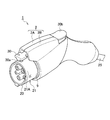
- FIG. 2 is an overall perspective view of the charging connector according to the embodiment of the present invention.
- FIG. 3 is an exploded perspective view of the charging connector according to the embodiment of the present invention.
- FIG. 4 is a cross-sectional view of a charging connector according to an embodiment of the present invention.
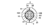
- 5 is a cross-sectional view taken along line VV in FIG. 6A is a cross-sectional view taken along the line VIA-VIA of FIG. 6B is a cross-sectional view taken along the line VIB-VIB of FIG.
- the charging connector 1 includes an outer case 2, a connector main body portion 20 accommodated in the outer case 2, a lock arm 30 disposed in the outer case 2, and a lock arm 30.
- the microswitch 31 that is turned on and off by the above and the seal member 40 are provided.
- the exterior case 2 is composed of two case division bodies 2A and 2B assembled to each other. Abutting surfaces 3 are provided on substantially the entire outer peripheral edge of each case divided body 2A, 2B.
- Each case divided body 2 ⁇ / b> A, 2 ⁇ / b> B has a lock arm housing chamber 4 and a connector housing chamber 5 inside, and the housing portions 4, 5 are partitioned by an internal partition wall 6.
- the front end surface of the internal partition wall 6 is a butt surface 7. Seal holding grooves 8 are formed at the locations of the butting surfaces 3 and 7 surrounding the connector housing chamber 5.
- the two case divided bodies 2A and 2B are assembled in a state where the butted surfaces 3 and 7 are butted against each other.
- the front end portion and the rear end portion of each case divided body 2A, 2B are formed in semicircular arc-shaped recesses 9A, 9B, respectively.
- the connector fitting portion protruding hole 9 is constituted by the concave portions 9 ⁇ / b> A and 9 ⁇ / b> B of the front end portion.
- the wire lead-out hole 10 is configured by the concave portions 10 ⁇ / b> A and 10 ⁇ / b> B at the rear end portion (see FIG. 5).
- arc-shaped concave portions 11A and 11B are formed in the internal partition wall 6 of each case division body 2A and 2B.
- the wire through-hole 11 is configured by the recesses 11 ⁇ / b> A and 11 ⁇ / b> B of both the internal partition walls 6 (see FIG. 6B).
- Seal holding grooves 8 are also formed on the inner surfaces of the recesses 9A, 9B, 10A, 10B, 11A, and 11B.
- the connector body 20 is housed in the connector housing 5.
- the connector body 20 includes a connector housing 21 and a plurality of terminals (not shown) accommodated in a terminal accommodation chamber (not shown) of the connector housing 21.
- a front portion of the connector housing 21 is a connector fitting portion 21A that is fitted into a power receiving inlet device (not shown).
- the connector fitting portion 21 ⁇ / b> A protrudes outside the outer case 2 from the connector fitting portion protruding hole 9.
- An electric wire W1 is connected to each terminal (not shown).
- the plurality of electric wires W1 drawn out from the connector housing 21 are accommodated in the protective tube 25 and led out of the outer case 2 through the electric wire drawing holes 10.
- the lock arm 30 and the micro switch 31 are accommodated in the lock arm accommodating chamber 4.
- the lock arm 30 is swingably supported by the outer case 2.
- the front side and the rear side of the lock arm 30 are exposed from the outer case 2.
- a lock claw 30 a is provided on the front side of the lock arm 30.
- the rear side of the lock arm 30 is a release operation unit 30b.
- the lock arm 30 is biased to the lock side by the spring force of the spring 32.
- the micro switch 31 has a case filled with an adhesive.
- the inside of the microswitch 31 is waterproofed by this filling adhesive.
- the micro switch 31 and one terminal (not shown) for fitting detection are connected by an internal electric wire W2. As a result, it is possible to detect whether or not the charging inlet device is fitted.
- the seal member 40 is made of a rubber material having excellent elasticity.
- the seal member 40 includes a case dividing surface sealing portion 41 disposed along the entire circumference of the abutting surfaces 3 and 7 of the case divided bodies 2A and 2B surrounding the connector main body portion 20 accommodated in the exterior case 2.
- the connector body sealing portion 42 disposed along the entire circumference of the connector fitting portion protruding hole 9, the wire sealing portion 43 disposed along the entire periphery of the wire lead-out hole 10, and the wire through-hole 11.
- the inner wire sealing portion 44 is disposed along the entire circumference, and these are integrally provided.
- the case division surface seal portion 41 is interposed between the two case division bodies 2A and 2B, and seals between the two case division bodies 2A and 2B by its own elastic compression.
- the connector main body seal portion 42 is interposed between the outer case 2 and the connector main body portion 20, and seals between the outer case 2 and the connector main body portion 20 by its own elastic compression.
- the wire seal portion 43 is interposed between the outer case 2 and the protective tube 25 of the electric wire W1, and between the outer case 2 and the protective tube 25 of the electric wire W1, its own elasticity. Sealed by compression.
- the inner wire seal portion 44 is interposed between both the inner partition walls 6 and the inner wire W2, and elastically compresses itself between the inner partition wall 6 and the inner wire W2. It is sealed by.
- the case splitting surface sealing portion 41 prevents water from entering through the gap between the case splitting bodies 2A and 2B.
- the connector main body seal portion 42 prevents water from entering the connector housing portion 5 from the connector fitting portion protruding hole 9 of the outer case 2.
- the electric wire sealing portion 43 prevents water from entering the connector housing chamber 5 from the electric wire through hole 10 of the outer case 2.
- the internal wire seal portion 44 prevents water from entering the connector housing chamber 5 from the wire through hole 11 in the exterior case 2.
- the seal member 40 is interposed between the two case divided bodies 2A and 2B, and is assembled between the outer case 2 and the connector main body 20 and between the outer case 2 and the electric wire W1.
- One part For this reason, component costs, assembly costs, and the like can be reduced compared to the case where a waterproof plug is attached to each terminal (not shown). Further, even if the number of terminals (not shown) increases, the cost does not increase. As described above, it is possible to provide a low-cost charging connector 1 having a structure for waterproofing a terminal (not shown).
- the seal member 40 integrally includes the internal electric wire seal portion 44, but the internal electric wire W2 may be sealed by a separate seal member.
- the plurality of electric wires W1 drawn out from the connector main body 20 are accommodated in the protective tube 25, and the gap between the protective tube 25 and the outer case 2 is sealed with the electric wire sealing portion 43, so that it is easy. Can be sealed.
- the plurality of electric wires W ⁇ b> 1 may not be accommodated in the protective tube 25, and in this case, the gap between the electric wires W ⁇ b> 1 and the outer case 2 is sealed with the electric wire seal portion 43.
- the seal member 40 is structured to seal the gap between the outer case 2 and the rocking lock arm 30, and the connector housing chamber 5 and the lock arm. Both the accommodation chambers 4 may be waterproofed.
Landscapes
- Engineering & Computer Science (AREA)
- Power Engineering (AREA)
- Transportation (AREA)
- Mechanical Engineering (AREA)
- Connector Housings Or Holding Contact Members (AREA)
Abstract
シール部材(40)が、外装ケース(2)内に収容されたコネクタ本体部(20)の箇所を囲む突き合わせ面(3、7)の全周に沿って配置されて2つのケース分割体(2A、2B)の突き合わせ面(3、7)間に介在されるケース分割面用シール部(41)と、コネクタ嵌合部突出穴(9)の全周に沿って配置されて外装ケース(2)とコネクタ本体部(20)間に介在されるコネクタ本体用シール部(42)と、電線引出穴(10)の全周に沿って配置されて外装ケース(2)と電線(W1)との間に介在される電線用シール部(43)とを一体に有する。
Description
本発明は、電気自動車やハイブリッド電気自動車等の車両に搭載されるバッテリーを充電する際に用いる充電コネクタに関する。
電気自動車(EV)やハイブリッド電気自動車(HEV)等の車両に搭載されたバッテリーを充電するために、充電コネクタが用いられる(特許文献1参照)。この種の充電コネクタの関連する例について、図1を参照しながら説明する。
充電コネクタ100は、図1に示すように、外装ケース110と、外装ケース110内に配置されたコネクタ本体部120と、外装ケース110内に配置されたロックアーム130とを備えている。
外装ケース110は、2つのケース分割体110A,110Bより形成されている。各ケース分割体110A,110Bは、互いに突き合わされる突き合わせ面111を有し、互いの突き合わせ面111同士が突き合わされている。外装ケース110の前端部には、コネクタ嵌合部露出穴112が設けられている。外装ケース110の後端側には、電線引出用穴113が設けられている。
コネクタ本体部120は、コネクタハウジング121と、コネクタハウジング121の端子収容室(図示せず)に収容された複数の端子(図示せず)とを有する。コネクタ本体部121の前方部は、コネクタ嵌合部突出穴112より外装ケース110外に突出している。この突出している箇所は、受電インレット装置(図示せず)に嵌合されるコネクタ嵌合部121Aである。
各端子(図示せず)には、電線Wがそれぞれ接続されている。コネクタハウジング121の電線配策箇所には、ゴム栓(図示せず)が装着されている。これにより、コネクタハウジング121内への浸水が防止されている。コネクタハウジング121より引き出された各電線Wは、電線引出穴113より外装ケース110外に導き出されている。
ロックアーム130は、外装ケース110に揺動自在に支持されている。ロックアーム130の前方側と後方側は、外装ケース110よりそれぞれ露出している。ロックアーム130は、充電インレット装置(図示せず)への嵌合過程ではアンロック位置に位置し、嵌合完了位置でロック位置に位置される。
上記関連する例では、外装ケース110内に水が浸入しても、浸入した水がコネクタハウジング121の端子(図示せず)位置まで入り込むのをゴム栓が阻止する。これにより、端子(図示せず)の防水が図られている。
ところで、ゴム栓は、高価で、且つ、端子の個数だけ必要であるため、部品コスト、組付け作業コスト等が高くつき、充電コネクタ100が高コストになる。端子の個数が多くなると、それにつれてコストアップになる。
本発明は、端子を防水する構造にあって、低コストな充電コネクタを提供することを目的とする。
実施形態に係る充電コネクタは、互いの突き合わせ面同士を突き合わせて組み付けされ、組み付け状態でコネクタ嵌合部突出穴と電線引出穴が開口される2つのケース分割体を含む外装ケースと、前記外装ケース内に収容されたコネクタ本体部であって、前記コネクタ嵌合部突出穴より前記外装ケース外に露出されたコネクタ嵌合部を有するコネクタ本体部と、前記外装ケース内に収容された前記コネクタ本体部の箇所を囲む前記突き合わせ面の全周に沿って配置され、前記2つのケース分割体の前記突き合わせ面間に介在されるケース分割面用シール部と、前記コネクタ嵌合部突出穴の全周に沿って配置され、前記外装ケースと前記コネクタ本体部間に介在されるコネクタ本体用シール部と、前記電線引出穴の全周に沿って配置され、前記外装ケースと前記コネクタ本体部より引き出されて前記電線引出穴より前記外装ケース外に導き出された電線との間に介在される電線用シール部とを一体に有するシール部材とを備える。
上記構成によれば、外装ケース内のコネクタ本体部への浸水がシール部材によって阻止されるため、コネクタ本体部内の端子を防水できる。シール部材は、2つのケース分割体の間に介在されると共に、外装ケースとコネクタ本体部の間、及び、外装ケースと電線との間に組み付けられる単一部品であるため、各端子に防水栓をそれぞれ装着する場合に較べて部品コストや組付コスト等が低コストで済む。又、端子の個数が多くなってもコストアップにならない。以上より、端子を防水する構造にあって、低コストな充電コネクタを提供できる。
以下、本発明の一実施形態を図面に基づいて説明する。
図2~図6Bは本発明の一実施形態を示す。図2~図4に示すように、充電コネクタ1は、外装ケース2と、外装ケース2内に収容されたコネクタ本体部20と、外装ケース2内に配置されたロックアーム30と、ロックアーム30によりオン・オフされるマイクロスイッチ31と、シール部材40とを備えている。
外装ケース2は、互いに組み付けされた2つのケース分割体2A,2Bより構成されている。各ケース分割体2A,2Bのほぼ全外周縁には、突き合わせ面3が設けられている。各ケース分割体2A,2Bには、ロックアーム収容室4とコネクタ収容室5を内部に有し、これら収容部4,5間は、内部仕切壁6によって仕切られている。この内部仕切壁6の先端面は、突き合わせ面7である。コネクタ収容室5を囲む突き合わせ面3,7の箇所には、シール保持溝8が形成されている。
2つのケース分割体2A,2Bは、互いの突き合わせ面3,7を突き合わせた状態で組み付けされる。各ケース分割体2A,2Bの前端部と後端部は、半円弧状の凹部9A,9Bにそれぞれ形成されている。外装ケース2の組み付け状態では、前端部の双方の凹部9A,9Bによってコネクタ嵌合部突出穴9が構成される。外装ケース2の組み付け状態では、後端部の双方の凹部10A,10Bによって電線引出穴10が構成される(図5参照)。又、各ケース分割体2A,2Bの内部仕切壁6には、円弧状の凹部11A,11B(図6A参照)が形成されている。外装ケース2の組み付け状態では、双方の内部仕切壁6の凹部11A,11Bによって電線貫通穴11が構成される(図6B参照)。各凹部9A,9B,10A,10B,11A,11Bの内面にも、シール保持溝8が形成されている。
コネクタ本体部20は、コネクタ収容室5内に収容されている。コネクタ本体部20は、コネクタハウジング21と、このコネクタハウジング21の端子収容室(図示せず)に収容された複数の端子(図示せず)とを有する。コネクタハウジング21の前方部は、受電インレット装置(図示せず)に嵌合されるコネクタ嵌合部21Aである。コネクタ嵌合部21Aは、コネクタ嵌合部突出穴9より外装ケース2外に突出している。
複数の端子(図示せず)は、電力供給用と嵌合検知用の二種類である。各端子(図示せず)には、電線W1がそれぞれ接続されている。コネクタハウジング21より引き出された複数の電線W1は、保護チューブ25内に収容されて電線引出穴10より外装ケース2外に導き出されている。
ロックアーム30とマイクロスイッチ31は、ロックアーム収容室4に収容されている。ロックアーム30は、外装ケース2に揺動自在に支持されている。ロックアーム30の前方側と後方側は、外装ケース2よりそれぞれ露出している。ロックアーム30の前方側には、ロック爪30aが設けられている。ロックアーム30の後方側は、解除操作部30bとされている。ロックアーム30は、バネ32のバネ力によってロック側に付勢されている。
マイクロスイッチ31は、そのケース内部が接着剤で充填されている。この充填接着剤によって、マイクロスイッチ31内は防水されている。マイクロスイッチ31と嵌合検知用の一端子(図示せず)の間は、内部電線W2によって接続されている。これにより、充電インレット装置との嵌合有無状態を検知できるようになっている。
シール部材40は、弾力性に優れたゴム材より形成されている。シール部材40は、外装ケース2内に収容されたコネクタ本体部20の箇所を囲むケース分割体2A,2Bの突き合わせ面3,7の全周に沿って配置されたケース分割面用シール部41と、コネクタ嵌合部突出穴9の全周に沿って配置されたコネクタ本体用シール部42と、電線引出穴10の全周に沿って配置された電線用シール部43と、電線貫通穴11の全周に沿って配置された内部電線用シール部44とからなり、これらが一体に設けられている。ケース分割面用シール部41は、2つのケース分割体2A,2B間に介在され、2つのケース分割体2A,2B間をそれ自身の弾性圧縮によって密閉している。コネクタ本体用シール部42は、図5に詳しく示すように、外装ケース2とコネクタ本体部20間に介在され、外装ケース2とコネクタ本体部20間をそれ自身の弾性圧縮によって密閉している。電線用シール部43は、図6Aに詳しく示すように、外装ケース2と電線W1の保護チューブ25との間に介在され、外装ケース2と電線W1の保護チューブ25との間をそれ自身の弾性圧縮によって密閉している。内部電線用シール部44は、図6Bに詳しく示すように、双方の内部仕切壁6と内部電線W2との間に介在され、内部仕切壁6と内部電線W2との間をそれ自身の弾性圧縮によって密閉している。
上記構成の充電コネクタ1では、ケース分割体2A,2B間の隙間からの浸水をケース分割面用シール部41で防止する。また、外装ケース2のコネクタ嵌合部突出穴9からコネクタ収容室5への浸水をコネクタ本体用シール部42で防止する。また、外装ケース2の電線貫通穴10からコネクタ収容室5への浸水を電線用シール部43で防止する。また、外装ケース2内の電線貫通穴11からコネクタ収容室5への浸水を内部電線用シール部44で防止する。このように、外装ケース2内のコネクタ収容室5、つまり、コネクタ本体部20への浸水がシール部材40によって阻止されるため、コネクタ本体部20内の端子(図示せず)を防水できる。ここで、シール部材40は、2つのケース分割体2A,2Bの間に介在されると共に、外装ケース2とコネクタ本体部20の間、及び、外装ケース2と電線W1との間に組み付けられる単一部品である。このため、各端子(図示せず)毎に防水栓をそれぞれ装着する場合に較べて部品コストや組付コスト等が低コストで済む。又、端子(図示せず)の個数が多くなってもコストアップにならない。以上より、端子(図示せず)を防水する構造にあって、低コストな充電コネクタ1を提供できる。
本実施形態では、シール部材40は、内部電線用シール部44をも一体に有するが、内部電線W2については別個のシール部材によってシールするようにしても良い。
本実施形態では、コネクタ本体部20より引き出された複数の電線W1は保護チューブ25内に収容され、保護チューブ25と外装ケース2間の隙間を電線用シール部43で密閉しているため、容易に密閉できる。複数の電線W1は、保護チューブ25に収容しなくても良く、この場合には電線W1と外装ケース2間の隙間を電線用シール部43で密閉する。
本実施形態では、外装ケース2内のコネクタ収容室5のみを防水したが、シール部材40を外装ケース2と揺動するロックアーム30との隙間を密閉する構造とし、コネクタ収容室5とロックアーム収容室4の双方を防水するようにしても良い。
このように、本発明は、ここでは記載していない様々な実施の形態などを含むことは勿論である。したがって、本発明の技術的範囲は、上述の説明から妥当な特許請求の範囲に係る発明特定事項によってのみ定められる。
特願2012-235540号(出願日:2012年10月25日)の全内容は、ここに援用される。
Claims (1)
- 互いの突き合わせ面同士を突き合わせて組み付けされ、組み付け状態でコネクタ嵌合部突出穴と電線引出穴が開口される2つのケース分割体を含む外装ケースと、
前記外装ケース内に収容されたコネクタ本体部であって、前記コネクタ嵌合部突出穴より前記外装ケース外に露出されたコネクタ嵌合部を有するコネクタ本体部と、
前記外装ケース内に収容された前記コネクタ本体部の箇所を囲む前記突き合わせ面の全周に沿って配置され、前記2つのケース分割体の前記突き合わせ面間に介在されるケース分割面用シール部と、前記コネクタ嵌合部突出穴の全周に沿って配置され、前記外装ケースと前記コネクタ本体部間に介在されるコネクタ本体用シール部と、前記電線引出穴の全周に沿って配置され、前記外装ケースと前記コネクタ本体部より引き出されて前記電線引出穴より前記外装ケース外に導き出された電線との間に介在される電線用シール部とを一体に有するシール部材と、
を備えた充電コネクタ。
Priority Applications (3)
| Application Number | Priority Date | Filing Date | Title |
|---|---|---|---|
| CN201380055430.7A CN104756324B (zh) | 2012-10-25 | 2013-10-09 | 充电连接器 |
| US14/435,771 US20150295344A1 (en) | 2012-10-25 | 2013-10-09 | Charging connector |
| EP13849488.5A EP2913899B1 (en) | 2012-10-25 | 2013-10-09 | Charging connector |
Applications Claiming Priority (2)
| Application Number | Priority Date | Filing Date | Title |
|---|---|---|---|
| JP2012-235540 | 2012-10-25 | ||
| JP2012235540A JP2014086338A (ja) | 2012-10-25 | 2012-10-25 | 充電コネクタ |
Publications (1)
| Publication Number | Publication Date |
|---|---|
| WO2014065120A1 true WO2014065120A1 (ja) | 2014-05-01 |
Family
ID=50544500
Family Applications (1)
| Application Number | Title | Priority Date | Filing Date |
|---|---|---|---|
| PCT/JP2013/077459 Ceased WO2014065120A1 (ja) | 2012-10-25 | 2013-10-09 | 充電コネクタ |
Country Status (5)
| Country | Link |
|---|---|
| US (1) | US20150295344A1 (ja) |
| EP (1) | EP2913899B1 (ja) |
| JP (1) | JP2014086338A (ja) |
| CN (1) | CN104756324B (ja) |
| WO (1) | WO2014065120A1 (ja) |
Families Citing this family (28)
| Publication number | Priority date | Publication date | Assignee | Title |
|---|---|---|---|---|
| JP5939927B2 (ja) * | 2012-08-06 | 2016-06-22 | 矢崎総業株式会社 | 充電コネクタ |
| CN105103385B (zh) * | 2013-03-28 | 2017-02-22 | 矢崎总业株式会社 | 充电连接器 |
| US10649497B2 (en) * | 2014-07-23 | 2020-05-12 | Apple Inc. | Adaptive processes for improving integrity of surfaces |
| WO2016014047A1 (en) | 2014-07-23 | 2016-01-28 | Apple Inc. | Adaptive processes for improving integrity of surfaces |
| TWD169202S (zh) * | 2014-09-22 | 2015-07-21 | 龍咬實業股份有限公司 | 充電槍 |
| DE102015101265A1 (de) * | 2015-01-29 | 2016-08-04 | Phoenix Contact E-Mobility Gmbh | Steckverbinder |
| PL3285328T3 (pl) * | 2015-10-02 | 2021-01-25 | Lg Chem, Ltd. | Moduł baterii o ulepszonych właściwościach uszczelnienia kanału chłodzącego |
| US10118496B2 (en) * | 2016-02-04 | 2018-11-06 | Dragon Bite Industrial Co., Ltd. | Waterproofing members integrally formed with elements of a charging coupler |
| CN105811151A (zh) * | 2016-05-18 | 2016-07-27 | 江苏健龙电器有限公司 | 一种电动车用直流电充电插头 |
| CN105811152A (zh) * | 2016-05-18 | 2016-07-27 | 江苏健龙电器有限公司 | 一种电动车用交流电充电插头 |
| US10014615B2 (en) * | 2016-09-19 | 2018-07-03 | Lear Corporation | Connector assemblies for vehicle charging |
| CN108583315B (zh) * | 2018-04-03 | 2020-05-22 | 浙江吉利汽车研究院有限公司 | 一种汽车充电插座的安装结构 |
| DE102018208421A1 (de) * | 2018-05-28 | 2019-11-28 | Bayerische Motoren Werke Aktiengesellschaft | Fixierungshülse zur festen Fixierung eines Steckers an einer Buchse und Injektorbaugruppe |
| CN108879267B (zh) * | 2018-06-29 | 2023-12-19 | 东莞市何谐新能源科技有限公司 | 一种交流充电连接器 |
| USD902866S1 (en) * | 2018-08-01 | 2020-11-24 | Phoenix Contact E-Mobility Gmbh | Cable feed-through for electric vehicles |
| CN114552277A (zh) | 2020-11-24 | 2022-05-27 | 台达电子工业股份有限公司 | 充电枪 |
| USD988991S1 (en) * | 2021-05-10 | 2023-06-13 | Ten Pao International Limited | Electric vehicle gun charger |
| NO347343B1 (en) * | 2021-12-23 | 2023-09-25 | Defa As | A connector assembly |
| WO2023148245A1 (de) * | 2022-02-03 | 2023-08-10 | Robert Bosch Gmbh | Verbinder für ein versorgungskabel mit verbesserter dichtung |
| US11998649B2 (en) | 2022-02-24 | 2024-06-04 | Jvis-Usa, Llc | Antimicrobial, push button switch assembly for use at a self-service, dispensing or charging station |
| USD1018469S1 (en) * | 2022-05-17 | 2024-03-19 | Christopher Eckhard Maiwald | Charging adapter |
| USD1040110S1 (en) * | 2023-06-01 | 2024-08-27 | Shenzhen Yongchuangcheng Technology Co., Ltd. | Charging connector |
| USD1095446S1 (en) * | 2023-06-08 | 2025-09-30 | Jianrong Liu | Charging adapter |
| USD1079615S1 (en) * | 2023-07-31 | 2025-06-17 | Shenzhen Qunchuang Electronics Co., Ltd. | Charging device for an electric vehicle |
| USD1046773S1 (en) * | 2023-09-12 | 2024-10-15 | Shenzhen Yongchuangcheng Technology Co., Ltd. | Charging adapter |
| USD1040089S1 (en) * | 2023-09-12 | 2024-08-27 | Shenzhen Yongchuangcheng Technology Co., Ltd. | Charging connector |
| USD1049043S1 (en) * | 2023-12-14 | 2024-10-29 | Shenzhen Yongchuangcheng Technology Co., Ltd. | Adapter |
| SE2450564A1 (en) * | 2024-05-24 | 2025-11-25 | Charge Amps Ab | Socket for an evse |
Citations (6)
| Publication number | Priority date | Publication date | Assignee | Title |
|---|---|---|---|---|
| JPH06333633A (ja) * | 1993-05-25 | 1994-12-02 | Sumitomo Wiring Syst Ltd | コネクタ |
| JP2010182471A (ja) | 2009-02-04 | 2010-08-19 | Yazaki Corp | コネクタ |
| JP2012146652A (ja) * | 2011-01-06 | 2012-08-02 | General Cable Technologies Corp | プラグインハイブリッド電気自動車充電用の層状多ポリマー高アンペア数オーバーモールドコネクタアセンブリ |
| JP2012230850A (ja) * | 2011-04-27 | 2012-11-22 | Auto Network Gijutsu Kenkyusho:Kk | 充電用コネクタ |
| JP2013097898A (ja) * | 2011-10-28 | 2013-05-20 | Sumitomo Wiring Syst Ltd | シール部材 |
| JP2013140699A (ja) * | 2011-12-29 | 2013-07-18 | General Cable Technologies Corp | プラグインハイブリッド電気自動車充電用の層状多ポリマー高アンペア数オーバーモールドコネクタアセンブリ |
Family Cites Families (28)
| Publication number | Priority date | Publication date | Assignee | Title |
|---|---|---|---|---|
| US4111234A (en) * | 1976-11-11 | 1978-09-05 | Wells James W | Repair device for pipes |
| DE19544942C2 (de) * | 1994-12-01 | 2001-12-06 | Yazaki Corp | Verbindungsvorrichtung mit einem Spannungszufuhrsteckverbinder und einem Spannungsaufnahmesteckverbinder und Verfahren zum Verbinden/Trennen einer Spannungszufuhreinrichtung |
| US5934938A (en) * | 1996-08-20 | 1999-08-10 | Chrysler Corporation | Split seal retainer for an electrical connector |
| JPH10339597A (ja) * | 1997-04-08 | 1998-12-22 | Denso Corp | 熱交換器のシール構造 |
| US7044760B2 (en) * | 1997-07-30 | 2006-05-16 | Thomas & Betts International, Inc. | Separable electrical connector assembly |
| JP2002324621A (ja) * | 2001-04-24 | 2002-11-08 | Yazaki Corp | コネクタ |
| JP4092926B2 (ja) * | 2002-02-27 | 2008-05-28 | 松下電工株式会社 | コードコネクタ |
| US7388152B2 (en) * | 2005-08-29 | 2008-06-17 | Ocean Design, Inc. | Cable seal assembly and method |
| CA2663988C (en) * | 2008-04-24 | 2012-10-23 | Baker Hughes Incorporated | Pothead for use in highly severe conditions |
| JP5238803B2 (ja) * | 2008-04-28 | 2013-07-17 | 日本特殊陶業株式会社 | スパークプラグ |
| CN101740947B (zh) * | 2008-11-25 | 2012-08-01 | 比亚迪股份有限公司 | 用于可电力驱动的车辆的充电装置 |
| JP5482295B2 (ja) * | 2010-03-01 | 2014-05-07 | 住友電装株式会社 | 充電用コネクタ |
| JP5447962B2 (ja) * | 2010-02-19 | 2014-03-19 | 住友電装株式会社 | 充電用コネクタ |
| JP2011198566A (ja) * | 2010-03-18 | 2011-10-06 | Sumitomo Wiring Syst Ltd | 充電用コネクタ |
| WO2011162926A2 (en) * | 2010-06-21 | 2011-12-29 | 3M Innovative Properties Company | Sealing member for an enclosure |
| JP5471890B2 (ja) * | 2010-06-28 | 2014-04-16 | 住友電装株式会社 | 充電用コネクタ |
| US7878866B1 (en) * | 2010-07-02 | 2011-02-01 | Lear Corporation | Connector assembly for vehicle charging |
| JP5197699B2 (ja) * | 2010-09-09 | 2013-05-15 | 住友電装株式会社 | 充電用コネクタ |
| US8568155B2 (en) * | 2010-12-30 | 2013-10-29 | General Cable Technologies Corporation | Laminous multi-polymeric high amperage over-molded connector assembly for plug-in hybrid electric vehicle charging |
| US8562365B2 (en) * | 2010-12-30 | 2013-10-22 | General Cable Technologies Corporation | Laminous multi-polymeric high amperage over-molded connector assembly for plug-in hybrid electric vehicle charging |
| JP5640220B2 (ja) * | 2011-01-24 | 2014-12-17 | 株式会社豊田自動織機 | 車両充電用ケーブルのコンセントプラグ |
| DE102011002024A1 (de) * | 2011-04-13 | 2012-10-18 | Tyco Electronics Amp Gmbh | Ladestecker mit berührungsloser Schaltvorrichtung |
| CN202068024U (zh) * | 2011-04-26 | 2011-12-07 | 乐清市荣盛引进电器有限公司 | 一种电动汽车充电连接装置 |
| US8834202B2 (en) * | 2011-06-13 | 2014-09-16 | Lear Corporation | Connector assembly for vehicle charging |
| CN202178439U (zh) * | 2011-08-29 | 2012-03-28 | 江苏西比亚新能源科技有限公司 | 一种快速充电的电动汽车连接器 |
| US9139097B2 (en) * | 2012-01-05 | 2015-09-22 | Remy Technologies, Llc | Safety cover with integrated magnet for reed switch |
| DE102014003565A1 (de) * | 2013-03-19 | 2014-09-25 | Sumitomo Wiring Systems, Ltd. | Fahrzeugseitiger Verbinder und Verfahren zum Zusammenbauen desselben |
| JP6070519B2 (ja) * | 2013-11-25 | 2017-02-01 | 住友電装株式会社 | 車両側コネクタ |
-
2012
- 2012-10-25 JP JP2012235540A patent/JP2014086338A/ja not_active Abandoned
-
2013
- 2013-10-09 US US14/435,771 patent/US20150295344A1/en active Granted
- 2013-10-09 EP EP13849488.5A patent/EP2913899B1/en active Active
- 2013-10-09 CN CN201380055430.7A patent/CN104756324B/zh active Active
- 2013-10-09 WO PCT/JP2013/077459 patent/WO2014065120A1/ja not_active Ceased
Patent Citations (6)
| Publication number | Priority date | Publication date | Assignee | Title |
|---|---|---|---|---|
| JPH06333633A (ja) * | 1993-05-25 | 1994-12-02 | Sumitomo Wiring Syst Ltd | コネクタ |
| JP2010182471A (ja) | 2009-02-04 | 2010-08-19 | Yazaki Corp | コネクタ |
| JP2012146652A (ja) * | 2011-01-06 | 2012-08-02 | General Cable Technologies Corp | プラグインハイブリッド電気自動車充電用の層状多ポリマー高アンペア数オーバーモールドコネクタアセンブリ |
| JP2012230850A (ja) * | 2011-04-27 | 2012-11-22 | Auto Network Gijutsu Kenkyusho:Kk | 充電用コネクタ |
| JP2013097898A (ja) * | 2011-10-28 | 2013-05-20 | Sumitomo Wiring Syst Ltd | シール部材 |
| JP2013140699A (ja) * | 2011-12-29 | 2013-07-18 | General Cable Technologies Corp | プラグインハイブリッド電気自動車充電用の層状多ポリマー高アンペア数オーバーモールドコネクタアセンブリ |
Non-Patent Citations (1)
| Title |
|---|
| See also references of EP2913899A4 |
Also Published As
| Publication number | Publication date |
|---|---|
| JP2014086338A (ja) | 2014-05-12 |
| EP2913899A4 (en) | 2016-04-13 |
| EP2913899A1 (en) | 2015-09-02 |
| CN104756324A (zh) | 2015-07-01 |
| EP2913899B1 (en) | 2017-03-01 |
| US20150295344A1 (en) | 2015-10-15 |
| CN104756324B (zh) | 2017-09-01 |
Similar Documents
| Publication | Publication Date | Title |
|---|---|---|
| WO2014065120A1 (ja) | 充電コネクタ | |
| JP5757219B2 (ja) | シール部材 | |
| US7828591B2 (en) | Connector for a device | |
| JP5854302B2 (ja) | 車両側コネクタ | |
| CN100388598C (zh) | 将电线连接到装置屏蔽壳的连接结构 | |
| JP5352412B2 (ja) | 電動工具 | |
| JP5184619B2 (ja) | コネクタ | |
| JP2019192482A (ja) | 充電コネクタ | |
| JP2014038793A (ja) | コネクタ | |
| JP2014086349A (ja) | コネクタ | |
| CN104685727A (zh) | 充电连接器 | |
| WO2013051528A1 (ja) | コネクタ | |
| JP2018063814A (ja) | 電源接続システム | |
| JP5809083B2 (ja) | 防水コネクタ | |
| JP5939954B2 (ja) | 端子用スペーサ | |
| JP2015122249A (ja) | コネクタ | |
| WO2022255476A1 (ja) | コネクタ | |
| CN102195201B (zh) | 插头 | |
| JP5840175B2 (ja) | コネクタ、及びコネクタユニット | |
| JP5685453B2 (ja) | コネクタ用フィルタ部材、コネクタ組立体、コネクタ組立体の組立方法 | |
| JP2019083184A (ja) | コネクタ | |
| KR101524171B1 (ko) | 전기적 소자의 시일 구조 | |
| JP6169385B2 (ja) | 充電コネクタ | |
| JP6708029B2 (ja) | コネクタ | |
| KR20130038442A (ko) | 차량용 고전압 커넥터 |
Legal Events
| Date | Code | Title | Description |
|---|---|---|---|
| 121 | Ep: the epo has been informed by wipo that ep was designated in this application |
Ref document number: 13849488 Country of ref document: EP Kind code of ref document: A1 |
|
| WWE | Wipo information: entry into national phase |
Ref document number: 14435771 Country of ref document: US |
|
| NENP | Non-entry into the national phase |
Ref country code: DE |
|
| REEP | Request for entry into the european phase |
Ref document number: 2013849488 Country of ref document: EP |
|
| WWE | Wipo information: entry into national phase |
Ref document number: 2013849488 Country of ref document: EP |