WO2014065277A1 - 自動分析装置 - Google Patents
自動分析装置 Download PDFInfo
- Publication number
- WO2014065277A1 WO2014065277A1 PCT/JP2013/078576 JP2013078576W WO2014065277A1 WO 2014065277 A1 WO2014065277 A1 WO 2014065277A1 JP 2013078576 W JP2013078576 W JP 2013078576W WO 2014065277 A1 WO2014065277 A1 WO 2014065277A1
- Authority
- WO
- WIPO (PCT)
- Prior art keywords
- work
- schedule
- automatic analyzer
- unit
- user
- Prior art date
- Legal status (The legal status is an assumption and is not a legal conclusion. Google has not performed a legal analysis and makes no representation as to the accuracy of the status listed.)
- Ceased
Links
Images

Classifications
-
- G—PHYSICS
- G06—COMPUTING OR CALCULATING; COUNTING
- G06Q—INFORMATION AND COMMUNICATION TECHNOLOGY [ICT] SPECIALLY ADAPTED FOR ADMINISTRATIVE, COMMERCIAL, FINANCIAL, MANAGERIAL OR SUPERVISORY PURPOSES; SYSTEMS OR METHODS SPECIALLY ADAPTED FOR ADMINISTRATIVE, COMMERCIAL, FINANCIAL, MANAGERIAL OR SUPERVISORY PURPOSES, NOT OTHERWISE PROVIDED FOR
- G06Q10/00—Administration; Management
- G06Q10/06—Resources, workflows, human or project management; Enterprise or organisation planning; Enterprise or organisation modelling
- G06Q10/063—Operations research, analysis or management
- G06Q10/0631—Resource planning, allocation, distributing or scheduling for enterprises or organisations
- G06Q10/06311—Scheduling, planning or task assignment for a person or group
- G06Q10/063114—Status monitoring or status determination for a person or group
-
- G—PHYSICS
- G01—MEASURING; TESTING
- G01N—INVESTIGATING OR ANALYSING MATERIALS BY DETERMINING THEIR CHEMICAL OR PHYSICAL PROPERTIES
- G01N35/00—Automatic analysis not limited to methods or materials provided for in any single one of groups G01N1/00 - G01N33/00; Handling materials therefor
- G01N35/00584—Control arrangements for automatic analysers
- G01N35/0092—Scheduling
-
- G—PHYSICS
- G06—COMPUTING OR CALCULATING; COUNTING
- G06Q—INFORMATION AND COMMUNICATION TECHNOLOGY [ICT] SPECIALLY ADAPTED FOR ADMINISTRATIVE, COMMERCIAL, FINANCIAL, MANAGERIAL OR SUPERVISORY PURPOSES; SYSTEMS OR METHODS SPECIALLY ADAPTED FOR ADMINISTRATIVE, COMMERCIAL, FINANCIAL, MANAGERIAL OR SUPERVISORY PURPOSES, NOT OTHERWISE PROVIDED FOR
- G06Q10/00—Administration; Management
- G06Q10/06—Resources, workflows, human or project management; Enterprise or organisation planning; Enterprise or organisation modelling
- G06Q10/063—Operations research, analysis or management
- G06Q10/0631—Resource planning, allocation, distributing or scheduling for enterprises or organisations
- G06Q10/06311—Scheduling, planning or task assignment for a person or group
-
- G—PHYSICS
- G16—INFORMATION AND COMMUNICATION TECHNOLOGY [ICT] SPECIALLY ADAPTED FOR SPECIFIC APPLICATION FIELDS
- G16H—HEALTHCARE INFORMATICS, i.e. INFORMATION AND COMMUNICATION TECHNOLOGY [ICT] SPECIALLY ADAPTED FOR THE HANDLING OR PROCESSING OF MEDICAL OR HEALTHCARE DATA
- G16H40/00—ICT specially adapted for the management or administration of healthcare resources or facilities; ICT specially adapted for the management or operation of medical equipment or devices
- G16H40/20—ICT specially adapted for the management or administration of healthcare resources or facilities; ICT specially adapted for the management or operation of medical equipment or devices for the management or administration of healthcare resources or facilities, e.g. managing hospital staff or surgery rooms
-
- G—PHYSICS
- G16—INFORMATION AND COMMUNICATION TECHNOLOGY [ICT] SPECIALLY ADAPTED FOR SPECIFIC APPLICATION FIELDS
- G16H—HEALTHCARE INFORMATICS, i.e. INFORMATION AND COMMUNICATION TECHNOLOGY [ICT] SPECIALLY ADAPTED FOR THE HANDLING OR PROCESSING OF MEDICAL OR HEALTHCARE DATA
- G16H40/00—ICT specially adapted for the management or administration of healthcare resources or facilities; ICT specially adapted for the management or operation of medical equipment or devices
- G16H40/40—ICT specially adapted for the management or administration of healthcare resources or facilities; ICT specially adapted for the management or operation of medical equipment or devices for the management of medical equipment or devices, e.g. scheduling maintenance or upgrades
-
- G—PHYSICS
- G01—MEASURING; TESTING
- G01N—INVESTIGATING OR ANALYSING MATERIALS BY DETERMINING THEIR CHEMICAL OR PHYSICAL PROPERTIES
- G01N35/00—Automatic analysis not limited to methods or materials provided for in any single one of groups G01N1/00 - G01N33/00; Handling materials therefor
- G01N2035/00178—Special arrangements of analysers
- G01N2035/00326—Analysers with modular structure
-
- G—PHYSICS
- G01—MEASURING; TESTING
- G01N—INVESTIGATING OR ANALYSING MATERIALS BY DETERMINING THEIR CHEMICAL OR PHYSICAL PROPERTIES
- G01N35/00—Automatic analysis not limited to methods or materials provided for in any single one of groups G01N1/00 - G01N33/00; Handling materials therefor
- G01N35/02—Automatic analysis not limited to methods or materials provided for in any single one of groups G01N1/00 - G01N33/00; Handling materials therefor using a plurality of sample containers moved by a conveyor system past one or more treatment or analysis stations
- G01N35/04—Details of the conveyor system
- G01N2035/0439—Rotary sample carriers, i.e. carousels
- G01N2035/0453—Multiple carousels working in parallel
-
- G—PHYSICS
- G01—MEASURING; TESTING
- G01N—INVESTIGATING OR ANALYSING MATERIALS BY DETERMINING THEIR CHEMICAL OR PHYSICAL PROPERTIES
- G01N35/00—Automatic analysis not limited to methods or materials provided for in any single one of groups G01N1/00 - G01N33/00; Handling materials therefor
- G01N35/02—Automatic analysis not limited to methods or materials provided for in any single one of groups G01N1/00 - G01N33/00; Handling materials therefor using a plurality of sample containers moved by a conveyor system past one or more treatment or analysis stations
- G01N35/025—Automatic analysis not limited to methods or materials provided for in any single one of groups G01N1/00 - G01N33/00; Handling materials therefor using a plurality of sample containers moved by a conveyor system past one or more treatment or analysis stations having a carousel or turntable for reaction cells or cuvettes
Definitions
- the present invention relates to an automatic analyzer that measures biological samples such as blood and urine, and more particularly to an automatic analyzer having a user interface for efficiently planning and managing a user's work schedule in the automatic analyzer.
- an automatic analyzer that analyzes using biological samples such as blood and urine and reagents, at the start of analysis or during the analysis process, every predetermined time determined according to each reagent, or as needed during the analysis process, It is necessary to carry out calibration which is a calibration curve calibration operation and accuracy control for keeping an automatic analyzer in a good state.
- Calibration is performed using a standard solution of a concentration determined according to each item. Calibration and quality control have an expiration date corresponding to each analysis item. Therefore, after the expiration date, recalibration and reprecision control must be performed. In addition, in each analysis item, it is necessary to use up the reagent of one reagent bottle and to carry out recalibration and requality control also when using a reagent of a new reagent bottle.
- the device automatically detects a predetermined time, an expiration date, switching to a new reagent bottle, etc. determined according to the above-mentioned respective reagents, and the user needs to carry out calibration and accuracy management. What notifies that is known (for example, refer to patent documents 1).
- Patent Document 1 The function described in Patent Document 1 is an effective technique that indicates whether calibration or quality control sample analysis is required immediately at a certain point for each analysis item, but the user is not required to carry out any factor for any factor. What we can know is when it is approaching. Heretofore, there has been no means to predict the need for calibration or quality control for a fixed period in the future, and to make an analysis schedule. For this reason, it has been difficult for the user to systematically prepare and analyze a standard sample for calibration, a control sample for quality control, and a reagent for analyzing these.
- a maintenance function for maintaining and managing the device has been increased accordingly.
- a maintenance function for example, it is necessary to replace the light source of the photometer incorporated in the automatic analyzer at predetermined time intervals.
- Such a maintenance function also needs to be regularly executed, and the conventional automatic analyzer also has a function to control the time limit.
- the conventional automatic analyzer Similar to the calibration and accuracy control described above, it is difficult for the user to know whether or not it is necessary to conduct maintenance regularly when it is imminent.
- an object of the present invention is to provide an automatic analyzer capable of predicting in advance the work to be performed by the user within the assigned time, efficiently planning the work according to the work schedule of the user, and performing without omission. It is to do.
- the present invention provides an input unit for inputting a work schedule of a user who uses an apparatus, a planning unit for planning in advance a work event required to use the apparatus, and the input unit
- a schedule creation unit for creating a time-sequential work schedule as a list of work to be performed by the user within the assigned time from the work schedule input from the work event and the work event planned by the planning unit;
- a display unit for displaying the created work schedule.
- the present invention it is possible to foresee in advance the work to be performed by the user within the assigned time, efficiently plan the work in accordance with the work schedule of the user, and perform without omission.
- FIG. 1 is a system configuration diagram showing an entire configuration of an automatic analyzer according to an embodiment of the present invention. It is a block diagram which shows the structure of operation part PC used for the automatic analyzer by one Embodiment of this invention. It is explanatory drawing of an example of the work schedule screen in the automatic analyzer by one Embodiment of this invention. It is explanatory drawing of an example of the operation
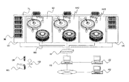
- FIG. 1 is a system configuration diagram showing an entire configuration of an automatic analyzer according to an embodiment of the present invention.
- the automatic analyzer includes, for example, three analyzers AA1, AA2, and AA3 arranged in series.
- the number of analysis units is not limited to three, and may be plural or singular.
- a transport line TRL for transporting a sample rack is provided adjacent to each analysis unit AA1, AA2, AA3.
- the sample loading unit SAI is provided on one end side of the analysis units AA1, AA2, AA3 arranged in series, and the sample storage unit SAO is provided on the other end.
- the user USR loads the sample SMP, which is the target of calibration measurement, quality control sample measurement, and patient sample measurement, in the sample rack SML.
- a plurality of samples can be mounted on the sample rack SML.
- the sample rack SML loaded with the sample is placed in the sample insertion unit SAI.
- the installed sample racks SML are sequentially carried into the transport line 305, and transported to the analysis units AA1, AA2, and AA3 that analyze the samples.
- the analysis units AA1, AA2, and AA3 respectively recognize the sample rack SML and the sample SMP, and perform analysis necessary for the sample SMP.
- Each of the analysis units AA1, AA2, and AA3 includes a reagent disk RED that stores a plurality of reagents REG used to perform the analysis.
- the reagent REG required for analysis is placed on the reagent disc RED prior to analysis by the user.
- the sample rack SML for which the necessary analysis has been performed is transported to the sample storage unit SAO.
- the sample loading unit SAI, the analysis units AA1, AA2, and AA3, and the sample storage unit SAO are each connected to the operation unit PC100 of the automatic analyzer via the hub HB with a network cable.
- the operation unit PC 100 is connected to the upper host system USY via a network.
- the user makes an analysis request (measurement request) for each sample from the host system USY or the operation unit PC 100, mounts the sample to be analyzed in the sample rack SML, and installs the sample in the sample loading unit SAI.
- the information requested for analysis is transmitted to the analysis units AA1, AA2 and AA3 via the network, and the analysis results of the analysis units AA1, AA2 and AA3 are transmitted to the operation unit PC100 and the upper host system USY.
- the operation unit PC100 is connected to the remote system RSY via a public line.
- the remote system RSY stores information such as analysis parameters which is analysis condition information using a reagent used in the automatic analyzer, and distributes analysis parameters in response to a request from the operation unit PC 100.
- the distributed analysis parameters are stored in the operation unit PC100, and transmitted to the analysis units AA1, AA2, and AA3 at the time of analysis of the sample.
- the operation unit PC100 is in charge of the work schedule information inputted by the upper host system USY which is the upper system of the operation unit PC100 or the automatic analysis apparatus or the remote system RSY and the work event information of the device managed by the operation unit PC100. Create work schedule information for each person.
- the user can confirm the work that he / she must perform on the work schedule screen displayed on the operation unit PC 100, and can make an efficient work plan in accordance with the work schedule.
- the work schedule management unit is provided on the upper host system or remote system that is the upper system according to the user's usage pattern, and the information is transmitted / received to / from the operation unit PC and analysis unit via the network good.
- FIG. 2 is a block diagram showing the configuration of the operation unit PC used in the automatic analyzer according to one embodiment of the present invention.
- the operation unit PC 100 mainly includes a control unit 110, an input unit 120, a display unit 130, and a storage unit 140.
- the input unit 120 includes a keyboard and a mouse.
- the display of the button displayed on the display unit 130 can be pressed down (clicked with the mouse), or numbers and characters can be input to the input frame displayed on the display unit 130 from the keyboard.
- a GUI Graphic User Interface
- the control unit 110 includes a planning unit 112, a schedule creation unit 113, a notification unit 114, a reservation unit 116, and a determination unit 118. These functions and operations will be described later.
- the storage unit 140 stores the work schedule information and the work event information described above.
- the planning unit 112 uses this information to plan a work schedule.
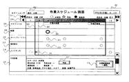
- FIG. 3 is an explanatory diagram of an example of a work schedule screen in the automatic analyzer according to one embodiment of the present invention.
- the work schedule screen 301 is displayed on the display unit 130 of FIG.
- the work schedule screen 301 displays, as a time schedule, a list of work that the user who has logged in to the operation unit PC 100 has to perform within the assigned time.
- the initial display of the work schedule screen 301 is optimized for the work user by centering the work schedule of the login user in the relevant time zone.
- the charge back and forth movement button 303 is a button for displaying the work schedule of the person in charge before and the person in charge after the login user.
- the time back and forth movement button 304 is a button for scrolling the display of the work schedule on an hourly basis.
- the schedule display area 305 displays the schedule of the hospital or the examination room.
- the reagent operation display area 308 displays a reagent operation event 309 such as reagent addition accompanying reagent shortage.
- the calibration operation display area 310 displays a calibration operation event 311 such as calibration measurement accompanying reagent addition or timeout.
- the quality control work display area 312 displays a quality control work event 313 such as quality control measurement associated with reagent addition and time-out.
- the maintenance operation display area 314 displays a maintenance operation event 315 such as maintenance execution accompanying a timeout or parts replacement. It is preferable to improve the visibility of each work event by changing the mark depending on the work situation.
- the time slot 306 for the logged-in user and the current time line 307 are displayed.
- the person in charge can easily confirm the work to be performed within the assigned time, and it is possible to confirm at what timing the work will occur with respect to the schedule of the hospital or examination room, efficiently It can be judged whether it can work.
- the type of work event displayed on this screen As the type of work event displayed on this screen, as shown in the screen example, it is best to set it as the work related to the most important reagent for guaranteeing the performance as an automatic analyzer, calibration, accuracy control, and maintenance, It is desirable to be customizable according to the purpose of the user who uses it.
- the reagent operation event 309, the calibration operation event 311, the quality control operation event 313, etc. will occur during the inspection in the afternoon, and know that the morning inspection may be interrupted.
- the maintenance work event 315 displays the dotted circle and the solid circle connected by an arrow, and represents the work carried forward by the login user because the person in charge has not performed the work.
- the work detail display area 316 displays the details of the work event selected on the screen.
- the reagent operation event 309 is in a state of being selected.
- the reagent operation event 309 in the reagent operation display area 308 is surrounded by a thick circle, which indicates, for example, a selected state.
- the color of the circle mark of the selected event or the like is changed to indicate that it is selected.
- the work detail area 316 displays the work execution status, the occurrence time, the reservation time, the execution time, the implementer and the work content.
- a work reservation button 317 is provided for reserving work at a convenient time in advance when the occurrence time is inconvenient on the schedule.
- the work execution screen transition button 318 the screen can be directly transitioned to each work execution screen for performing the work, and the work can be performed promptly.
- the user can confirm the work to be performed within the assigned time, and can make an efficient work plan.
- the work schedule screen 301 when the user logs out from the operation unit PC 100, the user can check whether there is nothing forgotten about the work to be performed within the assigned time. .
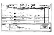
- FIG. 4 is an explanatory diagram of an example of a work schedule screen after work execution and reservation in the automatic analyzer according to the embodiment of the present invention.
- the user performed each operation prior to the morning inspection with respect to the reagent operation event 402, the calibration operation events 404 and 405, the quality control operation events 408 and 409, and the maintenance operation event 411.
- the reagent work event 401, the calibration work event 403, the quality control work event 407, the maintenance work event 411, and the work detail display area 413 are displayed as the work completed state.
- connections and broken lines are displayed so that the relationship with the work events 402, 404, 405, 408, and 409 displayed at the original occurrence time can be understood. That is, the work indicated by the broken circle (for example, the work event 402) is displayed as the black circle work that has been performed (for example, the work event 401), and both are connected by the broken arrow.
- the calibration work event, the quality control work event, and the maintenance work event can be performed prior to the afternoon inspection so that the occurrence of the work can be foreseen during the afternoon inspection.
- performing the work of the next person in charge time in advance reduces the work load of the next person in charge considering that the next person in charge is a person inexperienced in the apparatus. You can expect effects such as
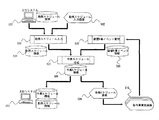
- FIG. 5 is an explanatory diagram of a data flow relating to a work schedule management function in the automatic analyzer according to one embodiment of the present invention.
- work schedule information 504 is created by receiving from the upper system USY connected via the network or by inputting from the work schedule input screen 502 of the operation unit PC 100.
- work event information 506 related to parameters registered in the device, reagent information and measurement, reagents predicted to be generated from the results of maintenance, calibration, accuracy management, and maintenance are created, to manage.
- work schedule information 508 for each person in charge is created based on the work schedule information 504 and the device work event information 506.
- the created work schedule information 508 is displayed on the work schedule screen 509. Also, the work schedule information 508 is transmitted to the upper system USY connected by the network.
- the user confirms the work on the work schedule screen, transitions to the work execution screen 510, and executes each work.
- the executed work event is fed back to the apparatus work event management process 505, and the work event information 506 is updated.
- the planning unit 112 in FIG. 2 plans in advance a work event required to use the apparatus, and performs the apparatus work event management process 505 in FIG. 5.
- the schedule creating unit 113 of FIG. 2 creates a time-series work schedule table as a list of tasks to be performed by the user within the assigned time, from the work schedule and the work events. It is something to do.
- the notification unit 114 in FIG. 2 urges the user to work when the reserved time is reached, and notifies the user on a work notification dialog screen 904 described later with reference to FIG.
- the reservation unit 116 in FIG. 2 is for the user to set an arbitrary scheduled operation time for the work event on the work schedule, and is inputted by the worker when the work reservation button 317 in FIG. 3 is depressed. Data is set.
- the determination unit 118 in FIG. 2 recognizes the work performed on the device, and automatically determines whether the work event displayed in the work schedule table has been performed or not, and the device work event management in FIG. 5 is performed. Process 505 is performed.
- the input unit 120 of FIG. 2 is for inputting the work schedule of the user using the apparatus, and as described above, constitutes a GUI together with the display unit 130 for displaying the presence or absence of work execution on the work schedule table.
- the work schedule information 504, the work event information 506, and the work schedule information 508 in FIG. 5 are stored in the storage unit 140 shown in FIG.
- the schedule table creation unit 113 creates a time-series work schedule table as a list of tasks that the user should perform within the assigned time from the work schedule and the work events.
- the created work schedule table is displayed on, for example, the work schedule screen 301 of FIG.
- the work implementation screen transition button 318 is pressed down. Thereby, the procedure for the reagent addition operation is displayed on the display screen of the display unit 130.
- the person in charge proceeds with the reagent addition operation, and when the reagent addition is completed, for example, when the button of “end of reagent addition” is displayed on the display unit 130, the schedule table creation unit 113 Recognize that the work has been completed.
- the schedule table creation unit 113 recognizes that the work has not been performed until the button of “end of reagent addition” is pressed.
- the determination as to whether the work has not been performed is performed by the determination unit 118 shown in FIG.
- the maintenance person to be performed represented by the maintenance operation display area 314 in FIG.
- the maintenance work that has not been performed is displayed on the work schedule screen 301 of FIG. 3 as the maintenance work event 315 of the person in charge.
- the work execution screen transition button 318 is depressed, and the reagent is displayed according to the procedure for the reagent addition work displayed on the display screen of the display unit 130
- the button of “end of reagent addition” displayed on the display unit 130 is pushed down.
- the work event information 506 is updated on the assumption that the reagent addition work is completed.
- the schedule table creation unit 113 can recognize that the work has been completed by referring to the work event information 506 by the work schedule creation processing 507, and is displayed on the work schedule screen 301 as the completed work event 401 in FIG. Ru.
- the calibration work event 406 is selected when the work is reserved before the inspection in the afternoon. Then, the details are displayed as shown in the work detail display area 316 of FIG. Then, the person in charge enters, for example, “8:30” in the “reservation time” column, and presses the reservation button 317 to change the reservation time after the change by the device work event management process 505 in FIG.
- the work event information 506 is updated to
- the schedule table creation unit 113 displays the work schedule after the change on the work schedule screen 301 as in the calibration work event 406 of FIG. 4 by referring to the work event information 506 by the work schedule creation processing 507. .
- FIG. 6 is an explanatory diagram of an example of a work schedule input screen in the automatic analysis device according to one embodiment of the present invention.
- the work schedule input screen 601 is a screen for a user at the manager level to register a daily inspection schedule and assignment of persons in charge. This screen is implemented on the operation unit PC of the automatic analyzer or on a host system connected via a network. In the case of a large hospital or laboratory, the number of apparatuses used is large and the number of persons in charge is also large, so it is efficient and preferable to implement and integrally manage in a higher system.
- the calendar 602 is used to select the inspection schedule and the date to which the assignee is assigned. A time is specified in the schedule input area 603 for the selected date, and a schedule is input. The input schedule is displayed in the schedule display area 605.
- a time is designated in the assigned input area 604, and a responsible person is input.
- the assignment of the input person in charge is displayed in the assignment assignment display area 606.
- the input schedule and assignment information of the person in charge are stored by pressing the registration button 607.
- this screen is implemented in the upper system, a plurality of devices are to be managed, and therefore, the information for identifying the devices is added, and the screen layout is such that the schedule input for each device is performed.
- FIG. 7 is an explanatory diagram of an example of a work schedule management setting screen in the automatic analyzer according to one embodiment of the present invention.
- the work schedule management setting screen 701 is a screen for performing settings such as screen display in the work schedule management function, work notification, and communication with the upper system.
- the log-in work schedule display setting column 702 is used to set whether or not to automatically display a work schedule screen of the logged-in user when the user logs in to the system on the operation unit PC.
- the work schedule display setting column 703 is used to set whether or not to automatically display the work schedule screen of the login user when the user logs out of the system.
- the user can confirm the work schedule that he / she must perform within the assigned time when logging in to the system, and can make an efficient work plan. it can. Also, when logging out of the system, it can be confirmed that there is no work omission.
- the work notification setting field 704 is used to set whether or not to display a notification for prompting the user to work when the time of occurrence of each work event or when the user has made a reservation is reached.
- Be The work notification time setting field 705 is a setting of a time for performing work notification in advance.
- the combined work notification setting column 706 and the combined work notification time setting column 707 recommend that when a certain work event reaches the work time, the work time to arrive within the specified time starting from that time be collectively implemented It is used to set whether or not to display a notification.
- the work notification before completion of work time setting column 708 and the work notification time before completion of work time setting column 709 are used for setting to notify the remaining work before the specified time of completion of the work time.
- the notified time is managed by the notification unit 114 shown in FIG.
- the notification unit 114 notifies the user on the work notification dialog screen 904 described later with reference to FIG.
- the work schedule upper system reception setting column 710 sets whether or not work schedule information necessary for creating work schedule information is received from a higher system connected via a network.
- the work schedule upper system transmission setting field 711 sets whether to transmit the created work schedule information to the upper system.
- the information input on this screen is saved by pressing the setting button 712.
- FIG. 8 is a flowchart showing the contents of work schedule creation and management processing in the automatic analyzer according to one embodiment of the present invention.
- step 801 it is determined whether there is a work schedule reception setting from the host system. If there is a setting, work schedule information is received from a host system connected via a network at step 802.
- step 803 work schedule information is read. If the setting is not made at step 801, the work schedule information registered on the work schedule input screen on the operation unit PC is read.
- step 804 the apparatus operation event information on parameters registered in the apparatus, information and measurement of the reagent, reagents predicted to be generated from the results of maintenance, maintenance, calibration, quality control, and maintenance is read.
- step 805 based on the work schedule information read at step 803, the apparatus work event information read at step 804 is incorporated to create a work schedule for each person in charge. This is the process of creating a work schedule.
- step 806 it is determined whether there is a work event that has reached the notification time. If there is a work event, it is determined in step 807 whether there is a work event that reaches the notification time within the specified time. If there is, the user is notified in step 808 to perform the corresponding work collectively. If not, the user is notified in step 809 to carry out the work individually.
- the time of addition of the reagent is determined by the remaining amount of each reagent, and therefore, is different from each other.
- a second reagent addition work event is scheduled to occur 10 minutes after the first reagent addition work event, secondly following the first reagent addition.
- the addition of reagents saves the trouble of adding reagents. In such a case, it is considered appropriate to carry out the work collectively.
- calibration is generally performed at regular intervals in consideration of deterioration of the reagent.
- quality control is generally performed each time measurement of a predetermined number of samples is performed. If calibration and accuracy control for a given reagent are scheduled at a slightly separated timing, it is more efficient to perform this sequentially. In such cases, it is considered appropriate to carry out the work collectively.
- step 810 it is determined whether or not the set time for termination of the assigned time is over. If it does, the user is notified in step 811 to carry out the work with the unexecuted work event within the assigned time as the remaining work.
- step 812 it is determined whether there is an operation that could not be performed within the assigned time. In some cases, the remaining work is carried over to the work schedule of the next person in charge in step 813.
- step 814 it is determined whether there is a work schedule transmission setting to the upper system, and if there is, work schedule information is transmitted to the upper system in step 815.
- FIG. 9 is an explanatory diagram of an example of a work notification dialog screen in the automatic analyzer according to one embodiment of the present invention.
- FIG. 8 shows the case where the task notification dialog screen 904 is displayed while the user is using the patient sample measurement result screen 901.
- the task notification dialog screen 901 displays the content of the task for prompting execution in the task detail display area 905. If there are multiple tasks, they will be displayed in a list format. By pressing the work execution screen transition button 906 displayed for each work, the screen can be directly transitioned to each work execution screen for performing the corresponding work, and the work can be performed promptly.
- the work schedule screen transition button 903 is a button for displaying a work schedule screen. It is preferable that this button is arranged in the global non-screen dependent display area 902 which does not depend on the display of each screen so that the work schedule screen can be displayed from any screen.
- a list of tasks to be performed within the assigned time may be displayed.
- the user can confirm the work at the start of the work, and can make an efficient work plan according to the work schedule.
- the work schedule to be performed by the user within the assigned time can be integrated and managed across multiple devices, and the burden on the user can be alleviated and the work schedule can be efficiently managed in a large-scale inspection facility.
- reagent work display area 309 ... reagent work event 310 ... calibration work display area 311 . calibration work event 312 ... quality control work display area 13 ... Accuracy management work event 314 ... Maintenance work display area 315 ... Maintenance work event 316 ... Work detail display area 317 ... Work reservation button 318 ... Work execution screen transition button 401, 402 ... Reagent work event 403 to 406 ... Calibration work event 407-410 ... Quality control work event 411, 412 ... Maintenance work event 413 ... Work detail display area 502 ... Work schedule input screen 503 ... Work schedule input processing 504 ... Work schedule information 505 ... Equipment work event management processing 506 ... Equipment work event Information 507 ... Work schedule creation process 508 ...
- Flow chart step 901 ... Patient sample measurement result screen 902 ... Non-screen dependent display area 903 ... Work schedule screen transition button 904 ... Work notification Dialog screen 905 ... Work details display area 906 . Work implementation screen transition button 907 ... Work schedule screen transition button 908 ... Close button
Landscapes
- Business, Economics & Management (AREA)
- Human Resources & Organizations (AREA)
- Engineering & Computer Science (AREA)
- General Business, Economics & Management (AREA)
- Health & Medical Sciences (AREA)
- Economics (AREA)
- Entrepreneurship & Innovation (AREA)
- Strategic Management (AREA)
- Physics & Mathematics (AREA)
- General Physics & Mathematics (AREA)
- Biomedical Technology (AREA)
- General Health & Medical Sciences (AREA)
- Theoretical Computer Science (AREA)
- Development Economics (AREA)
- Quality & Reliability (AREA)
- Operations Research (AREA)
- Marketing (AREA)
- Game Theory and Decision Science (AREA)
- Tourism & Hospitality (AREA)
- Educational Administration (AREA)
- Epidemiology (AREA)
- Medical Informatics (AREA)
- Primary Health Care (AREA)
- Public Health (AREA)
- Analytical Chemistry (AREA)
- Biochemistry (AREA)
- Chemical & Material Sciences (AREA)
- Immunology (AREA)
- Pathology (AREA)
- Life Sciences & Earth Sciences (AREA)
- Automatic Analysis And Handling Materials Therefor (AREA)
- Management, Administration, Business Operations System, And Electronic Commerce (AREA)
Abstract
入力部120から、装置を使用するユーザの勤務スケジュールが入力される。計画部112は、装置を使用する上で必要となる作業イベントを予め計画する。スケジュール作成部113は、入力部から入力された勤務スケジュールと計画部で計画された作業イベントから、ユーザが担当時間内に行うべき作業の一覧として時系列な作業スケジュールを作成する。表示部130には、スケジュール作成部により作成された作業スケジュールが表示される。これにより、ユーザが担当時間内に行うべき作業を事前に予見し、自身の勤務スケジュールに合わせて効率的に作業を計画し、漏れなく実施することができる。
Description
本発明は、血液,尿等の生体試料の測定を行う自動分析装置に係り、特に、自動分析装置におけるユーザの作業スケジュールを効率的に計画、管理するためのユーザインタフェースを有する自動分析装置に関する。
血液や尿等の生体試料と試薬を用いて分析する自動分析装置においては、分析開始時、もしくは分析処理中に各試薬に応じて定まる所定時間毎に、あるいは分析処理中の必要に応じて、検量線校正操作であるキャリブレーションや自動分析装置が良好な状態を保つための精度管理を行う必要がある。
キャリブレーションや精度管理を実施すべき要因としては、キャリブレーションや精度管理を一定の周期で実行させるための所定時間が経過した場合や、試薬のボトルを切り替えた後や、測定失敗時の再測定などがある。
キャリブレーションは、各項目に応じて定められた濃度の標準液を用いて行なわれる。キャリブレーションや精度管理には各分析項目に応じた有効期限がある。このため有効期限を過ぎると再キャリブレーションや再精度管理を行わなければならない。また各分析項目において、一つの試薬ボトルの試薬を使いきり、新しい試薬ボトルの試薬を使う場合にも再キャリブレーションや再精度管理を行わなければならない。
従来の自動分析装置では、前述の各試薬に応じて定まる所定時間や、有効期限、新しい試薬ボトルへの切り替え等を装置が自動的に検知し、ユーザにキャリブレーションや精度管理の実施が必要なことを通知するものが知られている(例えば、特許文献1参照)。
特許文献1記載の機能は、ある時点で即時にキャリブレーションや精度管理検体分析が必要かどうかを分析項目毎に示す有効な技術であるが、いずれの要因に対してもユーザが実施要否を知ることができるのはそれが間近に迫った時である。従来は、将来の一定期間に対し、キャリブレーションや精度管理の必要性を予測し、分析予定を立てる手段はなかった。このためユーザにとっては、キャリブレーション用の標準試料や、精度管理用のコントロール検体、及びこれらを分析するための試薬等の準備および分析を計画的に行うことが困難であった。
また、近年では装置の性能向上のため機器の高精密化、高感度化が進み、それに伴い装置を維持管理するためのメンテナンス機能が増加している。メンテナンス機能としては、例えば、自動分析装置に組み込まれた光度計の光源を所定時間毎に交換する必要があるというものである。このようなメンテナンス機能に関しても定期的な実行が必要であり、従来の自動分析装置も期限を管理する機能を有していた。しかし、前述のキャリブレーションや精度管理と同様にユーザが実施要否を知ることができるのはそれが間近に迫った時であり、メンテナンスを計画的に行うことが難しかった。
更に、自動分析装置を使用する検査室の多くは24時間運用などで複数のユーザが勤務時間をシフトし交代して運用に当たっている。このため、各ユーザが担当時間内で発生する前述の作業イベントを漏れなく実施し次の担当ユーザに引き継ぐことが重要である。
しかし、従来の自動分析装置ではユーザの勤務スケジュールを入力する術は無く、装置はユーザの勤務スケジュールと連動せず五月雨的に通知するだけであり、効率的に作業を計画、実施できず作業漏れの原因となり、性能を保証する上で重大な問題となる可能性があった。
大規模な検査施設ではユーザが扱う装置が多いことや、同時に複数のユーザが作業することから、作業漏れが発生するなど、非効率な作業となるポテンシャルが更に高まる。
そこで、本発明の目的は、ユーザが担当時間内に行うべき作業を事前に予見し、自身の勤務スケジュールに合わせて効率的に作業を計画し、漏れなく実施することができる自動分析装置を提供することにある。
上記目的を達成するために、本発明は、装置を使用するユーザの勤務スケジュールを入力する入力部と、前記装置を使用する上で必要となる作業イベントを予め計画する計画部と、前記入力部から入力された前記勤務スケジュールと前記計画部で計画された前記作業イベントから、ユーザが担当時間内に行うべき作業の一覧として時系列な作業スケジュールを作成するスケジュール作成部と、該スケジュール作成部により作成された前記作業スケジュールを表示する表示部とを備えるようにしたものである。
かかる構成により、ユーザが担当時間内に行うべき作業を事前に予見し、自身の勤務スケジュールに合わせて効率的に作業を計画し、漏れなく実施することができるものとなる。
かかる構成により、ユーザが担当時間内に行うべき作業を事前に予見し、自身の勤務スケジュールに合わせて効率的に作業を計画し、漏れなく実施することができるものとなる。
本発明によれば、ユーザが担当時間内に行うべき作業を事前に予見し、自身の勤務スケジュールに合わせて効率的に作業を計画し、漏れなく実施することができるものとなる。
以下、図1~図9を用いて、本発明の一実施形態による自動分析装置の構成及び動作について説明する。
最初に、図1を用いて、本実施形態による自動分析装置の全体構成について説明する。
図1は、本発明の一実施形態による自動分析装置の全体構成を示すシステム構成図である。
最初に、図1を用いて、本実施形態による自動分析装置の全体構成について説明する。
図1は、本発明の一実施形態による自動分析装置の全体構成を示すシステム構成図である。
本実施形態の自動分析装置は、例えば、直列配置された3台の分析部AA1,AA2,AA3を備えている。なお、分析部の数は3個に限らず、複数若しくは単数でも良いものである。各分析部AA1,AA2,AA3に隣接して、試料ラックを搬送する搬送ラインTRLが設けられている。また、直列配置された各分析部AA1,AA2,AA3の一方の端部側に、試料投入部SAIが設けられ、他方の端部に試料収納部SAOが設けられている。
ユーザUSRは、キャリブレーション測定、精度管理試料測定、患者試料測定で対象となる試料SMPは試料ラックSMLに搭載する。試料ラックSMLには、複数個の試料が搭載可能である。試料を搭載した試料ラックSMLは試料投入部SAIに設置される。設置された試料ラックSMLは順に搬送ライン305に搬入され、試料に対する分析を行う分析部AA1,AA2,AA3に搬送される。分析部AA1,AA2,AA3は、それぞれ、試料ラックSMLおよび試料SMPを認識し、試料SMPに必要な分析を行う。各分析部AA1,AA2,AA3は、分析を行うために使用する複数の試薬REGを収納する試薬ディスクREDを備える。分析に必要な試薬REGはユーザによって分析に先立ち前もって試薬ディスクREDに設置される。必要な分析が行われた試料ラックSMLは試料収納部SAOに搬送される。
試料投入部SAI,分析部AA1,AA2,AA3,試料収納部SAOは、それぞれネットワークケーブルでハブHBを介して自動分析装置の操作部PC100に接続される。操作部PC100は、ネットワークにて上位ホストシステムUSYに接続される。
ユーザは、上位ホストシステムUSYまたは操作部PC100から各試料に対する分析依頼(測定依頼)を行い、分析する試料を試料ラックSMLに搭載し、試料投入部SAIへ設置する。分析依頼された情報はネットワークを介して分析部AA1,AA2,AA3に送信され、分析部AA1,AA2,AA3にて分析した結果は操作部PC100および上位ホストシステムUSYへ送信される。
また、操作部PC100は公衆回線を介してリモートシステムRSYに接続される。リモートシステムRSYには自動分析装置で使用する試薬を使用した分析条件情報である分析パラメータ等の情報を蓄積しており、操作部PC100からの要求により分析パラメータの配信を行う。配信された分析パラメータは操作部PC100に記憶され、試料の分析時に分析部AA1,AA2,AA3へ送信される。
本実施形態による作業スケジュール管理機能は、操作部PC100に画面インタフェースを備えることが、システム構成および操作性の観点から最良な形態である。操作部PC100または自動分析装置の上位システムである上位ホストシステムUSYまたはリモートシステムRSYにて入力された勤務スケジュール情報および操作部PC100で管理している装置の作業イベント情報から、操作部PC100は、担当者毎の作業スケジュール情報を作成する。
ユーザは、操作部PC100に表示された作業スケジュール画面にて自身が行わなければならない作業を確認し、勤務スケジュール合わせて効率的な作業の計画を立てることができる。
また、ユーザの利用形態にあわせて上位システムである上位ホストシステムまたはリモートシステム上に作業スケジュール管理部を備え、ネットワークを経由して操作部PCおよび分析部と情報を送受信し機能を実現しても良い。
次に、図2を用いて、本実施形態による自動分析装置に用いる操作部PC100の構成について説明する。
図2は、本発明の一実施形態による自動分析装置に用いる操作部PCの構成を示すブロック図である。
図2は、本発明の一実施形態による自動分析装置に用いる操作部PCの構成を示すブロック図である。
操作部PC100は、主として、制御部110と、入力部120と、表示部130と、記憶部140とから構成される。入力部120は、キーボードやマウスからなる。表示部130に表示されたボタンの表示を押し下げ(マウスでクリック)したり、表示部130に表示された入力枠にキーボードから数字や文字を入力したりすることができる。入力部120と表示部130とによって、GUI(グラフィックユーザインターフェース)を構成している。
制御部110は、計画部112と、スケジュール作成部113と、通知部114と、予約部116と、判別部118とを備えているが、これらの機能や動作については、後述する。
記憶部140には、前述した勤務スケジュール情報や作業イベント情報が記憶される。計画部112は、これらの情報を用いて、作業スケジュールを計画する。
次に、図3を用いて、本実施形態による自動分析装置における作業スケジュール画面の一例について説明する。
図3は、本発明の一実施形態による自動分析装置における作業スケジュール画面の一例の説明図である。
図3は、本発明の一実施形態による自動分析装置における作業スケジュール画面の一例の説明図である。
作業スケジュール画面301は、図2の表示部130に表示される。作業スケジュール画面301には、操作部PC100にログインしたユーザが担当時間内に行わなければならない作業の一覧をタイムスケジュールとして表示する。
ログインユーザ302の欄には、現在ログインしているユーザの氏名が表示される。作業スケジュール画面301の初期表示はログインユーザの当該時間帯の作業スケジュールが中央に表示されるようにすることで、作業ユーザに最適な表示となる。
担当前後移動ボタン303は、ログインユーザより前の担当者、後の担当者の作業スケジュールを表示するためのボタンである。時間前後移動ボタン304は1時間単位で作業スケジュールの表示をスクロールするためのボタンである。担当前後移動ボタン303や時間前後移動ボタン304を使用することで、自身の作業スケジュールを確認できるだけでなく、前の担当者の作業状況や後の担当者の作業予定を確認することができる。
スケジュール表示エリア305は、病院や検査室のスケジュールを表示する。試薬作業表示エリア308は、試薬不足に伴う試薬追加などの試薬作業イベント309を表示する。キャリブレーション作業表示エリア310は、試薬追加やタイムアウトに伴うキャリブレーション測定などのキャリブレーション作業イベント311を表示する。精度管理作業表示エリア312は、試薬追加やタイムアウトに伴う精度管理測定などの精度管理作業イベント313を表示する。メンテナンス作業表示エリア314は、タイムアウトや部品交換に伴うメンテナンス実施などのメンテナンス作業イベント315を表示する。各作業イベントは作業の実施状況によりマークを変えることで視認性を良くすることが好ましい。
また、作業スケジュール画面301には、ログインユーザの担当時間枠306、および現在時刻線307を表示する。
以上の表示により、担当者が担当時間内で行うべき作業を容易に確認することができ、病院や検査室のスケジュールに対して、どのようなタイミングで作業が発生するか確認でき、効率的に作業できるか否か判断することができる。
なお、本画面に表示する作業イベントの種類としては画面例の通り、自動分析装置として性能保証上で最も重要な試薬、キャリブレーション、精度管理、メンテナンスに関わる作業とすることが最適であるが、使用するユーザの目的によってカスタマイズ可能であることが望ましい。図3の表示例では午後の検査中に試薬作業イベント309、キャリブレーション作業イベント311、精度管理作業イベント313等が発生することが予見でき、午前の検査が中断される恐れがあることを知ることができる。尚、メンテナンス作業イベント315は、破線の丸と実線の丸とを矢印で結んで表示することで、前担当者が作業を実施しなかったため、ログインユーザに繰り越しされた作業を表している。
作業詳細表示エリア316は、本画面上で選択された作業イベントの詳細内容を表示する。図3の例では試薬作業イベント309が選択されている状態である。図3では、試薬作業表示エリア308の試薬作業イベント309を太い輪で囲んでいるが、これが例えば選択された状態を示している。なお、実際の画面では、選択されたイベント等の○のマークの色を変えたりして、選択されていることを表示している。
作業詳細エリア316は、作業の実施ステータス、発生時刻、予約時刻、実施時刻、実施者および作業内容を表示する。また、上記のように発生時刻がスケジュール上、都合が悪い場合に予め都合がよい時刻に作業を予約する作業予約ボタン317を備える。また、作業実施画面遷移ボタン318を備えることで、作業を実施するための各作業実施画面へダイレクトに画面遷移し迅速に作業を行うことができる。このような作業スケジュール画面301をユーザが操作部PC100にログインした際に自動的に表示することで、ユーザは担当時間内に行うべき作業を確認し、効率的な作業の計画を立てることができる。また、ユーザが操作部PC100からログアウトする際に、作業スケジュール画面301を自動的に表示することで、ユーザは担当時間内に行うべき作業で忘れている物がないかどうかを確認することができる。
次に、図4を用いて、本実施形態による自動分析装置における作業実施および予約後の作業スケジュール画面の一例について説明する。
図4は、本発明の一実施形態による自動分析装置における作業実施および予約後の作業スケジュール画面の一例の説明図である。
図4は、本発明の一実施形態による自動分析装置における作業実施および予約後の作業スケジュール画面の一例の説明図である。
図3に示した表示例では、午後の検査中に試薬作業イベント、キャリブレーション作業イベント、精度管理作業イベント等が発生することが予見でき、午前の検査が中断される恐れがあることを知ることができた。
これに対してユーザは、試薬作業イベント402、キャリブレーション作業イベント404および405、精度管理作業イベント408および409、メンテナンス作業イベント411に関して午前の検査に先立ち各作業を実施した。その結果、試薬作業イベント401、キャリブレーション作業イベント403、精度管理作業イベント407、メンテナンス作業イベント411および作業詳細表示エリア413のように作業済の状態として表示する。また、もともとの発生時刻に表示された作業イベント402、404,405,408,409との関連が分かるよう結線や破線用い表示している。すなわち、破線の丸で示した作業(例えば、作業イベント402)が、黒丸の実施済みの作業(例えば、作業イベント401)として表示され、両者が破線矢印で結ばれる。
更に、午後の検査中に作業の発生が予見できるキャリブレーション作業イベント、精度管理作業イベント、メンテナンス作業イベントを午後の検査に先立って行えるよう、作業イベント406、410、412のように午後の検査前に作業の予約を行った。すなわち、破線の丸で示した作業が、ハッチングの丸(例えば、作業イベント406)として表示され、両者が破線矢印で結ばれる。特に作業イベント412のケースのように次担当者の担当時間の作業を前もって実施することは、次担当者が装置に不慣れな担当者である場合などを考慮して次担当者の作業負担を軽減するなどの効果も期待できる。
また、図3のスケジュール表示エリア305にユーザが任意のスケジュールを登録できるような機能を設けることで、装置上の作業イベントのみならず勤務における総合的なスケジュール管理が可能になる。以上のような表示および作業予約の機能により、作業の実施状況を容易に確認することができ、更には勤務スケジュールに合わせて効率的な作業の計画を立てることができる。
次に、図5を用いて、本実施形態による自動分析装置における作業スケジュール管理機能に関するデータの流れについて説明する。
図5は、本発明の一実施形態による自動分析装置における作業スケジュール管理機能に関するデータの流れの説明図である。
図5は、本発明の一実施形態による自動分析装置における作業スケジュール管理機能に関するデータの流れの説明図である。
勤務スケジュール入力処理503では、ネットワークで接続された上位システムUSYから受信したり、または操作部PC100の勤務スケジュール入力画面502から入力により勤務スケジュール情報504を作成する。
また、装置作業イベント管理処理505では、装置に登録されたパラメータ、試薬の情報および測定、メンテナンスの実績から発生が予測される試薬、キャリブレーション、精度管理、メンテナンスに関する作業イベント情報506を作成し、管理する。
作業スケジュール作成処理507では、勤務スケジュール情報504および装置作業イベント情報506を元に担当者毎の作業スケジュール情報508を作成する。作成された作業スケジュール情報508は、作業スケジュール画面509に表示される。また、作業スケジュール情報508は、ネットワークで接続された上位システムUSYに送信される。
ユーザは作業スケジュール画面で作業を確認し、各作業実施画面510に画面遷移して各作業を実行する。実行した作業イベントは装置作業イベント管理処理505にフィードバックされ、作業イベント情報506が更新される。
ここで、図2に示した各部と、図5との対応関係について説明する。
図2の計画部112は、装置を使用する上で必要となる作業イベントを予め計画するものであり、図5の装置作業イベント管理処理505を行うものである。
図2のスケジュール作成部113は、勤務スケジュールと作業イベントから、ユーザが担当時間内に行うべき作業の一覧として時系列な作業スケジュール表を作成するものであり、図5の作業スケジュール作成処理507を行うものである。
図2の通知部114は、予約した時刻に到達するとユーザに作業を促すものであり、図9で後述する作業通知ダイアログ画面904にて通知する。
図2の予約部116は、作業スケジュール上の作業イベントに対してユーザが任意の実施予定時刻を設定するものであり、図3の作業予約ボタン317が押し下げされることで、作業者によって入力されたデータが設定される。
図2の判別部118は、装置上で行った作業を認識し、作業スケジュール表に表示された作業イベントが実施済か否かを自動的に判別するものであり、図5の装置作業イベント管理処理505を行うものである。
図2の入力部120は、装置を使用するユーザの勤務スケジュールを入力するものであり、前述したように、作業スケジュール表上に作業実施の有無を表示する表示部130とともに、GUIを構成する。
図2に示した記憶部140には、図5における勤務スケジュール情報504、作業イベント情報506、作業スケジュール情報508が記憶される。
次に、具体的な例を用いて、各部の動作について説明する。
スケジュール表作成部113は、勤務スケジュールと作業イベントから、ユーザが担当時間内に行うべき作業の一覧として時系列な作業スケジュール表を作成する。作成された作業スケジュール表は、例えば、図3の作業スケジュール画面301に表示される。例えば、ログインした担当者が、作業スケジュール画面301を見て、試薬作業イベント309を実行しようとすると、作業実施画面遷移ボタン318を押し下げる。それにより、表示部130の表示画面には、試薬追加作業のための手順が表示される。担当者は、この手順に従って、試薬追加の作業を進め、試薬追加が終了すると、表示部130に表示されている,例えば、「試薬追加終了」のボタンを押し下げると、スケジュール表作成部113は、当該作業が終了したと認識する。
一方、「試薬追加終了」のボタンの押下げが行われるまでは、スケジュール表作成部113は、当該作業が未実施であると認識する。作業の実施未実施等の判別は、図2の判別部118により行われる。
例えば、図3のメンテナンス作業表示エリア314に表されている前担当者が実施すべきメンテナンス作業が未実施のまま前担当者から現在の担当者の時間帯に移行するとき、スケジュール表作成部113は、未実施のメンテナンス作業を、当該担当者のメンテナンス作業イベント315として、図3の作業スケジュール画面301に表示する。
また、例えば、図4の試薬追加に関する作業イベント402を前倒しで行った場合、作業実施画面遷移ボタン318を押し下げて、表示部130の表示画面に表示された試薬追加作業のための手順に従って、試薬追加の作業を進め、試薬追加が終了すると、表示部130に表示されている「試薬追加終了」のボタンを押し下げる。これにより、図5の装置作業イベント管理処理505で、当該試薬追加作業が終了したとして、作業イベント情報506が更新される。スケジュール表作成部113は、作業スケジュール作成処理507により、作業イベント情報506を参照することで、当該作業が終了したと認識でき、図4の実施済みの作業イベント401として作業スケジュール画面301に表示される。
また、図4に示したキャリブレーション作業イベント406を、午後の検査に先立って行えるよう、午後の検査前に作業の予約を行う場合には、キャリブレーション作業イベント406を選択する。すると、その詳細は、図3の作業詳細表示エリア316のように表示される。その上で、担当者は、「予約時刻」の欄に例えば、「8:30」と入力し、予約ボタン317を押し下げことで、図5の装置作業イベント管理処理505により、変更後の予約時間に作業イベント情報506が更新される。スケジュール表作成部113は、作業スケジュール作成処理507により、作業イベント情報506を参照することで、変更後の作業予定を、図4のキャリブレーション作業イベント406のように、作業スケジュール画面301に表示する。
次に、図6を用いて、本実施形態による自動分析装置における勤務スケジュール入力画面の一例について説明する。
図6は、本発明の一実施形態による自動分析装置における勤務スケジュール入力画面の一例の説明図である。
図6は、本発明の一実施形態による自動分析装置における勤務スケジュール入力画面の一例の説明図である。
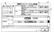
勤務スケジュール入力画面601は、管理者レベルのユーザが日々の検査スケジュールおよび担当者の割り当てを登録する画面である。本画面は自動分析装置の操作部PC上またはネットワークで接続された上位システム上に実装される。大規模な病院や検査室の場合は使用する装置の数も多く、また担当者の数も多くなるため、上位システムに実装し統合管理することが効率的であり好ましい。
カレンダー602は、検査スケジュールおよび担当者を割り当てる日付を選択するために用いられる。選択した日付に対してスケジュール入力エリア603にて時刻を指定し予定を入力する。入力したスケジュールはスケジュール表示エリア605に表示される。
また、担当入力エリア604にて時刻を指定し、担当者を入力する。入力された担当者の割り当ては、担当割当て表示エリア606に表示される。
入力したスケジュールおよび担当者の割り当て情報は登録ボタン607を押下することによって保存される。尚、本画面が上位システムに実装される場合は、複数の装置が管理の対象となるため、装置を識別する情報を追加し、装置毎のスケジュール入力を行うような画面レイアウトとなる。
次に、図7を用いて、本実施形態による自動分析装置における作業スケジュール管理設定画面の一例について説明する。
図7は、本発明の一実施形態による自動分析装置における作業スケジュール管理設定画面の一例の説明図である。
図7は、本発明の一実施形態による自動分析装置における作業スケジュール管理設定画面の一例の説明図である。
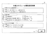
作業スケジュール管理設定画面701は、作業スケジュール管理機能における画面表示、作業通知、上位システムとの通信などの設定を行う画面である。
ログイン時作業スケジュール表示設定欄702は、ユーザが操作部PC上でシステムにログインした際にログインユーザの作業スケジュール画面を自動的に表示するか否かの設定を行うために用いられる。
同様に、ログアウト時作業スケジュール表示設定欄703は、ユーザがシステムからログアウトする際にログインユーザの作業スケジュール画面を自動的に表示するか否かの設定を行うために用いられる。
このような作業スケジュール画面の表示機能を設けることによりユーザはシステムにログインする際に自身が担当時間内に行わなければならない作業のスケジュールを確認することができ、効率的な作業計画を立てることができる。また、システムからログアウトする際に作業漏れが無いことを確認することができる。
作業通知設定欄704は、各作業イベントの発生時刻またはユーザが予約している場合は予約時刻に到達した時点でユーザに作業を促すための通知表示を行うか否かの設定を行うために用いられる。作業通知時間設定欄705は、作業通知を前もって行う時間の設定である。
集約作業通知設定欄706および集約作業通知時間設定欄707はある作業イベントが作業時刻に到達した際に、その時刻を起点にした規定時間内に作業時刻に到達する作業を纏めて実施するよう推奨するための通知表示を行うか否かの設定を行うために用いられる。
担当時間終了前作業通知設定欄708および担当時間終了前作業通知時間設定欄709は、担当時間終了の規定時間前に残作業を通知する設定のために用いられる。このような作業の通知機能を設けることによりユーザに作業を促すことで作業漏れを防止することができる。
作業通知設定欄704、作業通知時間設定欄705、集約作業通知設定欄706、集約作業通知時間設定欄707、担当時間終了前作業通知設定欄、担当時間終了前作業通知時間設定欄709にて設定された時間は、図2に示した通知部114によって管理される。通知部114は、予約した時刻に到達すると、図9で後述する作業通知ダイアログ画面904にてユーザに作業を促すために、通知する。
勤務スケジュール上位システム受信設定欄710は、作業スケジュール情報を作成するために必要となる勤務スケジュール情報をネットワークで接続された上位システムから受信するか否かを設定する。また、作業スケジュール上位システム送信設定欄711は作成した作業スケジュール情報を上位システムに送信するか否かを設定する。
このような上位システムとの通信機能を設けることにより、上位システムと自動分析装置間の情報共有を行うことを可能とし、大規模な病院や検査施設の複数の装置や複数のユーザを上位システムにて効率的に統合管理することができる。
本画面で入力された情報は設定ボタン712を押下することによって保存される。
次に、図8を用いて、本実施形態による自動分析装置における作業スケジュール作成および管理処理の内容について説明する。
図8は、本発明の一実施形態による自動分析装置における作業スケジュール作成および管理処理の内容を示すフローチャートである。
図8は、本発明の一実施形態による自動分析装置における作業スケジュール作成および管理処理の内容を示すフローチャートである。
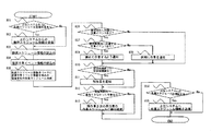
ステップ801にて、上位システムからの勤務スケジュール受信設定があるか判定する。設定ありの場合はステップ802にてネットワークで接続された上位システムから勤務スケジュール情報を受信する。
ステップ803にて、勤務スケジュール情報を読込む。尚、ステップ801にて設定なしの場合は操作部PC上の勤務スケジュール入力画面で登録された勤務スケジュール情報を読込むこととなる。
次に、ステップ804にて、装置に登録されたパラメータ、試薬の情報および測定、メンテナンスの実績から発生が予測される試薬、キャリブレーション、精度管理、メンテナンスに関する装置作業イベント情報を読込む。
ステップ805では、ステップ803で読込んだ勤務スケジュール情報をベースにステップ804で読込んだ装置作業イベント情報を組込み、担当者毎の作業スケジュールを作成する。ここまでが作業スケジュールを作成する処理となる。
これ以降は作業スケジュールを管理する処理となる。まず、ステップ806にて、通知時刻に到達した作業イベントがあるか判定する。ある場合はステップ807にて、規定時間内に通知時刻に到達する作業イベントがあるか判定する。ある場合はステップ808にて該当する作業を纏めて実施するようユーザに通知する。ない場合はステップ809にて個別に作業を実施するようユーザに通知する。
作業を纏めて実施する方が適当な場合とは次のような場合である。例えば、試薬追加作業についてみると、試薬追加の時期は、それぞれの試薬の残量で決まるため、それぞれ異なる時期となる。但し、例えば、第1の試薬追加の作業イベントの10分後に、第2の試薬追加の作業イベントが発生するようにスケジュールされている場合には、第1の試薬追加に続いて、第2に試薬追加を行う方が、試薬追加の手間が省ける。このような場合に、作業をまとめて実施するのが適当と判断される。
また、キャリブレーションは、試薬の劣化を考えて、一定時間毎に行われるのが一般的である。一方、精度管理は所定の検体数の測定が行われるたびに行われるのが一般的である。仮に、所定の試薬に対するキャリブレーションと精度管理が少し離れたタイミングでスケジュールされている場合は、これは、順次行った方が効率的である。のような場合に、作業をまとめて実施するのが適当と判断される。
次に、ステップ810にて担当時間終了の設定時間前か判定する。該当する場合はステップ811にて担当時間内の未実施の作業イベントを残作業として作業を実施するようユーザに通知する。
次に、ステップ812にて担当時間内に実施できなかった作業があるか判定する。ある場合にはステップ813にて残作業を次の担当者の作業スケジュールに繰り越す。
最後にステップ814にて上位システムへの作業スケジュール送信設定があるか判定し、ある場合にはステップ815にて上位システムへ作業スケジュール情報を送信する。
次に、図9を用いて、本実施形態による自動分析装置における作業通知ダイアログ画面の一例について説明する。
図9は、本発明の一実施形態による自動分析装置における作業通知ダイアログ画面の一例の説明図である。
図9は、本発明の一実施形態による自動分析装置における作業通知ダイアログ画面の一例の説明図である。
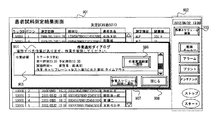
作業の実施時刻に到達するとユーザに作業の実施を促すため、本ダイアログ画面901を表示する。図8はユーザが患者試料測定結果画面901を使用している最中に作業通知ダイアログ画面904が表示されたケースである。
作業通知ダイアログ画面901は、作業詳細表示エリア905に実施を促す作業の内容を表示する。尚、複数の作業がある場合はリスト形式で表示される。各作業毎に表示された作業実施画面遷移ボタン906は押下することで該当の作業を実施するための各作業実施画面へダイレクトに画面遷移し、迅速に作業を行うことができる。
作業スケジュール画面遷移ボタン907は押下することで作業スケジュール画面に遷移し、作業スケジュールを確認することができる。
閉じるボタン908を押下することで本作業通知ダイアログ画面を閉じる。
このような作業通知機能を設けることによって、ユーザは別な作業をしていても予定の時刻に作業が通知され作業漏れを防止することができる。
作業スケジュール画面遷移ボタン903は、作業スケジュール画面を表示するためのボタンである。本ボタンはどの画面からでも作業スケジュール画面が表示できるよう各画面の表示に依存しないグローバルな非画面依存表示領域902に配置されることが好ましい。
以上説明したように、本実施形態によれば、事前にユーザの勤務スケジュールを入力しておくことによって、ユーザが装置の操作部にログインした際に、担当時間内に行うべき作業の一覧を時系列な作業スケジュール表として表示することで、ユーザは業務開始時に作業を確認することができ、勤務スケジュール合わせて効率的な作業の計画を立てることができる。
また、作業の予定時刻や未実施の作業を自動的にユーザに通知し、作業を促す機能や、未実施の作業を次の担当者の作業スケジュールに繰り越す機能によって、作業漏れを防止することができる。また、前後の担当者の作業スケジュールを照会することによって、作業の実施状況の確認や、不慣れな担当者の作業を前もって実施することも可能となる。
更に、ネットワークで接続された複数の装置を統合管理する上位システムからユーザの勤務スケジュールに関する情報を受信し、作成した作業スケジュールに関する情報を上位システムに送信する通信機能を備えることによって、上位システム上で複数の装置に跨ってユーザが担当時間内に行うべき作業スケジュールを統合管理することができ、ユーザの負担を軽減するとともに大規模な検査施設での作業スケジュールの管理を効率的に行うことができる。
100…操作部PC
110…制御部
120…入力部
130…表示部
140…記憶部
112…計画部
113…スケジュール作成部
114…通知部
116…予約部
118…判別部
AA…分析部
HB…ハブ
RED…試薬ディスク
REG…試薬
RSY…リモートシステム
SAI…試料投入部
SAO…試料収納部
SML…試料ラック
SMP…試料
TRL…搬送ライン
USR…ユーザ
USY…上位ホストシステム
301…作業スケジュール画面
302…ログインユーザ
303…担当前後移動ボタン
304…時間前後移動ボタン
305…スケジュール表示エリア
306…担当時間枠
307…現在時刻線
308…試薬作業表示エリア
309…試薬作業イベント
310…キャリブレーション作業表示エリア
311…キャリブレーション作業イベント
312…精度管理作業表示エリア
313…精度管理作業イベント
314…メンテナンス作業表示エリア
315…メンテナンス作業イベント
316…作業詳細表示エリア
317…作業予約ボタン
318…作業実施画面遷移ボタン
401,402…試薬作業イベント
403~406…キャリブレーション作業イベント
407~410…精度管理作業イベント
411,412…メンテナンス作業イベント
413…作業詳細表示エリア
502…勤務スケジュール入力画面
503…勤務スケジュール入力処理
504…勤務スケジュール情報
505…装置作業イベント管理処理
506…装置作業イベント情報
507…作業スケジュール作成処理
508…作業スケジュール情報
509…作業スケジュール画面
510…各作業実施画面
601…勤務スケジュール入力画面
602…カレンダー
603…スケジュール入力エリア
604…担当入力エリア
605…スケジュール表示エリア
606…担当割当て表示エリア
607…登録ボタン
701…作業スケジュール管理設定画面
702…ログイン時作業スケジュール表示設定
703…ログアウト時作業スケジュール表示設定
704…作業通知設定
705…作業通知時間設定
706…集約作業通知設定
707…集約作業通知時間設定
708…担当時間終了前作業通知設定
709…担当時間終了前作業通知時間設定
710…勤務スケジュール上位システム受信設定
711…作業スケジュール上位システム送信設定
712…設定ボタン
801~815…フローチャートステップ
901…患者試料測定結果画面
902…非画面依存表示領域
903…作業スケジュール画面遷移ボタン
904…作業通知ダイアログ画面
905…作業詳細表示エリア
906…作業実施画面遷移ボタン
907…作業スケジュール画面遷移ボタン
908…閉じるボタン
110…制御部
120…入力部
130…表示部
140…記憶部
112…計画部
113…スケジュール作成部
114…通知部
116…予約部
118…判別部
AA…分析部
HB…ハブ
RED…試薬ディスク
REG…試薬
RSY…リモートシステム
SAI…試料投入部
SAO…試料収納部
SML…試料ラック
SMP…試料
TRL…搬送ライン
USR…ユーザ
USY…上位ホストシステム
301…作業スケジュール画面
302…ログインユーザ
303…担当前後移動ボタン
304…時間前後移動ボタン
305…スケジュール表示エリア
306…担当時間枠
307…現在時刻線
308…試薬作業表示エリア
309…試薬作業イベント
310…キャリブレーション作業表示エリア
311…キャリブレーション作業イベント
312…精度管理作業表示エリア
313…精度管理作業イベント
314…メンテナンス作業表示エリア
315…メンテナンス作業イベント
316…作業詳細表示エリア
317…作業予約ボタン
318…作業実施画面遷移ボタン
401,402…試薬作業イベント
403~406…キャリブレーション作業イベント
407~410…精度管理作業イベント
411,412…メンテナンス作業イベント
413…作業詳細表示エリア
502…勤務スケジュール入力画面
503…勤務スケジュール入力処理
504…勤務スケジュール情報
505…装置作業イベント管理処理
506…装置作業イベント情報
507…作業スケジュール作成処理
508…作業スケジュール情報
509…作業スケジュール画面
510…各作業実施画面
601…勤務スケジュール入力画面
602…カレンダー
603…スケジュール入力エリア
604…担当入力エリア
605…スケジュール表示エリア
606…担当割当て表示エリア
607…登録ボタン
701…作業スケジュール管理設定画面
702…ログイン時作業スケジュール表示設定
703…ログアウト時作業スケジュール表示設定
704…作業通知設定
705…作業通知時間設定
706…集約作業通知設定
707…集約作業通知時間設定
708…担当時間終了前作業通知設定
709…担当時間終了前作業通知時間設定
710…勤務スケジュール上位システム受信設定
711…作業スケジュール上位システム送信設定
712…設定ボタン
801~815…フローチャートステップ
901…患者試料測定結果画面
902…非画面依存表示領域
903…作業スケジュール画面遷移ボタン
904…作業通知ダイアログ画面
905…作業詳細表示エリア
906…作業実施画面遷移ボタン
907…作業スケジュール画面遷移ボタン
908…閉じるボタン
Claims (10)
- 装置を使用するユーザの勤務スケジュールを入力する入力部と、
前記装置を使用する上で必要となる作業イベントを予め計画する計画部と、
前記入力部から入力された前記勤務スケジュールと前記計画部で計画された前記作業イベントから、ユーザが担当時間内に行うべき作業の一覧として時系列な作業スケジュールを作成するスケジュール作成部と、
該スケジュール作成部により作成された前記作業スケジュールを表示する表示部とを備えることを特徴とする自動分析装置。 - 請求項1記載の自動分析装置において、
前記作業スケジュール上の作業イベントに対してユーザが任意の実施予定時刻を設定する予約部と、
該予約部により予約した時刻に到達するとユーザに作業を促す第1の通知部とを備えることを特徴とする自動分析装置。 - 請求項1記載の自動分析装置において、
前記計画部が計画の対象とする作業イベントが、
測定で使用する試薬の管理に伴う作業と、
キャリブレーションおよび精度管理測定に伴う作業と、
メンテナンスに伴う作業であることを特徴とする自動分析装置。 - 請求項1記載の自動分析装置において、
前記表示部には、ユーザがシステムにログイン、またはログアウトする際に、当該ユーザの当該時間帯の作業スケジュールを自動的に表示されることを特徴とする自動分析装置。 - 請求項1記載の自動分析装置において、
装置上で行った作業を認識し、作業スケジュールに表示された作業イベントが実施済か否かを自動的に判別する判別部とを備え、
前記表示部には、作業スケジュール上に作業実施の有無が表示されることを特徴とする自動分析装置。 - 請求項5記載の自動分析装置において、
担当時間終了の設定時間前に到達すると未実施の作業イベントに関してユーザに作業を促す第2の通知部を備えることを特徴とする自動分析装置。 - 請求項5記載の自動分析装置において、
前記スケジュール作成部は、担当時間内に実施されなかった作業イベントを自動的に次の担当者の作業スケジュールに繰り越すことを特徴とする自動分析装置。 - 請求項2記載の自動分析装置において、
前記第1の通知部は、一定時間内に発生する複数の作業をユーザに纏めて作業するよう推奨するように通知することを特徴とする自動分析装置。 - 請求項1記載の自動分析装置において、
オペレータの勤務スケジュールに関する情報を記憶した上位システムと接続し、
前記上位システムから前記勤務スケジュールに関する情報を取得することを特徴とする自動分析装置。 - 請求項1記載の自動分析装置において、
作成した前記作業スケジュールに関する情報を、上位システムへ送信することを特徴とする自動分析装置。
Priority Applications (3)
| Application Number | Priority Date | Filing Date | Title |
|---|---|---|---|
| EP13848657.6A EP2913787B1 (en) | 2012-10-25 | 2013-10-22 | Automatic analysis device |
| US14/436,097 US20150269513A1 (en) | 2012-10-25 | 2013-10-22 | Automatic analyzer |
| CN201380054522.3A CN104737186B (zh) | 2012-10-25 | 2013-10-22 | 自动分析装置 |
Applications Claiming Priority (2)
| Application Number | Priority Date | Filing Date | Title |
|---|---|---|---|
| JP2012235606A JP6180721B2 (ja) | 2012-10-25 | 2012-10-25 | 自動分析装置 |
| JP2012-235606 | 2012-10-25 |
Publications (1)
| Publication Number | Publication Date |
|---|---|
| WO2014065277A1 true WO2014065277A1 (ja) | 2014-05-01 |
Family
ID=50544656
Family Applications (1)
| Application Number | Title | Priority Date | Filing Date |
|---|---|---|---|
| PCT/JP2013/078576 Ceased WO2014065277A1 (ja) | 2012-10-25 | 2013-10-22 | 自動分析装置 |
Country Status (5)
| Country | Link |
|---|---|
| US (1) | US20150269513A1 (ja) |
| EP (1) | EP2913787B1 (ja) |
| JP (1) | JP6180721B2 (ja) |
| CN (1) | CN104737186B (ja) |
| WO (1) | WO2014065277A1 (ja) |
Cited By (1)
| Publication number | Priority date | Publication date | Assignee | Title |
|---|---|---|---|---|
| CN107407686A (zh) * | 2015-03-02 | 2017-11-28 | 株式会社日立高新技术 | 自动分析装置 |
Families Citing this family (12)
| Publication number | Priority date | Publication date | Assignee | Title |
|---|---|---|---|---|
| EP3282403A4 (en) * | 2015-04-07 | 2018-04-18 | TLV Co., Ltd. | Maintenance support system and maintenance support method |
| US10984363B2 (en) * | 2015-09-04 | 2021-04-20 | International Business Machines Corporation | Summarization of a recording for quality control |
| JP6647939B2 (ja) * | 2016-03-28 | 2020-02-14 | キヤノンメディカルシステムズ株式会社 | 自動分析装置 |
| EP3517968B1 (en) * | 2016-09-21 | 2022-11-09 | Hitachi High-Tech Corporation | Automated analysis device |
| CN107356775B (zh) * | 2017-07-03 | 2020-04-14 | 苏州卫宁精密仪器设备有限公司 | 一种用于化学发光免疫分析的测试任务规划方法 |
| EP3474018B1 (en) | 2017-10-18 | 2020-07-22 | Roche Diagnostics GmbH | A method to store sample tubes in a laboratory storage and retrieval system |
| JP6824945B2 (ja) * | 2018-11-30 | 2021-02-03 | シスメックス株式会社 | 検体分析装置および検体分析方法 |
| CN110957026B (zh) * | 2019-12-16 | 2023-08-01 | 国康生物工程(深圳)有限公司 | 医疗设备运行环境的调节方法、终端和存储介质 |
| US20230094420A1 (en) * | 2020-03-05 | 2023-03-30 | Hitachi High-Tech Corporation | Management device and request method |
| JP7443190B2 (ja) * | 2020-08-18 | 2024-03-05 | 株式会社日立ハイテク | 自動分析装置 |
| US20240175884A1 (en) * | 2022-11-30 | 2024-05-30 | Artificial, Inc. | Automated labratory scheduling based on user-drawn workflow |
| JP2024117129A (ja) * | 2023-02-17 | 2024-08-29 | テルモ株式会社 | 作業管理システム、作業管理方法およびプログラム |
Citations (10)
| Publication number | Priority date | Publication date | Assignee | Title |
|---|---|---|---|---|
| JP2002083101A (ja) * | 2000-09-07 | 2002-03-22 | Hitachi Building Systems Co Ltd | 保守巡回作業表作成装置 |
| JP2003256384A (ja) * | 2002-02-27 | 2003-09-12 | Hitachi Ltd | 予定情報管理方法およびシステム、プログラム、ならびにそれを記録した記録媒体 |
| JP2004094511A (ja) * | 2002-08-30 | 2004-03-25 | Ishikawajima Plant Construction Co Ltd | 建設工事進捗管理システム |
| JP2006004021A (ja) * | 2004-06-15 | 2006-01-05 | Toyo Eng Corp | スケジュール作成支援システム、装置、プログラム、および方法 |
| JP2006053164A (ja) | 1997-04-10 | 2006-02-23 | Hitachi Ltd | 自動分析装置およびその支援システム |
| JP2006338485A (ja) * | 2005-06-03 | 2006-12-14 | Hitachi Medical Corp | 看護支援システム |
| JP2007241393A (ja) * | 2006-03-06 | 2007-09-20 | Hitachi Electronics Service Co Ltd | スケジュール割当てシステム及び作業スケジュール割当てプログラム及び作業スケジュール割当て方法 |
| JP2008059523A (ja) * | 2006-09-04 | 2008-03-13 | Hitachi Electronics Service Co Ltd | スケジュール管理システム及びスケジュール管理情報処理装置及びスケジュール管理プログラム及びスケジュール管理方法 |
| JP2008066633A (ja) * | 2006-09-11 | 2008-03-21 | Hitachi High-Technologies Corp | 欠陥検査解析システム、欠陥検査解析方法及びこれに用いる管理コンピュータ |
| JP2011022734A (ja) * | 2009-07-15 | 2011-02-03 | Fujitsu Ltd | 情報処理装置 |
Family Cites Families (17)
| Publication number | Priority date | Publication date | Assignee | Title |
|---|---|---|---|---|
| EP0596883A4 (en) * | 1991-07-26 | 1994-12-07 | Cirrus Diagnostics Inc | AUTOMATIC ANALYZER FOR IMMUNOASSAYS. |
| JP2988362B2 (ja) * | 1996-03-11 | 1999-12-13 | 株式会社日立製作所 | 多検体分析システム |
| JP3643478B2 (ja) * | 1997-05-19 | 2005-04-27 | 株式会社東芝 | 制御システム |
| US6633782B1 (en) * | 1999-02-22 | 2003-10-14 | Fisher-Rosemount Systems, Inc. | Diagnostic expert in a process control system |
| US6954737B2 (en) * | 2001-11-05 | 2005-10-11 | Johnsondiversey, Inc. | Method and apparatus for work management for facility maintenance |
| US7850912B2 (en) * | 2003-05-14 | 2010-12-14 | Dako Denmark A/S | Method and apparatus for automated pre-treatment and processing of biological samples |
| US7185288B2 (en) * | 2003-07-18 | 2007-02-27 | Dade Behring Inc. | Operator interface module segmented by function in an automatic clinical analyzer |
| EP1892531B1 (en) * | 2006-08-22 | 2017-04-05 | Sysmex Corporation | Sample analyzer |
| JP4977634B2 (ja) * | 2008-01-18 | 2012-07-18 | 株式会社日立ハイテクノロジーズ | 自動分析装置 |
| JP2009270841A (ja) * | 2008-04-30 | 2009-11-19 | Hitachi High-Technologies Corp | 自動分析装置 |
| DE112009003799B4 (de) * | 2008-12-26 | 2013-08-08 | Hitachi High-Technologies Corporation | Genauigkeitsmanagementverfahren |
| JP5286134B2 (ja) * | 2009-03-31 | 2013-09-11 | 株式会社日立ハイテクノロジーズ | 検体検査システムとその装置管理サーバの運用方法 |
| WO2011008972A1 (en) * | 2009-07-17 | 2011-01-20 | Ibis Biosciences, Inc. | Systems for bioagent identification |
| US20110112877A1 (en) * | 2009-11-09 | 2011-05-12 | Nirmal Govind | Method and Apparatus for Constraint-based Staff Scheduling |
| JP5875750B2 (ja) * | 2010-05-07 | 2016-03-02 | 株式会社東芝 | 自動分析装置 |
| JP5600487B2 (ja) * | 2010-06-24 | 2014-10-01 | シスメックス株式会社 | 検体分析装置及び液体吸引方法 |
| JP2013217741A (ja) * | 2012-04-06 | 2013-10-24 | Hitachi High-Technologies Corp | 自動分析装置 |
-
2012
- 2012-10-25 JP JP2012235606A patent/JP6180721B2/ja active Active
-
2013
- 2013-10-22 US US14/436,097 patent/US20150269513A1/en not_active Abandoned
- 2013-10-22 EP EP13848657.6A patent/EP2913787B1/en active Active
- 2013-10-22 CN CN201380054522.3A patent/CN104737186B/zh active Active
- 2013-10-22 WO PCT/JP2013/078576 patent/WO2014065277A1/ja not_active Ceased
Patent Citations (10)
| Publication number | Priority date | Publication date | Assignee | Title |
|---|---|---|---|---|
| JP2006053164A (ja) | 1997-04-10 | 2006-02-23 | Hitachi Ltd | 自動分析装置およびその支援システム |
| JP2002083101A (ja) * | 2000-09-07 | 2002-03-22 | Hitachi Building Systems Co Ltd | 保守巡回作業表作成装置 |
| JP2003256384A (ja) * | 2002-02-27 | 2003-09-12 | Hitachi Ltd | 予定情報管理方法およびシステム、プログラム、ならびにそれを記録した記録媒体 |
| JP2004094511A (ja) * | 2002-08-30 | 2004-03-25 | Ishikawajima Plant Construction Co Ltd | 建設工事進捗管理システム |
| JP2006004021A (ja) * | 2004-06-15 | 2006-01-05 | Toyo Eng Corp | スケジュール作成支援システム、装置、プログラム、および方法 |
| JP2006338485A (ja) * | 2005-06-03 | 2006-12-14 | Hitachi Medical Corp | 看護支援システム |
| JP2007241393A (ja) * | 2006-03-06 | 2007-09-20 | Hitachi Electronics Service Co Ltd | スケジュール割当てシステム及び作業スケジュール割当てプログラム及び作業スケジュール割当て方法 |
| JP2008059523A (ja) * | 2006-09-04 | 2008-03-13 | Hitachi Electronics Service Co Ltd | スケジュール管理システム及びスケジュール管理情報処理装置及びスケジュール管理プログラム及びスケジュール管理方法 |
| JP2008066633A (ja) * | 2006-09-11 | 2008-03-21 | Hitachi High-Technologies Corp | 欠陥検査解析システム、欠陥検査解析方法及びこれに用いる管理コンピュータ |
| JP2011022734A (ja) * | 2009-07-15 | 2011-02-03 | Fujitsu Ltd | 情報処理装置 |
Non-Patent Citations (1)
| Title |
|---|
| See also references of EP2913787A4 |
Cited By (2)
| Publication number | Priority date | Publication date | Assignee | Title |
|---|---|---|---|---|
| CN107407686A (zh) * | 2015-03-02 | 2017-11-28 | 株式会社日立高新技术 | 自动分析装置 |
| EP3267202A4 (en) * | 2015-03-02 | 2018-10-17 | Hitachi High-Technologies Corporation | Automatic analysis device |
Also Published As
| Publication number | Publication date |
|---|---|
| EP2913787B1 (en) | 2021-09-29 |
| EP2913787A4 (en) | 2016-09-07 |
| EP2913787A1 (en) | 2015-09-02 |
| US20150269513A1 (en) | 2015-09-24 |
| JP6180721B2 (ja) | 2017-08-16 |
| CN104737186A (zh) | 2015-06-24 |
| CN104737186B (zh) | 2018-10-26 |
| JP2014085270A (ja) | 2014-05-12 |
Similar Documents
| Publication | Publication Date | Title |
|---|---|---|
| JP6180721B2 (ja) | 自動分析装置 | |
| JP5753792B2 (ja) | 自動分析装置 | |
| EP3422015B1 (en) | Automated analysis device | |
| US10248373B2 (en) | Analysis system for analyzing biological samples, data processing method and computer program product | |
| US20090247417A1 (en) | Method and system for drug screening | |
| JP5319631B2 (ja) | 生体サンプルの分析システム、方法及びコンピュータプログラム製品 | |
| US11340243B2 (en) | Automated analysis system | |
| JP2018146597A (ja) | 診断分析装置関連情報の表示方法および表示システム | |
| Fung | Utilizing connectivity and data management system for effective quality management and regulatory compliance in point of care testing | |
| CN106650283A (zh) | 事件驱动型急诊流程管理系统和方法 | |
| US12027265B2 (en) | Method and systems for integrated alert management | |
| EP3341927B1 (en) | Command center | |
| US11416064B2 (en) | Alerts with augmented reality | |
| JP6282513B2 (ja) | 検査結果解析支援システム | |
| Demirci | Measuring the operational performance of an artificial intelligence–based blood tube-labeling robot, NESLI | |
| JP2005351777A (ja) | 分析システム | |
| Sime et al. | Improving the waiting times within a hospice breathlessness service | |
| US20220391799A1 (en) | Customized laboratory training based on user role and laboratory configuration | |
| Kim Futrell et al. | Clinisys™ Laboratory Solution Our cloud-based software is configurable for both sample-centric and patient-centric workflows. Whether you need a configurable SaaS laboratory information management system (LIMS) or a laboratory information system (LIS) Clinisys Laboratory Solution can advance your lab informatics capabilities in and beyond the lab, drive digital transformation and unlock the power of data. | |
| Olla et al. | BPH laboratories: a proof-of-concept case on integrating smartphone diagnostics into clinical systems | |
| Bernard et al. | Implementation of an integrated instrument control and data management system for point of care blood gas testing | |
| Yun SoonGyu et al. | Efficiency of an automated reception and turnaround time management system for the phlebotomy room. | |
| Rajasekaran et al. | QR DINE HUB | |
| JP2014153079A (ja) | 検体分析システム |
Legal Events
| Date | Code | Title | Description |
|---|---|---|---|
| 121 | Ep: the epo has been informed by wipo that ep was designated in this application |
Ref document number: 13848657 Country of ref document: EP Kind code of ref document: A1 |
|
| WWE | Wipo information: entry into national phase |
Ref document number: 2013848657 Country of ref document: EP |
|
| WWE | Wipo information: entry into national phase |
Ref document number: 14436097 Country of ref document: US |
|
| NENP | Non-entry into the national phase |
Ref country code: DE |