WO2014065384A1 - 裏板用組成物、裏板、ブレーキパッドおよびキャリパ装置 - Google Patents
裏板用組成物、裏板、ブレーキパッドおよびキャリパ装置 Download PDFInfo
- Publication number
- WO2014065384A1 WO2014065384A1 PCT/JP2013/078875 JP2013078875W WO2014065384A1 WO 2014065384 A1 WO2014065384 A1 WO 2014065384A1 JP 2013078875 W JP2013078875 W JP 2013078875W WO 2014065384 A1 WO2014065384 A1 WO 2014065384A1
- Authority
- WO
- WIPO (PCT)
- Prior art keywords
- back plate
- fiber
- fibers
- composition
- resin
- Prior art date
- Legal status (The legal status is an assumption and is not a legal conclusion. Google has not performed a legal analysis and makes no representation as to the accuracy of the status listed.)
- Ceased
Links
Images



Classifications
-
- F—MECHANICAL ENGINEERING; LIGHTING; HEATING; WEAPONS; BLASTING
- F16—ENGINEERING ELEMENTS AND UNITS; GENERAL MEASURES FOR PRODUCING AND MAINTAINING EFFECTIVE FUNCTIONING OF MACHINES OR INSTALLATIONS; THERMAL INSULATION IN GENERAL
- F16D—COUPLINGS FOR TRANSMITTING ROTATION; CLUTCHES; BRAKES
- F16D65/00—Parts or details
- F16D65/02—Braking members; Mounting thereof
- F16D65/04—Bands, shoes or pads; Pivots or supporting members therefor
- F16D65/092—Bands, shoes or pads; Pivots or supporting members therefor for axially-engaging brakes, e.g. disc brakes
- F16D65/095—Pivots or supporting members therefor
-
- F—MECHANICAL ENGINEERING; LIGHTING; HEATING; WEAPONS; BLASTING
- F16—ENGINEERING ELEMENTS AND UNITS; GENERAL MEASURES FOR PRODUCING AND MAINTAINING EFFECTIVE FUNCTIONING OF MACHINES OR INSTALLATIONS; THERMAL INSULATION IN GENERAL
- F16D—COUPLINGS FOR TRANSMITTING ROTATION; CLUTCHES; BRAKES
- F16D65/00—Parts or details
- F16D65/02—Braking members; Mounting thereof
- F16D65/04—Bands, shoes or pads; Pivots or supporting members therefor
- F16D65/092—Bands, shoes or pads; Pivots or supporting members therefor for axially-engaging brakes, e.g. disc brakes
-
- F—MECHANICAL ENGINEERING; LIGHTING; HEATING; WEAPONS; BLASTING
- F16—ENGINEERING ELEMENTS AND UNITS; GENERAL MEASURES FOR PRODUCING AND MAINTAINING EFFECTIVE FUNCTIONING OF MACHINES OR INSTALLATIONS; THERMAL INSULATION IN GENERAL
- F16D—COUPLINGS FOR TRANSMITTING ROTATION; CLUTCHES; BRAKES
- F16D55/00—Brakes with substantially-radial braking surfaces pressed together in axial direction, e.g. disc brakes
- F16D55/02—Brakes with substantially-radial braking surfaces pressed together in axial direction, e.g. disc brakes with axially-movable discs or pads pressed against axially-located rotating members
- F16D55/22—Brakes with substantially-radial braking surfaces pressed together in axial direction, e.g. disc brakes with axially-movable discs or pads pressed against axially-located rotating members by clamping an axially-located rotating disc between movable braking members, e.g. movable brake discs or brake pads
- F16D55/224—Brakes with substantially-radial braking surfaces pressed together in axial direction, e.g. disc brakes with axially-movable discs or pads pressed against axially-located rotating members by clamping an axially-located rotating disc between movable braking members, e.g. movable brake discs or brake pads with a common actuating member for the braking members
- F16D55/225—Brakes with substantially-radial braking surfaces pressed together in axial direction, e.g. disc brakes with axially-movable discs or pads pressed against axially-located rotating members by clamping an axially-located rotating disc between movable braking members, e.g. movable brake discs or brake pads with a common actuating member for the braking members the braking members being brake pads
-
- F—MECHANICAL ENGINEERING; LIGHTING; HEATING; WEAPONS; BLASTING
- F16—ENGINEERING ELEMENTS AND UNITS; GENERAL MEASURES FOR PRODUCING AND MAINTAINING EFFECTIVE FUNCTIONING OF MACHINES OR INSTALLATIONS; THERMAL INSULATION IN GENERAL
- F16D—COUPLINGS FOR TRANSMITTING ROTATION; CLUTCHES; BRAKES
- F16D69/00—Friction linings; Attachment thereof; Selection of coacting friction substances or surfaces
- F16D69/02—Composition of linings ; Methods of manufacturing
-
- F—MECHANICAL ENGINEERING; LIGHTING; HEATING; WEAPONS; BLASTING
- F16—ENGINEERING ELEMENTS AND UNITS; GENERAL MEASURES FOR PRODUCING AND MAINTAINING EFFECTIVE FUNCTIONING OF MACHINES OR INSTALLATIONS; THERMAL INSULATION IN GENERAL
- F16D—COUPLINGS FOR TRANSMITTING ROTATION; CLUTCHES; BRAKES
- F16D69/00—Friction linings; Attachment thereof; Selection of coacting friction substances or surfaces
- F16D69/02—Composition of linings ; Methods of manufacturing
- F16D69/025—Compositions based on an organic binder
- F16D69/026—Compositions based on an organic binder containing fibres
-
- F—MECHANICAL ENGINEERING; LIGHTING; HEATING; WEAPONS; BLASTING
- F16—ENGINEERING ELEMENTS AND UNITS; GENERAL MEASURES FOR PRODUCING AND MAINTAINING EFFECTIVE FUNCTIONING OF MACHINES OR INSTALLATIONS; THERMAL INSULATION IN GENERAL
- F16D—COUPLINGS FOR TRANSMITTING ROTATION; CLUTCHES; BRAKES
- F16D69/00—Friction linings; Attachment thereof; Selection of coacting friction substances or surfaces
- F16D69/04—Attachment of linings
- F16D69/0408—Attachment of linings specially adapted for plane linings
-
- F—MECHANICAL ENGINEERING; LIGHTING; HEATING; WEAPONS; BLASTING
- F16—ENGINEERING ELEMENTS AND UNITS; GENERAL MEASURES FOR PRODUCING AND MAINTAINING EFFECTIVE FUNCTIONING OF MACHINES OR INSTALLATIONS; THERMAL INSULATION IN GENERAL
- F16D—COUPLINGS FOR TRANSMITTING ROTATION; CLUTCHES; BRAKES
- F16D69/00—Friction linings; Attachment thereof; Selection of coacting friction substances or surfaces
- F16D2069/004—Profiled friction surfaces, e.g. grooves, dimples
-
- F—MECHANICAL ENGINEERING; LIGHTING; HEATING; WEAPONS; BLASTING
- F16—ENGINEERING ELEMENTS AND UNITS; GENERAL MEASURES FOR PRODUCING AND MAINTAINING EFFECTIVE FUNCTIONING OF MACHINES OR INSTALLATIONS; THERMAL INSULATION IN GENERAL
- F16D—COUPLINGS FOR TRANSMITTING ROTATION; CLUTCHES; BRAKES
- F16D69/00—Friction linings; Attachment thereof; Selection of coacting friction substances or surfaces
- F16D69/04—Attachment of linings
- F16D2069/0425—Attachment methods or devices
- F16D2069/045—Bonding
- F16D2069/0458—Bonding metallurgic, e.g. welding, brazing, sintering
-
- F—MECHANICAL ENGINEERING; LIGHTING; HEATING; WEAPONS; BLASTING
- F16—ENGINEERING ELEMENTS AND UNITS; GENERAL MEASURES FOR PRODUCING AND MAINTAINING EFFECTIVE FUNCTIONING OF MACHINES OR INSTALLATIONS; THERMAL INSULATION IN GENERAL
- F16D—COUPLINGS FOR TRANSMITTING ROTATION; CLUTCHES; BRAKES
- F16D2200/00—Materials; Production methods therefor
- F16D2200/006—Materials; Production methods therefor containing fibres or particles
- F16D2200/0065—Inorganic, e.g. non-asbestos mineral fibres
-
- F—MECHANICAL ENGINEERING; LIGHTING; HEATING; WEAPONS; BLASTING
- F16—ENGINEERING ELEMENTS AND UNITS; GENERAL MEASURES FOR PRODUCING AND MAINTAINING EFFECTIVE FUNCTIONING OF MACHINES OR INSTALLATIONS; THERMAL INSULATION IN GENERAL
- F16D—COUPLINGS FOR TRANSMITTING ROTATION; CLUTCHES; BRAKES
- F16D2200/00—Materials; Production methods therefor
- F16D2200/006—Materials; Production methods therefor containing fibres or particles
- F16D2200/0069—Materials; Production methods therefor containing fibres or particles being characterised by their size
-
- F—MECHANICAL ENGINEERING; LIGHTING; HEATING; WEAPONS; BLASTING
- F16—ENGINEERING ELEMENTS AND UNITS; GENERAL MEASURES FOR PRODUCING AND MAINTAINING EFFECTIVE FUNCTIONING OF MACHINES OR INSTALLATIONS; THERMAL INSULATION IN GENERAL
- F16D—COUPLINGS FOR TRANSMITTING ROTATION; CLUTCHES; BRAKES
- F16D2200/00—Materials; Production methods therefor
- F16D2200/0078—Materials; Production methods therefor laminated
-
- F—MECHANICAL ENGINEERING; LIGHTING; HEATING; WEAPONS; BLASTING
- F16—ENGINEERING ELEMENTS AND UNITS; GENERAL MEASURES FOR PRODUCING AND MAINTAINING EFFECTIVE FUNCTIONING OF MACHINES OR INSTALLATIONS; THERMAL INSULATION IN GENERAL
- F16D—COUPLINGS FOR TRANSMITTING ROTATION; CLUTCHES; BRAKES
- F16D2200/00—Materials; Production methods therefor
- F16D2200/0082—Production methods therefor
-
- F—MECHANICAL ENGINEERING; LIGHTING; HEATING; WEAPONS; BLASTING
- F16—ENGINEERING ELEMENTS AND UNITS; GENERAL MEASURES FOR PRODUCING AND MAINTAINING EFFECTIVE FUNCTIONING OF MACHINES OR INSTALLATIONS; THERMAL INSULATION IN GENERAL
- F16D—COUPLINGS FOR TRANSMITTING ROTATION; CLUTCHES; BRAKES
- F16D2250/00—Manufacturing; Assembly
- F16D2250/0061—Joining
- F16D2250/0069—Adhesive bonding
-
- F—MECHANICAL ENGINEERING; LIGHTING; HEATING; WEAPONS; BLASTING
- F16—ENGINEERING ELEMENTS AND UNITS; GENERAL MEASURES FOR PRODUCING AND MAINTAINING EFFECTIVE FUNCTIONING OF MACHINES OR INSTALLATIONS; THERMAL INSULATION IN GENERAL
- F16D—COUPLINGS FOR TRANSMITTING ROTATION; CLUTCHES; BRAKES
- F16D2250/00—Manufacturing; Assembly
- F16D2250/0061—Joining
- F16D2250/0076—Welding, brazing
Definitions
- the present invention relates to a back plate composition, a back plate, a brake pad, and a caliper device.
- a brake pad for a disc brake is generally composed of a lining (friction material) for braking the disc and a back plate for supporting the lining.
- the back plate is required to have heat resistance, brake resistance, and high mechanical strength in a high temperature atmosphere in order to support the lining. Therefore, conventionally, a ceramic plate or a metal plate has been used as the back plate.
- ceramic plates and metal plates have problems in that they are heavy in weight, take a long time for processing, and are expensive.
- Patent Document 1 discloses a back plate using a carbon fiber reinforced plastic plate.
- a back plate formed of a molding material in which one kind of fiber is mixed with a synthetic resin needs to mix a large amount of fibers in the molding material in order to improve mechanical strength.
- the viscosity of the molding material is increased, and the moldability is lowered.
- the present invention is to provide a back plate composition capable of forming a back plate having excellent moldability and excellent mechanical strength, and a back plate, a brake pad and a caliper device using the same.
- a back plate composition for forming the back plate of a brake pad comprising a friction material and a back plate joined to the friction material, Resin, a plurality of first fibers, and a plurality of second fibers whose average length is shorter than the average length of the first fibers, When the average length of the first fibers is L1 [ ⁇ m] and the average length of the second fibers is L2 [ ⁇ m], L2 / L1 satisfies the relationship of 0.001 to 0.5.
- a composition for a back plate characterized by that.
- the resin includes at least one selected from the group consisting of a phenol resin, an epoxy resin, a bismaleide resin, a benzoxazine resin, and an unsaturated polyester resin.
- the resin includes at least one selected from the group consisting of a phenol resin, an epoxy resin, a bismaleide resin, a benzoxazine resin, and an unsaturated polyester resin.
- Back plate composition The resin according to any one of (1) to (8), wherein the resin includes at least one selected from the group consisting of a phenol resin, an epoxy resin, a bismaleide resin, a benzoxazine resin, and an unsaturated polyester resin.
- a brake pad comprising: the back plate according to any one of (10) to (12) joined to the friction material.
- a caliper device comprising the brake pad according to (13), a piston that presses the brake pad toward a disk, and a caliper that movably houses the piston.
- the composition for back plates which can shape
- FIG. 1 is a cross-sectional view showing an example of the caliper device of the present invention.
- FIG. 2 is a cross-sectional view showing an example of the caliper device of the present invention.
- FIG. 3 is a plan view showing an embodiment of the brake pad of the present invention.
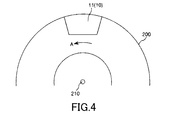
- FIG. 4 is a view for showing a state in which the brake pad of the present invention is arranged on a disk.
- FIG. 5 is a cross-sectional view showing another configuration example of the brake pad of the present invention.
- FIG. 1 and 2 are cross-sectional views each showing an example of the caliper device of the present invention.
- 1 and 2 are diagrams showing a state in which the caliper device is arranged on a disk.
- FIG. 1 is a diagram for illustrating a state where the braking of the disk is released
- FIG. 2 is a diagram for illustrating a state where the disk is braked by the caliper device.
- FIG. 3 is a plan view showing an embodiment of the brake pad of the present invention
- FIG. 4 is a view for showing a state in which the brake pad of the present invention is arranged on a disc
- FIG. It is sectional drawing which shows the other structural example of this brake pad.
- FIGS. 1 and 2 the upper side in FIGS. 1 and 2 is referred to as “upper” and the lower side is referred to as “lower”.
- the caliper device 100 shown in FIGS. 1 and 2 is used to brake a rotating (rotating) disc 200. As shown in FIGS. 1 and 2, the disk 200 rotates in the direction of arrow A with the rotation shaft 210 as the center axis of rotation.
- the caliper device 100 is installed in the vicinity of the disk 200.
- the caliper device 100 includes a caliper 50, a piston 30, and a brake pad 10.
- the caliper 50 corresponds to a casing that houses the piston 30, and has a space 40 that opens downward and a flow path 51 that communicates with the space 40, as shown in FIGS. 1 and 2.
- the space 40 has a cylindrical shape, and the piston 30 is accommodated in the space 40.
- An annular groove 55 is provided on the inner peripheral surface of the caliper 50 that defines the space 40.
- a ring-shaped sealing member 60 made of an elastic material is installed in the groove 55. The seal member 60 is pressed against the outer peripheral surface of the piston 30 so that the piston 30 can slide.
- one seal member 60 is installed in the space 40, but the number of seal members is not limited to this.
- two or more seal members may be arranged in the space 40 in the vertical direction in FIG.
- the number of seal members may be set as appropriate according to the use of the caliper device 100, required performance, and the like.
- sealing structure by such a sealing member 60 is not limited to the illustrated structure.
- the piston 30 has a function of pressing the brake pad 10 toward the disc 200.
- the piston 30 is accommodated in the space 40, and the seal member 60 is pressed against the outer peripheral surface of the piston 30. For this reason, the space 40 is liquid-tightly sealed by the seal member 60.
- the space 40 is filled with brake fluid.
- the caliper device 100 can supply brake fluid into the space 40 via the flow path 51 or flow out of the space 40 by a hydraulic device (not shown). By providing the seal member 60, it is possible to prevent leakage of brake fluid to the outside of the space 40 and entry of foreign matter into the space 40.
- the brake pad 10 is pressed against the disk 200 during braking and has a function of controlling the rotation of the disk 200 (reducing the rotation speed) by the frictional force generated between the brake pad 10 and the disk 200.
- the brake pad 10 is installed between the piston 30 and the disc 200.
- the brake pad 10 is composed of a joined body in which a back plate 11 and a friction material 12 are joined.
- the back plate 11 is located on the piston 30 side, and the friction material 12 is located on the disk 200 side.
- the upper surface of the back plate 11 is in contact with the lower surface of the piston 30. In addition, both may be joined or may not be joined. Further, the lower surface of the friction material 12 faces the upper surface of the disk 200.
- the caliper device of the present invention can be used for either an opposing device or a floating device.
- a control mechanism having the same configuration as the control mechanism including the space 40, the piston 30, and the brake pad 10 is provided via the center line 220 of the disk 200.
- a pair of control mechanisms including a space, a piston, and a brake pad are provided via the disk 200.
- both of the pair of brake pads move relative to the caliper 50 and brake the rotation of the disc 200 with the disc 200 interposed therebetween.
- the number of pairs of control mechanisms (the number of pairs) is not limited to one, and may be a plurality of pairs, for example, two, three, or the like.
- a brake pad having the same configuration as the brake pad 10 described above is disposed below the disc 200 via the center line 220 of the disc 200.
- the number of pairs of brake pads is not limited to one, and may be a plurality of sets such as two sets, three sets, and the like.
- the operation of the caliper device 100 will be described.
- the caliper device 100 is not braked (initial state)
- the lower surface of the friction material 12 is separated from the upper surface of the disk 200 with a slight gap.
- the brake fluid is supplied into the space 40 via the flow path 51 by the hydraulic device.
- the hydraulic pressure of the brake fluid in the space 40 increases, and the piston 30 moves to the disc 200 side.
- the brake pad 10 also moves downward in FIG. 1, and the friction material 12 is pressed against the disk 200 as shown in FIG.
- the rotation of the disk 200 is suppressed by the frictional force generated between the friction material 12 of the brake pad 10 and the disk 200.
- the supply of the brake fluid into the space 40 by the hydraulic device is stopped or the brake fluid is extracted from the space 40 through the flow path 51 to the hydraulic device.
- a part of the brake fluid in the space 40 flows out of the space 40 through the flow path 51, and the pressure (hydraulic pressure) of the brake fluid on the piston 30 is reduced.
- the force which presses piston 30 to the disk 200 side decreases, and seal member 60 tries to restore to the state at the time of non-braking by the restoring force.
- the piston 30 moves in a direction away from the disk 200 (upward).
- the lower surface of the friction material 12 is separated from the upper surface of the disk 200, or the pressure contact force between the lower surface of the friction material 12 and the upper surface of the disk 200 decreases.
- the braking of the disc 200 is released.
- the piston and the brake pad which are arranged to face each other via the center line 220 of the disc 200, are similar to the above-described operation both at the time of braking and at the time of braking release. Operate.
- the disc 200 is sandwiched by at least one pair of brake pads at the time of braking, so that a larger braking force can be obtained.
- braking is performed with the disc 200 sandwiched between the brake pad 10 movable with respect to the caliper 50 and the brake pad fixed to the caliper 50. That is, when the movable brake pad 10 is pressed against the disc 200, the caliper 50 moves in a direction away from the disc 200 (upward) by the reaction force. Due to the upward movement of the caliper 50, a brake pad (not shown) arranged opposite to the brake pad 10 and fixed to the caliper 50 moves upward, that is, in a direction approaching the disk 200. Pressed. As a result, the disc 200 is sandwiched between the movable brake pad 10 and the fixed brake pad, and braking is performed.
- the use of the caliper device of the present invention is not particularly limited, and can be used, for example, for aircraft, automobiles (vehicles), motorcycles, bicycles, railway vehicles, elevators, robots, construction machines, agricultural machines, other industrial machines, and the like.
- the brake pad of the present invention is pressed against the disk during braking and can control the rotation of the disk by a frictional force generated between the brake pad and the disk.
- the brake pad 10 is composed of a joined body in which the back plate 11 and the friction material 12 are joined.
- the back plate 11 and the friction material 12 may be bonded or fused (welded), and the back plate 11 and the friction material 12 may be integrated.
- the interface between the back plate 11 and the friction material 12 is clearly shown, but the interface between the back plate 11 and the friction material 12 may not be clear.
- these materials may exist in the vicinity of the interface between the back plate 11 and the friction material 12 in a mixed state.
- the vicinity of the interface between the back plate 11 and the friction material 12 may be made of a material (a so-called gradient material) in which some of these components are sequentially changed in the thickness direction.
- the planar shape of the brake pad 10 (the friction material 12 and the back plate 11) is substantially rectangular as shown in FIG.
- the friction material 12 is smaller than the back plate 11 in a plan view, and is positioned so as to be included in the back plate 11 in a plan view.
- planar shapes of the friction material 12 and the back plate 11 are substantially quadrangular, but are not limited thereto.
- the planar shape of the friction material 12 and the back plate 11 may be, for example, a substantially circular shape or a polygonal shape. Further, these planar shapes may be different from each other. In addition, what is necessary is just to set these planar shapes suitably according to the use of the brake pad 10. FIG.
- the friction material 12 and the back plate 11 constituting the brake pad 10 will be sequentially described.
- the friction material comes into contact with the disk during braking, and has a function of suppressing the rotation of the disk by friction caused by the contact.
- the friction material 12 abuts on the disk 200 during braking, and generates frictional heat due to friction generated between the friction material 12 and the disk 200. Therefore, it is preferable that the constituent material of the friction material 12 is excellent in heat resistance so that it can cope with frictional heat during braking.
- the specific constituent material is not particularly limited.
- a fiber material such as rock wool, Kevlar fiber, copper fiber, a binder material such as resin, barium sulfate, zirconium silicate, cash dust, And a mixture containing a filler such as graphite.
- the average thickness of the friction material 12 is not particularly limited, but is preferably 3 mm to 15 mm, more preferably 5 mm to 12 mm.
- the average thickness of the friction material 12 is less than the lower limit value, depending on the material constituting the friction material 12, the mechanical strength is reduced, so that damage is likely to occur and the life may be shortened.
- the caliper apparatus 100 whole provided with the friction material 12 may enlarge a little.
- the back plate of the present invention is hard and has high mechanical strength. For this reason, the back plate is hard to be deformed, and can reliably support the friction material, and can uniformly transmit the pressing force of the piston to the friction material during braking. In addition, the back plate of the present invention can make it difficult to transmit the frictional heat and vibration generated when the friction material slides into contact with the disk during braking.
- the back plate 11 is composed of a back plate composition containing a resin, a plurality of first fibers, and a plurality of second fibers.
- the back plate composition includes a resin, a plurality of first fibers, and a plurality of second fibers.
- composition for back board contains resin.
- the resin may be in any form such as solid, liquid, semi-solid, etc. at room temperature.
- the resin examples include curable resins such as thermosetting resins, photocurable resins, reactive curable resins, and anaerobic curable resins.
- curable resins such as thermosetting resins, photocurable resins, reactive curable resins, and anaerobic curable resins.
- a thermosetting resin is particularly preferable because of excellent mechanical properties such as linear expansion coefficient and elastic modulus after curing.
- thermosetting resin examples include phenol resin, epoxy resin, bismaleide resin, urea (urea) resin, melamine resin, polyurethane resin, cyanate ester resin, silicone resin, oxetane resin, (meth) acrylate resin, unsaturated polyester resin.
- Diallyl phthalate resin, polyimide resin, benzoxazine resin and the like, and one or more of them can be used in combination.
- a thermosetting resin especially as a thermosetting resin, a phenol resin, an epoxy resin, a bismaleide resin, a benzoxazine resin, and an unsaturated polyester resin are preferable, and a phenol resin is more preferable.
- the back plate 11 can exhibit particularly excellent heat resistance against frictional heat generated when the friction material 12 comes into contact with the disk 200 during braking.
- the phenol resin examples include novolak type phenol resins such as phenol novolak resin, cresol novolak resin, bisphenol A novolak resin, arylalkylene type novolak resin; unmodified resole phenol resin, tung oil, linseed oil, walnut oil
- resol-type phenol resins such as oil-modified resol phenol resins, and one or more of them can be used in combination.
- the phenol resin a phenol novolac resin is particularly preferable. Thereby, while being able to manufacture the backplate 11 with low cost and high dimensional accuracy, the obtained backplate 11 can exhibit the especially outstanding heat resistance.
- the weight average molecular weight of the phenol resin is not particularly limited, but is preferably about 1,000 to 15,000. If the weight average molecular weight is less than the lower limit, it may be difficult to prepare the composition for the back plate because the viscosity of the resin is too low, and if the upper limit is exceeded, the melt viscosity of the resin increases. In some cases, the moldability of the back plate composition is lowered.
- the weight average molecular weight of the phenol resin is measured by, for example, gel permeation chromatography (GPC) and can be defined as a weight molecular weight in terms of polystyrene.
- Epoxy resins include bisphenol A type epoxy resins, bisphenol F type epoxy resins, bisphenol AD type epoxy resins and other bisphenol type epoxy resins; phenol novolac type epoxy resins, cresol novolak type epoxy resins and other novolak type epoxy resins; brominated bisphenols Brominated epoxy resins such as A-type epoxy resins and brominated phenol novolac-type epoxy resins; biphenyl-type epoxy resins; naphthalene-type epoxy resins; tris (hydroxyphenyl) methane-type epoxy resins, etc., one of these Alternatively, two or more kinds can be used in combination.
- the epoxy resin bisphenol A type epoxy resin, phenol novolak type epoxy resin, and cresol novolak type epoxy resin having a relatively low molecular weight are particularly preferable.
- the epoxy resin is preferably a phenol novolac type epoxy resin or a cresol novolac type epoxy resin, and particularly preferably a tris (hydroxyphenyl) methane type epoxy resin.
- the bismaleimide resin is not particularly limited as long as the resin has maleimide groups at both ends of the molecular chain, but a resin having a phenyl group is more preferable.
- a resin having a phenyl group is more preferable.
- the bismaleimide resin for example, a resin represented by the following formula (1) can be used.
- the bismaleimide resin may have maleimide groups that bind to positions other than both ends of the molecular chain.
- R 1 to R 4 are hydrogen or a substituted or unsubstituted hydrocarbon group having 1 to 4 carbon atoms
- R 5 is a divalent substituted or unsubstituted organic group.
- the organic group is a hydrocarbon group that may contain a heteroatom, and examples of the heteroatom include O, S, and N.
- R 5 is preferably a hydrocarbon group having a main chain in which a methylene group, an aromatic ring, and an ether bond (—O—) are bonded in any order, and more preferably methylene bonded in any order in the main chain
- a substituent and / or a side chain may be bonded, and specific examples thereof include, for example, a hydrocarbon group having 3 or less carbon atoms, a maleimide group, a phenyl group, and the like. It is done.
- the bismaleimide resin for example, N, N ′-(4,4′-diphenylmethane) bismaleimide, bis (3-ethyl-5-methyl-4-maleimidophenyl) methane, 2,2- Bis [4- (4-maleimidophenoxy) phenyl] propane, m-phenylenebismaleimide, p-phenylenebismaleimide, 4-methyl-1,3-phenylenebismaleimide, N, N′-ethylenedimaleimide, N, N '-Hexamethylene dimaleimide and the like can be mentioned, and one or more of these can be used in combination.
- N, N ′-(4,4′-diphenylmethane) bismaleimide bis (3-ethyl-5-methyl-4-maleimidophenyl) methane, 2,2- Bis [4- (4-maleimidophenoxy) phenyl] propane, m-phenylenebismaleimide, p-phenylenebismaleimide, 4-
- the content of the resin in the composition for the back plate is not particularly limited, but is preferably 20% by mass to 80% by mass, and more preferably 30% by mass to 50% by mass.
- the resin content is less than the lower limit, depending on the type of resin, the binding strength with other materials (particularly, the first fiber and the second fiber) constituting the back plate composition is sufficient. May not be obtained.
- the content rate of resin exceeds the said upper limit, the quantity of the 1st fiber and 2nd fiber which are mentioned later reduces relatively, and the effect of including a 1st fiber and a 2nd fiber May not be fully demonstrated.
- the back plate composition includes a plurality of first fibers and a plurality of second fibers.
- the composition for back plate includes a first fiber group that is an aggregate of a plurality of first fibers and a second fiber group that is an aggregate of a plurality of second fibers.
- the average length of the first fibers belonging to the first fiber group is longer than the average length of the second fibers belonging to the second fiber group (in other words, the second fibers belonging to the second fiber group).
- the average length of the first fibers is shorter than the average length of the first fibers belonging to the first fiber group).
- the back plate composition includes two kinds of fibers having different average lengths, so that the moldability (ease of forming) is improved, and the formed back plate 11 has dimensional accuracy and Increases mechanical strength.
- the first fiber and the second fiber will be described in detail.
- L2 / L1 satisfies the relationship of 0.001 to 0.5. It is more preferable to satisfy the relationship of 0.01 to 0.4, and it is more preferable to satisfy the relationship of 0.015 to 0.3.
- the back plate composition has improved moldability, The back plate 11 has particularly high dimensional accuracy and mechanical strength.
- the first fibers having a longer fiber length than the second fibers mainly ensure the mechanical strength of the back plate 11 and the back plate 11. Contributes to shape stability.
- the second fiber having a short fiber length also contributes to the shape stability of the back plate 11, but mainly fills the space between the first fibers having a relatively long fiber length (interpolated). ) Take a role. That is, the second fiber enters the gap between the first fibers, thereby increasing the mechanical strength of the back plate 11 in the portion where the first fibers do not exist, that is, the effect of reinforcing the effect of the first fibers. (Reinforcing action) is demonstrated. More specifically, the first fiber has a high tendency to be oriented along the surface direction of the back plate 11 because of its length.
- the second fibers enter the first fibers, but the second fibers are oriented along the surface direction of the back plate 11 and along a direction different from the surface direction of the back plate 11. However, it tends to be oriented. Thus, since the orientation state of the first fiber and the second fiber is different, both the first fiber and the second fiber have sufficient mechanical strength and shape stability in a small amount in the back plate 11. Can be granted.
- the above functions are particularly prominent when the L2 / L1 is within the above range. Furthermore, when the first fiber and the second fiber are made of the same or the same material, this tendency is remarkable.
- the average length L1 of the first fibers is preferably 5 mm to 50 mm, and more preferably 8 mm to 12 mm.
- the shape stability of the back plate 11 may not be sufficiently obtained depending on the constituent material of the first fibers and the content thereof.
- the average length L1 of the first fibers exceeds the upper limit, the fluidity of the back plate composition may not be sufficiently obtained when the back plate 11 is molded.
- the average length L2 of the second fibers is preferably 50 ⁇ m to 10 mm, more preferably 150 ⁇ m to 5 mm, and further preferably 200 ⁇ m to 3 mm.
- the average length L2 of the second fibers is less than the lower limit value, for example, when the content ratio of the first fibers is small, in order to increase the reinforcing action of the effect by the first fibers, It may be necessary to relatively increase the content of the second fiber in the composition.
- the average length L2 of the second fibers exceeds the upper limit, when the content of the first fibers is large, the ratio of the second fibers entering the gaps of the first fibers is descend.
- the average diameter D1 of the first fibers is preferably 5 ⁇ m to 20 ⁇ m, more preferably 6 ⁇ m to 18 ⁇ m, and even more preferably 7 ⁇ m to 16 ⁇ m.
- the average diameter D1 of the first fibers is less than the lower limit value, the first fibers are likely to be damaged when the back plate 11 is formed, depending on the constituent material and content of the first fibers.
- the average diameter D1 of the first fibers exceeds the upper limit, unevenness may occur in the strength at locations where the first fibers are relatively large and relatively small in the back plate 11.
- the average diameter D2 of the second fibers is preferably 5 ⁇ m to 20 ⁇ m, more preferably 6 ⁇ m to 18 ⁇ m, and even more preferably 7 ⁇ m to 16 ⁇ m.
- the second fibers are likely to be damaged during the molding of the back plate 11 depending on the constituent materials and the content ratios of the first fibers and the second fibers.
- the average diameter D2 of the second fibers exceeds the upper limit, the second fibers are less likely to enter the gaps of the first fibers depending on the content of the first fibers.
- the cross-sectional shape of the first fiber is not particularly limited, but may be any shape such as a substantially circular shape such as a circle and an ellipse, a polygon such as a triangle, a quadrangle, and a hexagon, a flat shape, and a deformed shape such as a star. Also good.
- the cross-sectional shape of the first fiber is particularly preferably substantially circular or flat. Thereby, the smoothness of the surface of the back plate 11 can be improved.
- the cross-sectional shape of the second fiber is not particularly limited, but may be any shape such as a substantially circular shape such as a circle and an ellipse, a polygon such as a triangle and a rectangle, a flat shape, and a deformed shape such as a star.
- the cross-sectional shape of the second fiber is particularly preferably substantially circular or flat.
- the first fiber may be present alone in the back plate composition, or may be present as a fiber bundle in which some of the first fibers are densely integrated.
- the fiber bundle may be in any state such as a stranded wire shape, a straight line shape, or a mesh shape. The same applies to the second fiber.
- first fiber and the second fiber for example, organic fiber such as aramid fiber, acrylic fiber, nylon fiber (aliphatic polyamide fiber) and phenol fiber, glass fiber, carbon fiber, ceramic fiber, rock wool, examples include inorganic fibers such as potassium titanate fiber and basalt fiber, metal fibers such as stainless steel fiber, steel fiber, aluminum fiber, copper fiber, brass fiber and bronze fiber, and a combination of one or more of these. Can be used.
- the first fiber and the second fiber are more preferably aramid fiber, carbon fiber, and glass fiber, respectively, and at least one of the first fiber and the second fiber is glass. More preferably, it is a fiber.
- the uniformity of the back plate composition per unit volume is improved, and the moldability of the back plate composition is particularly good. Furthermore, by improving the uniformity of the back plate composition, the uniformity of the internal stress in the formed back plate 11 is improved, and as a result, the waviness of the back plate 11 is reduced. Moreover, the abrasion resistance of the back plate 11 under a high load can be further improved. Further, when carbon fiber or aramid fiber is used, the mechanical strength of the back plate 11 can be further increased, and the back plate 11 can be further reduced in weight.
- the glass constituting the glass fiber include, for example, E glass, C glass, A glass, S glass, D glass, NE glass, T glass, and H glass.
- E glass, T glass, or S glass is particularly preferable.
- the carbon fiber include, for example, a high-strength carbon fiber having a tensile strength of 3500 MPa or more and a high-modulus carbon fiber having an elastic modulus of 230 GPa or more.
- the carbon fiber may be either a polyacrylonitrile (PAN) -based carbon fiber or a pitch-based carbon fiber, but is preferably a polyacrylonitrile-based carbon fiber because of its high tensile strength.
- PAN polyacrylonitrile
- the aramid resin constituting the aramid fiber may have either a meta-type structure or a para-type structure.
- the first fiber and the second fiber may be made of different materials, but are preferably made of the same or the same kind of material.
- the first fiber and the second fiber have close mechanical strength, and the composition for the back plate is adjusted. The handling is improved.
- the same type means that, for example, if the first fiber is a glass fiber, the second fiber is also a glass fiber, and the type of glass such as E glass or C glass. These differences are included in the “same kind” range.
- both the first fiber and the second fiber are not only glass fibers but also the first fibers are fibers composed of E glass.
- the second fiber is also a fiber composed of E glass.
- the first fiber and the second fiber are particularly preferably an aramid fiber, a carbon fiber, and a glass fiber. More preferably.
- both the first fiber and the second fiber are glass fibers, their mechanical strengths are close to each other, and handling properties when adjusting the composition for the back plate are improved.
- both the first fiber and the second fiber can enjoy the advantages of the glass fiber described above, the fluidity of the back plate composition is further improved, and the moldability thereof is particularly good. .
- the glass type is particularly preferably E glass.
- At least one of the first fiber and the second fiber is surface-treated in advance.
- the first fiber and / or the second fiber can increase the dispersibility in the composition for the back plate, increase the adhesion with the resin, and the like.
- Examples of such surface treatment methods include coupling agent treatment, oxidation treatment, ozone treatment, plasma treatment, corona treatment, and blast treatment, and one or more of these may be combined. Can be used. Among these, a coupling agent treatment is particularly preferable as the surface treatment method.
- the coupling agent used for the coupling agent treatment is not particularly limited, and can be appropriately selected depending on the type of resin.
- coupling agents include silane coupling agents, titanium coupling agents, and aluminum coupling agents, and one or more of these can be used in combination.
- a silane coupling agent is particularly preferable as the coupling agent.
- the first fiber and / or the second fiber have particularly improved adhesion to the curable resin.
- Silane coupling agents include epoxy silane coupling agents, cationic silane coupling agents, amino silane coupling agents, vinyl silane coupling agents, mercapto silane coupling agents, methacryl silane coupling agents, chlorosilane coupling agents, and acrylic silanes. A coupling agent etc. are mentioned.
- the first fibers and the second fibers may be oriented along the thickness direction of the back plate 11, for example, or may be oriented along the surface direction of the back plate 11. Further, the back plate 11 may be oriented while being inclined at a predetermined angle with respect to the thickness direction or the plane direction of the back plate 11 or may not be oriented (non-oriented). However, at least the first fiber of the first fiber and the second fiber is preferably oriented along the surface direction of the back plate 11. Thereby, the dimensional change along the surface direction of the back plate 11 can be further reduced. As a result, deformation such as warping of the back plate 11 can be more reliably suppressed or prevented. Note that the first fiber or the second fiber is oriented along the surface direction of the back plate 11 means that the first fiber or the second fiber is oriented substantially parallel to the surface of the back plate 11. It means the state of being.
- the back plate 11 is disposed with respect to the disc 200 as shown in FIG.
- the first fiber and / or the second fiber may be oriented in a random direction in the plane, or may be oriented along the radial direction of the disk 200, and in the traveling direction A of the disk 200. It may be oriented along, or may be oriented along an intermediate direction (predetermined direction) between them.
- the bending strength and compressive strength of the back plate 11 are uniform in all directions in the plane. Get higher.
- the first fiber or the second fiber is oriented along the traveling direction A of the disk 200 that is braked by the brake pad 10.
- the first fiber or the second fiber is the surface of the back plate 11. It is oriented along the direction and oriented substantially parallel along the traveling direction A of the disk 200.
- the total content of the first fibers and the second fibers in the back plate composition is preferably 20% by mass to 80% by mass, and more preferably 30% by mass to 70% by mass. preferable.
- the mechanical strength of the back plate 11 may be lowered depending on the materials of the first fiber and the second fiber. is there.
- the total content rate of a 1st fiber and a 2nd fiber exceeds the said upper limit, the fluidity
- the content ratio of the first fiber is X1 [mass%] and the content ratio of the second fiber is X2 [mass%]
- X2 / X1 satisfies the relationship of 0.05 to 1. It is more preferable to satisfy the relationship of 1 to 0.25.
- the ratio X2 / X1 of the content ratio of the first fiber and the content ratio of the second fiber is less than the lower limit value, when the length of the first fiber is relatively long, when the back plate 11 is manufactured, Damage or the like is likely to occur in the first fiber.
- the ratio X2 / X1 between the content ratio of the first fibers and the content ratio of the second fibers exceeds the upper limit value, if the length of the first fibers is relatively short, the machine of the back plate 11 Strength may decrease. Further, when the first fiber and the second fiber are made of the same or the same material, these tendencies appear remarkably.
- the content of the first fiber is preferably 35% by mass to 80% by mass, more preferably 40% by mass to 75% by mass, and further preferably 50% by mass to 65% by mass.
- the content rate of the first fiber is less than the lower limit, depending on the length of the first fiber and the content rate of the second fiber, the shrinkage rate at the time of molding the back plate 11 may be slightly increased. is there.
- the content rate of the 1st fiber exceeds the upper limit, depending on the length of the 1st fiber and the content rate of the 2nd fiber, breakage of the 1st fiber, etc. at the time of manufacture of back board 11 etc. May be more likely to occur.
- the content of the second fiber is preferably 2% by mass to 40% by mass, more preferably 3% by mass to 35% by mass, and further preferably 5% by mass to 30% by mass.
- the content rate of the second fiber is less than the lower limit value, the mechanical properties of the back plate 11 may not be sufficiently obtained depending on the length of the second fiber and the content of the first fiber.
- the content rate of a 2nd fiber exceeds the said upper limit, the fluidity
- the back plate composition is one or more.
- the third fiber or the like may be included.
- composition for the back plate may further comprise a curing agent, a curing aid, a filler, a release agent, a pigment, a sensitizer, an acid proliferating agent, a plasticizer, a flame retardant, a stabilizer, and an antioxidant, as necessary And may contain an antistatic agent or the like.
- curing agent can be suitably selected and used according to the kind etc. of resin, and is not limited to a specific compound.
- the curing agent can be selected from bifunctional or higher epoxy compounds, isocyanates, hexamethylenetetramine, and the like.
- the curing agent may be an acid anhydride such as an amine compound such as an aliphatic polyamine, aromatic polyamine or diciamine diamide, an alicyclic acid anhydride, or an aromatic acid anhydride.
- an acid anhydride such as an amine compound such as an aliphatic polyamine, aromatic polyamine or diciamine diamide, an alicyclic acid anhydride, or an aromatic acid anhydride.
- products polyphenol compounds such as novolac type phenol resins, imidazole compounds and the like.
- the content of the curing agent in the composition for the back plate is appropriately set depending on the type of curing agent and resin used, and is, for example, 0.1% by mass to 30% by mass. It is preferable. Thereby, the back board 11 can be easily formed in arbitrary shapes.
- the curing aid is not particularly limited, and for example, an imidazole compound, a tertiary amine compound, an organic phosphorus compound, or the like can be used.
- the content of the curing aid in the composition for the back plate is appropriately set depending on the type of the curing aid and the curing agent to be used. For example, 0.001% by mass to 10% Mass% is preferred. Thereby, since the composition for back boards can be hardened more easily, the back board 11 can be shape
- the filler is not particularly limited, and examples thereof include inorganic fillers and organic fillers.
- examples of the inorganic filler include calcium carbonate, clay, silica, mica, talc, wollastonite, glass beads, milled carbon, graphite, and the like, and one or more of these may be used in combination.
- examples of the organic filler include polyvinyl butyral, acrylonitrile butadiene rubber, pulp, wood powder, and the like, and one or more of these can be used in combination.
- acrylonitrile butadiene rubber is preferably used as the filler (organic filler) from the viewpoint that the effect of improving the toughness of the back plate 11 (molded product) is further enhanced.
- the content of the filler in the back plate composition is not particularly limited, but is preferably 1% by mass to 30% by mass. Thereby, the mechanical strength of the back plate 11 can be further improved.
- the release agent is not particularly limited, but zinc stearate, calcium stearate and the like can be used.
- the content of the release agent in the back plate composition is not particularly limited, but is preferably 0.01% by mass to 5.0% by mass. Thereby, the back board 11 can be easily formed in arbitrary shapes.
- the average thickness of the back plate 11 is not particularly limited, but is preferably 2 mm to 12 mm, more preferably 3 mm to 10 mm, and still more preferably 4 mm to 8 mm. If the thickness of the back plate 11 is less than the lower limit, the heat resistance of the back plate 11 against frictional heat generated during braking may be slightly lowered depending on the type of resin. In addition, when the thickness of the back plate 11 exceeds the upper limit, the entire caliper device 100 including the brake pad 10 is slightly increased in size.
- composition for the back plate for example, a powder impregnation method using roving in accordance with the description in JP-T-2002-509199 can be used.
- the powder impregnation method using roving is a method of coating the first fiber and the second fiber by a dry method using a fluidized bed technique. Specifically, first, other materials constituting the back plate composition other than the first fibers and the second fibers are directly mixed from the fluidized bed without prior kneading. Adhere to the fiber. Next, another material is fixed to the first fiber and the second fiber by heating for a short time. The first and second fibers thus coated are then passed through a conditioning section consisting of a cooling device and optionally a heating device. Thereafter, the cooled and coated first and second fibers are taken up and cut to a desired length by a strand cutter. Then, the composition for back boards can be prepared by mixing the 1st fiber cut
- examples of the method for forming the back plate 11 include compression molding, transfer molding, and injection molding.
- Compressive molding can weaken the degree of orientation of the first fiber and / or the second fiber during molding. For this reason, the anisotropy in the back plate 11 can be reduced with respect to physical properties such as strength distribution, molding shrinkage, and linear expansion. Moreover, compression molding can be used suitably when shape
- the size of the back plate 11 to be molded can be controlled with higher accuracy by transfer molding.
- transfer molding can be suitably used to manufacture the back plate 11 having a complicated shape or the back plate 11 requiring high dimensional accuracy.
- Transfer molding can also be suitably applied to insert molding.
- the molding cycle of the back plate 11 can be further shortened by injection molding. For this reason, the mass productivity of the back plate 11 can be improved.
- the injection molding can be suitably used for the back plate 11 having a complicated shape.
- the back plate composition is injected at a high speed, the first fibers in the back plate 11 and the first fibers in the back plate 11 can be increased in degree of orientation of the first fibers and the second fibers in the back plate 11 and the like. Control of the orientation state of the second fiber can be performed with higher accuracy.
- the method for manufacturing the brake pad 10 is not particularly limited, and examples thereof include a method of pasting the friction material 12 after the back plate 11 is formed, a method of integrally forming the back plate 11 and the friction material 12, and the like. .
- the friction material side surface of the back plate is configured as a flat surface, and the interface between the back plate and the friction material is linear in the longitudinal section of the brake pad.
- the configuration of the surface is not limited to this.
- a plurality of ridges (convex portions) are formed on the surface of the back plate on the friction material side, and the interface between the back plate and the friction material is uneven in the longitudinal section of the brake pad. May be. This further improves the bondability between the back plate and the friction material.
- the brake pad is configured by a single-layer back plate and a single-layer friction material, but the configuration of the brake pad is not limited to this.
- the back plate may be composed of a multilayer laminate
- the friction material may be composed of a multilayer laminate
- both the back plate and the friction material may be composed of a multilayer laminate.
- the friction material has a substantially uniform thickness, but is not limited to this, and may have portions having different thicknesses.
- the friction material may have a slit formed along its thickness direction.
- composition for back plate A composition for a back plate was prepared as follows. [1-1] Preparation of First Fiber Coated with Resin Mixture First, glass fiber (glass fiber roving 1084 manufactured by PPG Co., Ltd.) subjected to surface treatment with a silane coupling agent as a fibril of the first fiber. 55% by mass was prepared for an average diameter of 15 ⁇ m).
- phenol resin as resin Suditite Resin PR-51470 manufactured by Sumitomo Bakelite Co., Ltd., weight average molecular weight: 2800
- hexamethylenetetramine as curing agent 6.0% by mass of hexamethylenetetramine as curing agent.
- a resin mixture is obtained by mixing 1.0% by mass of magnesium oxide as an auxiliary agent, 1.0% by mass of calcium stearate as a release agent, and 1.0% by mass of carbon black as a pigment. It was.
- the obtained resin mixture was coated on the surface-treated glass fiber using a fluidized bed technique, melted and fixed by a heater heated to 400 ° C., and then cooled.
- the glass fiber coated with the resin mixture was cut with a strand cutter so as to obtain first fibers having an average length shown in Table 2. As a result, a first fiber coated with the resin mixture was obtained.
- phenol resin as resin Suditite Resin PR-51470 manufactured by Sumitomo Bakelite Co., Ltd., weight average molecular weight: 2800
- hexamethylenetetramine as curing agent 6.0% by mass of hexamethylenetetramine as curing agent.
- a resin mixture is obtained by mixing 1.0% by mass of magnesium oxide as an auxiliary agent, 1.0% by mass of calcium stearate as a release agent, and 1.0% by mass of carbon black as a pigment. It was.
- the obtained resin mixture was coated on the surface-treated glass fiber using a fluidized bed technique, melted and fixed by a heater heated to 400 ° C., and then cooled.
- the glass fiber coated with the resin mixture was cut with a strand cutter so that second fibers having an average length shown in Table 2 were obtained. As a result, a second fiber coated with the resin mixture was obtained.
- the first fiber and the second fiber are oriented in the surface direction of the back plate and along the traveling direction of the disc.
- the composition was charged and compressed by a conventional method to prepare a preform.
- the preform had a length of 110 mm, a width of 45 mm, a height of 8 mm, and a weight of 60 g.
- the preform was preheated to 100 to 110 ° C. by a parallel plate type high frequency preheater.
- the preheated preform is put into a mold so that the first fiber and the second fiber are aligned along the surface direction of the back plate and are aligned along the disk traveling direction within the surface.
- it was pressurized and cured by heating to obtain a back plate having a shape shown in FIG. 3 (schematic dimensions: length 130 mm ⁇ width 50 mm ⁇ thickness 6 mm with respect to the traveling direction of the disk).
- the molding conditions were a mold temperature of 170 to 180 ° C., a molding pressure of 20 to 25 MPa, and a curing time of 3 minutes.
- Example 2 Back plate in the same manner as in Example 1 except that the composition of the back plate composition was changed as shown in Table 1 and the first and second fibers were changed as shown in Table 2. Manufactured.
- Example 10 The composition of the back plate composition was changed as shown in Table 1, the adjustment of the second fiber coated with the resin mixture was changed as follows, and the composition of the first fiber and the second fiber was changed to Table 2.
- a back plate was produced in the same manner as in Example 1 except that the change was made as shown in FIG.
- phenol resin as resin Suditite Resin PR-51470 manufactured by Sumitomo Bakelite Co., Ltd., weight average molecular weight: 2800
- hexamethylenetetramine as curing agent 6.0% by mass of hexamethylenetetramine as curing agent.
- a resin mixture is obtained by mixing 1.0% by mass of magnesium oxide as an auxiliary agent, 1.0% by mass of calcium stearate as a release agent, and 1.0% by mass of carbon black as a pigment. It was.
- the surface-treated glass fiber and the obtained resin mixture were roll-kneaded for 3 minutes, cooled, and then pulverized into granules by a pulverizer. .
- the average length of the obtained second fiber is as follows: It measured by the method of. A sample collected from the second fiber was ashed in an electric furnace at 400 ° C. for 9 hours, and the ashed second fiber was dispersed in acetone. A part of the dispersion was transferred to a slide glass, an image was taken at a low magnification with an optical microscope, and the fiber length of each second fiber was measured.
- Example 11 Back plate was made in the same manner as in Example 10 except that the composition of the composition for the back plate was changed as shown in Table 1, and the structure of the first fiber and the second fiber was changed as shown in Table 2. Manufactured.
- Example 13 The composition of the composition for the back plate is changed as shown in Table 1, the kneading time by the heating roll is changed to 6 minutes in the adjustment of the second fiber, and the composition of the first fiber and the second fiber is shown in Table 2.
- a back plate was produced in the same manner as in Example 10 except that the changes were made as shown in FIG.
- the first fiber and the second fiber are oriented along the surface direction of the back plate, but the back surface is oriented in a random direction within the surface.
- plate was thrown in and it compressed by the conventional method, and produced the preform.
- the preform had a length of 110 mm, a width of 45 mm, a height of 8 mm, and a weight of 60 g.
- the preform was preheated to 100 to 110 ° C. by a parallel plate type high frequency preheater.
- the preheated preform has the first fiber and the second fiber oriented along the surface direction of the back plate, but is put into a mold so that it faces a random direction within the surface, and is pressurized and heated. Curing was performed to obtain a back plate having a shape shown in FIG. 3 (schematic dimensions: length 130 mm ⁇ width 50 mm ⁇ thickness 6 mm with respect to the traveling direction of the disk).
- the molding conditions were a mold temperature of 170 to 180 ° C., a molding pressure of 20 to 25 MPa, and a curing time of 3 minutes.
- Example 1 A back plate was produced in the same manner as in Example 1 except that the composition of the back plate composition was changed as shown in Table 1 without using the first fiber and the second fiber.
- Example 2 A back plate was produced in the same manner as in Example 1 except that the composition of the back plate composition was changed as shown in Table 1 without using the second fibers.
- Example 3 A back plate was produced in the same manner as in Example 1 except that the composition of the back plate composition was changed as shown in Table 1 without using the first fiber.
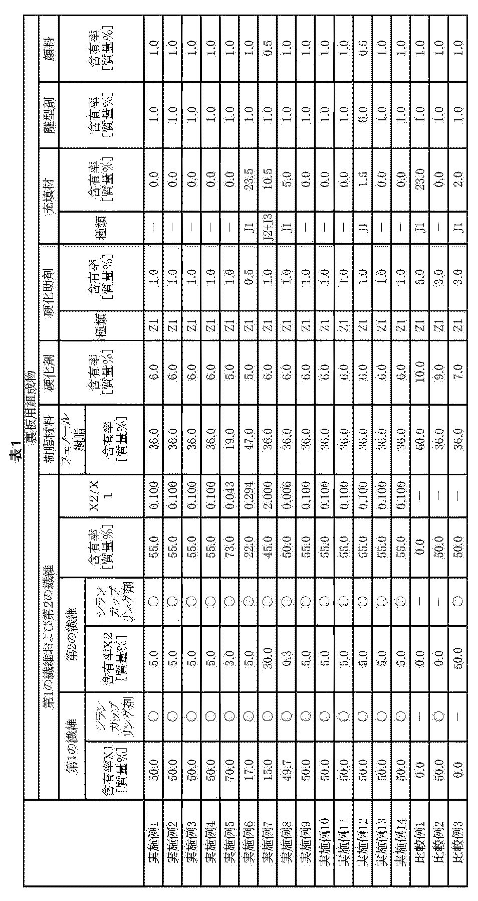
- Table 1 shows the composition and the like of the composition for the back plate of each Example and each Comparative Example
- Table 2 shows the composition of the first fiber and the second fiber
- Table 3 constitutes the back plate. It showed about the orientation state of the 1st fiber and the 2nd fiber.
- the first fiber obtained from glass fiber is “glass 1”
- carbon fiber Toho Tenax Co., Ltd. carbon fiber roving HTS40, average diameter D1). : 7 ⁇ m) as the first fiber obtained from “Carbon 1”
- the second fiber obtained from the glass fiber PPG glass fiber roving 1084, average diameter D2: 15 ⁇ m) as “Glass 2”.
- second fiber obtained from “glass 3”, carbon fiber (Toho Tenax Co., Ltd.
- the second fiber obtained from is “carbon 2”, magnesium oxide as a curing aid is “Z1”, and cured.
- Z2 is 2-methylimidazole as an auxiliary
- J1 is clay as a filler
- J2 is milled carbon as a filler
- J3 is graphite as a filler
- the second fibers are oriented along the surface direction of the back plate and in the plane along the direction of movement of the disc, the “travel direction”, the first in the back plate A state in which the fibers and the second fibers are oriented along the surface direction of the back plate but are oriented in a random direction within the surface is indicated as “surface direction”.
- A The filling property of the composition for a back plate into the portion corresponding to the ear portion of the mold is good, and the appearance of the formed ear portion is also good.
- B The filling property of the composition for the back plate into the portion corresponding to the ear portion of the mold is good, but the surface of the formed ear portion is partially rough.
- C The filling property of the composition for the back plate into a portion corresponding to the ear portion of the mold is poor, and a fatal defect in appearance such as gas sprinkling is observed in the formed ear portion.
- the composition for the back plate of each example according to the present invention has good moldability, and the obtained backing has a sufficiently high bending strength with a low linear expansion coefficient, It had a flexural modulus and compressive strength. On the other hand, in the comparative example, a satisfactory result was not obtained.
- the average length of the first fibers includes a resin, a plurality of first fibers, and a plurality of second fibers whose average length is shorter than the average length of the first fibers.
- Is L1 [ ⁇ m] and the average length of the second fibers is L2 [ ⁇ m]
- L2 / L1 satisfies the relationship of 0.001 to 0.5. It is possible to provide a back plate composition that can form a back plate to be bonded to a friction material of a brake pad having excellent mechanical strength. Therefore, the present invention has industrial applicability.
Landscapes
- Engineering & Computer Science (AREA)
- General Engineering & Computer Science (AREA)
- Mechanical Engineering (AREA)
- Braking Arrangements (AREA)
- Reinforced Plastic Materials (AREA)
Abstract
Description
(1) 摩擦材と、前記摩擦材に接合された裏板とを備えるブレーキパッドの、前記裏板を形成するための裏板用組成物であって、
樹脂と、複数本の第1の繊維と、平均長さが前記第1の繊維の平均長さより短い複数本の第2の繊維とを含み、
前記第1の繊維の平均長さをL1[μm]とし、前記第2の繊維の平均長さをL2[μm]としたとき、L2/L1が0.001~0.5の関係を満足することを特徴とする裏板用組成物。
前記摩擦材に接合された上記(10)ないし(12)のいずれかに記載の前記裏板とを備えることを特徴とするブレーキパッド。
[キャリパ装置]
図1および図2は、それぞれ、本発明のキャリパ装置の一例を示す断面図である。図1および図2は、それぞれ、キャリパ装置をディスクに配置した状態を示す図である。これらのうち、図1は、ディスクの制動が解除されている状態を示すための図であり、図2は、キャリパ装置により、ディスクが制動されている状態を示すための図である。また、図3は、本発明のブレーキパッドの実施形態を示す平面図であり、図4は、本発明のブレーキパッドをディスクに配置した状態を示すための図であり、図5は、本発明のブレーキパッドの他の構成例を示す断面図である。
図1および図2に示すキャリパ装置100は、回転(回動)するディスク200を制動するために用いられる。ディスク200は、図1および図2に示すように、回転軸210を回転の中心軸として、矢印Aの方向に回転する。
対向型のキャリパ装置の場合には、図示しないが、ディスク200の中心線220を介して、前述した空間40、ピストン30およびブレーキパッド10を備える制御機構と同様の構成の制御機構が、ディスクの下側に対向配置(鏡像関係の配置で)されている。すなわち、対向型のキャリパ装置の場合には、ディスク200を介して、空間、ピストンおよびブレーキパッドを備える一対の制御機構が設けられる。かかる構成の対向型のキャリパ装置では、一対のブレーキパッドの双方が、キャリパ50に対して可動し、ディスク200を挟んで、ディスク200の回転を制動する。また、このような制御機構の組数(対の数)は、1組に限らず、例えば、2組、3組等、複数組であってもよい。
キャリパ装置100は、非制動時(初期状態)では、摩擦材12の下面が、ディスク200の上面と若干の隙間を隔てて離間している。
[ブレーキパッド]
本発明のブレーキパッドは、制動時にディスクに圧接され、ディスクとの間で発生する摩擦力によって、ディスクの回転を制御することができる。
<摩擦材>
摩擦材は、制動時にディスクと当接し、この当接による摩擦によって、ディスクの回転を抑制する機能を有している。
本発明の裏板は、硬質かつ高い機械的強度を有する。このため、裏板は、変形しにくく、摩擦材を確実に支持することができるとともに、制動時にピストンの押圧力を、均一に摩擦材に伝達することができる。また、本発明の裏板は、制動時に、摩擦材がディスクに摺接することで生じる摩擦熱や振動をピストンに伝え難くすることができる。
<<裏板用組成物>>
裏板用組成物は、樹脂と、複数本の第1の繊維と、複数本の第2の繊維とを含む。
(i)樹脂
裏板用組成物は、樹脂を含む。

裏板用組成物は、複数本の第1の繊維と複数本の第2の繊維とを含む。
第1の繊維の平均長さをL1[μm]とし、第2の繊維の平均長さをL2[μm]としたとき、L2/L1が0.001~0.5の関係を満足するのが好ましく、0.01~0.4の関係を満足するのがより好ましく、0.015~0.3の関係を満足するのがさらに好ましい。第1の繊維の平均長さL1と、第2の繊維の平均長さL2との比率L2/L1が、前記範囲内であると、裏板用組成物は、その成形性がより向上し、裏板11は、寸法精度および機械的強度が特に高くなる。
樹脂として、例えば、フェノール樹脂を用いる場合には、硬化剤としては、2官能以上のエポキシ系化合物、イソシアネート類、および、ヘキサメチレンテトラミン等から選択して用いることができる。
[1]裏板用組成物の調製
以下のようにして、裏板用組成物を調製した。
[1-1]樹脂混合物がコーティングされた第1の繊維の調製
まず、第1の繊維の原繊維としてのシランカップリング剤により表面処理が施されたガラス繊維(PPG社製ガラス繊維ロービング1084、平均径:15μm)を55質量%用意した。
まず、第2の繊維の原繊維としてのシランカップリング剤により表面処理が施されたガラス繊維(PPG社製ガラス繊維ロービング1084、平均径:15μm)を55質量%用意した。
[1-1]工程により得られた、樹脂混合物がコーティングされた第1の繊維50.0質量部と、[1-2]工程により得られた、樹脂混合物がコーティングされた第2の繊維5.0質量部とを混合し、第1の繊維50質量%と、第2の繊維5質量%とを含む裏板用組成物を得た。
前述の[1]工程によって得られた裏板用組成物を用いて、次のようにして裏板を製造した。
裏板用組成物の構成を表1に示すように変更し、第1の繊維および第2の繊維の構成を表2に示すように変更した以外は、前記実施例1と同様にして裏板を製造した。
裏板用組成物の構成を表1に示すように変更し、樹脂混合物がコーティングされた第2の繊維の調整を下記のとおり変更し、第1の繊維および第2の繊維の構成を表2に示すように変更した以外は、前記実施例1と同様にして裏板を製造した。
まず、第2の繊維の原繊維としてのシランカップリング剤により表面処理が施されたガラス繊維(日東紡績株式会社製ガラス繊維:CS-3E479S、平均長さ:3mm、平均径:11μm)を55質量%用意した。
裏板用組成物の構成を表1に示すように変更し、第1の繊維および第2の繊維の構成を表2に示すように変更した以外は、前記実施例10と同様にして裏板を製造した。
裏板用組成物の構成を表1に示すように変更し、第2の繊維の調整において加熱ロールによる混練時間を6分間に変更し、第1の繊維および第2の繊維の構成を表2に示すように変更した以外は、前記実施例10と同様にして裏板を製造した。
[1]裏板用組成物の調製
実施例1と同様にして、裏板用組成物を調製した。
前述の[1]工程によって得られた裏板用組成物を用いて、次のようにして裏板を製造した。
第1の繊維および第2の繊維を用いず、裏板用組成物の構成を表1に示すように変更した以外は、前記実施例1と同様にして裏板を製造した。
第2の繊維を用いず、裏板用組成物の構成を表1に示すように変更した以外は、前記実施例1と同様にして裏板を製造した。
第1の繊維を用いず、裏板用組成物の構成を表1に示すように変更した以外は、前記実施例1と同様にして裏板を製造した。


[3-1]線膨張係数
裏板中央部から、ディスクの進行方向に対して長さ10mm×幅5mm×厚み6mmのサイズを有する部分を切り出して、線膨脹係数を測定するための試験片とした。この試験片の線膨張係数を、TMA測定法に準拠して測定し、以下の基準に従い評価した。なお、昇温速度は、5℃/分とした。
B:線膨張係数が18ppm以上23ppm未満である。
C:線膨張係数が23ppm以上27ppm未満である。
D:線膨張係数が27ppm以上32ppm未満である。
E:線膨張係数が32ppm以上である。
裏板中央部から、ディスクの進行方向に対して長さ80mm×幅10mm×厚み6mmのサイズを有する部分を切り出して、曲げ強さを測定するための試験片とした。この試験片の曲げ強さを、ISO 178に準拠して測定し、以下の基準に従い評価した。
B:曲げ強さが280Mpa以上350Mpa未満である。
C:曲げ強さが210Mpa以上280Mpa未満である。
D:曲げ強さが150Mpa以上210Mpa未満である。
E:曲げ強さが150Mpa未満である。
裏板中央部から、ディスクの進行方向に対して長さ80mm×幅10mm×厚み6mmのサイズを有する部分を切り出して、曲げ弾性率を測定するための試験片とした。この試験片の曲げ弾性率を、ISO 178に準拠して測定し、以下の基準に従い評価した。
B:曲げ弾性率が25Gpa以上30Gpa未満である。
C:曲げ弾性率が20Gpa以上25Gpa未満である。
D:曲げ弾性率が15Gpa以上20Gpa未満である。
E:曲げ弾性率が15Gpa未満である。
裏板中央部から、ディスクの進行方向に対して長さ10mm×幅10mm×厚み6mmのサイズを有する部分を切り出して、圧縮強さを測定するための試験片とした。この試験片の引張り曲げ強さを、ISO 604に準拠して測定し、以下の基準に従い評価した。
B:圧縮強さが350Mpa以上400Mpa未満である。
C:圧縮強さが300Mpa以上350Mpa未満である。
D:圧縮強さが250Mpa以上300Mpa未満である。
E:圧縮強さが250Mpa未満である。
成形性を評価するのに際して、図3に示す形状の本体部(概略寸法:ディスクの進行方向に対して、長さ130mm×幅50mm×厚み6mm)と、この本体部の長手方向の両端にそれぞれ耳部(概略寸法:長さ15mm×幅10mm×厚み6mm)とを有する評価用裏板を製造した。
具体的には、予熱されたプリフォームを評価用裏板に対応する形状を有する金型に投入し、加圧し加熱硬化せしめ、評価用裏板得た。尚、成形条件は、金型温度:150℃、成形圧力:30MPa、硬化時間:5分であった。
そして、得られた評価用裏板の耳部の成形状態を観察し、下記の基準に従い評価した。
B:金型の耳部に相当する部分への裏板用組成物の充填性は良好であるが、形成された耳部の表面が部分的に粗い。
C:金型の耳部に相当する部分への裏板用組成物の充填性は不良であり、形成された耳部にガスかけ等の外観上致命的な欠陥がみられる。
これらの結果を表4に示す。

Claims (14)
- 摩擦材と、前記摩擦材に接合された裏板とを備えるブレーキパッドの、前記裏板を形成するための裏板用組成物であって、
樹脂と、複数本の第1の繊維と、平均長さが前記第1の繊維の平均長さより短い複数本の第2の繊維とを含み、
前記第1の繊維の平均長さをL1[μm]とし、前記第2の繊維の平均長さをL2[μm]としたとき、L2/L1が0.001~0.5の関係を満足することを特徴とする裏板用組成物。 - 前記第1の繊維の平均長さL1は、5mm~50mmである請求項1に記載のブレーキパッド裏板用組成物。
- 前記第2の繊維の平均長さL2は、50μm~10mmである請求項1または2に記載のブレーキパッド裏板用組成物。
- 前記第1の繊維と前記第2の繊維との合計の含有率は、20質量%~80質量%である請求項1ないし3のいずれか1項に記載の裏板用組成物。
- 前記第1の繊維の含有率をX1[質量%]とし、前記第2の繊維の含有率をX2[質量%]としたとき、X2/X1が0.05~1の関係を満足する請求項1ないし4のいずれか1項に記載の裏板用組成物。
- 前記第1の繊維と前記第2の繊維とは、同一または同種の材料で構成されている請求項1ないし5のいずれか1項に記載の裏板用組成物。
- 前記第1の繊維および前記第2の繊維のうちの少なくとも一方は、ガラス繊維である請求項1ないし6のいずれか1項に記載の裏板用組成物。
- 前記第1の繊維および前記第2の繊維のうちの少なくとも一方は、表面処理が施されている請求項1ないし7のいずれか1項に記載の裏板用組成物。
- 前記樹脂は、フェノール樹脂、エポキシ樹脂、ビスマレイド樹脂、ベンゾオキサジン樹脂および不飽和ポリエステル樹脂よりなる群から選択される少なくとも1種を含む請求項1ないし8のいずれか1項に記載の裏板用組成物。
- 請求項1ないし9のいずれか1項に記載の前記裏板用組成物により形成されたことを特徴とする裏板。
- 少なくとも前記第1の繊維は、前記裏板の面方向に沿って配向している請求項10に記載の裏板。
- 少なくとも前記第1の繊維は、前記ブレーキパッドが制動するディスクの進行方向に沿って配向している請求項11に記載の裏板。
- 前記摩擦材と、
前記摩擦材に接合された請求項10ないし12のいずれか1項に記載の前記裏板とを備えることを特徴とするブレーキパッド。 - 請求項13に記載の前記ブレーキパッドと、ディスクに向けて前記ブレーキパッドを押圧するピストンと、前記ピストンを移動可能に収納するキャリパとを備えることを特徴とするキャリパ装置。
Priority Applications (7)
| Application Number | Priority Date | Filing Date | Title |
|---|---|---|---|
| CA2888995A CA2888995A1 (en) | 2012-10-26 | 2013-10-24 | Back-plate composition, back plate, brake pad, and caliper device |
| KR1020157011431A KR20150076183A (ko) | 2012-10-26 | 2013-10-24 | 이판용 조성물, 이판, 브레이크 패드 및 캘리퍼 장치 |
| JP2014543355A JP6311610B2 (ja) | 2012-10-26 | 2013-10-24 | 裏板用組成物、裏板、ブレーキパッドおよびキャリパ装置 |
| US14/437,607 US9618065B2 (en) | 2012-10-26 | 2013-10-24 | Back-plate composition, back plate, brake pad, and caliper device |
| CN201380055553.0A CN104755787B (zh) | 2012-10-26 | 2013-10-24 | 背板用组合物、背板、制动片和卡钳装置 |
| EP13848253.4A EP2913552B1 (en) | 2012-10-26 | 2013-10-24 | Back-plate composition, back plate, brake pad, and caliper device |
| US15/405,679 US10100886B2 (en) | 2012-10-26 | 2017-01-13 | Back-plate composition, back plate, brake pad, and caliper device |
Applications Claiming Priority (2)
| Application Number | Priority Date | Filing Date | Title |
|---|---|---|---|
| JP2012-237000 | 2012-10-26 | ||
| JP2012237000 | 2012-10-26 |
Related Child Applications (2)
| Application Number | Title | Priority Date | Filing Date |
|---|---|---|---|
| US14/437,607 A-371-Of-International US9618065B2 (en) | 2012-10-26 | 2013-10-24 | Back-plate composition, back plate, brake pad, and caliper device |
| US15/405,679 Continuation US10100886B2 (en) | 2012-10-26 | 2017-01-13 | Back-plate composition, back plate, brake pad, and caliper device |
Publications (1)
| Publication Number | Publication Date |
|---|---|
| WO2014065384A1 true WO2014065384A1 (ja) | 2014-05-01 |
Family
ID=50544756
Family Applications (1)
| Application Number | Title | Priority Date | Filing Date |
|---|---|---|---|
| PCT/JP2013/078875 Ceased WO2014065384A1 (ja) | 2012-10-26 | 2013-10-24 | 裏板用組成物、裏板、ブレーキパッドおよびキャリパ装置 |
Country Status (8)
| Country | Link |
|---|---|
| US (2) | US9618065B2 (ja) |
| EP (1) | EP2913552B1 (ja) |
| JP (1) | JP6311610B2 (ja) |
| KR (1) | KR20150076183A (ja) |
| CN (2) | CN104755787B (ja) |
| CA (1) | CA2888995A1 (ja) |
| TW (1) | TW201432177A (ja) |
| WO (1) | WO2014065384A1 (ja) |
Cited By (1)
| Publication number | Priority date | Publication date | Assignee | Title |
|---|---|---|---|---|
| KR20170005839A (ko) * | 2014-05-16 | 2017-01-16 | 프레니 브렘보우 에스.피.에이. | 마찰 조립체, 브레이크 캘리퍼 및 이의 제조 방법 |
Families Citing this family (7)
| Publication number | Priority date | Publication date | Assignee | Title |
|---|---|---|---|---|
| KR20150107868A (ko) * | 2013-02-01 | 2015-09-23 | 스미또모 베이크라이트 가부시키가이샤 | 브레이크 패드 및 캘리퍼 장치 |
| GB2559367B (en) | 2017-02-03 | 2020-08-26 | Vyncolit Nv | Brake pad and manufacture thereof |
| CN111396483A (zh) * | 2020-04-03 | 2020-07-10 | 北京浦然轨道交通科技有限公司 | 一种闸瓦闸片及其制作方法 |
| GB2608451B (en) * | 2021-07-02 | 2023-11-15 | Univ Exeter | Brake pad unit |
| GB2622873B (en) * | 2022-09-30 | 2025-07-02 | Tribol Braking Ltd | Brake pad unit, composite backing plate and method of manufacturing a backing plate |
| KR102900386B1 (ko) | 2023-07-06 | 2025-12-17 | 주식회사 현대포리텍 | 브레이크 패드용 백 플레이트 및 브레이크 패드의 제조방법 |
| DE102023206498B3 (de) | 2023-07-07 | 2024-11-07 | Hl Mando Corporation | Sattelbremse |
Citations (6)
| Publication number | Priority date | Publication date | Assignee | Title |
|---|---|---|---|---|
| JPS57124134A (en) * | 1981-01-27 | 1982-08-02 | Mitsubishi Rayon Co Ltd | Pad plate backing metal and its manufacture |
| JPH03103487A (ja) * | 1989-09-18 | 1991-04-30 | Sumitomo Electric Ind Ltd | 摩擦材 |
| JP2002509199A (ja) | 1998-01-16 | 2002-03-26 | ネオプレク・アーゲー | 繊維コーティング法 |
| JP2002098177A (ja) * | 2000-09-20 | 2002-04-05 | Aisin Chem Co Ltd | ディスクブレーキパッド |
| JP2010048387A (ja) | 2008-08-25 | 2010-03-04 | Mitsubishi Plastics Inc | ブレーキパッド |
| JP2012036932A (ja) * | 2010-08-04 | 2012-02-23 | Hitachi Automotive Systems Ltd | ブレーキパッド |
Family Cites Families (15)
| Publication number | Priority date | Publication date | Assignee | Title |
|---|---|---|---|---|
| US3759353A (en) * | 1970-06-22 | 1973-09-18 | Carborundum Co | Disc brake containing reinforced carbon bodies |
| US4175070A (en) | 1978-06-02 | 1979-11-20 | The Bendix Corporation | High carbon friction material |
| US5273819A (en) | 1986-10-15 | 1993-12-28 | Jex Edward R | Fiber reinforced resin composites, method of manufacture and improved composite products |
| US5573579A (en) | 1994-03-17 | 1996-11-12 | Osaka Gas Company, Ltd. | Method for producing friction material |
| US5576358A (en) * | 1995-02-03 | 1996-11-19 | Alliedsignal Inc. | Composition for use in friction materials and articles formed therefrom |
| JP3381535B2 (ja) | 1996-11-07 | 2003-03-04 | チッソ株式会社 | 長短繊維強化ポリオレフィン複合構造物及びそれからなる成形体 |
| JP2001165210A (ja) | 1999-12-14 | 2001-06-19 | Nisshinbo Ind Inc | ディスクブレーキ、ディスクブレーキパッド、及び該ディスクブレーキパッド用バックプレート |
| JP4338874B2 (ja) | 2000-05-02 | 2009-10-07 | 日信工業株式会社 | 車両用ディスクブレーキの摩擦パッド |
| DE10358320A1 (de) * | 2003-12-12 | 2005-07-21 | Rex Industrie-Produkte Graf Von Rex Gmbh | Einstückiger Reibkörper mit einem Träger und darauf angeordnetem Reibbelag und Verfahren zu seiner Herstellung |
| EP1645671B2 (de) | 2004-10-08 | 2019-10-23 | SGL Carbon SE | Polymergebundene fasergelege |
| MY146044A (en) * | 2005-12-01 | 2012-06-15 | Sumitomo Bakelite Co | Prepreg, method for manufacturing prepreg, substrate, and semiconductor device |
| US8505698B2 (en) * | 2007-08-01 | 2013-08-13 | Federal-Mogul Products, Inc. | Brake pad |
| CN201310573Y (zh) | 2008-05-13 | 2009-09-16 | 吴思旺 | 环保型复合纤维材料刹车片 |
| CN102713334B (zh) * | 2009-10-23 | 2015-05-20 | 费德罗-莫格尔制品有限公司 | 用于刹车的摩擦材料 |
| CN202065387U (zh) | 2011-05-20 | 2011-12-07 | 台州万洲机械有限公司 | 一种液压制动钳 |
-
2013
- 2013-10-24 WO PCT/JP2013/078875 patent/WO2014065384A1/ja not_active Ceased
- 2013-10-24 CN CN201380055553.0A patent/CN104755787B/zh not_active Expired - Fee Related
- 2013-10-24 US US14/437,607 patent/US9618065B2/en not_active Expired - Fee Related
- 2013-10-24 EP EP13848253.4A patent/EP2913552B1/en active Active
- 2013-10-24 CA CA2888995A patent/CA2888995A1/en not_active Abandoned
- 2013-10-24 JP JP2014543355A patent/JP6311610B2/ja not_active Expired - Fee Related
- 2013-10-24 KR KR1020157011431A patent/KR20150076183A/ko not_active Withdrawn
- 2013-10-24 CN CN201710058252.3A patent/CN107035794A/zh active Pending
- 2013-10-25 TW TW102138635A patent/TW201432177A/zh unknown
-
2017
- 2017-01-13 US US15/405,679 patent/US10100886B2/en active Active
Patent Citations (6)
| Publication number | Priority date | Publication date | Assignee | Title |
|---|---|---|---|---|
| JPS57124134A (en) * | 1981-01-27 | 1982-08-02 | Mitsubishi Rayon Co Ltd | Pad plate backing metal and its manufacture |
| JPH03103487A (ja) * | 1989-09-18 | 1991-04-30 | Sumitomo Electric Ind Ltd | 摩擦材 |
| JP2002509199A (ja) | 1998-01-16 | 2002-03-26 | ネオプレク・アーゲー | 繊維コーティング法 |
| JP2002098177A (ja) * | 2000-09-20 | 2002-04-05 | Aisin Chem Co Ltd | ディスクブレーキパッド |
| JP2010048387A (ja) | 2008-08-25 | 2010-03-04 | Mitsubishi Plastics Inc | ブレーキパッド |
| JP2012036932A (ja) * | 2010-08-04 | 2012-02-23 | Hitachi Automotive Systems Ltd | ブレーキパッド |
Non-Patent Citations (1)
| Title |
|---|
| See also references of EP2913552A4 |
Cited By (3)
| Publication number | Priority date | Publication date | Assignee | Title |
|---|---|---|---|---|
| KR20170005839A (ko) * | 2014-05-16 | 2017-01-16 | 프레니 브렘보우 에스.피.에이. | 마찰 조립체, 브레이크 캘리퍼 및 이의 제조 방법 |
| JP2017518465A (ja) * | 2014-05-16 | 2017-07-06 | フレニ・ブレンボ エス・ピー・エー | 摩擦アッセンブリ、ブレーキキャリパー、及び製造方法 |
| KR102276892B1 (ko) | 2014-05-16 | 2021-07-14 | 프레니 브렘보우 에스.피.에이. | 마찰 조립체, 브레이크 캘리퍼 및 이의 제조 방법 |
Also Published As
| Publication number | Publication date |
|---|---|
| JPWO2014065384A1 (ja) | 2016-09-08 |
| US10100886B2 (en) | 2018-10-16 |
| US20170130789A1 (en) | 2017-05-11 |
| CN107035794A (zh) | 2017-08-11 |
| CA2888995A1 (en) | 2014-05-01 |
| EP2913552A1 (en) | 2015-09-02 |
| US9618065B2 (en) | 2017-04-11 |
| JP6311610B2 (ja) | 2018-04-18 |
| EP2913552B1 (en) | 2018-04-18 |
| CN104755787A (zh) | 2015-07-01 |
| EP2913552A4 (en) | 2016-06-29 |
| TW201432177A (zh) | 2014-08-16 |
| US20150275990A1 (en) | 2015-10-01 |
| CN104755787B (zh) | 2019-01-01 |
| KR20150076183A (ko) | 2015-07-06 |
Similar Documents
| Publication | Publication Date | Title |
|---|---|---|
| JP6311610B2 (ja) | 裏板用組成物、裏板、ブレーキパッドおよびキャリパ装置 | |
| WO2014077160A1 (ja) | ブレーキパッドおよびキャリパ装置 | |
| WO2015115306A1 (ja) | 成形品の製造方法、成形品、裏板およびブレーキパッド | |
| JP6497088B2 (ja) | 裏板の製造方法、裏板およびブレーキパッド | |
| WO2014141995A1 (ja) | ブレーキパッドおよびキャリパ装置 | |
| JP6222115B2 (ja) | ブレーキパッドおよびキャリパ装置 | |
| JP6233322B2 (ja) | ブレーキパッドおよびキャリパ装置 | |
| JP6365308B2 (ja) | ブレーキパッドおよびキャリパ装置 | |
| JP6233323B2 (ja) | ブレーキパッドおよびキャリパ装置 | |
| JP6593175B2 (ja) | ブレーキパッドおよびキャリパ装置 |
Legal Events
| Date | Code | Title | Description |
|---|---|---|---|
| 121 | Ep: the epo has been informed by wipo that ep was designated in this application |
Ref document number: 13848253 Country of ref document: EP Kind code of ref document: A1 |
|
| ENP | Entry into the national phase |
Ref document number: 2014543355 Country of ref document: JP Kind code of ref document: A |
|
| ENP | Entry into the national phase |
Ref document number: 2888995 Country of ref document: CA |
|
| WWE | Wipo information: entry into national phase |
Ref document number: 14437607 Country of ref document: US |
|
| WWE | Wipo information: entry into national phase |
Ref document number: 2013848253 Country of ref document: EP |
|
| NENP | Non-entry into the national phase |
Ref country code: DE |
|
| ENP | Entry into the national phase |
Ref document number: 20157011431 Country of ref document: KR Kind code of ref document: A |
|
| WWE | Wipo information: entry into national phase |
Ref document number: IDP00201503071 Country of ref document: ID |