WO2014069038A1 - ダンプトラック - Google Patents
ダンプトラック Download PDFInfo
- Publication number
- WO2014069038A1 WO2014069038A1 PCT/JP2013/066932 JP2013066932W WO2014069038A1 WO 2014069038 A1 WO2014069038 A1 WO 2014069038A1 JP 2013066932 W JP2013066932 W JP 2013066932W WO 2014069038 A1 WO2014069038 A1 WO 2014069038A1
- Authority
- WO
- WIPO (PCT)
- Prior art keywords
- exhaust gas
- cab
- dump truck
- ladder
- dpf
- Prior art date
- Legal status (The legal status is an assumption and is not a legal conclusion. Google has not performed a legal analysis and makes no representation as to the accuracy of the status listed.)
- Ceased
Links
Images


Classifications
-
- B—PERFORMING OPERATIONS; TRANSPORTING
- B60—VEHICLES IN GENERAL
- B60K—ARRANGEMENT OR MOUNTING OF PROPULSION UNITS OR OF TRANSMISSIONS IN VEHICLES; ARRANGEMENT OR MOUNTING OF PLURAL DIVERSE PRIME-MOVERS IN VEHICLES; AUXILIARY DRIVES FOR VEHICLES; INSTRUMENTATION OR DASHBOARDS FOR VEHICLES; ARRANGEMENTS IN CONNECTION WITH COOLING, AIR INTAKE, GAS EXHAUST OR FUEL SUPPLY OF PROPULSION UNITS IN VEHICLES
- B60K13/00—Arrangement in connection with combustion air intake or gas exhaust of propulsion units
- B60K13/04—Arrangement in connection with combustion air intake or gas exhaust of propulsion units concerning exhaust
-
- B—PERFORMING OPERATIONS; TRANSPORTING
- B60—VEHICLES IN GENERAL
- B60P—VEHICLES ADAPTED FOR LOAD TRANSPORTATION OR TO TRANSPORT, TO CARRY, OR TO COMPRISE SPECIAL LOADS OR OBJECTS
- B60P1/00—Vehicles predominantly for transporting loads and modified to facilitate loading, consolidating the load, or unloading
- B60P1/04—Vehicles predominantly for transporting loads and modified to facilitate loading, consolidating the load, or unloading with a tipping movement of load-transporting element
-
- B—PERFORMING OPERATIONS; TRANSPORTING
- B60—VEHICLES IN GENERAL
- B60R—VEHICLES, VEHICLE FITTINGS, OR VEHICLE PARTS, NOT OTHERWISE PROVIDED FOR
- B60R3/00—Arrangements of steps or ladders facilitating access to or on the vehicle, e.g. running-boards
-
- B—PERFORMING OPERATIONS; TRANSPORTING
- B62—LAND VEHICLES FOR TRAVELLING OTHERWISE THAN ON RAILS
- B62D—MOTOR VEHICLES; TRAILERS
- B62D33/00—Superstructures for load-carrying vehicles
- B62D33/06—Drivers' cabs
- B62D33/063—Drivers' cabs movable from one position into at least one other position, e.g. tiltable, pivotable about a vertical axis, displaceable from one side of the vehicle to the other
- B62D33/067—Drivers' cabs movable from one position into at least one other position, e.g. tiltable, pivotable about a vertical axis, displaceable from one side of the vehicle to the other tiltable
-
- F—MECHANICAL ENGINEERING; LIGHTING; HEATING; WEAPONS; BLASTING
- F01—MACHINES OR ENGINES IN GENERAL; ENGINE PLANTS IN GENERAL; STEAM ENGINES
- F01N—GAS-FLOW SILENCERS OR EXHAUST APPARATUS FOR MACHINES OR ENGINES IN GENERAL; GAS-FLOW SILENCERS OR EXHAUST APPARATUS FOR INTERNAL-COMBUSTION ENGINES
- F01N13/00—Exhaust or silencing apparatus characterised by constructional features
- F01N13/009—Exhaust or silencing apparatus characterised by constructional features having two or more separate purifying devices arranged in series
-
- F—MECHANICAL ENGINEERING; LIGHTING; HEATING; WEAPONS; BLASTING
- F01—MACHINES OR ENGINES IN GENERAL; ENGINE PLANTS IN GENERAL; STEAM ENGINES
- F01N—GAS-FLOW SILENCERS OR EXHAUST APPARATUS FOR MACHINES OR ENGINES IN GENERAL; GAS-FLOW SILENCERS OR EXHAUST APPARATUS FOR INTERNAL-COMBUSTION ENGINES
- F01N3/00—Exhaust or silencing apparatus having means for purifying, rendering innocuous, or otherwise treating exhaust
- F01N3/02—Exhaust or silencing apparatus having means for purifying, rendering innocuous, or otherwise treating exhaust for cooling, or for removing solid constituents of, exhaust
- F01N3/021—Exhaust or silencing apparatus having means for purifying, rendering innocuous, or otherwise treating exhaust for cooling, or for removing solid constituents of, exhaust by means of filters
- F01N3/033—Exhaust or silencing apparatus having means for purifying, rendering innocuous, or otherwise treating exhaust for cooling, or for removing solid constituents of, exhaust by means of filters in combination with other devices
- F01N3/035—Exhaust or silencing apparatus having means for purifying, rendering innocuous, or otherwise treating exhaust for cooling, or for removing solid constituents of, exhaust by means of filters in combination with other devices with catalytic reactors
-
- F—MECHANICAL ENGINEERING; LIGHTING; HEATING; WEAPONS; BLASTING
- F01—MACHINES OR ENGINES IN GENERAL; ENGINE PLANTS IN GENERAL; STEAM ENGINES
- F01N—GAS-FLOW SILENCERS OR EXHAUST APPARATUS FOR MACHINES OR ENGINES IN GENERAL; GAS-FLOW SILENCERS OR EXHAUST APPARATUS FOR INTERNAL-COMBUSTION ENGINES
- F01N3/00—Exhaust or silencing apparatus having means for purifying, rendering innocuous, or otherwise treating exhaust
- F01N3/08—Exhaust or silencing apparatus having means for purifying, rendering innocuous, or otherwise treating exhaust for rendering innocuous
- F01N3/10—Exhaust or silencing apparatus having means for purifying, rendering innocuous, or otherwise treating exhaust for rendering innocuous by thermal or catalytic conversion of noxious components of exhaust
- F01N3/18—Exhaust or silencing apparatus having means for purifying, rendering innocuous, or otherwise treating exhaust for rendering innocuous by thermal or catalytic conversion of noxious components of exhaust characterised by methods of operation; Control
- F01N3/20—Exhaust or silencing apparatus having means for purifying, rendering innocuous, or otherwise treating exhaust for rendering innocuous by thermal or catalytic conversion of noxious components of exhaust characterised by methods of operation; Control specially adapted for catalytic conversion
- F01N3/206—Adding periodically or continuously substances to exhaust gases for promoting purification, e.g. catalytic material in liquid form, NOx reducing agents
- F01N3/2066—Selective catalytic reduction [SCR]
-
- B—PERFORMING OPERATIONS; TRANSPORTING
- B60—VEHICLES IN GENERAL
- B60Y—INDEXING SCHEME RELATING TO ASPECTS CROSS-CUTTING VEHICLE TECHNOLOGY
- B60Y2200/00—Type of vehicle
- B60Y2200/10—Road Vehicles
- B60Y2200/14—Trucks; Load vehicles, Busses
- B60Y2200/142—Heavy duty trucks
-
- B—PERFORMING OPERATIONS; TRANSPORTING
- B60—VEHICLES IN GENERAL
- B60Y—INDEXING SCHEME RELATING TO ASPECTS CROSS-CUTTING VEHICLE TECHNOLOGY
- B60Y2200/00—Type of vehicle
- B60Y2200/40—Special vehicles
- B60Y2200/41—Construction vehicles, e.g. graders, excavators
-
- B—PERFORMING OPERATIONS; TRANSPORTING
- B60—VEHICLES IN GENERAL
- B60Y—INDEXING SCHEME RELATING TO ASPECTS CROSS-CUTTING VEHICLE TECHNOLOGY
- B60Y2200/00—Type of vehicle
- B60Y2200/40—Special vehicles
- B60Y2200/41—Construction vehicles, e.g. graders, excavators
- B60Y2200/417—Articulated frame vehicles
-
- F—MECHANICAL ENGINEERING; LIGHTING; HEATING; WEAPONS; BLASTING
- F01—MACHINES OR ENGINES IN GENERAL; ENGINE PLANTS IN GENERAL; STEAM ENGINES
- F01N—GAS-FLOW SILENCERS OR EXHAUST APPARATUS FOR MACHINES OR ENGINES IN GENERAL; GAS-FLOW SILENCERS OR EXHAUST APPARATUS FOR INTERNAL-COMBUSTION ENGINES
- F01N2260/00—Exhaust treating devices having provisions not otherwise provided for
- F01N2260/08—Exhaust treating devices having provisions not otherwise provided for for preventing heat loss or temperature drop, using other means than layers of heat-insulating material
-
- F—MECHANICAL ENGINEERING; LIGHTING; HEATING; WEAPONS; BLASTING
- F01—MACHINES OR ENGINES IN GENERAL; ENGINE PLANTS IN GENERAL; STEAM ENGINES
- F01N—GAS-FLOW SILENCERS OR EXHAUST APPARATUS FOR MACHINES OR ENGINES IN GENERAL; GAS-FLOW SILENCERS OR EXHAUST APPARATUS FOR INTERNAL-COMBUSTION ENGINES
- F01N2340/00—Dimensional characteristics of the exhaust system, e.g. length, diameter or volume of the exhaust apparatus; Spatial arrangements of exhaust apparatuses
- F01N2340/04—Arrangement of the exhaust system relative to a vehicle or parts thereof
-
- F—MECHANICAL ENGINEERING; LIGHTING; HEATING; WEAPONS; BLASTING
- F01—MACHINES OR ENGINES IN GENERAL; ENGINE PLANTS IN GENERAL; STEAM ENGINES
- F01N—GAS-FLOW SILENCERS OR EXHAUST APPARATUS FOR MACHINES OR ENGINES IN GENERAL; GAS-FLOW SILENCERS OR EXHAUST APPARATUS FOR INTERNAL-COMBUSTION ENGINES
- F01N2590/00—Exhaust or silencing apparatus adapted to particular use, e.g. for military applications, airplanes, submarines
- F01N2590/08—Exhaust or silencing apparatus adapted to particular use, e.g. for military applications, airplanes, submarines for heavy duty applications, e.g. trucks, buses, tractors, locomotives
-
- F—MECHANICAL ENGINEERING; LIGHTING; HEATING; WEAPONS; BLASTING
- F01—MACHINES OR ENGINES IN GENERAL; ENGINE PLANTS IN GENERAL; STEAM ENGINES
- F01N—GAS-FLOW SILENCERS OR EXHAUST APPARATUS FOR MACHINES OR ENGINES IN GENERAL; GAS-FLOW SILENCERS OR EXHAUST APPARATUS FOR INTERNAL-COMBUSTION ENGINES
- F01N2610/00—Adding substances to exhaust gases
- F01N2610/14—Arrangements for the supply of substances, e.g. conduits
- F01N2610/1406—Storage means for substances, e.g. tanks or reservoirs
-
- F—MECHANICAL ENGINEERING; LIGHTING; HEATING; WEAPONS; BLASTING
- F01—MACHINES OR ENGINES IN GENERAL; ENGINE PLANTS IN GENERAL; STEAM ENGINES
- F01N—GAS-FLOW SILENCERS OR EXHAUST APPARATUS FOR MACHINES OR ENGINES IN GENERAL; GAS-FLOW SILENCERS OR EXHAUST APPARATUS FOR INTERNAL-COMBUSTION ENGINES
- F01N3/00—Exhaust or silencing apparatus having means for purifying, rendering innocuous, or otherwise treating exhaust
- F01N3/02—Exhaust or silencing apparatus having means for purifying, rendering innocuous, or otherwise treating exhaust for cooling, or for removing solid constituents of, exhaust
- F01N3/021—Exhaust or silencing apparatus having means for purifying, rendering innocuous, or otherwise treating exhaust for cooling, or for removing solid constituents of, exhaust by means of filters
-
- Y—GENERAL TAGGING OF NEW TECHNOLOGICAL DEVELOPMENTS; GENERAL TAGGING OF CROSS-SECTIONAL TECHNOLOGIES SPANNING OVER SEVERAL SECTIONS OF THE IPC; TECHNICAL SUBJECTS COVERED BY FORMER USPC CROSS-REFERENCE ART COLLECTIONS [XRACs] AND DIGESTS
- Y02—TECHNOLOGIES OR APPLICATIONS FOR MITIGATION OR ADAPTATION AGAINST CLIMATE CHANGE
- Y02A—TECHNOLOGIES FOR ADAPTATION TO CLIMATE CHANGE
- Y02A50/00—TECHNOLOGIES FOR ADAPTATION TO CLIMATE CHANGE in human health protection, e.g. against extreme weather
- Y02A50/20—Air quality improvement or preservation, e.g. vehicle emission control or emission reduction by using catalytic converters
-
- Y—GENERAL TAGGING OF NEW TECHNOLOGICAL DEVELOPMENTS; GENERAL TAGGING OF CROSS-SECTIONAL TECHNOLOGIES SPANNING OVER SEVERAL SECTIONS OF THE IPC; TECHNICAL SUBJECTS COVERED BY FORMER USPC CROSS-REFERENCE ART COLLECTIONS [XRACs] AND DIGESTS
- Y02—TECHNOLOGIES OR APPLICATIONS FOR MITIGATION OR ADAPTATION AGAINST CLIMATE CHANGE
- Y02T—CLIMATE CHANGE MITIGATION TECHNOLOGIES RELATED TO TRANSPORTATION
- Y02T10/00—Road transport of goods or passengers
- Y02T10/10—Internal combustion engine [ICE] based vehicles
- Y02T10/12—Improving ICE efficiencies
Definitions
- the present invention relates to a dump truck, and more specifically, to an improvement in the mounting structure of an exhaust gas aftertreatment device mounted on the dump truck.
- particulate matter (PM: Particulate Matter) contained in exhaust gas from internal combustion engines such as diesel engines is converted into a special filter (DPF: Diesel Particulate Filter). It is known to collect.
- PM Particulate Matter
- DPF Diesel Particulate Filter
- an on-road transportation truck equipped with a diesel engine is equipped with an exhaust gas aftertreatment device equipped with a DPF because of the need to comply with exhaust gas regulations.
- An exhaust gas aftertreatment device is often provided in the middle of an exhaust pipe from an engine and is exposed in a position where it is susceptible to traveling wind, such as the underside of a vehicle.
- Patent Document 1 the place where the exhaust gas aftertreatment device is mounted is an installation space of a separate room separated from the engine room, and cooling air by a cooling fan for the radiator is supplied to the exhaust gas aftertreatment device.
- a cooling fan for an after cooler is disposed in front of the exhaust gas aftertreatment device. The cooling air sucked in by the cooling fan is supplied to the exhaust gas aftertreatment device on the rear side after cooling the aftercooler. By doing so, it is possible to prevent the temperature of the exhaust gas aftertreatment device from excessively rising even when cooling air cannot be obtained from the running wind or the cooling fan for the radiator.
- the exhaust gas aftertreatment device includes a reduction catalyst that purifies nitrogen oxides in the exhaust gas in addition to the DPF.
- the reduction catalyst is usually arranged on the downstream side of the DPF.
- the DPF is usually arranged on the downstream side of the DPF.
- dump trucks that can travel on rough and soft grounds are particularly problematic because of their limited installation space, such as the need to place an exhaust gas aftertreatment device in a position that can avoid damage.
- An object of the present invention is to provide a dump truck that can suppress damage to the reduction catalyst.
- a dump truck is an exhaust gas aftertreatment device in which a cab is disposed behind an engine compartment in which an engine is accommodated, a body is disposed behind the cab, and exhaust gas from the engine is purified.
- the exhaust gas aftertreatment device includes a filter device that collects particulate matter in the exhaust gas, a catalyst device that purifies nitrogen oxides in the exhaust gas, and the filter device And a communication pipe for communicating the catalyst device, the filter device is installed on an upper part of a fender provided on a side of the cab, and the catalyst device is installed between the cab and the body. It is characterized by that.
- the catalyst device in addition to installing the filter device constituting the exhaust gas aftertreatment device at a high place above the fender, the catalyst device is installed between the cab and the body.
- the body frame of the dump truck is usually located below the installation location, and the installed catalyst device is located above the vehicle body frame, so that it is located at a high place like the filter device. be able to. Therefore, it is possible to suppress the damage caused by the pebbles jumping up during traveling and the damage during traveling on soft ground, thereby achieving the object.
- the cab and the body are spaced apart by a predetermined width, and this space is a dead space.
- the catalyst device is arranged using such a space.
- the dead space can be used effectively and the catalyst device can be satisfactorily installed without obstructing the view from the cab.
- the filter device and the catalyst device at substantially the same height position, it is not necessary to bend the communication pipe that communicates them up and down so that the structure of the exhaust gas aftertreatment device can be simplified.
- the mounting structure including the handling of the communication pipe can be simplified.
- the cab is mounted so as to be tiltable with respect to the vehicle body frame, and the catalyst device is installed between the cab and the body and attached to the vehicle body frame. It is characterized by.
- the installation position of the catalyst device does not change even when the cab is tilted up. Accordingly, since the installation position of the catalyst device relative to the filter device does not change, a structure for absorbing such a change in position can be eliminated, and the mounting structure can be further simplified.
- a ladder having a plurality of steps extending toward the rear outer side of the vehicle body is provided at the rear part of the fender, and the communication pipe is connected to the ladder and the cab. It is characterized by being arranged through.
- the communication pipe is placed between the cab and the ladder, the high-temperature communication pipe and the ladder will be close to each other, so servicemen and operators should raise and lower the ladder while being careful not to touch the communication pipe. become.
- the ladder step is extended toward the rear outer side of the vehicle body, the ladder can be used at a position further away from the communication pipe, and the ladder can be used without being distracted by the communication pipe. Can be moved up and down quickly.
- a ladder having a plurality of steps is provided at the rear part of the fender, and the filter device is installed so that exhaust gas flows in parallel with the front-rear direction of the vehicle body.
- the pipe is disposed between the ladder and the cab in a state where the downstream side is inclined inward in a plan view with respect to the longitudinal direction of the vehicle body.
- the downstream side of the communication pipe since the downstream side of the communication pipe is inclined toward the inner side of the vehicle body, the downstream side of the communication pipe can be further separated from the ladder, and the raising and lowering using the ladder can be performed more smoothly. it can.
- the dump truck according to a fifth aspect is characterized in that at least a portion of the catalyst device and the communication pipe facing the ladder side is covered with a cover.
- the catalyst device and the communication pipe are covered with the cover, the heat from them can be surely cut off, and it can be made smoother without raising and lowering the ladder.
- the top view which shows the principal part of a dump truck.
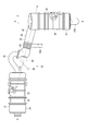
- the top view which shows the exhaust-gas aftertreatment apparatus mounted in a dump truck.
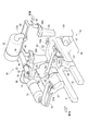
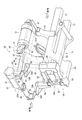
- the perspective view which looked at the frame of a dump truck and the exhaust-gas aftertreatment device from diagonally forward and upward.
- 1 and 2 are a side view and a plan view showing the main part of the dump truck 1 of the present embodiment. 1 and 2, the dump truck 1 is configured as an articulated dump truck in which a front frame 1A and a rear frame 1B are swingably connected via a connecting portion 55A (FIGS. 4 and 5).
- a front frame 1A as a vehicle body frame of the dump truck 1 is provided with a front wheel 2 via a front axle and a front suspension, and a cab 3 is placed via a cab mount for vibration absorption / damping.
- an engine chamber 4 is provided on the front side of the cab 3 so that the upper side is covered with an openable / closable bonnet 4A and the left and right sides are covered with a partition wall 4B.
- a diesel engine (hereinafter abbreviated as engine) 5 is arranged in the engine room 4, a radiator cooling fan 6 is disposed in front of the engine 5, a radiator 7 is disposed in front of the cooling fan 6, and an air conditioner condenser 8 is disposed in front of the radiator 7.
- An exhaust turbocharger 9 is attached to the engine 5.
- a ventilation chamber 14 covered with a side cover 14A is provided on the right side of the engine chamber 4.
- the ventilation chamber 14 and the engine chamber 4 are partitioned by a right partition 4B.
- An air cleaner 15 is partially exposed in the ventilation chamber 14, an after cooler 16 is disposed behind the air cleaner 15, and an after cooler cooling fan 17 is disposed behind the after cooler 16. .
- a right fender 18 is provided behind the ventilation chamber 14, that is, on the right side of the cab 3.
- a DPF (diesel particulate filter) installation chamber 19 is provided at the upper part of the right fender 18 and is surrounded on the upper and side sides.
- the front side of the DPF installation chamber 19 is open, and the ventilation chamber 14 and the DPF installation chamber 19 communicate with each other in the front-rear direction.
- the upper surface of the DPF installation chamber 19 is an access passage 21.
- the access passage 21 is higher than the left access passage 12 because the DPF installation chamber 19 is provided below.
- the access passage 21 can rise from the ground through the ladder 22.
- the intake air flowing into the air cleaner 15 is supplied to the compressor of the exhaust turbo supercharger 9 through the intake pipe 23 and is supercharged by the compressor.
- the supercharged intake air is sent to the aftercooler 16 through the intake pipe 24.
- the intake air heat-exchanged (cooled) by the aftercooler 16 is supplied to the engine 5 through the intake pipe 25 and an intake manifold (not shown).
- Exhaust gas from the engine 5 is sent to the turbine of the exhaust turbocharger 9 through an exhaust manifold and an exhaust pipe 26 (not shown), and after driving the turbine, is sent to an exhaust gas aftertreatment device 30 (to be described later) through the exhaust pipe 27.
- the exhaust gas that has passed through the exhaust gas aftertreatment device 30 is sent to the exhaust circuit for body heating provided in the rear body 29 through the exhaust pipe 28 (FIG. 1).
- the exhaust gas that has passed through the exhaust circuit is discharged from an exhaust port provided in the body 29. When the body 29 is in an inclined position and is away from the end of the exhaust pipe 28, the exhaust gas is directly discharged from the end of the exhaust pipe 28.
- the cooling fan 17 for the aftercooler by driving the cooling fan 17 for the aftercooler, the outside air is drawn into the ventilation chamber 14 from the plurality of intake ports 14B in the front part of the side cover 14A as cooling air.
- the surface of the air cleaner 15 is cooled by a part of the cooling air.
- the cooling air cools the aftercooler 16 and flows into the DPF installation chamber 19.
- the inflowing cooling air cools a DPF device 31 (described later) as a filter device of the exhaust gas aftertreatment device 30 and is discharged from the rear portion of the DPF installation chamber 19.
- the body 29 is supported by the rear frame 1B so as to be able to move up and down, and is driven by a hoist cylinder including a pair of hydraulic actuators (not shown).
- the exhaust-gas aftertreatment apparatus 30 in this embodiment is demonstrated.
- 3 to 5 are a plan view showing the exhaust gas aftertreatment device 30, a perspective view seen from the front obliquely upper side, and a perspective view seen from the obliquely lower rear side.
- the exhaust gas aftertreatment device 30 includes a DPF device 31 installed in the DPF installation chamber 19 (FIGS. 1 and 2) and connected to the rear end of the exhaust pipe 27, and the DPF device 31.
- An SCR (Selective Reduction Catalyst) device 32 as a catalytic device installed on the downstream side and between the cab 3 and the body 29, and a communication for communicating the downstream end of the DPF device 31 and the upstream end of the SCR device 32 A tube 33.
- the DPF device 31, the SCR device 32, and the communication pipe 33 are installed at substantially the same height level, although there is a slight vertical difference.
- the DPF device 31 includes a cylindrical case 34.
- the axis AA of the DPF device 31 is parallel to the longitudinal direction of the vehicle.
- the exhaust gas flows in the DPF device 31 from the front side to the rear side along the front-rear direction of the vehicle.
- Inside the case 34 are housed a DPF 35 that collects PM in the exhaust gas and an oxidation catalyst 36 that activates the dosing fuel.
- the oxidation catalyst 36 is disposed on the upstream side of the DPF 35.
- the dosing fuel is the same as the fuel of the engine 5, for example, and is supplied into the exhaust gas in order to cause the PM collected by the DPF 35 to self-combust.
- the dosing fuel may be supplied as post injection into the cylinder of the engine 5 or may be injected into the exhaust pipe 27.
- the dosing fuel supplied into the exhaust gas is activated by the oxidation catalyst 36 and raises the temperature of the exhaust gas to the combustion temperature of PM.
- the PM collected by the DPF 35 is self-combusted by the high heat of the exhaust gas, and the DPF 35 is regenerated to a state where the PM is not clogged. Since the specific structures and the like of the DPF 35 and the oxidation catalyst 36 are known, description thereof is omitted here.
- the SCR device 32 also includes a cylindrical case 37.
- the axis BB of the SCR device 32 is orthogonal to the longitudinal direction of the vehicle, that is, the axis AA of the DPF device 31 in plan view.
- An outlet pipe 37A provided in the case 37 is bent vertically downward and is connected to the exhaust pipe 28 (FIG. 1) described above.
- a selective reduction catalyst 38 for reducing and purifying nitrogen oxides in the exhaust gas is ammonia obtained from an aqueous urea solution. Since the structure and the like of the selective reduction catalyst 38 are already known, description thereof is omitted here.
- An oxidation catalyst for reducing ammonia for oxidizing excess ammonia may be provided on the downstream side of the selective reduction catalyst 38.
- the communication pipe 33 includes an upstream curved pipe 41 and a downstream mixing pipe 42.
- the curved pipe 41 has a bent shape with a large diameter so as to swell to the side of the vehicle, and allows the DPF device 31 and the mixing pipe 42 to communicate with each other without reducing the flow path area.
- a bellows pipe is disposed as necessary to prevent the vibration on the DPF device 31 side from being transmitted to the mixing pipe 42 side.
- the mixing pipe 42 has an axis CC inclined at an angle ⁇ 1 in the plan view with respect to the longitudinal direction of the vehicle, that is, the axis AA of the DPF device 31. That is, the downstream side of the mixing pipe 42 is directed to the inner side of the vehicle.
- the exhaust gas flows in from a direction orthogonal to the axis CC in a plan view, and the flow of the exhaust gas flowing in is changed to a direction along the axis CC.
- a first elbow portion 43 that is positioned downstream of the first elbow portion 43, a straight pipe portion 44 having a predetermined length along the axis CC, and a downstream side of the straight pipe portion 44, the axis C And a second elbow portion 45 bent vertically upward with respect to ⁇ C.
- the axis AA and the axis BB described above including the axis CC are all horizontal axes.
- an injector 46 for injecting an aqueous urea solution into the mixing pipe 42 is attached on the extension of the axis CC.
- the urea aqueous solution is pumped up by the supply module 48 from the urea aqueous solution tank 47 disposed on the lower front side of the right fender 18 (FIG. 1), and is supplied to the injector 46 through the supply tube 49.
- the urea aqueous solution injected from the injector 46 is thermally decomposed by being mixed with the exhaust gas in the straight pipe portion 44 to obtain ammonia.
- This ammonia serves as a reducing agent and is supplied to the downstream selective reduction catalyst 38 through the second elbow portion 45 to purify nitrogen oxides in the exhaust gas.
- the front frame 1 ⁇ / b> A has a pair of left and right side members 51, 51 along the longitudinal direction of the vehicle body.
- a cross member 52 is installed at the rear end of the side member 51.
- a similar cross member 53 is provided below the cross member 52. Both ends of the cross members 52 and 53 are connected vertically by a vertical support member 54.
- the articulate support 55 is provided with a connecting portion 55A to which the rear frame 1B (FIG. 1) is connected by an unillustrated articulate pin.
- the articulate support 55 and each side member 51 are connected by a reinforcing side member 56.
- a front pillar 57 is erected in the middle of each side member 51 in the longitudinal direction, and a rear pillar 58 is erected at the rear end of each support member 54.
- Flat mounting surfaces 57A and 58A are provided at the upper ends of the front pillar 57 and the rear pillar 58, respectively.
- the lower side of the cab 3 is placed on the placement surfaces 57A and 58A via a cab mount.
- a rotation mechanism is provided between the mounting surface 58 ⁇ / b> A of the rear pillar 58 and the cab 3. By this rotation mechanism, the cab 3 can be tilted up to the rear side by a predetermined angle (see a two-dot chain line in FIG. 1).
- a support frame 61 extending horizontally toward the right is provided on the upper part of the right front pillar 57.
- a bracket 62 shaped like the right fender 18 is provided on the side surface of the right vertical support member 54.
- the bracket 62 is used, for example, as an attachment location for an accumulator or the like incorporated in a hydraulic circuit.
- a rectangular attachment plate 63 is installed on the upper portion of the bracket 62 and the support frame 61.
- the upper part of the bracket 62 and the upper part of the right rear pillar 58 are connected via an L-shaped connecting frame 64.
- the DPF device 31 is mounted on the mounting plate 63 by appropriate mounting means such as a V clamp.
- the mounting surfaces 58A of the left and right rear pillars 58 are provided with mounting surface portions 58B that are continuously extended on the rear side.
- a support frame 65 extending horizontally rearward is attached to these attachment surface portions 58B.
- a rectangular mounting plate 66 is installed between the support frames 65.
- the SCR device 32 is mounted on the mounting plate 66 by appropriate mounting means such as a V clamp.
- the mounting plate 66 is also provided with a building-shaped cover 67 that covers the entire SCR device 32.
- the communication tube 33 is attached to the aforementioned L-shaped connection frame 64 via a bracket 33A (FIG. 3) provided in the middle. It is done.
- the mixing pipe 42 of the communication pipe 33 is inclined by the angle ⁇ 1 in plan view with respect to the longitudinal direction of the vehicle body (the same direction as the axis AA of the DPF device 31).
- the piping is made using a narrow space between the cab 3 and the ladder 22 (FIG. 2).
- the downstream side from the vicinity of the rear end of the curved pipe 41 protrudes from the DPF installation chamber 19.
- the side and bottom sides of the bent pipe 41 and the first elbow portion 43 of the mixing pipe 42 are covered with a cover 68.
- the upper part is covered with plate-like steps 21A and 21B provided as an extension of the access passage 21 (FIG. 2).
- the mixing pipe 42 is covered with a cover 69 having a U-shaped cross section that opens toward the inside of the vehicle body.
- the covers 67, 68, and 69 This prevents a serviceman or an operator who moves up and down the ladder 22 provided adjacent to the SCR device 32 and the communication pipe 33 from easily touching the SCR device 32 and the communication pipe 33 that become high temperature. The heat from them is shut off.
- the ladder 22 of this embodiment has a plurality of steps 22A.
- Each step 22A extends toward the rear outer side of the vehicle body by an angle ⁇ 2 (FIG. 2) in a plan view with respect to the longitudinal direction of the vehicle body (the same direction as the axis AA of the DPF device 31).
- the service person and the operator who move up and down the ladder 22 are further away from the SCR device 32 and the mixing pipe 42 of the communication pipe 33 and are difficult to touch them.
- the mixing pipe 42 that passes through the narrow space between the cab 3 and the ladder 22 is inclined at an angle ⁇ 1 (FIG. 3) on the downstream side thereof with respect to the axis AA opposite to the angle ⁇ 2 in a plan view. Therefore, it is further separated from the ladder 22 on the rear side, and this point is further difficult to touch.
- the SCR device 32 is installed between the cab 3 and the body 29 in the longitudinal direction of the vehicle body. Yes.
- the SCR device 32 is also installed on the right side of the center in the left-right direction of the vehicle body. Due to the connection with the exhaust pipe 28, the downstream end of the outlet pipe 37A provided in the SCR device 32 is located at the approximate center in the left-right direction of the vehicle body.
- the SCR device 32 is installed at a position where it does not interfere with the hook-shaped guard 3 ⁇ / b> A provided behind the cab 3. In this case, the vertical position is a position where the cab 3 does not interfere with the cab 3 or the guard 3A even when the cab 3 is tilted rearward (see the two-dot chain line in FIG. 1).
- the guard 3A is provided to protect the valve device for the hydraulic circuit disposed below the SCR device 32 from falling rocks or the like during loading work. However, since the SCR device 32 is also protected by the guard 3A, damage to the SCR device 32 and damage to the cover 67 that covers the SCR device 32 can be suppressed. In addition, since the SCR device 32 is located at a high position behind the cab 3, there is no fear of hitting pebbles or the like jumping while the dump truck 1 is traveling, and even if the vehicle body sinks in a soft ground, it can be buried. Absent. Also in this respect, damage to the SCR device 32 can be suppressed.
- the present invention is not limited to the above-described embodiment, and modifications, improvements, and the like within the scope that can achieve the object of the present invention are included in the present invention.
- the cab 3 is rotatably supported on the front frame 1A and is provided so as to be tilted up rearward.
- the cab tilt-up direction is arbitrary, and the front or side is In this case, it may be tilted up, or may not be tilted up.
- the SCR device 32 of the exhaust gas aftertreatment device 30 is attached to the front frame 1A via the support frame 65.
- the present invention is not limited to this. Included in the invention. In particular, when the cab does not tilt up with respect to the front frame, the position of the SCR device does not change significantly.
- the cab is mounted on the front frame through a cab mount for vibration absorption and vibration damping, and the vibration system is different from the front frame.
- a bellows pipe for absorbing different vibrations between the communication pipe and the SCR device. Etc., and the structure becomes complicated. Therefore, in such a case, it is desirable to attach the SCR device to the front frame as in the above embodiment.
- the present invention can be used not only for articulated dump trucks but also for rigid dump trucks.
Landscapes
- Engineering & Computer Science (AREA)
- Chemical & Material Sciences (AREA)
- Mechanical Engineering (AREA)
- Combustion & Propulsion (AREA)
- General Engineering & Computer Science (AREA)
- Transportation (AREA)
- Chemical Kinetics & Catalysis (AREA)
- Health & Medical Sciences (AREA)
- Toxicology (AREA)
- Exhaust Gas After Treatment (AREA)
- Cooling, Air Intake And Gas Exhaust, And Fuel Tank Arrangements In Propulsion Units (AREA)
- Processes For Solid Components From Exhaust (AREA)
Abstract
Description
しかし、第3発明によれば、ラダーのステップを車体の後方外側に向けて延設させているので、連通管からより離間した位置でラダーを利用でき、連通管に気を取られることなくラダーを迅速に昇降できる。
図1、図2は、本実施形態のダンプトラック1の要部を示す側面図および平面図である。図1、図2において、ダンプトラック1は、フロントフレーム1Aおよびリアフレーム1Bが連結部55A(図4、図5)を介して揺動自在に連結されたアーティキュレートダンプトラックとして構成されている。
ダンプトラック1の車体フレームとしてのフロントフレーム1Aには、フロントアクスルおよびフロントサスペンションを介して前輪2が設けられ、振動吸収・減衰用のキャブマウントを介してキャブ3が載置されている。フロントフレーム1Aにおいて、キャブ3の前方側には、上方が開閉自在なボンネット4Aで覆われ、左右の側方が隔壁4Bで覆われたエンジン室4が設けられている。
エアクリーナ15に流入した吸気は、吸気管23を通って排気ターボ過給機9のコンプレッサに供給され、コンプレッサにて過給される。過給された吸気は、吸気管24を通してアフタークーラ16に送られる。アフタークーラ16にて熱交換(冷却)された吸気は、吸気管25および図示しない吸気マニホールドを通してエンジン5に供給される。
以下には、本実施形態での排気ガス後処理装置30について説明する。
図3~図5は、排気ガス後処理装置30を示す平面図、前方斜め上方から見た斜視図、および後方斜め下方から見た斜視図である。図3~図5において、排気ガス後処理装置30は、DPF設置室19(図1、図2)内に設置されて排気管27の後端に接続されるDPF装置31と、DPF装置31の下流側に位置してキャブ3とボディ29との間に設置された触媒装置としてのSCR(選択還元触媒)装置32と、これらDPF装置31の下流端およびSCR装置32の上流端を連通させる連通管33とを備える。これらDPF装置31、SCR装置32、および連通管33は、多少の上下差はあるが、略同一の高さレベルで設置される。
次に、排気ガス後処理装置30の搭載構造について説明する。
図4、図5に示すように、フロントフレーム1Aは、車体の前後方向に沿った左右一対のサイドメンバー51,51を有している。サイドメンバー51の後端には、クロスメンバー52が架設されている。クロスメンバー52の下方には、同様なクロスメンバー53が設けられている。クロスメンバー52,53の両端は、鉛直なサポートメンバー54にて上下に連結されている。
例えば、前記実施形態では、キャブ3がフロントフレーム1Aに回動自在に支承され、後方にチルトアップ可能に設けられていたが、本発明では、キャブのチルトアップ方向は任意であり、前方または側方にチルトアップする場合であってもよく、また、チルトアップしない場合であってもよい。
Claims (5)
- エンジンが収容されるエンジン室の後方にキャブが配置されるとともに、キャブの後方にボディが配置され、かつ前記エンジンからの排気ガスを浄化する排気ガス後処理装置が搭載されたダンプトラックにおいて、
前記排気ガス後処理装置は、
前記排気ガス中の粒子状物質を捕集するフィルタ装置と、
前記排気ガス中の窒素酸化物を浄化する触媒装置と、
前記フィルタ装置および前記触媒装置を連通させる連通管とを備え、
前記フィルタ装置は、前記キャブの側方に設けられたフェンダの上部に設置され、
前記触媒装置は、前記キャブと前記ボディとの間に設置される
ことを特徴とするダンプトラック。 - 請求項1に記載のダンプトラックにおいて、
前記キャブは、車体フレームに対してチルトアップ可能に載置され、
前記触媒装置は、前記キャブと前記ボディとの間に設置されて前記車体フレームに取り付けられる
ことを特徴とするダンプトラック。 - 請求項1または請求項2に記載のダンプトラックにおいて、
前記フェンダの後部には、車体の後方外側に向けて延設された複数段のステップを有するラダーが設けられ、
前記連通管は、前記ラダーと前記キャブとの間を通して配置される
ことを特徴とするダンプトラック。 - 請求項1ないし請求項3のいずれかに記載のダンプトラックにおいて、
前記フェンダの後部には、複数段のステップを有するラダーが設けられ、
前記フィルタ装置は、排気ガスが車体の前後方向と平行に流れるように設置され、
前記連通管は、下流側が前記車体の前後方向に対し平面視にて内方側に傾いた状態で前記ラダーと前記キャブとの間を通して配置される
ことを特徴とするダンプトラック。 - 請求項3または請求項4に記載のダンプトラックにおいて、
前記触媒装置および前記連通管は、少なくとも前記ラダー側に臨む部分がカバーで覆われている
ことを特徴とするダンプトラック。
Priority Applications (4)
| Application Number | Priority Date | Filing Date | Title |
|---|---|---|---|
| JP2013547742A JP5438249B1 (ja) | 2012-10-30 | 2013-06-20 | ダンプトラック |
| EP13815665.8A EP2754580B1 (en) | 2012-10-30 | 2013-06-20 | Dumptruck |
| CN201380002216.5A CN103917395B (zh) | 2012-10-30 | 2013-06-20 | 自卸车辆 |
| US14/233,446 US8820468B2 (en) | 2012-10-30 | 2013-06-20 | Dump truck |
Applications Claiming Priority (2)
| Application Number | Priority Date | Filing Date | Title |
|---|---|---|---|
| JP2012-239444 | 2012-10-30 | ||
| JP2012239444 | 2012-10-30 |
Publications (1)
| Publication Number | Publication Date |
|---|---|
| WO2014069038A1 true WO2014069038A1 (ja) | 2014-05-08 |
Family
ID=50626959
Family Applications (2)
| Application Number | Title | Priority Date | Filing Date |
|---|---|---|---|
| PCT/JP2013/063205 Ceased WO2014069026A1 (ja) | 2012-10-30 | 2013-05-10 | 排気ガス後処理装置を搭載した建設車両 |
| PCT/JP2013/066932 Ceased WO2014069038A1 (ja) | 2012-10-30 | 2013-06-20 | ダンプトラック |
Family Applications Before (1)
| Application Number | Title | Priority Date | Filing Date |
|---|---|---|---|
| PCT/JP2013/063205 Ceased WO2014069026A1 (ja) | 2012-10-30 | 2013-05-10 | 排気ガス後処理装置を搭載した建設車両 |
Country Status (5)
| Country | Link |
|---|---|
| US (2) | US8985262B2 (ja) |
| EP (2) | EP2752327B1 (ja) |
| JP (2) | JP5439634B1 (ja) |
| CN (2) | CN104024016B (ja) |
| WO (2) | WO2014069026A1 (ja) |
Cited By (3)
| Publication number | Priority date | Publication date | Assignee | Title |
|---|---|---|---|---|
| JP2019019782A (ja) * | 2017-07-19 | 2019-02-07 | 三菱ロジスネクスト株式会社 | 排気ガス浄化装置付き作業車両 |
| GB2585099A (en) * | 2019-06-26 | 2020-12-30 | Bamford Excavators Ltd | A working machine |
| US11325569B2 (en) | 2019-08-29 | 2022-05-10 | Pat Beaver | Dump-truck fluid assistance system and method |
Families Citing this family (35)
| Publication number | Priority date | Publication date | Assignee | Title |
|---|---|---|---|---|
| KR20120052512A (ko) * | 2010-11-16 | 2012-05-24 | 대동공업주식회사 | 농업용 작업차량의 배기가스 후처리장치의 취부구조 |
| KR101451182B1 (ko) * | 2012-08-23 | 2014-10-15 | 대동공업주식회사 | 농업용 작업차량의 배기가스 후처리장치 취부구조 |
| JP5442830B1 (ja) * | 2012-10-16 | 2014-03-12 | 株式会社小松製作所 | 油圧ショベル |
| JP5449517B1 (ja) * | 2012-12-20 | 2014-03-19 | 株式会社小松製作所 | 作業車両 |
| DE112013000122B4 (de) * | 2013-02-15 | 2017-06-14 | Komatsu Ltd. | Hydraulikbagger |
| JP6178149B2 (ja) * | 2013-07-24 | 2017-08-09 | ヤンマー株式会社 | トラクター |
| US9441527B2 (en) * | 2013-08-09 | 2016-09-13 | Komatsu Ltd. | Supporting mechanism, exhaust treatment unit, and wheel loader |
| US9157214B2 (en) * | 2013-09-30 | 2015-10-13 | Komatsu Ltd. | Bulldozer |
| JP5867485B2 (ja) * | 2013-11-20 | 2016-02-24 | コベルコ建機株式会社 | 建設機械 |
| JP5989017B2 (ja) * | 2014-01-30 | 2016-09-07 | 日立建機株式会社 | 建設機械 |
| JP6297905B2 (ja) * | 2014-04-22 | 2018-03-20 | 日立建機株式会社 | 建設機械 |
| EP2985166B1 (en) | 2014-08-14 | 2017-08-02 | CNH Industrial Italia S.p.A. | Exhaust system for an off-road vehicle |
| CN104428470B (zh) | 2014-08-25 | 2018-08-24 | 株式会社小松制作所 | 推土机 |
| KR101917966B1 (ko) * | 2014-10-06 | 2018-11-12 | 얀마 가부시키가이샤 | 엔진 장치 |
| CN104386145A (zh) * | 2014-11-20 | 2015-03-04 | 东风柳州汽车有限公司 | 排式举升操纵器 |
| CN107002532B (zh) * | 2014-11-21 | 2019-07-09 | 株式会社Kcm | 产业用车辆 |
| JP5894342B2 (ja) * | 2014-12-01 | 2016-03-30 | 株式会社小松製作所 | ダンプトラック |
| CA2898553C (en) * | 2014-12-01 | 2016-08-09 | Hirokazu Ashikawa | Dump truck |
| US20150102179A1 (en) * | 2014-12-22 | 2015-04-16 | Caterpillar Inc. | Bracket to mount aftercooler to engine |
| US9925862B2 (en) * | 2015-01-26 | 2018-03-27 | Bullseye Power LLC | Turbine compressor wheel with axially extended blades |
| EP3418521B1 (en) | 2016-02-19 | 2021-04-21 | Yanmar Power Technology Co., Ltd. | Engine device |
| CA2934750C (en) * | 2016-03-31 | 2017-07-04 | Takamu Kanayama | Dump truck |
| US10800225B2 (en) * | 2016-08-03 | 2020-10-13 | Komatsu Ltd. | Working vehicle |
| WO2019068313A1 (en) * | 2017-10-03 | 2019-04-11 | Volvo Lastvagnar Ab | PROCESS FOR COOLING AT LEAST ONE COMPONENT, SUCH AS A SENSOR, ARRANGED INSIDE A COMPARTMENT OF A VEHICLE EXHAUST GAS POST-TREATMENT SYSTEM |
| JP6881334B2 (ja) * | 2018-01-29 | 2021-06-02 | 株式会社豊田自動織機 | 排気ガス浄化装置 |
| WO2018151335A1 (ja) | 2018-03-12 | 2018-08-23 | 株式会社小松製作所 | ダンプトラック |
| CN108361099B (zh) * | 2018-05-16 | 2020-08-21 | 潍柴动力股份有限公司 | 一种汽车的电控风扇控制方法、控制装置和汽车 |
| JP7273619B2 (ja) * | 2018-06-01 | 2023-05-15 | マニタウォック クレイン カンパニーズ, エルエルシー | クレーン下部走行体上のエンジン排気後処理システムのための取り付け配設 |
| US11293148B2 (en) * | 2019-03-04 | 2022-04-05 | Caterpillar Paving Products Inc. | Step assembly and walkway for a screed |
| JP7137500B2 (ja) * | 2019-03-18 | 2022-09-14 | 株式会社クボタ | 作業車 |
| US11660955B2 (en) * | 2019-03-18 | 2023-05-30 | Kubota Corporation | Fuel tank of work vehicle and work vehicle |
| JP7424736B2 (ja) * | 2020-03-06 | 2024-01-30 | キャタピラー エス エー アール エル | 機体および作業機械 |
| JP7503975B2 (ja) * | 2020-09-04 | 2024-06-21 | 株式会社小松製作所 | 作業機械 |
| JP7557350B2 (ja) * | 2020-11-19 | 2024-09-27 | ヤンマーホールディングス株式会社 | ディーゼルエンジン |
| JP2025140528A (ja) * | 2024-03-14 | 2025-09-29 | 株式会社小松製作所 | 作業車両 |
Citations (4)
| Publication number | Priority date | Publication date | Assignee | Title |
|---|---|---|---|---|
| JP2002371833A (ja) * | 2001-06-15 | 2002-12-26 | Hino Motors Ltd | 排気浄化装置 |
| JP2010096014A (ja) | 2008-10-14 | 2010-04-30 | Komatsu Ltd | 作業機械の冷却装置 |
| JP2011033011A (ja) * | 2009-08-06 | 2011-02-17 | Mitsubishi Fuso Truck & Bus Corp | 内燃機関の排気浄化装置 |
| JP2011043078A (ja) * | 2009-08-19 | 2011-03-03 | Mitsubishi Fuso Truck & Bus Corp | 内燃機関の排気浄化装置 |
Family Cites Families (45)
| Publication number | Priority date | Publication date | Assignee | Title |
|---|---|---|---|---|
| US2769501A (en) * | 1952-10-09 | 1956-11-06 | Int Harvester Co | Bumper, radiator, and grille assembly for sectional vehicle cab |
| US3731973A (en) * | 1971-09-30 | 1973-05-08 | Gen Motors Corp | Valve assembly for exhaust system |
| US4074786A (en) * | 1976-08-10 | 1978-02-21 | Steiger Tractor Inc. | Self locking compartment for tractor |
| DE4423003C2 (de) * | 1993-07-06 | 1999-01-21 | Ford Werke Ag | Verfahren und Vorrichtung zum Reduzieren von NO¶x¶ in den Abgasen von Kraftfahrzeugverbrennungsmotoren |
| DE19729003C2 (de) | 1997-07-07 | 1999-05-27 | Siemens Ag | Tank für ein Fahrzeug mit reduktionsmittelbetriebener Abgas-Reinigungsanlage |
| US6223526B1 (en) * | 1998-06-17 | 2001-05-01 | Siemens Aktiengesellschaft | Dual compartment fuel storage tank |
| US20030084658A1 (en) * | 2000-06-20 | 2003-05-08 | Brown Kevin F | Process for reducing pollutants from the exhaust of a diesel engine using a water diesel fuel in combination with exhaust after-treatments |
| US20080256936A1 (en) * | 2007-04-17 | 2008-10-23 | Geo2 Technologies, Inc. | Selective Catalytic Reduction Filter and Method of Using Same |
| US6874589B1 (en) * | 2002-12-16 | 2005-04-05 | Crane Carrier Company | Deck mounted air cleaner assembly for vehicle |
| JP4361001B2 (ja) * | 2004-10-28 | 2009-11-11 | 日産ディーゼル工業株式会社 | リヤエンジンバスの排気浄化装置 |
| US8015802B2 (en) * | 2004-11-25 | 2011-09-13 | Komatsu Ltd. | Exhaust gas purification device for internal combustion engine |
| US7624572B2 (en) * | 2004-12-29 | 2009-12-01 | Caterpillar Inc. | Exhaust treatment device monitoring system |
| US7762060B2 (en) * | 2006-04-28 | 2010-07-27 | Caterpillar Inc. | Exhaust treatment system |
| US20080078166A1 (en) * | 2006-09-29 | 2008-04-03 | Charles Rose | Hybrid engine exhaust gas temperature control system |
| JP4656039B2 (ja) * | 2006-10-19 | 2011-03-23 | 株式会社デンソー | エンジンの排気浄化装置 |
| JP5273933B2 (ja) | 2007-03-28 | 2013-08-28 | 株式会社小松製作所 | 建設車両 |
| JP4900163B2 (ja) * | 2007-09-26 | 2012-03-21 | コベルコ建機株式会社 | 建設機械 |
| US8056671B2 (en) * | 2007-10-12 | 2011-11-15 | Mazda Motor Corporation | Exhaust-gas purification device disposition structure of vehicle |
| JP5012406B2 (ja) * | 2007-10-22 | 2012-08-29 | コベルコ建機株式会社 | 建設機械 |
| JP2009115050A (ja) * | 2007-11-09 | 2009-05-28 | Mitsubishi Fuso Truck & Bus Corp | ハイブリッド電気自動車の排気浄化装置 |
| WO2009070734A1 (en) * | 2007-11-26 | 2009-06-04 | Michigan Technological University | Nox control systems and methods for controlling nox emissions |
| JP5101324B2 (ja) * | 2008-02-07 | 2012-12-19 | 日立建機株式会社 | 建設機械のNOx低減装置の配設構造 |
| JP5054613B2 (ja) * | 2008-05-16 | 2012-10-24 | 三菱ふそうトラック・バス株式会社 | エンジンの排気ガス浄化装置 |
| CN102036846B (zh) * | 2008-05-22 | 2013-11-06 | 日立建机株式会社 | 工程机械 |
| EP2302180B1 (en) * | 2008-07-10 | 2014-04-30 | Hitachi Construction Machinery Co., Ltd | Construction machine |
| US8191668B2 (en) * | 2008-08-07 | 2012-06-05 | Caterpillar Inc. | Mounting assembly for emissions control system |
| JP5107822B2 (ja) * | 2008-08-11 | 2012-12-26 | 日立建機株式会社 | 排気ガス浄化装置 |
| EP2341227B1 (en) * | 2008-10-28 | 2018-08-29 | Yanmar Co., Ltd. | Engine device for mounting on working vehicle |
| JP2010106716A (ja) * | 2008-10-29 | 2010-05-13 | Komatsu Ltd | Pmフィルタ装置の保温・冷却制御装置 |
| US20100326059A1 (en) * | 2009-06-26 | 2010-12-30 | Gm Global Technology Operations, Inc. | Selective catalytic reduction exhaust aftertreatment system and engine incorporating the same |
| JP2011047390A (ja) * | 2009-08-29 | 2011-03-10 | Iseki & Co Ltd | 作業車両 |
| CN101659207A (zh) * | 2009-09-14 | 2010-03-03 | 喻谦鹏 | 汽车排气净化装置 |
| JP5402451B2 (ja) * | 2009-09-17 | 2014-01-29 | コベルコ建機株式会社 | 建設機械 |
| US8555625B2 (en) * | 2009-11-13 | 2013-10-15 | Pierce Manufacturing Company | Exhaust system for firefighting vehicle |
| FR2952674B1 (fr) * | 2009-11-17 | 2012-11-16 | Peugeot Citroen Automobiles Sa | Procede de controle d'un systeme de traitement des gaz d'echappement d'un moteur a combustion interne |
| JP5372727B2 (ja) | 2009-12-24 | 2013-12-18 | いすゞ自動車株式会社 | 還元剤タンクの固定構造 |
| KR20120088764A (ko) * | 2010-05-31 | 2012-08-08 | 가부시키가이샤 고마쓰 세이사쿠쇼 | 작업 차량 |
| JP5562777B2 (ja) * | 2010-09-16 | 2014-07-30 | 日立建機株式会社 | 建設機械 |
| JP5356341B2 (ja) * | 2010-09-16 | 2013-12-04 | 日立建機株式会社 | 建設機械 |
| US8556014B2 (en) * | 2010-11-03 | 2013-10-15 | Caterpillar Inc. | Diesel particulate filter packaging and method of directing airflow in a skid steer machine |
| JP2012171596A (ja) * | 2011-02-24 | 2012-09-10 | Hitachi Constr Mach Co Ltd | 建設機械 |
| US20130000281A1 (en) | 2011-06-30 | 2013-01-03 | Caterpillar Inc. | Def pump mounted to tank |
| US9186654B2 (en) * | 2011-11-03 | 2015-11-17 | GM Global Technology Operations LLC | Low cost lean NOx reduction catalyst system |
| JP5865040B2 (ja) * | 2011-11-30 | 2016-02-17 | 株式会社クボタ | 作業車 |
| US20130327017A1 (en) * | 2012-06-07 | 2013-12-12 | Caterpillar, Inc. | Exhaust System, Operating Method And Control Strategy In Internal Combustion Engine |
-
2013
- 2013-05-10 WO PCT/JP2013/063205 patent/WO2014069026A1/ja not_active Ceased
- 2013-05-10 CN CN201380001066.6A patent/CN104024016B/zh active Active
- 2013-05-10 JP JP2013543453A patent/JP5439634B1/ja not_active Expired - Fee Related
- 2013-05-10 EP EP13780047.0A patent/EP2752327B1/en not_active Not-in-force
- 2013-05-10 US US14/114,860 patent/US8985262B2/en active Active
- 2013-06-20 JP JP2013547742A patent/JP5438249B1/ja not_active Expired - Fee Related
- 2013-06-20 WO PCT/JP2013/066932 patent/WO2014069038A1/ja not_active Ceased
- 2013-06-20 EP EP13815665.8A patent/EP2754580B1/en active Active
- 2013-06-20 CN CN201380002216.5A patent/CN103917395B/zh active Active
- 2013-06-20 US US14/233,446 patent/US8820468B2/en active Active
Patent Citations (4)
| Publication number | Priority date | Publication date | Assignee | Title |
|---|---|---|---|---|
| JP2002371833A (ja) * | 2001-06-15 | 2002-12-26 | Hino Motors Ltd | 排気浄化装置 |
| JP2010096014A (ja) | 2008-10-14 | 2010-04-30 | Komatsu Ltd | 作業機械の冷却装置 |
| JP2011033011A (ja) * | 2009-08-06 | 2011-02-17 | Mitsubishi Fuso Truck & Bus Corp | 内燃機関の排気浄化装置 |
| JP2011043078A (ja) * | 2009-08-19 | 2011-03-03 | Mitsubishi Fuso Truck & Bus Corp | 内燃機関の排気浄化装置 |
Non-Patent Citations (1)
| Title |
|---|
| See also references of EP2754580A4 |
Cited By (4)
| Publication number | Priority date | Publication date | Assignee | Title |
|---|---|---|---|---|
| JP2019019782A (ja) * | 2017-07-19 | 2019-02-07 | 三菱ロジスネクスト株式会社 | 排気ガス浄化装置付き作業車両 |
| GB2585099A (en) * | 2019-06-26 | 2020-12-30 | Bamford Excavators Ltd | A working machine |
| GB2585099B (en) * | 2019-06-26 | 2024-01-03 | Bamford Excavators Ltd | A working machine |
| US11325569B2 (en) | 2019-08-29 | 2022-05-10 | Pat Beaver | Dump-truck fluid assistance system and method |
Also Published As
| Publication number | Publication date |
|---|---|
| EP2754580A4 (en) | 2015-06-24 |
| JPWO2014069038A1 (ja) | 2016-09-08 |
| EP2752327B1 (en) | 2016-09-28 |
| EP2754580A1 (en) | 2014-07-16 |
| CN103917395A (zh) | 2014-07-09 |
| US20140124284A1 (en) | 2014-05-08 |
| JPWO2014069026A1 (ja) | 2016-09-08 |
| JP5438249B1 (ja) | 2014-03-12 |
| CN104024016A (zh) | 2014-09-03 |
| WO2014069026A1 (ja) | 2014-05-08 |
| EP2752327A1 (en) | 2014-07-09 |
| CN103917395B (zh) | 2015-07-29 |
| CN104024016B (zh) | 2016-08-31 |
| EP2754580B1 (en) | 2017-02-15 |
| US8985262B2 (en) | 2015-03-24 |
| US8820468B2 (en) | 2014-09-02 |
| JP5439634B1 (ja) | 2014-03-12 |
| EP2752327A4 (en) | 2015-09-09 |
| US20140182963A1 (en) | 2014-07-03 |
Similar Documents
| Publication | Publication Date | Title |
|---|---|---|
| JP5438249B1 (ja) | ダンプトラック | |
| CN105051342B (zh) | 发动机装置 | |
| CN105074153B (zh) | 工程机械 | |
| US9394817B2 (en) | Cooling structure for urea aqueous solution conduit | |
| JP6385323B2 (ja) | 建設機械 | |
| KR101776120B1 (ko) | 건설기계 | |
| CN102666174A (zh) | 作业车辆 | |
| CN104185708B (zh) | 推土机 | |
| CN106574456A (zh) | 作业机械 | |
| CN105102096B (zh) | 作业车辆 | |
| JP5894342B2 (ja) | ダンプトラック | |
| JP5864036B1 (ja) | ダンプトラック | |
| JP6000174B2 (ja) | エンジン装置 | |
| JP2019019782A (ja) | 排気ガス浄化装置付き作業車両 | |
| JP2010180793A (ja) | Egr装置及びこれを備えたエンジン |
Legal Events
| Date | Code | Title | Description |
|---|---|---|---|
| ENP | Entry into the national phase |
Ref document number: 2013547742 Country of ref document: JP Kind code of ref document: A |
|
| REEP | Request for entry into the european phase |
Ref document number: 2013815665 Country of ref document: EP |
|
| WWE | Wipo information: entry into national phase |
Ref document number: 2013815665 Country of ref document: EP |
|
| WWE | Wipo information: entry into national phase |
Ref document number: 14233446 Country of ref document: US |
|
| 121 | Ep: the epo has been informed by wipo that ep was designated in this application |
Ref document number: 13815665 Country of ref document: EP Kind code of ref document: A1 |
|
| NENP | Non-entry into the national phase |
Ref country code: DE |