WO2014069480A1 - ヒータおよびこれを備えたグロープラグ - Google Patents
ヒータおよびこれを備えたグロープラグ Download PDFInfo
- Publication number
- WO2014069480A1 WO2014069480A1 PCT/JP2013/079312 JP2013079312W WO2014069480A1 WO 2014069480 A1 WO2014069480 A1 WO 2014069480A1 JP 2013079312 W JP2013079312 W JP 2013079312W WO 2014069480 A1 WO2014069480 A1 WO 2014069480A1
- Authority
- WO
- WIPO (PCT)
- Prior art keywords
- lead
- heater
- straight portion
- heating element
- insulating base
- Prior art date
- Legal status (The legal status is an assumption and is not a legal conclusion. Google has not performed a legal analysis and makes no representation as to the accuracy of the status listed.)
- Ceased
Links
Images

Classifications
-
- F—MECHANICAL ENGINEERING; LIGHTING; HEATING; WEAPONS; BLASTING
- F23—COMBUSTION APPARATUS; COMBUSTION PROCESSES
- F23Q—IGNITION; EXTINGUISHING-DEVICES
- F23Q7/00—Incandescent ignition; Igniters using electrically-produced heat, e.g. lighters for cigarettes; Electrically-heated glowing plugs
- F23Q7/001—Glowing plugs for internal-combustion engines
-
- H—ELECTRICITY
- H05—ELECTRIC TECHNIQUES NOT OTHERWISE PROVIDED FOR
- H05B—ELECTRIC HEATING; ELECTRIC LIGHT SOURCES NOT OTHERWISE PROVIDED FOR; CIRCUIT ARRANGEMENTS FOR ELECTRIC LIGHT SOURCES, IN GENERAL
- H05B3/00—Ohmic-resistance heating
- H05B3/40—Heating elements having the shape of rods or tubes
- H05B3/42—Heating elements having the shape of rods or tubes non-flexible
- H05B3/48—Heating elements having the shape of rods or tubes non-flexible heating conductor embedded in insulating material
-
- H—ELECTRICITY
- H05—ELECTRIC TECHNIQUES NOT OTHERWISE PROVIDED FOR
- H05B—ELECTRIC HEATING; ELECTRIC LIGHT SOURCES NOT OTHERWISE PROVIDED FOR; CIRCUIT ARRANGEMENTS FOR ELECTRIC LIGHT SOURCES, IN GENERAL
- H05B2203/00—Aspects relating to Ohmic resistive heating covered by group H05B3/00
- H05B2203/027—Heaters specially adapted for glow plug igniters
Definitions
- the present invention is, for example, for a heater for ignition or flame detection in a combustion-type in-vehicle heating device, a heater for ignition of various combustion devices such as an oil fan heater, a heater for a glow plug of an automobile engine, and various sensors such as an oxygen sensor.
- the present invention relates to a heater used for a heater or a heater for heating a measuring instrument, and a glow plug including the heater.
- Ceramic heaters used for glow plugs are composed of conductive ceramics that constitute a conductor and insulating ceramics that constitute a ceramic substrate.
- the conductor is composed of a heating element and a lead, and the material is selected and the shape is designed so that the resistance value of the lead is smaller than the resistance value of the heating element.
- the heater of the present invention includes an insulating base, a first straight portion embedded in the insulating base, a second straight portion provided in parallel with the first straight portion, the first straight portion, and the second straight portion. And a first lead embedded in the insulating base and connected to the first straight portion, and a first lead embedded in the insulating base and connected to the second straight portion.
- the first straight portion is inclined with respect to the first lead.
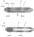
- (A) is a schematic longitudinal cross-sectional view which shows an example of embodiment of the heater of this invention
- (b) is the schematic perspective view which looked at the heater shown to (a) from the lower side toward the upper side.
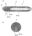
- (A) is a schematic perspective view showing another example of the heater
- (b) is a schematic cross-sectional view taken along the line AA shown in (a).
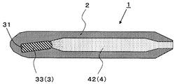
- It is a schematic perspective view which shows the other example of a heater.
- a heater 1 shown in FIG. 1 includes an insulating base 2, a heating element 3 embedded in the insulating base 2, and leads 4 embedded in the insulating base 2 and connected to the heating element 3. Inclined with respect to the lead 4.
- the heating element 3 includes a first straight portion 32, a second straight portion 33 provided in parallel with the first straight portion 32, and a folded portion 31 that connects the first straight portion 32 and the second straight portion 33.
- the lead 4 includes a first lead 41 connected to the first straight portion 32 and a second lead 42 connected to the second straight portion 33.
- the first straight portion 32 is inclined with respect to the first lead 41.
- the second straight portion 33 is inclined with respect to the second lead 42.
- the insulating base 2 in the heater 1 of the present embodiment is formed in a rod shape, for example.
- a heating element 3 and leads 4 are embedded in the insulating base 2.
- the insulating base 2 in this example is made of ceramics. Thereby, it becomes possible to provide the heater 1 with high reliability at the time of rapid temperature rise.
- the insulating substrate 2 in this example includes electrically insulating ceramics such as oxide ceramics, nitride ceramics or carbide ceramics.
- the insulating base 2 is preferably made of silicon nitride ceramics.
- silicon nitride ceramics silicon nitride as a main component is excellent in terms of high strength, high toughness, high insulation and heat resistance.
- the insulating base 2 made of a silicon nitride ceramic is, for example, 3-12 mass% rare earth such as Y 2 O 3 , Yb 2 O 3 or Er 2 O 3 as a sintering aid with respect to silicon nitride as a main component. Element oxide and 0.5 to 3% by mass of Al 2 O 3 are added, and SiO 2 is further mixed so that the amount of SiO 2 contained in the sintered body is 1.5 to 5% by mass. And then hot-press baked at 1650 to 1780 ° C.
- the length of the insulating base 2 is, for example, 20 to 50 mm, and the diameter of the insulating base 2 is, for example, 3 to 5 mm.
- the heating element 3 is embedded in the front end side of the insulating base 2.
- the distance from the front end of the heat generating element 3 (near the intermediate point of the folded portion 31) to the rear end of the heat generating element 3 (connecting portion with the lead 4) is, for example, 2 to 10 mm.
- the shape of the cross section of the heat generating body 3 can be a circle, an ellipse, or a rectangle.
- the heating element 3 is formed to have a smaller cross-sectional area than a lead 4 described later.
- the material for forming the heating element 3 a material mainly composed of a carbide such as W, Mo or Ti, a nitride or a silicide can be used.
- a carbide such as W, Mo or Ti
- a nitride or a silicide can be used.
- the insulating substrate 2 is made of silicon nitride ceramics
- tungsten carbide is one of the above materials because it has a small difference in thermal expansion coefficient from the insulating substrate 2, has high heat resistance, and has low specific resistance.
- (WC) is excellent as a material for the heating element 3.
- the heating element 3 is mainly composed of WC of an inorganic conductor, and the content of silicon nitride added thereto is 20% by mass or more. preferable.
- the conductor component serving as the heating element 3 has a higher coefficient of thermal expansion than silicon nitride, so that a tensile stress from the insulating base 2 is usually applied to the heating element 3. It is in the state.
- the thermal expansion coefficient of the heating element 3 can be brought close to the thermal expansion coefficient of the insulating substrate 2. Thereby, the thermal stress which arises between the heat generating body 3 and the insulation base body 2 at the time of temperature rising of the heater 1 and temperature fall can be relieved.
- the first lead 41 of the leads 4 is connected to the first linear portion 32 on one end side and led out from the side surface near the rear end of the insulating base 2 on the other end side.
- the second lead 42 is connected to the second linear portion 33 on one end side and led out from the rear end portion of the insulating base 2 on the other end side.
- the lead 4 is formed using the same material as the heating element 3.
- the lead 4 has a lower resistance per unit length by making the cross-sectional area larger than that of the heating element 3 or by making the content of the forming material of the insulating base 2 smaller than that of the heating element 3. ing.
- WC is suitable as a material for the lead 4 in that the difference in coefficient of thermal expansion from the insulating substrate 2 is small, the heat resistance is high, and the specific resistance is small.
- the lead 4 is preferably composed of WC, which is an inorganic conductor, as a main component, and silicon nitride is added to the lead 4 so that the content is 15% by mass or more.
- the first straight portion 32 is inclined with respect to the first lead 41.
- the heat generation in the folded portion 31 is larger than the heat generation in the first straight portion 32, and thus the amount of heat generated by the heating element 3 is biased. Arise. This is because even if the resistance values per unit length of the folded portion 31 and the first linear portion 32 are the same, the folded portion 31 that is inclined with respect to the direction of the electric flow is more resistant to the inrush current. It is assumed that the load is large. Therefore, in the heater 1 of this example, the load for the inrush current is increased also in the first linear portion 32 by inclining the first linear portion 32 with respect to the first lead 41.
- the emitted-heat amount in the 1st linear part 32 can be enlarged, the bias
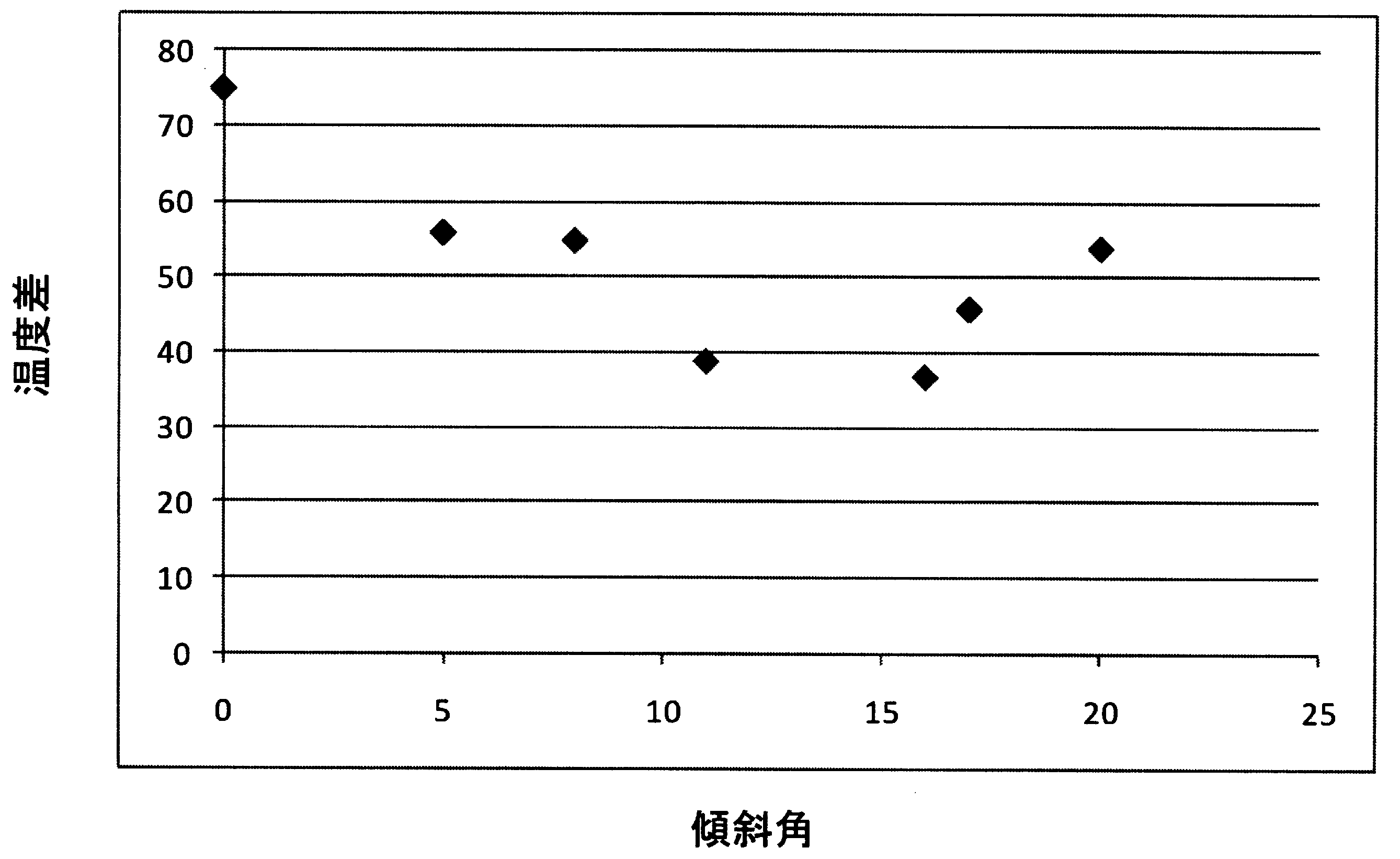
- the above-described effects can be obtained by inclining the first straight portion 32 with respect to the first lead 41 by 5 to 20 °.
- the temperature difference in the heating element 3 can be further reduced by tilting by 11 to 16 °.
- the heating element 3 includes a first straight part 32, a second straight part 33, and a folded part 31.
- a first lead 41 and a second lead 42 are connected to the first straight portion 32 and the second straight portion 33, respectively.
- the first lead 41 and the second lead 42 are provided in parallel except for a portion drawn out from the insulating base 2 to the outside.
- the first straight portion 32 is connected to be inclined with respect to the first lead 41.
- the second straight portion 33 is connected to be inclined with respect to the second lead 42. Since the second linear portion 33 is also inclined with respect to the second lead 42, the temperature difference in the heating element 3 can be further reduced.
- the first straight portion 32 and the second straight portion 33 are inclined with respect to a plane including the axes of both the first lead 41 and the second lead 42. Accordingly, the first straight portion 32 can be inclined with respect to the first lead 41 while maintaining the distance between the first straight portion 32 and the second straight portion 33. As a result, the possibility that a short circuit occurs between the first straight part 32 and the second straight part 33 can be reduced.
- the first straight portion 32 is inclined downward in FIG. 2A with respect to the first lead 41, and the second straight portion 33 is the second lead. 42 is inclined upward in FIG.
- the first straight portion 32 and the second straight portion 33 are inclined in different directions, so that the heater is compared with the case where the first straight portion 32 and the second straight portion 33 are inclined in the same direction. 1 can reduce the uneven distribution of heat in the circumferential direction of the insulating base 2.
- the second straight portion 33 is inclined with respect to the second lead 42, and the connection portion of the second straight portion 33 with the second lead 42 is a second straight line. It is thinner than other parts of the portion 33. Thereby, the cross-sectional area of the connection part with the 2nd lead 42 among the 2nd linear parts 33 is small compared with the other site
- FIG. Although not shown in FIG. 3, also with respect to the first straight part 32, the part connected to the first lead 41 in the first straight part 32 is compared with other parts of the first straight part 32. It is getting thinner.
- the heater 1 described above can be used as a glow plug 10 provided with a metal holding member 5 for holding the heater 1 as shown in FIG.
- the metal holding member 5 is a metal cylindrical body that holds the heater 1.
- the metal holding member 5 is joined and electrically connected to one first lead 41 drawn out to the side surface of the insulating base 2 with a brazing material or the like.
- the glow plug 10 is used by connecting external electrodes to the metal holding member 5 and the second lead 42.
- the heater 1 of the present embodiment can be formed by, for example, an injection molding method using a mold having the shape of the heating element 3, the lead 4, and the insulating base 2.
- a conductive paste that is a material of the heating element 3 and the lead 4 including the conductive ceramic powder and a resin binder is manufactured, and a ceramic paste that is a material of the insulating substrate 2 that includes the insulating ceramic powder and the resin binder. Is made.
- a conductive paste molded body having a predetermined pattern to be the heating element 3 is formed by an injection molding method or the like using the conductive paste. Then, with the heating element 3 held in the mold, the conductive paste is filled in the mold to form a conductive paste molded body having a predetermined pattern to be the leads 4. As a result, the heating element 3 and the leads 4 connected to the heating element 3 are held in the mold. At this time, the heating element 3 and the lead 4 of the fired heater 1 can be inclined by inclining the heating element 3 with respect to the lead 4.
- the obtained molded body is fired at, for example, a temperature of 1650 ° C. to 1780 ° C. and a pressure of 30 MPa to 50 MPa, whereby the heater 1 can be manufactured.
- the firing is performed in a non-oxidizing gas atmosphere such as hydrogen gas.
- the heater of the example of the present invention was manufactured as follows.
- a conductive paste containing 50% by mass of tungsten carbide (WC) powder, 35% by mass of silicon nitride (Si 3 N 4 ) powder, and 15% by mass of a resin binder is injection-molded into a mold and is shown in FIG. A heating element having a shape as shown was produced.
- the heating elements 3 were inclined with respect to the leads 4 for the samples 1 to 6 as the heaters of the example of the present invention. Specifically, in the samples 1 to 6, the first linear portion 32 and the second linear portion 33 are inclined so as to be inclined with respect to a plane including the axes of both the first lead 41 and the second lead 42. . Further, as a comparative example, a heater in which the heating element 3 is not inclined with respect to the lead 4 was also produced.
- the obtained heater 1 is put into a cylindrical carbon mold, it is sintered by performing hot pressing at a temperature of 1700 ° C. and a pressure of 35 Mpa in a non-oxidizing gas atmosphere made of nitrogen gas. I let you. A heater was produced as described above.
- the first straight portion 32 and the second straight portion 33 are in a plane including the axes of both the first lead 41 and the second lead 42. And inclined. Specifically, sample 1 was tilted at 5 °, sample 2 at 8 °, sample 3 at 11 °, sample 4 at 16 °, sample 5 at 17 °, and sample 6 at 20 °. . In the comparative example, neither the first straight part 32 nor the second straight part 33 was inclined.
- the dimensions of the heating element 3 are 0.4 mm in width and 0.9 mm in thickness, and the length in the axial direction of the insulating base 2 in the region where the heating element 3 is provided is about 4.5 mm.
- the vicinity of the folded portion 31 is 1203 ° C.
- the vicinity of the connection portion is 1128 ° C.
- a temperature difference of 75 ° C. is generated.
- the temperature difference between the vicinity of the folded portion 31 and the vicinity of the connection portion is reduced to 37 to 56 ° C. This is mainly because the temperature in the vicinity of the connection portion in Samples 1 to 6 is higher than the temperature in the vicinity of the connection portion in the comparative example. From the above results, the amount of heat generated in the first straight portion 32 and the second straight portion 33 can be increased by inclining the heat generating body 3 with respect to the lead 4, and the uneven amount of heat generated in the heat generating body 3 is reduced. I was able to confirm that it was possible.
- Table 2 shows the relationship between the inclination angle and the temperature difference between the vicinity of the folded portion 31 and the vicinity of the connection portion.
- Heater 10 Glow plug 2: Insulating substrate 3: Heating element 31: Folded portion 32: First straight portion 33: Second straight portion 4: Lead 41: First lead 42: Second lead
Landscapes
- Engineering & Computer Science (AREA)
- Chemical & Material Sciences (AREA)
- Combustion & Propulsion (AREA)
- Mechanical Engineering (AREA)
- General Engineering & Computer Science (AREA)
- Resistance Heating (AREA)
Abstract
Description

10:グロープラグ
2:絶縁基体
3:発熱体
31:折返し部
32:第1直線部
33:第2直線部
4:リード
41:第1リード
42:第2リード
Claims (6)
- 絶縁基体と、該絶縁基体に埋設された、第1直線部、該第1直線部と並行に設けられた第2直線部および前記第1直線部と前記第2直線部とを繋ぐ折返し部から成る発熱体と、前記絶縁基体に埋設されるとともに前記第1直線部に接続された第1リードと、前記絶縁基体に埋設されるとともに前記第2直線部に接続された第2リードとを備え、前記第1直線部が前記第1リードに対して傾斜しているヒータ。
- 前記第2直線部が前記第2リードに対して傾斜している請求項1に記載のヒータ。
- 前記第1直線部および前記第2直線部が、前記第1リードおよび前記第2リードの両方の軸を含む平面に対して傾斜している請求項1に記載のヒータ。
- 前記第1直線部および前記第2直線部が、前記第1リードおよび前記第2リードの両方の軸を含む平面に対して5~20°度傾斜している請求項3に記載のヒータ。
- 前記第1直線部および前記第2直線部が、前記第1リードおよび前記第2リードの両方の軸を含む平面に対して11~16°度傾斜している請求項3に記載のヒータ。
- 請求項1乃至請求項5のうちのいずれかに記載のヒータと、前記ヒータを保持する金属製保持部材とを備えたグロープラグ。
Priority Applications (4)
| Application Number | Priority Date | Filing Date | Title |
|---|---|---|---|
| JP2014544532A JP5969621B2 (ja) | 2012-10-29 | 2013-10-29 | ヒータおよびこれを備えたグロープラグ |
| CN201380050457.7A CN104662998B (zh) | 2012-10-29 | 2013-10-29 | 加热器以及具备该加热器的电热塞 |
| EP13850308.1A EP2914057B1 (en) | 2012-10-29 | 2013-10-29 | Heater and glow plug equipped with same |
| US14/434,011 US9651257B2 (en) | 2012-10-29 | 2013-10-29 | Heater and glow plug equipped with same |
Applications Claiming Priority (2)
| Application Number | Priority Date | Filing Date | Title |
|---|---|---|---|
| JP2012238086 | 2012-10-29 | ||
| JP2012-238086 | 2012-10-29 |
Publications (1)
| Publication Number | Publication Date |
|---|---|
| WO2014069480A1 true WO2014069480A1 (ja) | 2014-05-08 |
Family
ID=50627382
Family Applications (1)
| Application Number | Title | Priority Date | Filing Date |
|---|---|---|---|
| PCT/JP2013/079312 Ceased WO2014069480A1 (ja) | 2012-10-29 | 2013-10-29 | ヒータおよびこれを備えたグロープラグ |
Country Status (5)
| Country | Link |
|---|---|
| US (1) | US9651257B2 (ja) |
| EP (1) | EP2914057B1 (ja) |
| JP (2) | JP5969621B2 (ja) |
| CN (1) | CN104662998B (ja) |
| WO (1) | WO2014069480A1 (ja) |
Cited By (2)
| Publication number | Priority date | Publication date | Assignee | Title |
|---|---|---|---|---|
| JP2017010830A (ja) * | 2015-06-24 | 2017-01-12 | 日本特殊陶業株式会社 | セラミックヒータ及びその製造方法、並びにグロープラグ及びその製造方法 |
| WO2017090313A1 (ja) * | 2015-11-27 | 2017-06-01 | 京セラ株式会社 | ヒータおよびこれを備えたグロープラグ |
Families Citing this family (2)
| Publication number | Priority date | Publication date | Assignee | Title |
|---|---|---|---|---|
| JP6951126B2 (ja) * | 2017-05-26 | 2021-10-20 | 日本特殊陶業株式会社 | セラミックヒータ及びグロープラグ |
| CN111134375A (zh) * | 2020-01-19 | 2020-05-12 | 深圳市博迪科技开发有限公司 | 一种注塑成型的发热组件、注塑模具和注塑方法 |
Citations (4)
| Publication number | Priority date | Publication date | Assignee | Title |
|---|---|---|---|---|
| JPH07217886A (ja) * | 1994-02-07 | 1995-08-18 | Isuzu Ceramics Kenkyusho:Kk | 自己制御型セラミックグロープラグ |
| JP2001241660A (ja) * | 2000-02-29 | 2001-09-07 | Ngk Spark Plug Co Ltd | セラミックヒータ及びそのセラミックヒータを用いたグロープラグ |
| WO2011065366A1 (ja) * | 2009-11-27 | 2011-06-03 | 京セラ株式会社 | セラミックヒータ |
| WO2012118100A1 (ja) * | 2011-02-28 | 2012-09-07 | 京セラ株式会社 | ヒータおよびこれを備えたグロープラグ |
Family Cites Families (9)
| Publication number | Priority date | Publication date | Assignee | Title |
|---|---|---|---|---|
| JP3044630B2 (ja) * | 1991-02-06 | 2000-05-22 | ボッシュ ブレーキ システム株式会社 | セラミックヒータ型グロープラグ |
| DE19930334C2 (de) * | 1999-07-02 | 2003-07-31 | Beru Ag | Keramischer Heizstab und diesen enthaltende Glühkerze und Verfahren zu dessen Herstellung |
| JP4068309B2 (ja) * | 2001-03-02 | 2008-03-26 | 日本特殊陶業株式会社 | ヒータ及びその製造方法 |
| KR100915576B1 (ko) | 2004-05-27 | 2009-09-07 | 쿄세라 코포레이션 | 세라믹 히터 및 그것을 사용한 글로우 플러그 |
| EP1612486B1 (en) * | 2004-06-29 | 2015-05-20 | Ngk Spark Plug Co., Ltd | Glow plug |
| EP1998596B1 (en) * | 2006-03-21 | 2017-05-10 | NGK Spark Plug Co., Ltd. | Ceramic heater and glow plug |
| JP5438961B2 (ja) | 2008-02-20 | 2014-03-12 | 日本特殊陶業株式会社 | セラミックヒータ及びグロープラグ |
| JP5292317B2 (ja) * | 2008-02-20 | 2013-09-18 | 日本特殊陶業株式会社 | セラミックヒータ及びグロープラグ |
| JP5279447B2 (ja) * | 2008-10-28 | 2013-09-04 | 京セラ株式会社 | セラミックヒータ |
-
2013
- 2013-10-29 CN CN201380050457.7A patent/CN104662998B/zh active Active
- 2013-10-29 EP EP13850308.1A patent/EP2914057B1/en active Active
- 2013-10-29 WO PCT/JP2013/079312 patent/WO2014069480A1/ja not_active Ceased
- 2013-10-29 JP JP2014544532A patent/JP5969621B2/ja active Active
- 2013-10-29 US US14/434,011 patent/US9651257B2/en active Active
-
2016
- 2016-07-04 JP JP2016132568A patent/JP6337046B2/ja active Active
Patent Citations (4)
| Publication number | Priority date | Publication date | Assignee | Title |
|---|---|---|---|---|
| JPH07217886A (ja) * | 1994-02-07 | 1995-08-18 | Isuzu Ceramics Kenkyusho:Kk | 自己制御型セラミックグロープラグ |
| JP2001241660A (ja) * | 2000-02-29 | 2001-09-07 | Ngk Spark Plug Co Ltd | セラミックヒータ及びそのセラミックヒータを用いたグロープラグ |
| WO2011065366A1 (ja) * | 2009-11-27 | 2011-06-03 | 京セラ株式会社 | セラミックヒータ |
| WO2012118100A1 (ja) * | 2011-02-28 | 2012-09-07 | 京セラ株式会社 | ヒータおよびこれを備えたグロープラグ |
Cited By (2)
| Publication number | Priority date | Publication date | Assignee | Title |
|---|---|---|---|---|
| JP2017010830A (ja) * | 2015-06-24 | 2017-01-12 | 日本特殊陶業株式会社 | セラミックヒータ及びその製造方法、並びにグロープラグ及びその製造方法 |
| WO2017090313A1 (ja) * | 2015-11-27 | 2017-06-01 | 京セラ株式会社 | ヒータおよびこれを備えたグロープラグ |
Also Published As
| Publication number | Publication date |
|---|---|
| JP6337046B2 (ja) | 2018-06-06 |
| US9651257B2 (en) | 2017-05-16 |
| CN104662998A (zh) | 2015-05-27 |
| US20150241060A1 (en) | 2015-08-27 |
| JP2016184592A (ja) | 2016-10-20 |
| EP2914057B1 (en) | 2017-12-20 |
| EP2914057A1 (en) | 2015-09-02 |
| JP5969621B2 (ja) | 2016-08-17 |
| EP2914057A4 (en) | 2016-05-25 |
| CN104662998B (zh) | 2016-08-24 |
| JPWO2014069480A1 (ja) | 2016-09-08 |
Similar Documents
| Publication | Publication Date | Title |
|---|---|---|
| EP2600688B1 (en) | Heater and glow plug provided with same | |
| JP6337046B2 (ja) | ヒータおよびこれを備えたグロープラグ | |
| JP5289462B2 (ja) | セラミックヒータ | |
| JPWO2012099232A1 (ja) | ヒータおよびこれを備えたグロープラグ | |
| US20140053795A1 (en) | Heater and glow plug provided with same | |
| JP5777812B2 (ja) | ヒータおよびこれを備えたグロープラグ | |
| JP5436687B2 (ja) | ヒータおよびこれを備えたグロープラグ | |
| JP2013038003A (ja) | ヒータおよびこれを備えたグロープラグ | |
| JP5726311B2 (ja) | ヒータおよびこれを備えたグロープラグ | |
| JP6105464B2 (ja) | ヒータおよびこれを備えたグロープラグ | |
| JP6085050B2 (ja) | ヒータおよびこれを備えたグロープラグ |
Legal Events
| Date | Code | Title | Description |
|---|---|---|---|
| 121 | Ep: the epo has been informed by wipo that ep was designated in this application |
Ref document number: 13850308 Country of ref document: EP Kind code of ref document: A1 |
|
| ENP | Entry into the national phase |
Ref document number: 2014544532 Country of ref document: JP Kind code of ref document: A |
|
| WWE | Wipo information: entry into national phase |
Ref document number: 14434011 Country of ref document: US Ref document number: 2013850308 Country of ref document: EP |
|
| NENP | Non-entry into the national phase |
Ref country code: DE |