WO2014069570A1 - 非空気入りタイヤ - Google Patents
非空気入りタイヤ Download PDFInfo
- Publication number
- WO2014069570A1 WO2014069570A1 PCT/JP2013/079550 JP2013079550W WO2014069570A1 WO 2014069570 A1 WO2014069570 A1 WO 2014069570A1 JP 2013079550 W JP2013079550 W JP 2013079550W WO 2014069570 A1 WO2014069570 A1 WO 2014069570A1
- Authority
- WO
- WIPO (PCT)
- Prior art keywords
- tire
- ring
- connecting plate
- pneumatic tire
- circumferential direction
- Prior art date
- Legal status (The legal status is an assumption and is not a legal conclusion. Google has not performed a legal analysis and makes no representation as to the accuracy of the status listed.)
- Ceased
Links
Images


Classifications
-
- B—PERFORMING OPERATIONS; TRANSPORTING
- B60—VEHICLES IN GENERAL
- B60B—VEHICLE WHEELS; CASTORS; AXLES FOR WHEELS OR CASTORS; INCREASING WHEEL ADHESION
- B60B9/00—Wheels of high resiliency, e.g. with conical interacting pressure-surfaces
- B60B9/02—Wheels of high resiliency, e.g. with conical interacting pressure-surfaces using springs resiliently mounted bicycle rims
- B60B9/04—Wheels of high resiliency, e.g. with conical interacting pressure-surfaces using springs resiliently mounted bicycle rims in leaf form
-
- B—PERFORMING OPERATIONS; TRANSPORTING
- B60—VEHICLES IN GENERAL
- B60C—VEHICLE TYRES; TYRE INFLATION; TYRE CHANGING; CONNECTING VALVES TO INFLATABLE ELASTIC BODIES IN GENERAL; DEVICES OR ARRANGEMENTS RELATED TO TYRES
- B60C7/00—Non-inflatable or solid tyres
- B60C7/10—Non-inflatable or solid tyres characterised by means for increasing resiliency
- B60C7/14—Non-inflatable or solid tyres characterised by means for increasing resiliency using springs
- B60C7/16—Non-inflatable or solid tyres characterised by means for increasing resiliency using springs of helical or flat coil form
- B60C7/18—Non-inflatable or solid tyres characterised by means for increasing resiliency using springs of helical or flat coil form disposed radially relative to wheel axis
-
- B—PERFORMING OPERATIONS; TRANSPORTING
- B60—VEHICLES IN GENERAL
- B60B—VEHICLE WHEELS; CASTORS; AXLES FOR WHEELS OR CASTORS; INCREASING WHEEL ADHESION
- B60B9/00—Wheels of high resiliency, e.g. with conical interacting pressure-surfaces
- B60B9/02—Wheels of high resiliency, e.g. with conical interacting pressure-surfaces using springs resiliently mounted bicycle rims
- B60B9/08—Wheels of high resiliency, e.g. with conical interacting pressure-surfaces using springs resiliently mounted bicycle rims in flat coiled form
-
- B—PERFORMING OPERATIONS; TRANSPORTING
- B60—VEHICLES IN GENERAL
- B60B—VEHICLE WHEELS; CASTORS; AXLES FOR WHEELS OR CASTORS; INCREASING WHEEL ADHESION
- B60B9/00—Wheels of high resiliency, e.g. with conical interacting pressure-surfaces
- B60B9/26—Wheels of high resiliency, e.g. with conical interacting pressure-surfaces comprising resilient spokes
-
- B—PERFORMING OPERATIONS; TRANSPORTING
- B60—VEHICLES IN GENERAL
- B60C—VEHICLE TYRES; TYRE INFLATION; TYRE CHANGING; CONNECTING VALVES TO INFLATABLE ELASTIC BODIES IN GENERAL; DEVICES OR ARRANGEMENTS RELATED TO TYRES
- B60C7/00—Non-inflatable or solid tyres
- B60C7/10—Non-inflatable or solid tyres characterised by means for increasing resiliency
- B60C7/14—Non-inflatable or solid tyres characterised by means for increasing resiliency using springs
- B60C7/146—Non-inflatable or solid tyres characterised by means for increasing resiliency using springs extending substantially radially, e.g. like spokes
-
- B—PERFORMING OPERATIONS; TRANSPORTING
- B60—VEHICLES IN GENERAL
- B60C—VEHICLE TYRES; TYRE INFLATION; TYRE CHANGING; CONNECTING VALVES TO INFLATABLE ELASTIC BODIES IN GENERAL; DEVICES OR ARRANGEMENTS RELATED TO TYRES
- B60C7/00—Non-inflatable or solid tyres
- B60C7/24—Non-inflatable or solid tyres characterised by means for securing tyres on rim or wheel body
Definitions
- the present invention relates to a non-pneumatic tire that does not need to be filled with pressurized air when used.
- Patent Document 1 In order to solve such problems, in recent years, for example, a non-pneumatic tire as shown in Patent Document 1 has been proposed.
- the present invention has been made in consideration of such circumstances, and an object of the present invention is to provide a non-pneumatic tire capable of ensuring sufficient strength while suppressing an increase in weight.
- the thickness of the largest curved portion having the largest central angle is the largest among the curved portions of one connecting plate, which is greatly bent and deformed.
- the thickness of the minimum bending portion with the smallest central angle is minimum because it is difficult to bend and deform and is difficult to be loaded. Therefore, sufficient strength can be easily secured while suppressing an increase in weight.
- the connecting part is connected to the connecting part because the bending part connected to the one end where the load is most likely to be applied is the maximum bending part.
- the strength of the plate can be effectively increased.
- the bending portion located at the intermediate portion is the minimum bending portion, it is possible to reliably ensure a sufficient strength while suppressing an increase in weight.
- a non-pneumatic tire according to a third aspect of the present invention is the above-described first or second aspect, wherein one end portion and the other end portion of the intermediate portions of the first connection plate and the second connection plate are separately provided.
- the continuous curved portions are opposite to each other in the direction of protrusion in the tire circumferential direction. For this reason, when an external force is applied to the non-pneumatic tire, the first connecting plate and the second connecting plate can be easily elastically deformed. Comfort can be secured.
- the exterior body, the ring-shaped body, and the plurality of connecting members are integrally formed.
- both ends of each of the plurality of connecting members are attached in a state in which the ring-shaped body and the plurality of connecting members are integrally formed without being connected to the exterior body and the ring-shaped body. Since it is sufficient to attach to the body, the manufacturing time can be shortened.
- the ring-shaped body and the plurality of connecting members are integrally formed, for example, the weight of the both ends of the connecting member and the exterior body and the ring-shaped body are compared with the case of connecting using a fastening member or the like. Can be suppressed.
- the connection part of a connection member and a ring-shaped body is integrally formed, compared with the case where both are connected using a fastening member etc., stress concentration can be eased.
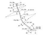
- FIG. 5 is an enlarged view showing a connecting plate of the present embodiment (Example 1), which is a non-pneumatic tire having a tire size of 3.00-8.
- FIG. 3 is an enlarged view showing a connecting plate of Comparative Example 1 which is a non-pneumatic tire having a tire size of 3.00-8.
- FIG. 5 is an enlarged view showing a connecting plate of the present embodiment (Example 2), which is a non-pneumatic tire having a tire size of 4.00-5.
- FIG. 5 is an enlarged view showing a connecting plate of Comparative Example 2 which is a non-pneumatic tire having a tire size of 4.00-5.
- the non-pneumatic tire 1 of the present embodiment may be employed in a small vehicle that travels at a low speed, such as a handle-type electric wheelchair defined in Japanese Industrial Standard JIS T 9208.
- a non-pneumatic tire 1 having a tire size of, for example, 3.00-8 will be described.
- the non-pneumatic tire 1 of the present embodiment includes an attachment body 11 attached to an axle (not shown), a ring-like body 13 surrounding the attachment body 11 from the outside in the tire radial direction, and an attachment.
- a plurality of connecting members 15 that are disposed between the body 11 and the ring-shaped body 13 along the tire circumferential direction, and that connect the attachment body 11 and the ring-shaped body 13 so as to be relatively elastically displaceable. And a tread member 16 disposed on the outer peripheral surface side of the ring-shaped body 13 over the entire circumference thereof.
- the attachment body 11, the ring-shaped body 13, and the tread member 16 are each arranged coaxially with the common shaft.
- the common axis is referred to as an axis O
- a direction along the axis O is referred to as a tire width direction H
- a direction orthogonal to the axis O is referred to as a tire radial direction
- a direction around the axis O is referred to as a tire circumferential direction.
- the attachment body 11, the ring-shaped body 13, and the tread member 16 are disposed such that the center portions in the tire width direction H are aligned with each other.
- the attachment body 11 connects the mounting cylinder part 17 to which the front end part of the axle is mounted, the outer ring part 18 surrounding the mounting cylinder part 17 from the outer side in the tire radial direction, and the mounting cylinder part 17 and the outer ring part 18.
- a plurality of ribs 19 are integrally formed of a metal material such as an aluminum alloy.
- the mounting cylinder portion 17 and the outer ring portion 18 are each formed in a cylindrical shape and are arranged coaxially with the axis O.
- the plurality of ribs 19 are arranged point-symmetrically with respect to the axis O.
- a plurality of key groove portions 18a that are recessed toward the inside in the tire radial direction and that extend in the tire width direction H are formed on the outer peripheral surface of the outer ring portion 18 at intervals in the tire circumferential direction.
- the key groove portion 18 a is opened only on one side of both ends in the tire width direction H on the outer peripheral surface of the outer ring portion 18, and the other side is closed.
- a plurality of hollow holes penetrating in the tire radial direction are arranged at intervals in the tire width direction H in a portion located between the key groove portions 18 a adjacent in the tire circumferential direction.
- a plurality of hole rows 18c are formed at intervals in the tire circumferential direction.
- the rib 19 is also formed with a hole 19a penetrating in the tire width direction H.
- a concave portion 18b that is recessed toward the other side in the tire width direction H and into which the plate material 28 is fitted is formed at the edge corresponding to the key groove portion 18a at one edge of the outer ring portion 18 in the tire width direction H.
- a through hole is formed in the plate material 28 and communicates with a through hole of the plate material 28 fitted in the recess 18b on a bottom wall surface facing one side in the tire width direction H among the wall surfaces defining the recess 18b.
- An internal thread portion is formed. A plurality of these internal thread portions and through holes are formed at intervals in the tire circumferential direction.
- a cylindrical exterior body 12 is externally fitted to the attachment body 11.
- a plurality of protrusions 12 a that protrude toward the inner side in the tire radial direction and extend over the entire length in the tire width direction H are disposed at intervals in the tire circumferential direction.
- These protrusions 12a are fitted in the key groove portions 18a of the attachment body 11, respectively.
- the exterior body 12 is fixed to the attachment body 11 by fixing the plate material 28 in the recess 18b in a state in which the protruding portion 12a is fitted in the key groove portion 18a. In this state, the protrusion 12a is sandwiched between the plate member 28 and the bottom wall surface of the recess 18b in the tire width direction H.
- the pair of side wall surfaces and the bottom wall surface facing each other in the tire circumferential direction form a right angle.
- a pair of side wall surfaces which stand up from the inner peripheral surface of the exterior body 12 and the top wall surface which faces the inner side in the tire radial direction out of the outer surface of the protruding portion 12a form a right angle.
- the size of the protrusion 12a and the key groove 18a in the tire circumferential direction is equal to each other.
- the ring-shaped body 13 is larger in size in the tire width direction H than the exterior body 12, that is, the width is larger. In the example shown in the figure, the ring-shaped body 13 is formed in a cylindrical shape.
- the connecting member 15 connects the outer peripheral surface side of the mounting body 11 and the inner peripheral surface side of the ring-shaped body 13.
- the connecting member 15 is connected to the outer peripheral surface of the exterior body 12 and the ring-shaped body.
- the first connecting plate 21 and the second connecting plate 22 that are elastically deformable and connect the inner peripheral surface of the first connecting plate 13 to each other.
- a plurality of first connecting plates 21 are arranged along a tire circumferential direction at predetermined positions along one tire width direction H (one side along the tire width direction H), and the second connecting plate 22. Are arranged along the tire circumferential direction at other positions along the tire width direction H (the other side along the tire width direction H) different from the predetermined position along one tire width direction H.
- the plurality of first connecting plates 21 are arranged in the tire circumferential direction H at the same position along the tire circumferential direction, and the plurality of second connecting plates 22 extend from the first connecting plate 21 in the tire width direction.
- a plurality of tires are arranged along a tire circumferential direction at predetermined positions along the same tire width direction H apart from H.
- 60 connecting plates 21 and 22 are provided along the tire circumferential direction.
- the plurality of connecting members 15 are separately disposed between the exterior body 12 and the ring-shaped body 13 at positions that are point-symmetric with respect to the axis O. All the connecting members 15 have the same shape and the same size. Further, the width of the connecting member 15 is smaller than the width of the ring-shaped body 13. And in the state where the compressive load is not acting in the tire radial direction, the first connecting plates 21 adjacent in the tire circumferential direction are not in contact with each other. Similarly, the second connecting plates 22 adjacent in the tire circumferential direction are not in contact with each other in a state where a compressive load is not acting in the tire radial direction. Further, the first connecting plate 21 and the second connecting plate 22 adjacent in the tire width direction H are not in contact with each other. The widths of the first connecting plate 21 and the second connecting plate 22 are equal to each other. The thicknesses of the first connecting plate 21 and the second connecting plate 22 are also equal to each other.
- one end portion 21 a connected to the ring-shaped body 13 of the first connecting plate 21 is one side in the tire circumferential direction with respect to the other end portion 21 b connected to the exterior body 12.
- one end 22 a connected to the ring-shaped body 13 is located on the other side in the tire circumferential direction with respect to the other end 22 b connected to the exterior body 12.
- the one end portions 21a and 22a of the first connecting plate 21 and the second connecting plate 22 in one connecting member 15 are different from each other in the tire width direction H on the inner peripheral surface of the ring-shaped body 13, It is connected to the same position in the tire circumferential direction.
- each of the first connecting plate 21 and the second connecting plate 22 intermediate portions 21c, 22c located between the one end portions 21a, 22a and the other end portions 21b, 22b are arranged in the tire circumferential direction.
- a plurality of curved portions 21d to 21j and 22d to 22j are formed along the direction in which the connecting plates 21 and 22 extend in the tire side view of the non-pneumatic tire 1 viewed from the tire width direction H (seven locations in the illustrated example). ) Is formed.
- the plurality of curved portions 21d to 21j formed on the first connecting plate 21 are curved with the first curved portion 21d curved so as to protrude toward the other side in the tire circumferential direction, and one in the tire circumferential direction.
- Second curved portion 21e curved to project toward the side
- third curved portion 21f and fourth curved portion 21g curved to project toward the other side in the tire circumferential direction, tire circumferential direction
- a fifth curved portion 21h that is curved so as to project toward one side of the tire
- a sixth curved portion 21i and a seventh curved portion 21j that are curved so as to project toward the other side in the tire circumferential direction. It forms in order along the extending direction mentioned above from the one end part 21a to the other end part 21b.
- the plurality of curved portions 22d to 22j formed on the second connecting plate 22 have a first curved portion 22d curved so as to project toward one side in the tire circumferential direction, and toward the other side in the tire circumferential direction.
- a second curved portion 22e that is curved so as to project, a third curved portion 22f and a fourth curved portion 22g that are curved so as to project toward one side in the tire circumferential direction, and the other side in the tire circumferential direction From the one end portion 22a, a fifth bending portion 22h that is curved to project toward the first curved portion, and a sixth curved portion 22i and a seventh curved portion 22j that are curved to project toward one side in the tire circumferential direction. It forms in order along the extending direction mentioned above over the other end part 22b.
- each of the connecting plates 21 and 22 among the plurality of bending portions 21d to 21j and 22d to 22j, the third bending portions 21f and 22f and the fourth bending portions 21g and 22g adjacent to each other in the extending direction described above,
- the bending directions of the sixth bending portions 21i and 22i and the seventh bending portions 21j and 22j are the same as each other, while the bending directions of the other bending portions are opposite to each other.
- the first curved portions 21d and 22d and the seventh curved portions 21j and 22j are curved in the same direction.
- the first curved portions 21d and 22d and the seventh curved portions 21j and 22j located at both ends in the extending direction described above are other curved portions located in the central portion in the extending direction.
- the radius of curvature in a side view of the tire is smaller than those of the portions 21e to 21i and 22e to 22i.
- the first bending portions 21d and 22d have the smallest curvature radius among the bending portions 21d to 21j and 22d to 22j.
- the thickness of the connecting plates 21 and 22 along the tire circumferential direction increases as the central angles ⁇ d to ⁇ j centering on the center of curvature increase. It has become.
- the first curved portions 21d and 22d connected to the one end portions 21a and 22a have the largest central angle ⁇ d and constitute the largest curved portion having the maximum thickness.
- the sixth bending portions 21i and 22i located at the intermediate portions 21c and 22c have the smallest central angle ⁇ i and the minimum bending portion having the smallest thickness.
- the first bending portions 21d and 22d (center angle ⁇ d is 70.5 °, for example), the second bending portions 21e and 22e (center angle ⁇ e is 33.0 °, for example), and the seventh bending portions 21j and 22j.
- Center angle ⁇ j is 27.4 °, for example
- fourth curved portions 21g, 22g center angle ⁇ g is 22.5 °, for example
- fifth curved portions 21h, 22h center angle ⁇ h is 17.4 °, for example
- the third bending portions 21f and 22f center angle ⁇ f is, for example, 15.7 °
- the sixth bending portions 21i, 22i center angle ⁇ i is, for example, 13.9 °
- the connecting portions between the curved portions 21d to 21j and 22d to 22j adjacent to each other have a thickness that gradually changes from one curved portion toward another curved portion adjacent to the one curved portion, for example. It has become. That is, the curved portions 21d to 21j and 22d to 22j adjacent to each other are smoothly connected without any step.
- the thicknesses of the curved portions 21d to 21j and 22d to 22j are set in the range of 0.1 mm or more and 5.0 mm or less, respectively.
- the thickness By setting the thickness to 0.1 mm or more, the strength of the connecting plates 21 and 22 can be secured.
- the thickness to 5.0 mm or less By setting the thickness to 5.0 mm or less, the flexibility of the connecting plates 21 and 22 can be secured, and the increase in weight is suppressed, and the sink when the connecting plates 21 and 22 are manufactured by injection molding. Can be suppressed.
- the lengths of the connecting plates 21 and 22 are equal to each other, and the other end portions 21b and 22b of the connecting plates 21 and 22 are externally seen from the side of the tire as shown in FIG.
- the same angle for example, 20 ° or more and 135 ° or less
- the curved portions 21d to 21j and 22d to 22j are opposite to each other in the protruding direction in the tire circumferential direction and have a size.
- each connecting member 15 in the tire side view is symmetrical with respect to an imaginary line L that extends along the tire radial direction and passes through the one end portions 21a and 22a of both connecting plates 21 and 22. Yes.
- the exterior body 12, the ring-shaped body 13, and the plurality of connecting members 15 are integrally formed. Furthermore, in this embodiment, as shown in FIG. 1, the exterior body 12 includes a one-side divided exterior body 25 located on one side in the tire width direction H and a second-side divided exterior located on the other side in the tire width direction H. The body 26 is divided. The ring-shaped body 13 is divided into a one-side split ring-shaped body 23 located on one side in the tire width direction H and a second-side split ring-shaped body 24 located on the other side in the tire width direction H. Yes. In the illustrated example, the exterior body 12 and the ring-shaped body 13 are each divided at the center in the tire width direction H.
- the one-side split exterior body 25 and the one-side split ring-shaped body 23 are formed integrally with the first connecting plate 21, and the other-side split exterior body 26 and the other-side split ring-shaped body 24 are the second connecting plate 22. And is integrally formed. Further, in the present embodiment, the one-side divided outer body 25, the one-side divided ring-shaped body 23 and the first connecting plate 21, and the other-side divided outer-body 26, the other-side divided ring-shaped body 24 and the second connecting plate 22 are respectively It is integrally formed by casting or injection molding.
- the one-side divided outer body 25, the one-side divided ring-like body 23, and the first connecting plate 21 are integrally formed as a first divided case body 31, the other-side divided outer body 26, and the other-side divided ring.
- the body 24 and the second connecting plate 22 that are integrally formed are referred to as a second divided case body 32.
- the injection molding may be a general method in which each of the divided case bodies 31 and 32 is molded at the same time, and each of the divided case bodies 31 and 32 has a respective divided exterior body 25. , 26, each of the split ring-like bodies 23, 24, and a part of each of the connecting plates 21, 22 may be insert molding in which the rest is injection molded, or so-called two-color molding may be used. .
- each division case body 31 and 32 each division
- this material examples include a metal material and a resin material, but a resin material, particularly a thermoplastic resin is preferable from the viewpoint of weight reduction.
- a plurality of protrusions 12a formed on the exterior body 12 may be used as gate portions.
- the exterior body 12 has a width smaller than that of the ring-shaped body 13 and is equal to each width of the first connection plate 21 and the second connection plate 22.
- segmentation ring-shaped body 23 and 24 is connected by welding, melt
- welding for example, hot plate welding or the like may be employed.
- the edges in the tire width direction H of each of the divided exterior bodies 25 and 26 are separated from each other in the tire width direction H. Thereby, it is prevented that a burr
- segmentation case body 31 and 32 is mutually the same shape and the same size as FIG. 3 shows in the state before connecting these 31 and 32 as mentioned above. And when connecting each division
- the tread member 16 is formed in a cylindrical shape and integrally covers the outer peripheral surface side of the ring-shaped body 13 over the entire region.
- the inner peripheral surface of the tread member 16 extends over the entire region and the outer peripheral surface of the ring-shaped body 13. Close to.
- the tread member 16 is made of, for example, vulcanized rubber obtained by vulcanizing natural rubber and / or a rubber composition, or a thermoplastic material.
- the thermoplastic material include a thermoplastic elastomer or a thermoplastic resin.
- thermoplastic elastomer examples include amide-based thermoplastic elastomer (TPA), ester-based thermoplastic elastomer (TPC), olefin-based thermoplastic elastomer (TPO), styrene-based thermoplastic elastomer (TPS), and urethane as defined in JIS K6418.
- TPA thermoplastic elastomer
- TPC ester-based thermoplastic elastomer
- TPO olefin-based thermoplastic elastomer
- TPS styrene-based thermoplastic elastomer
- urethane examples include urethane resin, olefin resin, vinyl chloride resin, and polyamide resin. From the viewpoint of wear resistance, it is preferable to form the tread member 16 from vulcanized rubber.
- the bending portions 21d to 21j and 22d to 22j in the one connecting plate 21 and 22 are greatly bent and easily loaded.
- the largest curved portion (for example, the first curved portions 21d and 22d) having the largest central angle is the largest, and the smallest curved portion (for example, the sixth curved portion) having the smallest central angle is difficult to bend and deform and difficult to be loaded.
- the thickness of the portions 21i, 22i) is minimized. Therefore, sufficient strength can be easily secured while suppressing an increase in weight.
- the first bending portions 21d and 22d that are continuous with the one end portions 21a and 22a that are most likely to be loaded are the maximum bending portions.
- the strength can be effectively increased.
- the sixth bending portions 21i and 22i located at the intermediate portions 21c and 22c are the minimum bending portions, it is possible to reliably ensure a sufficient strength while suppressing an increase in weight.
- the curved portions in the connecting portions respectively connected to the one end portions 21a and 22a and the other end portions 21b and 22b) (
- the first curved portions 21d and 22d and the seventh curved portions 21j and 22j) have opposite directions in which they protrude from each other in the tire circumferential direction. Therefore, when an external force is applied to the non-pneumatic tire 1, the first connecting plate 21 and the second connecting plate 22 can be easily elastically deformed, and the non-pneumatic tire 1 is provided with flexibility. And good ride comfort.
- first connecting plates 21 are arranged along the tire circumferential direction at a position in one tire width direction H
- second connecting plates 22 are arranged at other tire width direction H positions in the tire circumferential direction. Since a plurality of the connecting members 15 are arranged along the tire circumferential direction, it is possible to prevent the adjacent connecting members 15 from interfering with each other in the tire circumferential direction, and it is possible to suppress the restriction on the number of the arranged members.
- the connecting member 15 is formed symmetrically with respect to the virtual line L in a side view of the tire, the spring constant along one side in the tire circumferential direction and the spring constant along the other side in the non-pneumatic tire 1 Therefore, it is possible to suppress the difference between the two, and it is possible to provide good maneuverability.
- each end of each of the plurality of connecting members 15 is Even if it is not connected to the exterior body 12 and the ring-shaped body 13 separately, it is sufficient to attach the ring-shaped body 13 and the plurality of connecting members 15 to the mounting body 11 in an integrally formed state, so that the manufacturing time can be shortened. .
- the ring-shaped body 13 and the plurality of connecting members 15 are integrally formed, for example, both ends of the connecting member 15 are connected to the exterior body 12 and the ring-shaped body 13 using a fastening member or the like. The weight can be reduced compared to the case.
- the connection part of the connection member 15 and the ring-shaped body 13 is integrally formed, compared with the case where both are connected using a fastening member etc., stress concentration can be relieved.
- the non-pneumatic tire 1 having a tire size of, for example, 3.00-8 has been described.
- the present invention is not limited to this, and the present invention can be applied to non-pneumatic tires 1 of various sizes. It is.
- the non-pneumatic tire 1 having a tire size of, for example, 4.00-5 will be described.
- the same components as those in the above-described embodiment are denoted by the same reference numerals and description thereof is omitted.
- each of the first connecting plate 21 and the second connecting plate 22 intermediate portions 21c, 22c located between the one end portions 21a, 22a and the other end portions 21b, 22b are arranged in the tire circumferential direction.
- a plurality of curved portions 121d to 121k and 122d to 122k are formed along the direction in which the connecting plates 21 and 22 extend in the tire side view of the non-pneumatic tire 1 viewed from the tire width direction H (eight points in the illustrated example). ) Is formed.
- the plurality of curved portions 121d to 121k formed on the first connecting plate 21 are curved with the first curved portion 121d curved so as to protrude toward the other side in the tire circumferential direction and one in the tire circumferential direction.
- Eight curved portions 121k are formed in order along the extending direction described above from one end 21a to the other end 21b. It should be noted that the curved portions 122d to 122k of the second connecting plate 22 are opposite to the curved portions 121d to 121k of the first connecting plate 21 in the circumferential direction of the tire and have the same size. ing.
- Each of the curved portions 121d to 121k and 122d to 122k of the present embodiment is thicker in the tire circumferential direction as the central angles ⁇ d to ⁇ k centered on the center of curvature are larger, as in the above-described embodiment. ing. Specifically, among the curved portions 121d to 121k and 122d to 122k, the first curved portions 121d and 122d connected to the one end portions 21a and 22a have the largest central angle ⁇ d and constitute the largest curved portion having the maximum thickness. The second bending portions 121e and 122e located at the intermediate portions 21c and 22c have the smallest central angle ⁇ e and constitute the minimum bending portion with the smallest thickness.
- the first bending portions 121d and 122d (center angle ⁇ d is 68.48 °, for example), the fifth bending portions 121h and 122h (center angle ⁇ h is 43.6 °, for example), and the eighth bending portions 121k and 122k.
- Center angle ⁇ k is 27.2 °, for example
- fourth curved portions 121g, 122g center angle ⁇ g is 21.9 °, for example
- seventh curved portions 121j, 122j center angle ⁇ j is, for example, 13.0 °
- the third bending portions 121f and 122f center angle ⁇ f is 10.4 °, for example
- the sixth bending portions 121i and 122i center angle ⁇ i is 10.2 °, for example
- the second bending portions 21e and 22e center angle ⁇ e are
- the central angle is small in the order of 4.3 °)
- the thicknesses of the curved portions 121d to 121k and 122d to 122k are thin.
- this inventor performed the verification test which compares a weight and intensity
- Comparative Examples 1 and 2 of Examples 1 and 2 of Examples 1 and 2 as shown in FIGS. 5B and 6B, in the non-pneumatic tires of the same size as the corresponding Examples 1 and 2, tires of the connecting plates 21 and 22 A configuration was adopted in which the thickness along the circumferential direction was uniformly formed in the direction in which the connecting plates 21 and 22 extend.
- the thickness of the connection plates 21 and 22 of the comparative examples 1 and 2 is, for example, the average of the thicknesses of the connection plates 21 and 22 in the examples. Furthermore, in Comparative Examples 1 and 2 shown in FIGS. 5B and 6B, the same reference numerals are given to the portions corresponding to Examples 1 and 2.
- the non-pneumatic tires of each example can ensure sufficient strength after reducing the weight of each tire size compared to the non-pneumatic tires of each comparative example.
- the weight and strength of Comparative Example 1 were 100, in Example 1, the weight was 90 and the strength was 210.
- the weight and strength of Comparative Example 2 were 100, in Example 2, the weight was 93 and the strength was 135.
- each bending part is easily bent and deformed easily, and the thickness of the part having a large central angle is increased to ensure the strength, while bending deformation is difficult and the load is difficult to apply, and the central angle is small. This is probably because the increase in weight was suppressed by reducing the thickness of the portion.
- the bending direction of the bending portion in the first connecting plate 21 and the bending direction of the bending portion in the second connecting plate 22 are not limited to the above-described embodiment, and may be appropriately changed.
- the first curved portions 21d and 22d connected to the one end portions 21a and 22a are the largest curved portions, for example, the sixth curved portions 21i and 22i located at the intermediate portions 21c and 22c.
- the present invention is not limited to this, and the maximum bending portion and the minimum bending portion can be appropriately changed in design.
- connection member 15 may be arranged along the tire width direction H in three or more rows or in one row.
- a plurality of connecting members 15 may be provided along the tire width direction H between the exterior body 12 and the ring-shaped body 13.
- the other end portions 21b and 22b of the first connecting plate 21 and the second connecting plate 22 are opposite to each other, for example, with the axis O sandwiched in the tire radial direction on the outer peripheral surface of the exterior body 12 instead of the above-described embodiment. May be connected to each position separately, or on the outer peripheral surface of the exterior body 12, a position facing the one end portions 21 a, 22 a of the first connecting plate 21 and the second connecting plate 22 in the tire radial direction. Or the like.
- the one end portions 21 a and 22 a of both the connecting plates 21 and 22 may be connected to the inner peripheral surface of the ring-shaped body 13 with different positions in the tire circumferential direction.
- the exterior body 12 and the ring-shaped body 13 may be divided into three or more in the tire width direction H, or may not be divided.
- the first and second divided case bodies 31 and 32 are not limited to the above-described embodiment, and may be formed by, for example, cutting.
- the exterior body 12, the ring-shaped body 13, and the plurality of connecting members 15 are integrally formed.
- the present invention is not limited to this. You may connect.
- the exterior body 12 may be formed integrally with the attachment body 11.
- the configuration in which the one end portions 21 a and 22 a of the connecting member 15 are indirectly connected to the attachment body 11 via the exterior body 12 is described.
- the one end portions 21a and 22a of the member 15 may be directly connected.
- the non-pneumatic tire of the present invention can ensure sufficient strength while suppressing an increase in weight.
Landscapes
- Engineering & Computer Science (AREA)
- Mechanical Engineering (AREA)
- Tires In General (AREA)
Abstract
本発明の連結部材(15)は、取り付け体とリング状体(13)とを連結する連結板(21,22)を備え、連結板(21,22)には、タイヤ周方向に湾曲する湾曲部(21d~21j,22d~22j)が、タイヤ幅方向から見たタイヤ側面視で、連結板(21,22)が延びる方向に沿って複数形成され、1つの連結板(21,22)における複数の湾曲部(21d~21j,22d~22j)のうち、それぞれの湾曲部(21d~21j,22d~22j)の曲率中心を中心とする中心角θd~θjが最も大きい最大湾曲部の厚さが最大とされるとともに、中心角θd~θjが最も小さい最小湾曲部の厚さが最小となっている。
Description
本発明は、使用に際し内部に加圧空気の充填が不要な非空気入りタイヤに関するものである。
本願は、2012年10月31日に、日本に出願された特願2012-240523号に基づき優先権を主張し、その内容をここに援用する。
本願は、2012年10月31日に、日本に出願された特願2012-240523号に基づき優先権を主張し、その内容をここに援用する。
内部に加圧空気が充填されて用いられる従来の空気入りタイヤでは、パンクの発生は構造上不可避的な問題となっている。
このような問題を解決するために近年では、例えば下記特許文献1に示されるような非空気入りタイヤが提案されている。
このような問題を解決するために近年では、例えば下記特許文献1に示されるような非空気入りタイヤが提案されている。
しかしながら、従来の非空気入りタイヤでは、重量の増大を抑えつつ、十分な強度を確保することに改善の余地がある。
本発明は、このような事情を考慮してなされたもので、重量の増大を抑えつつ、十分な強度を確保できる非空気入りタイヤを提供することを目的とする。
本発明に係る、第1の態様の非空気入りタイヤは、1つの連結板における各湾曲部のうち、大きく曲げ変形して負荷がかかり易い、中心角が最も大きい最大湾曲部の厚さが最大で、かつ曲げ変形し難く負荷がかかり難い、中心角が最も小さい最小湾曲部の厚さが最小となっている。そのため、重量の増大を抑えつつ、充分な強度を容易に確保できる。
本発明に係る、第2の態様の非空気入りタイヤは、上記第1の態様において、連結板のうち、最も負荷がかかり易い一端部に連なる湾曲部が最大湾曲部となっているので、連結板の強度を効果的に高めることができる。一方、中間部分に位置する湾曲部が最小湾曲部となっているので、重量の増大を抑えつつ、充分な強度を確実に確保できる。
本発明に係る、第3の態様の非空気入りタイヤは、上記第1または第2の態様において、第1連結板および第2連結板の中間部分のうち、一端部および他端部に各別に連なる湾曲部同士は互いに、タイヤ周方向に突となる向きが逆になっている。そのため、非空気入りタイヤに外力が作用したときに、第1連結板および第2連結板を弾性変形させ易くすることが可能になり、この非空気入りタイヤに柔軟性を備えさせて良好な乗り心地性を確保できる。
本発明に係る、第4の態様の非空気入りタイヤは、上記第1~第3のいずれか1つの態様において、外装体、リング状体および複数の連結部材が一体に形成されているので、非空気入りタイヤの組み立てに際し、複数の連結部材それぞれの両端部を、外装体およびリング状体に各別に連結しなくても、リング状体および複数の連結部材が一体に形成された状態で取り付け体に装着すれば足りるため、製造時間を短縮できる。
また、リング状体および複数の連結部材が一体に形成されていることから、例えば、連結部材の両端部と外装体およびリング状体とを、締結部材等を用いて連結する場合と比べて重量を抑えることができる。また、連結部材とリング状体の連結部分が一体で形成されていることにより、締結部材等を用いて両者を連結する場合と比べて応力集中を緩和できる。
また、リング状体および複数の連結部材が一体に形成されていることから、例えば、連結部材の両端部と外装体およびリング状体とを、締結部材等を用いて連結する場合と比べて重量を抑えることができる。また、連結部材とリング状体の連結部分が一体で形成されていることにより、締結部材等を用いて両者を連結する場合と比べて応力集中を緩和できる。
本発明によれば、重量の増大を抑えつつ、十分な強度を確保できる。
以下、本発明に係る非空気入りタイヤの一実施形態を、図面を参照しながら説明する。
なお、本実施形態の非空気入りタイヤ1は、例えば日本工業規格JIS T 9208に規定されるハンドル形電動車いす等、低速度で走行する小型車両等に採用してもよい。また、以下の説明では、タイヤサイズが例えば3.00-8の非空気入りタイヤ1について説明する。
図1、図2に示すように、本実施形態の非空気入りタイヤ1は、図示しない車軸に取り付けられる取り付け体11と、取り付け体11をタイヤ径方向の外側から囲むリング状体13と、取り付け体11とリング状体13との間にタイヤ周方向に沿って複数配設されるとともに、これらの取り付け体11とリング状体13とを相対的に弾性変位自在に連結する連結部材15と、リング状体13の外周面側にその全周にわたって配設されたトレッド部材16と、を備えている。
ここで、取り付け体11、リング状体13、およびトレッド部材16はそれぞれ、共通軸と同軸に配設されている。以下、この共通軸を軸線Oといい、この軸線Oに沿う方向をタイヤ幅方向Hといい、軸線Oに直交する方向をタイヤ径方向といい、軸線O回りに周回する方向をタイヤ周方向という。なお、取り付け体11、リング状体13、およびトレッド部材16は、タイヤ幅方向Hの中央部が互いに一致させられて配設されている。
取り付け体11は、車軸の先端部が装着される装着筒部17と、装着筒部17をタイヤ径方向の外側から囲む外リング部18と、装着筒部17と外リング部18とを連結する複数のリブ19と、を備えている。
装着筒部17、外リング部18、およびリブ19は例えばアルミニウム合金等の金属材料で一体に形成されている。装着筒部17および外リング部18はそれぞれ、円筒状に形成され軸線Oと同軸に配設されている。複数のリブ19は、軸線Oを基準とする点対称に配置されている。
装着筒部17、外リング部18、およびリブ19は例えばアルミニウム合金等の金属材料で一体に形成されている。装着筒部17および外リング部18はそれぞれ、円筒状に形成され軸線Oと同軸に配設されている。複数のリブ19は、軸線Oを基準とする点対称に配置されている。
外リング部18の外周面には、タイヤ径方向の内側に向けて窪み、かつタイヤ幅方向Hに延びるキー溝部18aがタイヤ周方向に間隔をあけて複数形成されている。キー溝部18aは、外リング部18の外周面において、タイヤ幅方向Hの両端のうちの一方側にのみ開口し他方側は閉じている。
なお、外リング部18において、タイヤ周方向で隣り合うキー溝部18a同士の間に位置する部分には、タイヤ径方向に貫通する肉抜き孔がタイヤ幅方向Hに間隔をあけて複数配置されてなる孔列18cが、タイヤ周方向に間隔をあけて複数形成されている。また、リブ19にも、タイヤ幅方向Hに貫通する肉抜き孔19aが形成されている。
なお、外リング部18において、タイヤ周方向で隣り合うキー溝部18a同士の間に位置する部分には、タイヤ径方向に貫通する肉抜き孔がタイヤ幅方向Hに間隔をあけて複数配置されてなる孔列18cが、タイヤ周方向に間隔をあけて複数形成されている。また、リブ19にも、タイヤ幅方向Hに貫通する肉抜き孔19aが形成されている。
また、外リング部18におけるタイヤ幅方向Hの一方側の端縁において、キー溝部18aと対応する位置に、タイヤ幅方向Hの他方側に向けて窪み、かつ板材28が嵌め込まれる凹部18bが形成されている。板材28には貫通孔が形成されていて、凹部18bを画成する壁面のうち、タイヤ幅方向Hの一方側を向く底壁面には、凹部18bに嵌め込まれた板材28の貫通孔に連通する雌ねじ部が形成されている。なお、これらの雌ねじ部および貫通孔はタイヤ周方向に間隔をあけて複数形成されている。
そして、取り付け体11には、円筒状の外装体12が外嵌されている。外装体12の内周面には、タイヤ径方向の内側に向けて突出するとともにタイヤ幅方向Hの全長にわたって延びる突条部12aが、タイヤ周方向に間隔をあけて複数配設されている。これらの突条部12aは、取り付け体11のキー溝部18aにそれぞれに嵌合している。
外装体12は、突条部12aがキー溝部18aに嵌合された状態で、凹部18b内に板材28を固定することにより、取り付け体11に固定されている。この状態において、突条部12aは、板材28と、凹部18bの底壁面と、によりタイヤ幅方向Hに挟み込まれている。
外装体12は、突条部12aがキー溝部18aに嵌合された状態で、凹部18b内に板材28を固定することにより、取り付け体11に固定されている。この状態において、突条部12aは、板材28と、凹部18bの底壁面と、によりタイヤ幅方向Hに挟み込まれている。
なお、キー溝部18aを画成する壁面のうち、タイヤ周方向で互いに対向する一対の側壁面と底壁面とは直角をなしている。また、突条部12aの外表面のうち、外装体12の内周面から立ち上がる一対の側壁面と、タイヤ径方向の内側を向く頂壁面と、は直角をなしている。さらに、突条部12aおよびキー溝部18aのタイヤ周方向の大きさは互いに同等になっている。
また、リング状体13は外装体12よりもタイヤ幅方向Hの大きさ、つまり幅が大きくなっており、図示の例では、リング状体13は円筒状に形成されている。
また、リング状体13は外装体12よりもタイヤ幅方向Hの大きさ、つまり幅が大きくなっており、図示の例では、リング状体13は円筒状に形成されている。
連結部材15は、取り付け体11の外周面側と、リング状体13の内周面側と、を連結しており、図示の例において連結部材15は、外装体12の外周面とリング状体13の内周面とを互いに連結する弾性変形可能な第1連結板21および第2連結板22を備えている。
連結部材15のうち、第1連結板21は一のタイヤ幅方向H(タイヤ幅方向Hに沿う一方側)に沿った所定の位置にタイヤ周方向に沿って複数配置され、第2連結板22は一のタイヤ幅方向Hに沿った所定の位置とは異なるタイヤ幅方向H(タイヤ幅方向Hに沿う他方側)に沿った他の位置にタイヤ周方向に沿って複数配置されている。すなわち、複数の第1連結板21は、タイヤ幅方向Hにおける同一の位置にタイヤ周方向に沿って複数配置されるとともに、複数の第2連結板22は、第1連結板21からタイヤ幅方向Hに離れた同一のタイヤ幅方向Hに沿った所定の位置にタイヤ周方向に沿って複数配置されている。なお、図示の例において、各連結板21,22は、タイヤ周方向に沿ってそれぞれ60個ずつ設けられている。
連結部材15のうち、第1連結板21は一のタイヤ幅方向H(タイヤ幅方向Hに沿う一方側)に沿った所定の位置にタイヤ周方向に沿って複数配置され、第2連結板22は一のタイヤ幅方向Hに沿った所定の位置とは異なるタイヤ幅方向H(タイヤ幅方向Hに沿う他方側)に沿った他の位置にタイヤ周方向に沿って複数配置されている。すなわち、複数の第1連結板21は、タイヤ幅方向Hにおける同一の位置にタイヤ周方向に沿って複数配置されるとともに、複数の第2連結板22は、第1連結板21からタイヤ幅方向Hに離れた同一のタイヤ幅方向Hに沿った所定の位置にタイヤ周方向に沿って複数配置されている。なお、図示の例において、各連結板21,22は、タイヤ周方向に沿ってそれぞれ60個ずつ設けられている。
なお、複数の連結部材15は、外装体12とリング状体13との間において、軸線Oを基準に互いに点対称となる位置に各別に配置されている。また、全ての連結部材15は互いに同一形状かつ同一サイズとなっている。さらに、連結部材15の幅はリング状体13の幅より小さくなっている。
そして、タイヤ径方向に圧縮荷重が作用していない状態では、タイヤ周方向で隣り合う第1連結板21同士は、互いに非接触とされている。同様に、タイヤ周方向で隣り合う第2連結板22同士も、タイヤ径方向に圧縮荷重が作用していない状態では互いに非接触となっている。さらに、タイヤ幅方向Hで隣り合う第1連結板21および第2連結板22同士も互いに非接触となっている。
なお、第1連結板21および第2連結板22それぞれの幅は互いに同等になっている。
また、第1連結板21および第2連結板22それぞれの厚さも互いに同等になっている。
そして、タイヤ径方向に圧縮荷重が作用していない状態では、タイヤ周方向で隣り合う第1連結板21同士は、互いに非接触とされている。同様に、タイヤ周方向で隣り合う第2連結板22同士も、タイヤ径方向に圧縮荷重が作用していない状態では互いに非接触となっている。さらに、タイヤ幅方向Hで隣り合う第1連結板21および第2連結板22同士も互いに非接触となっている。
なお、第1連結板21および第2連結板22それぞれの幅は互いに同等になっている。
また、第1連結板21および第2連結板22それぞれの厚さも互いに同等になっている。
図2~図4に示すように、第1連結板21のうち、リング状体13に連結された一端部21aは、外装体12に連結された他端部21bよりもタイヤ周方向の一方側に位置し、第2連結板22のうち、リング状体13に連結された一端部22aは、外装体12に連結された他端部22bよりもタイヤ周方向の他方側に位置している。
また、1つの連結部材15における第1連結板21および第2連結板22の各一端部21a,22aは、リング状体13の内周面において、タイヤ幅方向Hの位置を互いに異ならせて、タイヤ周方向における同一の位置に連結されている。
また、1つの連結部材15における第1連結板21および第2連結板22の各一端部21a,22aは、リング状体13の内周面において、タイヤ幅方向Hの位置を互いに異ならせて、タイヤ周方向における同一の位置に連結されている。
図5Aに示すように、第1連結板21および第2連結板22それぞれにおいて、一端部21a,22aと他端部21b,22bとの間に位置する中間部分21c,22cに、タイヤ周方向に湾曲する湾曲部21d~21j,22d~22jが、非空気入りタイヤ1をタイヤ幅方向Hから見たタイヤ側面視で、連結板21,22が延びる方向に沿って複数(図示の例では7箇所)形成されている。
具体的に、第1連結板21に形成された複数の湾曲部21d~21jは、タイヤ周方向の他方側に向けて突となるように湾曲した第1湾曲部21dと、タイヤ周方向の一方側に向けて突となるように湾曲した第2湾曲部21eと、タイヤ周方向の他方側に向けて突となるように湾曲した第3湾曲部21fおよび第4湾曲部21gと、タイヤ周方向の一方側に向けて突となるように湾曲した第5湾曲部21hと、タイヤ周方向の他方側に向けて突となるように湾曲した第6湾曲部21iおよび第7湾曲部21jと、が一端部21aから他端部21bにかけて上述した延びる方向に沿って順に形成されている。
第2連結板22に形成された複数の湾曲部22d~22jは、タイヤ周方向の一方側に向けて突となるように湾曲した第1湾曲部22dと、タイヤ周方向の他方側に向けて突となるように湾曲した第2湾曲部22eと、タイヤ周方向の一方側に向けて突となるように湾曲した第3湾曲部22fおよび第4湾曲部22gと、タイヤ周方向の他方側に向けて突となるように湾曲した第5湾曲部22hと、タイヤ周方向の一方側に向けて突となるように湾曲した第6湾曲部22iおよび第7湾曲部22jと、が一端部22aから他端部22bにかけて上述した延びる方向に沿って順に形成されている。
すなわち、両連結板21,22それぞれにおいて、複数の湾曲部21d~21j,22d~22jのうち、上述した延びる方向で互いに隣り合う第3湾曲部21f,22fおよび第4湾曲部21g,22g同士、ならびに第6湾曲部21i,22iおよび第7湾曲部21j,22j同士の湾曲方向は、互いに同方向になっている一方、その他の湾曲部同士の湾曲方向は、互いに逆向きになっている。
また、各連結板21,22それぞれにおいて、湾曲部21d~21j,22d~22jのうち、上述した延びる方向の両端に位置する第1湾曲部21d,22dおよび第7湾曲部21j,22j(一端部21a,22aおよび他端部21b,22bに各別に連なる湾曲部)の湾曲方向は、互いに同方向になっている。
また、各連結板21,22それぞれにおいて、湾曲部21d~21j,22d~22jのうち、上述した延びる方向の両端に位置する第1湾曲部21d,22dおよび第7湾曲部21j,22j(一端部21a,22aおよび他端部21b,22bに各別に連なる湾曲部)の湾曲方向は、互いに同方向になっている。
各湾曲部21d~21j,22d~22jのうち、上述した延びる方向の両端に位置する第1湾曲部21d,22dおよび第7湾曲部21j,22jは、延びる方向の中央部に位置する他の湾曲部21e~21i,22e~22iよりも、タイヤ側面視の曲率半径が小さくなっている。さらに、第1湾曲部21d,22dは、各湾曲部21d~21j,22d~22jのうち、最も曲率半径が小さくなっている。
ここで、本実施形態の各湾曲部21d~21j,22d~22jは、その曲率中心を中心とする中心角θd~θjが大きいほど、連結板21,22のタイヤ周方向に沿う厚さが厚くなっている。具体的には、各湾曲部21d~21j,22d~22jのうち、一端部21a,22aに連なる第1湾曲部21d,22dの中心角θdが最も大きく、厚さが最大の最大湾曲部を構成しており、中間部分21c,22cに位置する第6湾曲部21i,22iの中心角θiが最も小さく、厚さが最小の最小湾曲部を構成している。
図示の例では、第1湾曲部21d,22d(中心角θdが例えば70.5°)、第2湾曲部21e,22e(中心角θeが例えば33.0°)、第7湾曲部21j,22j(中心角θjが例えば27.4°)、第4湾曲部21g,22g(中心角θgが例えば22.5°)、第5湾曲部21h,22h(中心角θhが例えば17.4°)、第3湾曲部21f,22f(中心角θfが例えば15.7°)、第6湾曲部21i,22i(中心角θiが例えば13.9°)の順で中心角が小さく、厚さが薄くなっている。
なお、互いに隣接する各湾曲部21d~21j,22d~22j間の接続部分は、例えば一の湾曲部から一の湾曲部に隣接する他の湾曲部に向かうに従い、漸次厚さが変化するようになっている。すなわち、互いに隣接する各湾曲部21d~21j,22d~22j間は、段差なく滑らかに連なっている。
また、各湾曲部21d~21j,22d~22jの厚さは、それぞれ0.1mm以上5.0mm以下の範囲に設定することが好ましい。厚さを0.1mm以上に設定することで、連結板21,22の強度を確保できる。一方、厚さを5.0mm以下に設定することで、連結板21,22の柔軟性を確保できるとともに、重量増加を抑制した上で、連結板21,22を射出成形により製造した場合のひけの発生を抑制できる。
さらに、両連結板21,22の各長さは互いに同等とされるとともに、両連結板21,22の各他端部21b,22bは、図4に示されるように、タイヤ側面視で、外装体12の外周面において各一端部21a,22aとタイヤ径方向で対向する位置から軸線Oを中心にタイヤ周方向における一方側および他方側にそれぞれ同じ角度(例えば20°以上135°以下)ずつ離れた各位置に各別に連結されている。また、第1連結板21および第2連結板22それぞれの各湾曲部21d~21j,22d~22j(図5A参照)同士は互いに、タイヤ周方向に突となる向きが逆で、かつ大きさが同等になっている。
これにより、各連結部材15のタイヤ側面視の形状は、タイヤ径方向に沿って延び、かつ両連結板21,22の各一端部21a,22aを通る仮想線Lに対して線対称となっている。
これにより、各連結部材15のタイヤ側面視の形状は、タイヤ径方向に沿って延び、かつ両連結板21,22の各一端部21a,22aを通る仮想線Lに対して線対称となっている。
ここで本実施形態では、外装体12、リング状体13および複数の連結部材15は、一体に形成されている。
さらに本実施形態では、図1に示すように、外装体12は、タイヤ幅方向Hの一方側に位置する一方側分割外装体25と、タイヤ幅方向Hの他方側に位置する他方側分割外装体26と、に分割されている。また、リング状体13は、タイヤ幅方向Hの一方側に位置する一方側分割リング状体23と、タイヤ幅方向Hの他方側に位置する他方側分割リング状体24と、に分割されている。なお図示の例では、外装体12およびリング状体13はそれぞれ、タイヤ幅方向Hの中央部で分割されている。
さらに本実施形態では、図1に示すように、外装体12は、タイヤ幅方向Hの一方側に位置する一方側分割外装体25と、タイヤ幅方向Hの他方側に位置する他方側分割外装体26と、に分割されている。また、リング状体13は、タイヤ幅方向Hの一方側に位置する一方側分割リング状体23と、タイヤ幅方向Hの他方側に位置する他方側分割リング状体24と、に分割されている。なお図示の例では、外装体12およびリング状体13はそれぞれ、タイヤ幅方向Hの中央部で分割されている。
そして、一方側分割外装体25および一方側分割リング状体23は、第1連結板21と一体に形成され、他方側分割外装体26および他方側分割リング状体24は、第2連結板22と一体に形成されている。
さらに本実施形態では、一方側分割外装体25、一方側分割リング状体23および第1連結板21、並びに他方側分割外装体26、他方側分割リング状体24および第2連結板22はそれぞれ、鋳造若しくは射出成形により一体に形成されている。
以下、一方側分割外装体25、一方側分割リング状体23および第1連結板21が一体に形成されたものを第1分割ケース体31といい、他方側分割外装体26、他方側分割リング状体24および第2連結板22が一体に形成されたものを第2分割ケース体32という。
さらに本実施形態では、一方側分割外装体25、一方側分割リング状体23および第1連結板21、並びに他方側分割外装体26、他方側分割リング状体24および第2連結板22はそれぞれ、鋳造若しくは射出成形により一体に形成されている。
以下、一方側分割外装体25、一方側分割リング状体23および第1連結板21が一体に形成されたものを第1分割ケース体31といい、他方側分割外装体26、他方側分割リング状体24および第2連結板22が一体に形成されたものを第2分割ケース体32という。
ここで、射出成形としては、各分割ケース体31,32それぞれの全体をそれぞれに同時に成形する一般的な方法であってもよいし、各分割ケース体31,32それぞれにおいて、各分割外装体25,26、各分割リング状体23,24、並びに各連結板21,22のうちの一部をインサート品として残りを射出成形するインサート成形でもよいし、あるいはいわゆる二色成形等であってもよい。
また、各分割ケース体31,32それぞれにおいて、各分割外装体25,26と、各分割リング状体23,24と、各連結板21,22と、は、互いに異なる材質で形成してもよいし、同一の材質で形成してもよい。なお、この材質としては、金属材料や樹脂材料等が挙げられるが、軽量化の観点から樹脂材料、特に熱可塑性樹脂が好ましい。
また、各分割ケース体31,32それぞれの全体を各別に同時に射出成形する場合には、外装体12に形成された複数の突条部12aをゲート部分としてもよい。
また、各分割ケース体31,32それぞれにおいて、各分割外装体25,26と、各分割リング状体23,24と、各連結板21,22と、は、互いに異なる材質で形成してもよいし、同一の材質で形成してもよい。なお、この材質としては、金属材料や樹脂材料等が挙げられるが、軽量化の観点から樹脂材料、特に熱可塑性樹脂が好ましい。
また、各分割ケース体31,32それぞれの全体を各別に同時に射出成形する場合には、外装体12に形成された複数の突条部12aをゲート部分としてもよい。
分割ケース体31,32それぞれにおいて、各連結板21,22のタイヤ幅方向Hの中央部と、リング状体13のタイヤ幅方向Hの中央部と、外装体12のタイヤ幅方向Hの中央部と、は互いに一致している。また、外装体12は、リング状体13よりも幅が小さく、かつ第1連結板21および第2連結板22の各幅と同等になっている。
そして、各分割リング状体23,24それぞれのタイヤ幅方向Hの端縁同士は、例えば溶着、融着若しくは接着等により連結されている。なおこれらのうち、溶着の場合には例えば熱板溶着等を採用してもよい。
また、各分割外装体25,26それぞれのタイヤ幅方向Hの端縁同士は、タイヤ幅方向Hに離れている。これにより、取り付け体11に外嵌される外装体12の内周面にバリが生ずることが防止されている。
また、各分割外装体25,26それぞれのタイヤ幅方向Hの端縁同士は、タイヤ幅方向Hに離れている。これにより、取り付け体11に外嵌される外装体12の内周面にバリが生ずることが防止されている。
また、各分割ケース体31,32は、これら31,32を上述のように連結する前の状態では、図3に示されるように互いに同一形状かつ同一サイズとなっている。
そして、各分割ケース体31,32同士を連結するに際し、各連結部材15がタイヤ側面視で上述のように線対称となるように、各分割ケース体31,32それぞれのタイヤ周方向の位置を合わせつつ、これらの両分割ケース体31,32のタイヤ幅方向Hの向きを互いに逆向きにした状態で、各分割ケース体31,32の各リング状体13のタイヤ幅方向Hの端縁同士を突き合わせて連結する。
そして、各分割ケース体31,32同士を連結するに際し、各連結部材15がタイヤ側面視で上述のように線対称となるように、各分割ケース体31,32それぞれのタイヤ周方向の位置を合わせつつ、これらの両分割ケース体31,32のタイヤ幅方向Hの向きを互いに逆向きにした状態で、各分割ケース体31,32の各リング状体13のタイヤ幅方向Hの端縁同士を突き合わせて連結する。
トレッド部材16は円筒状に形成され、リング状体13の外周面側を全域にわたって一体に覆っており、図示の例では、トレッド部材16の内周面は全域にわたって、リング状体13の外周面に密接している。トレッド部材16は、例えば、天然ゴムまたは/およびゴム組成物が加硫された加硫ゴム、あるいは熱可塑性材料等で形成されている。熱可塑性材料として、例えば熱可塑性エラストマー若しくは熱可塑性樹脂等が挙げられる。熱可塑性エラストマーとしては、例えばJIS K6418に規定されるアミド系熱可塑性エラストマー(TPA)、エステル系熱可塑性エラストマー(TPC)、オレフィン系熱可塑性エラストマー(TPO)、スチレン系熱可塑性エラストマー(TPS)、ウレタン系熱可塑性エラストマー(TPU)、熱可塑性ゴム架橋体(TPV)、若しくはその他の熱可塑性エラストマー(TPZ)等が挙げられる。熱可塑性樹脂としては、例えばウレタン樹脂、オレフィン樹脂、塩化ビニル樹脂、若しくはポリアミド樹脂等が挙げられる。なお、耐摩耗性の観点ではトレッド部材16を加硫ゴムで形成するのが好ましい。
以上説明したように、本実施形態による非空気入りタイヤ1によれば、1つの連結板21,22における各湾曲部21d~21j,22d~22jのうち、大きく曲げ変形して負荷がかかり易い、中心角が最も大きい最大湾曲部(例えば、第1湾曲部21d,22d)の厚さが最大で、かつ曲げ変形し難く負荷がかかり難い、中心角が最も小さい最小湾曲部(例えば、第6湾曲部21i,22i)の厚さが最小となっている。そのため、重量の増大を抑えつつ、充分な強度を容易に確保できる。
特に、本実施形態では、連結板21,22のうち、最も負荷がかかり易い一端部21a,22aに連なる第1湾曲部21d,22dが最大湾曲部となっているので、連結板21,22の強度を効果的に高めることができる。一方、中間部分21c,22cに位置する第6湾曲部21i,22iが最小湾曲部となっているので、重量の増大を抑えつつ、充分な強度を確実に確保できる。
また、本実施形態の第1連結板21および第2連結板22の中間部分21c,22cのうち、一端部21a,22aおよび他端部21b,22bに各別に連なる接続部分に位置する湾曲部(第1湾曲部21d,22d及び第7湾曲部21j,22j)同士は互いに、タイヤ周方向に突となる向きが逆になっている。そのため、非空気入りタイヤ1に外力が作用したときに、第1連結板21および第2連結板22を弾性変形させ易くすることが可能になり、この非空気入りタイヤ1に柔軟性を備えさせて良好な乗り心地性を確保できる。
さらに、第1連結板21が、一のタイヤ幅方向Hの位置にタイヤ周方向に沿って複数配置されるとともに、第2連結板22が、他のタイヤ幅方向Hの位置にタイヤ周方向に沿って複数配置されているので、タイヤ周方向で隣り合う連結部材15同士が干渉し合うのを抑えることが可能になり、その配設個数に制限が生ずるのを抑制できる。
また、連結部材15が、タイヤ側面視で仮想線Lに対して線対称に形成されているので、この非空気入りタイヤ1におけるタイヤ周方向の一方側に沿うばね定数と他方側に沿うばね定数とで差が生ずるのを抑えることが可能になり、良好な操縦性を備えさせることができる。
さらに、本実施形態では、外装体12、リング状体13および複数の連結部材15が一体に形成されているので、非空気入りタイヤ1の組み立てに際し、複数の連結部材15それぞれの両端部を、外装体12およびリング状体13に各別に連結しなくても、リング状体13および複数の連結部材15が一体に形成された状態で取り付け体11に装着すれば足りるため、製造時間を短縮できる。
また、リング状体13および複数の連結部材15が一体に形成されていることから、例えば、連結部材15の両端部と外装体12およびリング状体13とを、締結部材等を用いて連結する場合と比べて重量を抑えることができる。また、連結部材15とリング状体13の連結部分が一体で形成されていることにより、締結部材等を用いて両者を連結する場合と比べて応力集中を緩和できる。
また、リング状体13および複数の連結部材15が一体に形成されていることから、例えば、連結部材15の両端部と外装体12およびリング状体13とを、締結部材等を用いて連結する場合と比べて重量を抑えることができる。また、連結部材15とリング状体13の連結部分が一体で形成されていることにより、締結部材等を用いて両者を連結する場合と比べて応力集中を緩和できる。
なお、上述した実施形態では、タイヤサイズが例えば3.00-8の非空気入りタイヤ1について説明したが、これに限らず、各種サイズの非空気入りタイヤ1に本発明を適用することが可能である。以下では、タイヤサイズが例えば4.00-5の非空気入りタイヤ1について説明する。なお、以下の説明では、上述した実施形態と同様の構成については同一の符号を付して説明を省略する。
図6Aに示すように、第1連結板21および第2連結板22それぞれにおいて、一端部21a,22aと他端部21b,22bとの間に位置する中間部分21c,22cに、タイヤ周方向に湾曲する湾曲部121d~121k,122d~122kが、非空気入りタイヤ1をタイヤ幅方向Hから見たタイヤ側面視で、連結板21,22が延びる方向に沿って複数(図示の例では8箇所)形成されている。
具体的に、第1連結板21に形成された複数の湾曲部121d~121kは、タイヤ周方向の他方側に向けて突となるように湾曲した第1湾曲部121dと、タイヤ周方向の一方側に向けて突となるように湾曲した第2湾曲部121e、第3湾曲部121f、および第4湾曲部121gと、タイヤ周方向の他方側に向けて突となるように湾曲した第5湾曲部121hおよび第6湾曲部121iと、タイヤ周方向の一方側に向けて突となるように湾曲した第7湾曲部121jと、タイヤ周方向の他方側に向けて突となるように湾曲した第8湾曲部121kと、が一端部21aから他端部21bにかけて上述した延びる方向に沿って順に形成されている。
なお、第2連結板22の各湾曲部122d~122kは、第1連結板21の各湾曲部121d~121kに対してタイヤ周方向に突となる向きが逆で、かつ大きさが同等になっている。
なお、第2連結板22の各湾曲部122d~122kは、第1連結板21の各湾曲部121d~121kに対してタイヤ周方向に突となる向きが逆で、かつ大きさが同等になっている。
本実施形態の各湾曲部121d~121k,122d~122kは、上述した実施形態と同様に、その曲率中心を中心とする中心角θd~θkが大きいほど、タイヤ周方向に沿う厚さが厚くなっている。具体的には、各湾曲部121d~121k,122d~122kのうち、一端部21a,22aに連なる第1湾曲部121d,122dの中心角θdが最も大きく、厚さが最大の最大湾曲部を構成しており、中間部分21c,22cに位置する第2湾曲部121e,122eの中心角θeが最も小さく、厚さが最小の最小湾曲部を構成している。
図示の例では、第1湾曲部121d,122d(中心角θdが例えば68.48°)、第5湾曲部121h,122h(中心角θhが例えば43.6°)、第8湾曲部121k,122k(中心角θkが例えば27.2°)、第4湾曲部121g,122g(中心角θgが例えば21.9°)、第7湾曲部121j,122j(中心角θjが例えば13.0°)、第3湾曲部121f,122f(中心角θfが例えば10.4°)、第6湾曲部121i,122i(中心角θiが例えば10.2°)、第2湾曲部21e,22e(中心角θeが例えば4.3°)の順で中心角が小さく、各湾曲部121d~121k,122d~122kの厚さが薄くなっている。
ここで、本願発明者は、タイヤサイズの異なる2種類の実施例1,2および比較例1,2それぞれにおいて、重量および強度を比較する検証試験を実施した。
本試験では、実施例1として図5Aに示す非空気入りタイヤ、実施例2として図6Aに示す非空気入りタイヤ1を採用した。また、各実施例1,2の比較例1,2として、図5B、図6Bに示すように、対応する実施例1,2と同サイズの非空気入りタイヤにおいて、連結板21,22のタイヤ周方向に沿う厚さが、連結板21,22の延びる方向で一様に形成された構成を採用した。この場合、比較例1,2の連結板21,22の厚さは、例えば実施例における連結板21,22の厚さの平均とした。さらに、図5B、図6Bに示す比較例1,2では、実施例1,2と対応する部分には同一の符号を付している。
本試験では、実施例1として図5Aに示す非空気入りタイヤ、実施例2として図6Aに示す非空気入りタイヤ1を採用した。また、各実施例1,2の比較例1,2として、図5B、図6Bに示すように、対応する実施例1,2と同サイズの非空気入りタイヤにおいて、連結板21,22のタイヤ周方向に沿う厚さが、連結板21,22の延びる方向で一様に形成された構成を採用した。この場合、比較例1,2の連結板21,22の厚さは、例えば実施例における連結板21,22の厚さの平均とした。さらに、図5B、図6Bに示す比較例1,2では、実施例1,2と対応する部分には同一の符号を付している。
上述した条件で試験を行った結果、各実施例の非空気入りタイヤは各タイヤサイズともに、各比較例の非空気入りタイヤに比べて軽量化を図った上で、充分な強度を確保できることが分かった。具体的に、比較例1の重量および強度をそれぞれ100とすると、実施例1では重量が90、強度が210となる結果が得られた。また、比較例2の重量および強度をそれぞれ100とすると、実施例2では重量が93、強度が135となる結果が得られた。
これは、各湾曲部のうち、大きく曲げ変形して負荷がかかり易い、中心角の大きい部分の厚さを厚くして強度を確保する一方、曲げ変形し難く負荷がかかり難い、中心角の小さい部分の厚さを薄くして重量の増大を抑えられたからであると考えられる。
なお、本発明の技術的範囲は前記実施の形態に限定されるものではなく、本発明の趣旨を逸脱しない範囲において種々の変更を加えることが可能である。
例えば、第1連結板21における湾曲部の湾曲方向、および第2連結板22における湾曲部の湾曲方向は、上述した実施形態に限らず適宜変更してもよい。
さらに、上述した実施形態では、各湾曲部のうち、一端部21a,22aに連なる例えば第1湾曲部21d,22dを最大湾曲部、中間部分21c,22cに位置する例えば第6湾曲部21i,22iを最小湾曲部とした場合について説明したが、これに限らず、最大湾曲部および最小湾曲部は適宜設計変更が可能である。
さらに、上述した実施形態では、各湾曲部のうち、一端部21a,22aに連なる例えば第1湾曲部21d,22dを最大湾曲部、中間部分21c,22cに位置する例えば第6湾曲部21i,22iを最小湾曲部とした場合について説明したが、これに限らず、最大湾曲部および最小湾曲部は適宜設計変更が可能である。
また、上述した実施形態では、連結部材15として第1連結板21および第2連結板22をタイヤ幅方向Hに沿って2列に配設する構成について説明したが、これに限らず、連結部材15はタイヤ幅方向Hに沿って3列以上の複数や、1列で配設しても構わない。
また、連結部材15を、外装体12とリング状体13との間にタイヤ幅方向Hに沿って複数設けてもよい。
また、連結部材15を、外装体12とリング状体13との間にタイヤ幅方向Hに沿って複数設けてもよい。
また、第1連結板21および第2連結板22それぞれの他端部21b,22bは、上述した実施形態に代えて例えば、外装体12の外周面において軸線Oをタイヤ径方向で挟んで互いに反対となる各位置に各別に連結してもよいし、あるいは、外装体12の外周面において、第1連結板21および第2連結板22の各一端部21a,22aにタイヤ径方向で対向する位置等に連結してもよい。
また、上述した実施形態に代えて、両連結板21,22の各一端部21a,22aを、リング状体13の内周面にタイヤ周方向位置を互いに異ならせて連結してもよい。
また、上述した実施形態に代えて、両連結板21,22の各一端部21a,22aを、リング状体13の内周面にタイヤ周方向位置を互いに異ならせて連結してもよい。
さらに、一方側分割外装体25と、他方側分割外装体26と、の間にタイヤ幅方向Hの隙間を設けなくてもよい。
また、外装体12およびリング状体13をタイヤ幅方向Hに3個以上分割してもよいし、分割しなくてもよい。
さらに、第1、第2分割ケース体31,32は、上述した実施形態に限らず例えば、切削加工等で形成してもよい。
また、外装体12およびリング状体13をタイヤ幅方向Hに3個以上分割してもよいし、分割しなくてもよい。
さらに、第1、第2分割ケース体31,32は、上述した実施形態に限らず例えば、切削加工等で形成してもよい。
また、上述した実施形態では、外装体12、リング状体13および複数の連結部材15を、一体に形成するものとしたが、これに限られるものではなく、それぞれを個別に形成した後、互いに連結してもよい。さらに、外装体12を、取り付け体11と一体に形成してもよい。
また、上述した実施形態では、連結部材15の一端部21a,22aを、外装体12を介して取り付け体11に間接的に連結する構成について説明したが、これに限らず、取り付け体11に連結部材15の一端部21a,22aを直接的に連結しても構わない。
また、上述した実施形態では、連結部材15の一端部21a,22aを、外装体12を介して取り付け体11に間接的に連結する構成について説明したが、これに限らず、取り付け体11に連結部材15の一端部21a,22aを直接的に連結しても構わない。
その他、本発明の趣旨を逸脱しない範囲で、上記した実施の形態における構成要素を周知の構成要素に置き換えることは適宜可能であり、また、上記した変形例を適宜組み合わせてもよい。
本発明の非空気入りタイヤは、重量の増大を抑えつつ、十分な強度を確保できる。
1 非空気入りタイヤ
11 取り付け体
12 外装体
13 リング状体
15 連結部材
21 第1連結板
22 第2連結板
21a,22a 一端部
21b,22b 他端部
21d~21j,22d~22j,121d~121k,122d~122k 湾曲部
H タイヤ幅方向
L 仮想線
O 軸線
11 取り付け体
12 外装体
13 リング状体
15 連結部材
21 第1連結板
22 第2連結板
21a,22a 一端部
21b,22b 他端部
21d~21j,22d~22j,121d~121k,122d~122k 湾曲部
H タイヤ幅方向
L 仮想線
O 軸線
Claims (8)
- 車軸に取り付けられる取り付け体と、
前記取り付け体をタイヤ径方向の外側から囲むリング状体と、
前記取り付け体と前記リング状体との間にタイヤ周方向に沿って複数配設されるとともに、これらの取り付け体とリング状体とを変位自在に連結する連結部材と、を備える非空気入りタイヤであって、
前記連結部材は、前記取り付け体と前記リング状体とを連結する連結板を備え、
前記連結板には、タイヤ周方向に湾曲する湾曲部が、前記タイヤをタイヤ幅方向から見たタイヤ側面視で、前記連結板が延びる方向に沿って複数形成され、
1つの前記連結板における複数の前記湾曲部のうち、それぞれの前記湾曲部の曲率中心を中心とする中心角が最も大きい最大湾曲部の厚さが最大とされるとともに、前記中心角が最も小さい最小湾曲部の厚さが最小となっている非空気入りタイヤ。 - 請求項1に記載の非空気入りタイヤであって、
前記最大湾曲部は、前記連結板のうち、前記リング状体に連結された一端部に連なり、
前記最小湾曲部は、前記連結板のうち、前記取り付け体に連結された他端部と、前記一端部と、の間に位置する中間部分に位置している非空気入りタイヤ。 - 請求項1に記載の非空気入りタイヤであって、
前記連結部材は、前記取り付け体と前記リング状体とを連結する第1連結板および第2連結板を備え、
前記第1連結板のうち、前記リング状体に連結された一端部は、前記取り付け体に連結された他端部よりもタイヤ周方向の一方側に位置し、
前記第2連結板のうち、前記リング状体に連結された一端部は、前記取り付け体に連結された他端部よりもタイヤ周方向の他方側に位置し、
前記第1連結板において、前記一端部と前記他端部との間に位置する中間部分のうち、前記一端部および前記他端部に各別に連なる前記湾曲部はそれぞれ、タイヤ周方向の他方側に向けて突となるように形成され、
前記第2連結板において、前記一端部と前記他端部との間に位置する中間部分のうち、前記一端部および前記他端部に各別に連なる前記湾曲部はそれぞれ、タイヤ周方向一方側に向けて突となるように形成されている非空気入りタイヤ。 - 請求項1に記載の非空気入りタイヤであって、
前記取り付け体に外装される筒状の外装体を備え、
前記外装体は、前記リング状体および複数の前記連結部材と一体に形成されている非空気入りタイヤ。 - 請求項2に記載の非空気入りタイヤであって、
前記連結部材は、前記取り付け体と前記リング状体とを連結する第1連結板および第2連結板を備え、
前記第1連結板のうち、前記リング状体に連結された一端部は、前記取り付け体に連結された他端部よりもタイヤ周方向の一方側に位置し、
前記第2連結板のうち、前記リング状体に連結された一端部は、前記取り付け体に連結された他端部よりもタイヤ周方向の他方側に位置し、
前記第1連結板において、前記一端部と前記他端部との間に位置する中間部分のうち、前記一端部および前記他端部に各別に連なる前記湾曲部はそれぞれ、タイヤ周方向の他方側に向けて突となるように形成され、
前記第2連結板において、前記一端部と前記他端部との間に位置する中間部分のうち、前記一端部および前記他端部に各別に連なる前記湾曲部はそれぞれ、タイヤ周方向一方側に向けて突となるように形成されている非空気入りタイヤ。 - 請求項2に記載の非空気入りタイヤであって、
前記取り付け体に外装される筒状の外装体を備え、
前記外装体は、前記リング状体および複数の前記連結部材と一体に形成されている非空気入りタイヤ。 - 請求項3に記載の非空気入りタイヤであって、
前記取り付け体に外装される筒状の外装体を備え、
前記外装体は、前記リング状体および複数の前記連結部材と一体に形成されている非空気入りタイヤ。 - 請求項5に記載の非空気入りタイヤであって、
前記取り付け体に外装される筒状の外装体を備え、
前記外装体は、前記リング状体および複数の前記連結部材と一体に形成されている非空気入りタイヤ。
Priority Applications (3)
| Application Number | Priority Date | Filing Date | Title |
|---|---|---|---|
| US14/438,490 US9550393B2 (en) | 2012-10-31 | 2013-10-31 | Non-pneumatic tire |
| EP13851636.4A EP2915681B1 (en) | 2012-10-31 | 2013-10-31 | Non-pneumatic tire |
| CN201380056093.3A CN104768772B (zh) | 2012-10-31 | 2013-10-31 | 非充气轮胎 |
Applications Claiming Priority (2)
| Application Number | Priority Date | Filing Date | Title |
|---|---|---|---|
| JP2012-240523 | 2012-10-31 | ||
| JP2012240523A JP5930941B2 (ja) | 2012-10-31 | 2012-10-31 | 非空気入りタイヤ |
Publications (1)
| Publication Number | Publication Date |
|---|---|
| WO2014069570A1 true WO2014069570A1 (ja) | 2014-05-08 |
Family
ID=50627468
Family Applications (1)
| Application Number | Title | Priority Date | Filing Date |
|---|---|---|---|
| PCT/JP2013/079550 Ceased WO2014069570A1 (ja) | 2012-10-31 | 2013-10-31 | 非空気入りタイヤ |
Country Status (5)
| Country | Link |
|---|---|
| US (1) | US9550393B2 (ja) |
| EP (1) | EP2915681B1 (ja) |
| JP (1) | JP5930941B2 (ja) |
| CN (1) | CN104768772B (ja) |
| WO (1) | WO2014069570A1 (ja) |
Cited By (2)
| Publication number | Priority date | Publication date | Assignee | Title |
|---|---|---|---|---|
| EP2902217A4 (en) * | 2012-11-05 | 2016-06-22 | Bridgestone Corp | AIR-FREE TIRES |
| WO2017061405A1 (ja) * | 2015-10-09 | 2017-04-13 | 株式会社ブリヂストン | 非空気入りタイヤ |
Families Citing this family (30)
| Publication number | Priority date | Publication date | Assignee | Title |
|---|---|---|---|---|
| JP5879089B2 (ja) * | 2011-10-20 | 2016-03-08 | 株式会社ブリヂストン | 非空気入りタイヤの製造方法 |
| JP6242015B2 (ja) * | 2012-12-26 | 2017-12-06 | 株式会社ブリヂストン | 非空気入りタイヤ |
| JP6051037B2 (ja) * | 2012-12-26 | 2016-12-21 | 株式会社ブリヂストン | 非空気入りタイヤ |
| EP3007909A4 (en) | 2013-06-15 | 2017-03-01 | Ronald Thompson | Annular ring and non-pneumatic tire |
| JP6358733B2 (ja) * | 2013-10-10 | 2018-07-18 | 株式会社ブリヂストン | 非空気入りタイヤ |
| CN107696785A (zh) * | 2013-11-15 | 2018-02-16 | 株式会社普利司通 | 非充气轮胎 |
| JP6221113B2 (ja) * | 2013-11-15 | 2017-11-01 | 株式会社ブリヂストン | 非空気入りタイヤ |
| JP6522936B2 (ja) * | 2014-12-02 | 2019-05-29 | 株式会社ブリヂストン | 非空気入りタイヤ |
| EP3225426B1 (en) * | 2014-11-28 | 2020-03-11 | Bridgestone Corporation | Non-pneumatic tire |
| JP6522931B2 (ja) * | 2014-11-28 | 2019-05-29 | 株式会社ブリヂストン | 非空気入りタイヤ |
| EP3253591B1 (en) | 2015-02-04 | 2021-06-30 | Camso Inc. | Non-pneumatic tire and other annular devices |
| JP6610161B2 (ja) * | 2015-10-22 | 2019-11-27 | 住友ゴム工業株式会社 | エアレスタイヤ |
| EP3368335B1 (en) * | 2015-10-30 | 2020-09-16 | Compagnie Générale des Etablissements Michelin | Spoke fabrication for a non-pneumatic wheel |
| US11999419B2 (en) | 2015-12-16 | 2024-06-04 | Camso Inc. | Track system for traction of a vehicle |
| CN105730149B (zh) * | 2016-02-19 | 2017-09-29 | 齐克岐 | 一种弯板式轮胎 |
| KR101789407B1 (ko) * | 2016-02-26 | 2017-10-23 | 엘지전자 주식회사 | 로봇 청소기 및 바퀴 어셈블리 |
| CA173202S (en) | 2016-09-02 | 2018-02-16 | Razor Usa Llc | Airless tire |
| EP3507105A4 (en) * | 2016-09-02 | 2020-04-08 | Razor USA LLC | AIRLESS TIRE |
| US11179969B2 (en) | 2017-06-15 | 2021-11-23 | Camso Inc. | Wheel comprising a non-pneumatic tire |
| US11584164B2 (en) | 2017-12-14 | 2023-02-21 | Bridgestone Americas Tire Operations, Llc | Non-pneumatic tire with multi-piece web |
| JP7004562B2 (ja) * | 2017-12-14 | 2022-02-10 | Toyo Tire株式会社 | 非空気圧タイヤ |
| USD1009724S1 (en) | 2018-08-23 | 2024-01-02 | Jelly Products Limited | Wheel side |
| JP7123770B2 (ja) * | 2018-11-30 | 2022-08-23 | 株式会社ブリヂストン | 非空気入りタイヤ |
| JP7123771B2 (ja) * | 2018-11-30 | 2022-08-23 | 株式会社ブリヂストン | 非空気入りタイヤ |
| JP1654471S (ja) * | 2019-05-23 | 2020-03-09 | ||
| CN111319398A (zh) * | 2020-02-28 | 2020-06-23 | 季华实验室 | 支撑体、弹性支撑组件、非充气轮胎及其制造方法 |
| GB2587476B (en) * | 2020-07-03 | 2021-09-15 | Sam Pearce Design Ltd | A wheel |
| JP7615746B2 (ja) * | 2021-02-18 | 2025-01-17 | 住友ゴム工業株式会社 | エアレスタイヤ |
| AU2022329736A1 (en) * | 2021-08-17 | 2023-12-07 | Briggs And Riley Travelware, Llc | Shock absorbing luggage wheel |
| IT202300007008A1 (it) * | 2023-04-12 | 2024-10-12 | Stiga S P A In Breve Anche St S P A | Rivestimento, telaio, assieme comprendente il rivestimento ed il telaio e dispositivo comprendente l’assieme |
Citations (3)
| Publication number | Priority date | Publication date | Assignee | Title |
|---|---|---|---|---|
| WO2010012091A1 (en) * | 2008-08-01 | 2010-02-04 | Mindmatter Innovates Inc. | Reactive planar suspension for a wheel |
| JP2011156905A (ja) | 2010-01-29 | 2011-08-18 | Bridgestone Corp | 非空気入りタイヤ |
| JP2012091555A (ja) * | 2010-10-25 | 2012-05-17 | Hikoji Yamamoto | 走行車輪 |
Family Cites Families (19)
| Publication number | Priority date | Publication date | Assignee | Title |
|---|---|---|---|---|
| US94839A (en) * | 1869-09-14 | Improved carriage-wheel | ||
| US1039311A (en) | 1911-12-07 | 1912-09-24 | C A Benbow | Spring-wheel. |
| US1055447A (en) | 1911-12-28 | 1913-03-11 | Charley J Craig | Resilient wheel. |
| GB117698A (en) | 1917-08-07 | 1918-08-01 | Arthur Woosnam | Improvements in Resilient Wheels. |
| US1591982A (en) | 1925-03-18 | 1926-07-13 | William R Kirkwood | Demountable cushion tire |
| US1828322A (en) * | 1929-08-09 | 1931-10-20 | William E Kawalle | Spring wheel |
| GB1292928A (en) | 1970-04-17 | 1972-10-18 | John Dudley Wells Gregg | Improvements relating to spring wheels for vehicles |
| GB2042674B (en) | 1979-02-19 | 1983-02-16 | British Gas Corp | Friction drive wheel |
| EP0051996B1 (en) * | 1980-11-10 | 1986-11-26 | Wheel Developments Limited | Wheel with resilient spokes |
| US6615885B1 (en) * | 2000-10-31 | 2003-09-09 | Irobot Corporation | Resilient wheel structure |
| JP2006151002A (ja) | 2004-11-25 | 2006-06-15 | Daiwarashi Co Ltd | キャスター基体、キャスター及びキャスター基体の製造方法 |
| US7523773B2 (en) * | 2005-10-21 | 2009-04-28 | The Boeing Company | Non-pneumatic wheel |
| SE530394C2 (sv) * | 2006-10-04 | 2008-05-20 | Sesyk Ab | Stötdämpande hjul |
| NL2002956C2 (en) * | 2009-06-03 | 2010-12-07 | Vredestein Banden B V | Non-pneumatic tire. |
| JP5624737B2 (ja) | 2009-07-22 | 2014-11-12 | 株式会社ブリヂストン | 非空気入りタイヤ |
| CN201931931U (zh) * | 2010-12-28 | 2011-08-17 | 李德贵 | 新型弹簧防震汽车轮 |
| JP5879089B2 (ja) | 2011-10-20 | 2016-03-08 | 株式会社ブリヂストン | 非空気入りタイヤの製造方法 |
| KR101849520B1 (ko) * | 2012-04-05 | 2018-05-31 | 미쉐린 러쉐르슈 에 떼크니크 에스.에이. | 향상된 내구성을 위한 최적 두께를 갖는 타이어용 스포크 |
| TW201538375A (zh) * | 2014-04-03 | 2015-10-16 | Hons Ind Co Ltd | 緩衝式輪構件 |
-
2012
- 2012-10-31 JP JP2012240523A patent/JP5930941B2/ja not_active Expired - Fee Related
-
2013
- 2013-10-31 WO PCT/JP2013/079550 patent/WO2014069570A1/ja not_active Ceased
- 2013-10-31 EP EP13851636.4A patent/EP2915681B1/en not_active Not-in-force
- 2013-10-31 US US14/438,490 patent/US9550393B2/en not_active Expired - Fee Related
- 2013-10-31 CN CN201380056093.3A patent/CN104768772B/zh not_active Expired - Fee Related
Patent Citations (3)
| Publication number | Priority date | Publication date | Assignee | Title |
|---|---|---|---|---|
| WO2010012091A1 (en) * | 2008-08-01 | 2010-02-04 | Mindmatter Innovates Inc. | Reactive planar suspension for a wheel |
| JP2011156905A (ja) | 2010-01-29 | 2011-08-18 | Bridgestone Corp | 非空気入りタイヤ |
| JP2012091555A (ja) * | 2010-10-25 | 2012-05-17 | Hikoji Yamamoto | 走行車輪 |
Cited By (7)
| Publication number | Priority date | Publication date | Assignee | Title |
|---|---|---|---|---|
| EP2902217A4 (en) * | 2012-11-05 | 2016-06-22 | Bridgestone Corp | AIR-FREE TIRES |
| US9931890B2 (en) | 2012-11-05 | 2018-04-03 | Bridgestone Corporation | Non-pneumatic tire |
| WO2017061405A1 (ja) * | 2015-10-09 | 2017-04-13 | 株式会社ブリヂストン | 非空気入りタイヤ |
| US20180222254A1 (en) * | 2015-10-09 | 2018-08-09 | Bridgestone Corporation | Non-pneumatic tire |
| JPWO2017061405A1 (ja) * | 2015-10-09 | 2018-08-30 | 株式会社ブリヂストン | 非空気入りタイヤ |
| EP3360698A4 (en) * | 2015-10-09 | 2018-09-26 | Bridgestone Corporation | Non-pneumatic tire |
| US10836211B2 (en) | 2015-10-09 | 2020-11-17 | Bridgestone Corporation | Non-pneumatic tire |
Also Published As
| Publication number | Publication date |
|---|---|
| JP5930941B2 (ja) | 2016-06-08 |
| US9550393B2 (en) | 2017-01-24 |
| EP2915681A1 (en) | 2015-09-09 |
| JP2014088144A (ja) | 2014-05-15 |
| EP2915681B1 (en) | 2019-05-01 |
| EP2915681A4 (en) | 2016-06-22 |
| CN104768772B (zh) | 2017-03-29 |
| CN104768772A (zh) | 2015-07-08 |
| US20150283851A1 (en) | 2015-10-08 |
Similar Documents
| Publication | Publication Date | Title |
|---|---|---|
| JP5930941B2 (ja) | 非空気入りタイヤ | |
| JP6043582B2 (ja) | 非空気入りタイヤ | |
| JP6051037B2 (ja) | 非空気入りタイヤ | |
| JP5879089B2 (ja) | 非空気入りタイヤの製造方法 | |
| JP6027392B2 (ja) | 非空気入りタイヤ | |
| JP6061625B2 (ja) | 非空気入りタイヤ | |
| JP6293060B2 (ja) | 非空気入りタイヤ | |
| JP6106428B2 (ja) | 非空気入りタイヤ | |
| WO2015052989A1 (ja) | 非空気入りタイヤ | |
| WO2015072222A1 (ja) | 非空気入りタイヤ | |
| JP5894964B2 (ja) | 非空気入りタイヤ | |
| JP5851449B2 (ja) | 非空気入りタイヤ | |
| JP5914409B2 (ja) | 非空気入りタイヤ及び非空気入りタイヤの製造方法 | |
| JP6134204B2 (ja) | 非空気入りタイヤ | |
| JP5851450B2 (ja) | 非空気入りタイヤ | |
| JP5894966B2 (ja) | 非空気入りタイヤ及び非空気入りタイヤの製造方法 | |
| JP5938366B2 (ja) | 非空気入りタイヤ | |
| JP2013199274A (ja) | 非空気入りタイヤ | |
| JP5879184B2 (ja) | 取り付け体および非空気入りタイヤ | |
| JP5879185B2 (ja) | 取り付け体および非空気入りタイヤ |
Legal Events
| Date | Code | Title | Description |
|---|---|---|---|
| 121 | Ep: the epo has been informed by wipo that ep was designated in this application |
Ref document number: 13851636 Country of ref document: EP Kind code of ref document: A1 |
|
| WWE | Wipo information: entry into national phase |
Ref document number: 14438490 Country of ref document: US |
|
| WWE | Wipo information: entry into national phase |
Ref document number: 2013851636 Country of ref document: EP |
|
| NENP | Non-entry into the national phase |
Ref country code: DE |