WO2014073097A1 - オルタネータ制御装置 - Google Patents
オルタネータ制御装置 Download PDFInfo
- Publication number
- WO2014073097A1 WO2014073097A1 PCT/JP2012/079186 JP2012079186W WO2014073097A1 WO 2014073097 A1 WO2014073097 A1 WO 2014073097A1 JP 2012079186 W JP2012079186 W JP 2012079186W WO 2014073097 A1 WO2014073097 A1 WO 2014073097A1
- Authority
- WO
- WIPO (PCT)
- Prior art keywords
- power generation
- control device
- instruction signal
- alternator
- generation instruction
- Prior art date
- Legal status (The legal status is an assumption and is not a legal conclusion. Google has not performed a legal analysis and makes no representation as to the accuracy of the status listed.)
- Ceased
Links
Images

Classifications
-
- H—ELECTRICITY
- H02—GENERATION; CONVERSION OR DISTRIBUTION OF ELECTRIC POWER
- H02P—CONTROL OR REGULATION OF ELECTRIC MOTORS, ELECTRIC GENERATORS OR DYNAMO-ELECTRIC CONVERTERS; CONTROLLING TRANSFORMERS, REACTORS OR CHOKE COILS
- H02P9/00—Arrangements for controlling electric generators for the purpose of obtaining a desired output
- H02P9/08—Control of generator circuit during starting or stopping of driving means, e.g. for initiating excitation
-
- H—ELECTRICITY
- H02—GENERATION; CONVERSION OR DISTRIBUTION OF ELECTRIC POWER
- H02P—CONTROL OR REGULATION OF ELECTRIC MOTORS, ELECTRIC GENERATORS OR DYNAMO-ELECTRIC CONVERTERS; CONTROLLING TRANSFORMERS, REACTORS OR CHOKE COILS
- H02P9/00—Arrangements for controlling electric generators for the purpose of obtaining a desired output
- H02P9/04—Control effected upon non-electric prime mover and dependent upon electric output value of the generator
-
- H—ELECTRICITY
- H02—GENERATION; CONVERSION OR DISTRIBUTION OF ELECTRIC POWER
- H02J—ELECTRIC POWER NETWORKS; CIRCUIT ARRANGEMENTS OR SYSTEMS FOR SUPPLYING OR DISTRIBUTING ELECTRIC POWER; SYSTEMS FOR STORING ELECTRIC ENERGY
- H02J7/00—Circuit arrangements for charging or discharging batteries or for supplying loads from batteries
- H02J7/14—Circuit arrangements for charging or discharging batteries or for supplying loads from batteries for charging batteries from dynamo-electric generators driven at varying speed, e.g. on vehicle
- H02J7/16—Regulation of the charging current or voltage by variation of field
-
- H—ELECTRICITY
- H02—GENERATION; CONVERSION OR DISTRIBUTION OF ELECTRIC POWER
- H02P—CONTROL OR REGULATION OF ELECTRIC MOTORS, ELECTRIC GENERATORS OR DYNAMO-ELECTRIC CONVERTERS; CONTROLLING TRANSFORMERS, REACTORS OR CHOKE COILS
- H02P9/00—Arrangements for controlling electric generators for the purpose of obtaining a desired output
- H02P9/48—Arrangements for obtaining a constant output value at varying speed of the generator, e.g. on vehicle
-
- F—MECHANICAL ENGINEERING; LIGHTING; HEATING; WEAPONS; BLASTING
- F02—COMBUSTION ENGINES; HOT-GAS OR COMBUSTION-PRODUCT ENGINE PLANTS
- F02N—STARTING OF COMBUSTION ENGINES; STARTING AIDS FOR SUCH ENGINES, NOT OTHERWISE PROVIDED FOR
- F02N11/00—Starting of engines by means of electric motors
- F02N11/08—Circuits specially adapted for starting of engines
- F02N11/0848—Circuits specially adapted for starting of engines with means for detecting successful engine start, e.g. to stop starter actuation
-
- F—MECHANICAL ENGINEERING; LIGHTING; HEATING; WEAPONS; BLASTING
- F02—COMBUSTION ENGINES; HOT-GAS OR COMBUSTION-PRODUCT ENGINE PLANTS
- F02N—STARTING OF COMBUSTION ENGINES; STARTING AIDS FOR SUCH ENGINES, NOT OTHERWISE PROVIDED FOR
- F02N2200/00—Parameters used for control of starting apparatus
- F02N2200/02—Parameters used for control of starting apparatus said parameters being related to the engine
- F02N2200/022—Engine speed
-
- F—MECHANICAL ENGINEERING; LIGHTING; HEATING; WEAPONS; BLASTING
- F02—COMBUSTION ENGINES; HOT-GAS OR COMBUSTION-PRODUCT ENGINE PLANTS
- F02N—STARTING OF COMBUSTION ENGINES; STARTING AIDS FOR SUCH ENGINES, NOT OTHERWISE PROVIDED FOR
- F02N2200/00—Parameters used for control of starting apparatus
- F02N2200/06—Parameters used for control of starting apparatus said parameters being related to the power supply or driving circuits for the starter
- F02N2200/063—Battery voltage
-
- H—ELECTRICITY
- H02—GENERATION; CONVERSION OR DISTRIBUTION OF ELECTRIC POWER
- H02P—CONTROL OR REGULATION OF ELECTRIC MOTORS, ELECTRIC GENERATORS OR DYNAMO-ELECTRIC CONVERTERS; CONTROLLING TRANSFORMERS, REACTORS OR CHOKE COILS
- H02P2101/00—Special adaptation of control arrangements for generators
- H02P2101/45—Special adaptation of control arrangements for generators for motor vehicles, e.g. car alternators
Definitions
- the present invention relates to an alternator control device that controls an alternator.
- the slave-side control device When the detected value of the power supply voltage (battery voltage) is smaller than a predetermined threshold, the alternator is configured so that the power generation amount of the alternator is higher than a predetermined reference (for example, the maximum power generation amount). (Priority charge function) is provided.
- the power supply voltage is temporarily reduced by driving the starter.
- the priority charge function is activated at this time, the startability of the engine deteriorates due to the rapid increase in the torque of the alternator (the engine rotation is unlikely to increase). It will take a long time to complete a complete explosion).
- a configuration in which a non-power generation instruction signal is transmitted from the master-side control device (external control device) to the slave-side control device is considered so that the priority charge function does not operate when the engine is started.
- the non-power generation instruction signal is a limited instruction signal having a higher priority than the priority charge function among various control signals from the master-side control device.
- the slave-side control device does not realize the priority charge function even when the detected value of the power supply voltage is smaller than the predetermined threshold value.
- the priority charge function can work at that time. If the priority charge function is activated after the engine is started, there is a risk that an undesirable decrease in engine speed or engine stall will occur.
- the vehicle power generation control device that is the slave-side control device needs to have a special function including a determination function such as the elapse of a predetermined time.
- the present invention provides an alternator control device that can reduce the decrease in engine speed and the possibility of engine stall after engine start without giving the slave control device such a special function. Objective.
- an alternator control device comprising: A first controller for controlling the alternator; A second control device that periodically transmits an instruction signal related to power generation of the alternator to the first control device;
- the instruction signal selectively includes a power generation instruction signal that causes a power generation state of the alternator, and a no power generation instruction signal that causes a no power generation state or a power generation suppression state of the alternator,
- the power generation amount of the alternator becomes higher than a predetermined reference.
- the alternator is turned off according to the non-power generation instruction signal.
- An alternator control device is provided in which the second control device periodically transmits the non-power generation instruction signal to the first control device until a predetermined condition is satisfied after the engine start is completed.
- an alternator control device capable of reducing the decrease in engine speed and the possibility of engine stall after the engine is started without giving such a special function to the control device on the slave side.
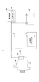
- FIG. 1 is a diagram showing a main configuration of a system including an alternator control device 1 according to an embodiment.
- the alternator control device 1 is a device that controls the alternator 60.
- the alternator 60 is connected to an engine (not shown) and generates power based on the rotation of the engine.
- the electric power generated by the alternator 60 is consumed by the electric load 50 of the vehicle.
- the electric load 50 has various modes and includes, for example, a starter 52, a blower motor, a wiper, and the like.
- the electric power generated by the alternator 60 may be used for charging the on-vehicle battery 40.
- the alternator control device 1 includes an ECU (Electronic Control Unit) 10 and a LIN (Local Interconnect Network) regulator 20 as shown in FIG.
- the ECU 10 and the LIN regulator 20 are connected via a LIN bus (LIN communication line) 30.
- the ECU 10 and the LIN regulator 20 communicate based on the LIN protocol.
- the LIN protocol is a master / slave system, in which the ECU 10 functions as a master, and the LIN regulator 20 functions as a slave.
- a control device other than the LIN regulator 20 may be connected to the ECU 10 as a slave.
- ECU10 may be comprised as a microcomputer which consists of CPU, ROM, RAM, etc. which were mutually connected via the bus
- the storage device 12 such as a ROM stores LIN communication software.
- the ECU 10 may be realized by any ECU such as an ECU that controls the engine. Further, the function of the ECU 10 may be realized by a plurality of ECUs.
- the ECU 10 generates an instruction signal related to power generation of the alternator 60 and transmits the generated instruction signal to the LIN regulator 20 via the LIN bus 30.
- the instruction signal relating to the power generation of the alternator 60 may be a signal of an arbitrary format instructing a target value relating to the power generation amount of the alternator 60. It may be.
- the ECU 10 transmits an instruction signal to the LIN regulator 20 at a predetermined cycle T1.
- the instruction signal selectively includes a power generation instruction signal that causes the power generation state of the alternator 60 and a no power generation instruction signal that causes the no power generation state of the alternator 60.
- the no-power generation instruction signal is a signal for forming a state where no exciting current is passed through the exciting coil of the alternator 60 (the no-power generation state of the alternator 60).
- the no-power generation instruction signal may be a signal whose instruction value of the output voltage of the alternator 60 is “0”.
- the power generation instruction signal is a signal for forming a state (the power generation state of the alternator 60) in which an excitation current flows through the excitation coil of the alternator 60.
- the power generation instruction signal may be a signal whose instruction value of the output voltage of the alternator 60 is other than “0”.
- the instruction signal includes an instruction value (including an upper limit value) regarding an increase gradient of the output voltage (power generation voltage) of the alternator 60.
- An instruction value related to the excitation current of the alternator 60 may be included.
- the ECU 10 acquires information indicating the on / off state of the starter 52.
- the ECU 10 determines when the engine is started (when starting) based on the starter on signal. For example, the ECU 10 determines that the engine start has started when a starter-on signal is generated. The ECU 10 may determine when the engine is started based on other information (such as an ignition on signal) instead of or in addition to these.
- the ECU 10 transmits a non-power generation instruction signal to the LIN regulator 20 via the LIN bus 30 at a predetermined cycle T1.
- the ECU 10 acquires information (for example, a complete explosion flag) indicating a determination result (complete explosion determination) that the engine has shifted to a complete explosion and information indicating an on / off state of the starter 52. Based on these pieces of information, the ECU 10 detects the completion of engine start. For example, the ECU 10 determines that the engine start is completed when a complete explosion flag is set and a starter off signal is detected. Note that the ECU 10 may determine the completion of engine start based on only the complete explosion flag or only the starter off signal, or instead of or in addition to these, based on other information, You may judge. The operation of the ECU 10 when the engine start is completed will be described later with reference to FIG.
- the LIN regulator 20 may be composed of an IC.
- the LIN regulator 20 preferably has a regulator specification that the German Automobile Manufacturers Association (VDA) promotes standardization.
- VDA German Automobile Manufacturers Association
- the LIN regulator 20 may be an Infineon TLE8880 or a Bosch CR665 having such a regulator specification.
- the LIN regulator 20 may be incorporated in the alternator 60 main body as schematically shown in FIG.
- a battery 40 is connected to the LIN regulator 20.
- the LIN regulator 20 has a function of detecting the voltage (power supply voltage) of the battery 40.
- the LIN regulator 20 detects the power supply voltage every predetermined cycle. This predetermined period may be the same as the predetermined period T1.
- the LIN regulator 20 receives an instruction signal from the ECU 10 via the LIN bus 30. Further, the LIN regulator 20 transmits the detected value of the power supply voltage to the ECU 10 via the LIN bus 30 at predetermined intervals. This predetermined period may be the same as the predetermined period T1. For example, the LIN regulator 20 returns the detected value of the power supply voltage to the ECU 10 as a response signal (response value) to the instruction signal from the ECU 10.
- the LIN regulator 20 controls the alternator 60 so that an instruction value (for example, a target value of the generated voltage) related to the power generation instruction signal is realized.
- the LIN regulator 20 determines the excitation current drive duty (power generation duty) applied to the excitation coil of the alternator 60 so that the instruction value related to the power generation instruction signal is realized.
- the LIN regulator 20 may have a gradual excitation function that gradually changes the power generation duty. When realizing the gradual excitation function, the LIN regulator 20 gradually increases the power generation duty toward the power generation duty corresponding to the instruction value related to the power generation instruction signal. At this time, the LIN regulator 20 may determine an increasing gradient of the power generation duty according to an instruction value related to the increasing gradient that can be included in the instruction signal.
- the LIN regulator 20 When the LIN regulator 20 receives the no power generation instruction signal from the ECU 10, the LIN regulator 20 sets the excitation current applied to the excitation coil of the alternator 60 to 0 (that is, sets the power generation duty to 0%).
- the LIN regulator 20 has a priority charge function for controlling the alternator so that the power generation amount of the alternator 60 becomes higher than a predetermined reference when the detected value of the power supply voltage falls below a predetermined priority charge operation threshold.
- the LIN regulator 20 controls the alternator 60 to operate at the maximum power generation capacity when the detected value of the power supply voltage falls below a predetermined priority charge operation threshold. That is, without realizing the above-described gradual excitation function, the power generation duty of the alternator 60 is set to the maximum duty (100%) at once.
- the power supply capability to the electric load 50 by the alternator 60 increases instantaneously (because of this, the power supply voltage recovers rapidly), for example, when the battery 40 is excessively discharged or the battery 40 deteriorates. Even when the internal resistance is large or when the battery 40 is in a poor contact state, it is possible to prevent malfunction of the electric load 50 due to a decrease in the power supply voltage.
- the priority charge operation threshold value may correspond to an allowable minimum value of the power supply voltage that can maintain the normal operation of the electric load 50, and may be a value obtained by giving a predetermined margin to the allowable minimum value.
- the priority charge function of the LIN regulator 20 is deactivated when a no-power generation instruction signal is received from the ECU 10. That is, under the situation where a no-power generation instruction signal is transmitted from the ECU 10 to the LIN regulator 20, even when the detected value of the power supply voltage falls below a predetermined priority charge operation threshold, the priority charge function is not activated. On the other hand, the priority charge function of the LIN regulator 20 is not hindered by other instruction signals (for example, power generation instruction signals) from the ECU 10.
- the priority charge function works when the detected value of the power supply voltage falls below a predetermined priority charge operation threshold (in this case, the power generation instruction signal Regardless of the indicated value, the power generation control of the alternator 60 based on the priority charge function is executed).
- the LIN regulator 20 is configured not to activate the priority charge function only when the no-power generation instruction signal is received.
- Such a configuration logic related to the relationship between the no-power generation instruction signal and the priority charge function
- VDA German Automobile Manufacturers Association
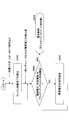
- FIG. 2 is a flowchart showing an example of main processing realized by the ECU 10 in connection with the completion of engine start.
- the process shown in FIG. 2 may be realized by the CPU of the ECU 10 executing the LIN communication software.
- the process shown in FIG. 2 is a process after the engine start is started. Therefore, at the start of the process shown in FIG. 2, the ECU 10 transmits a non-power generation instruction signal to the LIN regulator 20 as described above. Therefore, the alternator 60 is in a no power generation state.
- step 200 the ECU 10 detects the completion of engine start based on, for example, a complete explosion flag or a starter off signal.
- step 202 the ECU 10 determines that the detected value of the power supply voltage is a priority charge operation threshold based on the detected value (latest detected value) of the voltage (power supply voltage) of the battery 40 acquired from the LIN regulator 20 via the LIN bus 30. It is judged whether it is larger than. If the detected value of the power supply voltage is larger than the priority charge operation threshold value, the process proceeds to step 204, and if the detected value of the power supply voltage is smaller than the priority charge operation threshold value, the process proceeds to step 206. When the detected value of the power supply voltage is the same as the priority charge operation threshold value, the process may proceed to either step 204 or 206 (depending on how the priority charge operation threshold value is determined).
- step 204 the ECU 10 stops transmission of the non-power generation instruction signal to the LIN regulator 20, and starts transmission of the power generation instruction signal to enter the normal control state.
- the target value regarding the power generation amount of the alternator 60 in the power generation instruction signal may be determined in an arbitrary manner.
- the power generation voltage of the alternator 60 is optimally controlled according to the vehicle running state. For example, in order to reduce the engine load due to the power generation of the alternator 60, the power generation voltage may be reduced when the vehicle is idling or traveling at a constant speed, and the power generation voltage may be increased when the vehicle is decelerating. Further, at the time of acceleration, the generated voltage of the alternator 60 may be adjusted so that the integrated value of the input / output current of the battery 40 approaches a predetermined target value.
- the ECU 10 determines the target value related to the power generation amount of the alternator 60 as described above, the ECU 10 transmits an instruction signal indicating the target value to the LIN regulator 20 via the LIN bus 30 at a predetermined cycle T1.
- the instruction signal at this time is typically not a no power generation instruction signal, and therefore the alternator 60 shifts from the no power generation state to the power generation state.
- step 206 the ECU 10 continues to transmit the no-power generation instruction signal to the LIN regulator 20, and returns to step 202. In this way, the ECU 10 transmits a no-power generation instruction signal to the LIN regulator 20 at the time of engine start, and after the engine start is completed, until the detected value of the power supply voltage becomes larger than the priority charge operation threshold value. Continue sending the no-power generation instruction signal to the LIN regulator 20 at the time of engine start, and after the engine start is completed, until the detected value of the power supply voltage becomes larger than the priority charge operation threshold value. Continue sending the no-power generation instruction signal to
- the priority charge may be activated immediately after the transmission of the non-power generation instruction signal is stopped, resulting in a decrease in engine speed or an engine stall.
- the transmission of the no-power generation instruction signal is not stopped immediately, but the detected value of the power supply voltage becomes larger than the priority charge operation threshold. The transmission of the no power generation instruction signal is stopped. As a result, it is possible to reduce the possibility of a decrease in engine speed or engine stall after completion of engine start (after completion of explosion determination).
- the ECU 10 starts determining whether or not the detected value of the power supply voltage is larger than the priority charge operation threshold after detecting the completion of the engine start (step 202).
- the determination as to whether or not the detected value of the power supply voltage is larger than the priority charge operation threshold value may be started before the engine start is completed. In this case, when the detected value of the power supply voltage becomes larger than the priority charge operation threshold before the engine start is completed, the normal control state may be entered at that time.
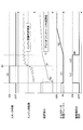
- FIG. 3 is a diagram showing an example of a time series of various states realized by the present embodiment. From the top, the operation state of the starter 52 (on / off state), the engine speed, the power supply voltage, the alternator 60 The power generation duty and the state (on / off state) of the non-power generation instruction signal are shown.
- the engine complete explosion determination threshold when the complete explosion flag is set is indicated by a dotted line.
- the priority charge operation threshold is indicated by a dotted line.
- the ON state of the non-power generation instruction signal corresponds to the state in which the non-power generation instruction signal is transmitted to the LIN regulator 20, and the OFF state of the non-power generation instruction signal indicates the non-power generation instruction signal to the LIN regulator 20. This corresponds to a state in which the transmission of the power generation is stopped (a state in which a power generation instruction signal is transmitted to the LIN regulator 20).
- the power generation duty of the alternator 60 rises to a predetermined value in response to a power generation instruction signal from the ECU 10. Thereafter, the starter 52 is operated (see FIG. 3A), and the power is temporarily taken out from the battery 40, so that the power supply voltage is lowered (see FIG. 3B). From the start of the starter 52 operation (during cranking), a non-power generation instruction signal is transmitted as described above (see (J1) in FIG. 3) in order to improve startability. Thereby, during operation of the starter 52, the power generation duty of the alternator 60 becomes 0% (see FIG. 3C), and the engine startability is improved. When the engine speed reaches the engine complete explosion determination threshold (see FIG.
- the priority charge does not operate. Thereafter, with the transmission of the power generation instruction signal, the power generation duty of the alternator 60 gradually increases (slow excitation function) (see (N) in FIG. 3), and the load torque of the alternator 60 gradually increases after the engine start is completed. Realized.
- the power generation duty of the alternator 60 gradually increases (slow excitation function) (see (N) in FIG. 3), and the load torque of the alternator 60 gradually increases after the engine start is completed. Realized.
- priority charge operation is prevented, and the possibility of engine speed reduction and engine stall is reduced.
- the transmission of the no-power generation instruction signal is started from the start of the operation of the starter 52.
- the start timing of the transmission of the no-power generation instruction signal is arbitrary unless the startability is extremely deteriorated. It is.
- the transmission of the no-power generation instruction signal may be started as soon as possible from the time when the ignition switch is turned on or when the ECU 10 is started. May be started.
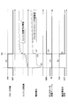
- FIG. 4 is a diagram showing an example of a time series of various states realized by the comparative example, and is a diagram for comparison with FIG. In the comparative example, the transmission of the no power generation instruction signal is immediately stopped when the engine start is completed.
- the power generation duty of the alternator 60 rises to a predetermined value in response to the power generation instruction signal from the ECU 10. Thereafter, the starter 52 is operated (see FIG. 4A), and the power is temporarily taken out from the battery 40, whereby the power supply voltage is lowered (see FIG. 4B). Further, from the start of operation of the starter 52, a non-power generation instruction signal is transmitted in order to improve startability (see (E) of FIG. 4). Thereby, during the operation of the starter 52, the power generation duty of the alternator 60 becomes 0% (see FIG. 4C), and the engine startability is improved. When the engine speed reaches the engine complete explosion determination threshold (see FIG.
- the starter 52 is turned off.
- the transmission of the no power generation instruction signal is stopped (see (I) of FIG. 4).
- the power supply voltage is lower than the priority charge operation threshold (see (G) in FIG. 3). Therefore, when transmission of the no power generation instruction signal is stopped, priority charge is activated immediately. (Refer to FIG. 3H). That is, the power generation duty of the alternator 60 is increased to 100% at a stretch, and sudden power generation is started.
- the power supply voltage is recovered (see (J) in FIG. 3), a sudden increase in power generation becomes a load on the engine, which may cause a decrease in engine speed, engine stall, or the like.
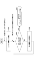
- FIG. 5 is a flowchart showing another example of the main processing realized by the ECU 10 in relation to the completion of engine start.
- the process shown in FIG. 5 may be realized by the CPU of the ECU 10 executing the LIN communication software.
- the process shown in FIG. 5 is a process after the start of engine start, similar to the process shown in FIG. 2 described above. Therefore, at the start of the process shown in FIG. No power generation instruction signal is transmitted. Therefore, the alternator 60 is in a no power generation state.
- Steps 500, 504, and 506 may be the same as steps 200, 204, and 206 shown in FIG.
- step 502 the ECU 10 determines whether or not a predetermined time has elapsed since the starter 52 was turned off. If a predetermined time has elapsed since the starter 52 was turned off, the process proceeds to step 504. If a predetermined time has not elapsed since the starter 52 was turned off, the process proceeds to step 506.
- the predetermined time may be determined in an arbitrary manner, but is adapted by a test or the like so as to correspond to the time from when the starter 52 is turned off to when the power supply voltage becomes larger than the priority charge operation threshold. Good. Since the time from when the starter 52 is turned off to when the power supply voltage becomes larger than the priority charge operation threshold is not constant, an average value of times obtained by tests or the like may be used.
- the time is counted from the time when the starter 52 is turned off, but the starting time may be another equivalent time.
- the time may be counted from the complete explosion determination timing (when the complete explosion flag is set) (in this case, The predetermined time serving as the threshold may be changed as appropriate).
- FIG. 6 is a flowchart showing still another example of the main processing realized by the ECU 10 in relation to the completion of engine start.
- the process shown in FIG. 6 may be realized by the CPU of the ECU 10 executing the LIN communication software.
- the process shown in FIG. 6 is a process after the start of the engine start, similar to the process shown in FIG. 2 described above. Therefore, at the start of the process shown in FIG. No power generation instruction signal is transmitted. Therefore, the alternator 60 is in a no power generation state.
- Steps 600, 604, and 606 may be the same as steps 200, 204, and 206 shown in FIG.
- step 602 the ECU 10 determines that the detected value of the power supply voltage is greater than or equal to a predetermined threshold based on the detected value (latest detected value) of the voltage (power supply voltage) of the battery 40 acquired from the LIN regulator 20 via the LIN bus 30. It is determined whether or not there is. If the detected value of the power supply voltage is larger than the predetermined threshold value, the process proceeds to step 604. If the detected value of the power supply voltage is smaller than the predetermined threshold value, the process proceeds to step 606. When the detected value of the power supply voltage is the same as the predetermined threshold value, the process may proceed to either step 604 or 606 (depending on how the predetermined threshold value is determined).
- the predetermined threshold is set to a value different from the priority charge operation threshold. If the predetermined threshold value is larger than the priority charge operation threshold value, it is disadvantageous in that the start timing of power generation by the alternator 60 is delayed. Therefore, the predetermined threshold is preferably set to a value slightly larger than the priority charge operation threshold. However, the predetermined threshold value may be set to a value smaller than the priority charge operation threshold value. In this case, if the transmission of the no power generation instruction signal is stopped, the priority charge may be activated, which may cause a decrease in engine speed, engine stall, etc., which is disadvantageous compared to the processing shown in FIG. Become. However, even in this case, the timing at which the priority charge can be operated is delayed compared to the comparative example (see FIG. 4), and accordingly, there is a possibility that the engine speed may be lowered or the engine stalled as compared with the comparative example. Can be reduced.
- the transmission of the no-power generation instruction signal is not immediately stopped, but the transmission of the no-power generation instruction signal is continued until the predetermined condition is satisfied. After the determination, the possibility of engine speed reduction and engine stall can be reduced.
- the engine 10 can be reduced in engine speed or engine stall after the engine start is completed simply by appropriately setting the transmission period of the non-power generation instruction signal from the ECU 10 (particularly the transmission stop timing after the engine is started).
- the possibility of occurring can be reduced.
- using the existing function of the highly versatile LIN regulator 20 that conforms to the regulator specifications that the German Automobile Manufacturers Association promotes standardization there is a possibility of engine speed reduction and engine stall after engine startup is complete. Can be reduced.
- the logic incorporated in the LIN regulator 20 that conforms to the regulator specifications promoted by the German Automobile Manufacturers Association (ie, the non-power generation instruction signal having a higher priority than the priority charge function is enabled). Therefore, it is possible to reduce the possibility of engine speed reduction and engine stall after engine start-up is completed without changing the regulator specifications.
- the start timing of the starter 52 is the same as the timing of the complete explosion determination (that is, the starter 52 is turned off when the complete explosion determination is made). There may be a time difference between the off timing and the complete explosion determination timing.
- the process of step 202 in FIG. 2 (the process in step 502 in FIG. 5 and the process in step 602 in FIG. 6) is started at any timing of the starter 52 off timing and the complete explosion determination timing. May be.
- the no-power generation instruction signal which is the only control signal with higher priority than the priority charge function
- the LIN regulator 20 is a signal that causes the alternator 60 to generate a non-power generation state.
- the non-power generation instruction signal is generated by the LIN regulator 20 in the power generation suppression state of the alternator 60 A signal that forms a state more suppressed than when the charge function is activated may be included.
- the name “no power generation instruction signal” is a name given for the sake of convenience, and the name is arbitrary. In the current specification, the “no power generation instruction signal” is an instruction signal including an instruction value “0X00”.
- ECU 20 ECU 20 LIN regulator 30 LIN bus 40 battery 50 electric load 52 starter 60 alternator
Landscapes
- Engineering & Computer Science (AREA)
- Power Engineering (AREA)
- Control Of Eletrric Generators (AREA)
Abstract
Description
オルタネータを制御する第1制御装置と、
前記第1制御装置に、前記オルタネータの発電に関する指示信号を周期的に送信する第2制御装置とを備え、
前記指示信号は、前記オルタネータの発電状態を引き起こす発電指示信号と、前記オルタネータの無発電状態又は発電抑制状態を引き起こす無発電指示信号とを選択的に含み、
前記第1制御装置は、電源電圧の検出値が所定閾値より小さい場合であって、前記第1制御装置から前記発電指示信号を受信する場合には、前記オルタネータの発電量が所定基準より高くなるように制御する一方、電源電圧の検出値が前記所定閾値より小さい場合であって、前記第1制御装置から前記無発電指示信号を受信する場合には、前記無発電指示信号に従って前記オルタネータの無発電状態又は発電抑制状態を形成又は維持し、
前記第2制御装置は、エンジン始動完了後において、所定条件が成立するまで前記無発電指示信号を前記第1制御装置に周期的に送信することを特徴とする、オルタネータ制御装置が提供される。
20 LINレギュレータ
30 LINバス
40 バッテリ
50 電気負荷
52 スタータ
60 オルタネータ
Claims (9)
- オルタネータ制御装置であって、
オルタネータを制御する第1制御装置と、
前記第1制御装置に、前記オルタネータの発電に関する指示信号を周期的に送信する第2制御装置とを備え、
前記指示信号は、前記オルタネータの発電状態を引き起こす発電指示信号と、前記オルタネータの無発電状態又は発電抑制状態を引き起こす無発電指示信号とを選択的に含み、
前記第1制御装置は、電源電圧の検出値が所定閾値より小さい場合であって、前記第2制御装置から前記発電指示信号を受信する場合には、前記オルタネータの発電量が所定基準より高くなるように制御する一方、電源電圧の検出値が前記所定閾値より小さい場合であって、前記第2制御装置から前記無発電指示信号を受信する場合には、前記無発電指示信号に従って前記オルタネータの無発電状態又は発電抑制状態を形成又は維持し、
前記第2制御装置は、エンジン始動完了後において、所定条件が成立するまで前記無発電指示信号を前記第1制御装置に周期的に送信することを特徴とする、オルタネータ制御装置。 - 前記所定条件は、電源電圧の検出値が所定基準値より大きくなることである、請求項1に記載のオルタネータ制御装置。
- 前記所定基準値は、前記所定閾値と等しい、請求項2に記載のオルタネータ制御装置。
- 前記所定条件は、エンジン始動完了後から所定時間経過したことである、請求項1に記載のオルタネータ制御装置。
- 前記第2制御装置は、スタータ作動時又はそれ以前に前記無発電指示信号の送信を開始し、前記所定条件が成立するまで前記無発電指示信号を前記第1制御装置に周期的に送信する、請求項1~4のうちのいずれか1項に記載のオルタネータ制御装置。
- 前記エンジン始動完了後は、エンジンが完爆に移行したと判定する完爆判定後である、請求項1に記載のオルタネータ制御装置。
- 前記第1制御装置は、電源電圧の検出値が所定閾値以下となった場合であって、前記第1制御装置から前記発電指示信号を受信する場合には、前記発電指示信号とは無関係に、最大の発電デューティで前記オルタネータを制御する、請求項1~6のうちのいずれか1項に記載のオルタネータ制御装置。
- 前記第1制御装置は、LIN(Local
Interconnect Network)プロトコルに適合したレギュレータであり、前記第1制御装置と前記第2制御装置とは、LINプロトコルに基づいて通信する、請求項1~7のうちのいずれか1項に記載のオルタネータ制御装置。 - オルタネータを制御するレギュレータに、前記オルタネータの発電に関する指示信号であって、前記オルタネータの発電状態を引き起こす発電指示信号と、前記オルタネータの無発電状態又は発電抑制状態を引き起こす無発電指示信号とを選択的に含む指示信号を周期的に送信する制御装置であって、前記レギュレータが、電源電圧の検出値が所定閾値より小さい場合であって、前記発電指示信号を受信する場合には、前記発電指示信号とは無関係に、最大の発電デューティで前記オルタネータを制御する一方、電源電圧の検出値が前記所定閾値より小さい場合であって、前記無発電指示信号を受信する場合には、前記無発電指示信号に従って前記オルタネータの無発電状態又は発電抑制状態を形成又は維持する、制御装置において、
エンジン始動完了後において、所定条件が成立するまで前記無発電指示信号を前記レギュレータに周期的に送信することを特徴とする、制御装置。
Priority Applications (7)
| Application Number | Priority Date | Filing Date | Title |
|---|---|---|---|
| JP2014545527A JP5850173B2 (ja) | 2012-11-09 | 2012-11-09 | オルタネータ制御装置 |
| CN201280076904.1A CN104769835B (zh) | 2012-11-09 | 2012-11-09 | 交流发电机控制装置 |
| PCT/JP2012/079186 WO2014073097A1 (ja) | 2012-11-09 | 2012-11-09 | オルタネータ制御装置 |
| BR112015009955A BR112015009955A2 (pt) | 2012-11-09 | 2012-11-09 | aparelho de controle de alternador e controlador que transmite periodicamente sinal de instrução para regulador que controla o alternador |
| EP12888118.2A EP2919381B1 (en) | 2012-11-09 | 2012-11-09 | Alternator control apparatus |
| US14/440,220 US9455657B2 (en) | 2012-11-09 | 2012-11-09 | Alternator control apparatus |
| IN2111DEN2015 IN2015DN02111A (ja) | 2012-11-09 | 2015-03-16 |
Applications Claiming Priority (1)
| Application Number | Priority Date | Filing Date | Title |
|---|---|---|---|
| PCT/JP2012/079186 WO2014073097A1 (ja) | 2012-11-09 | 2012-11-09 | オルタネータ制御装置 |
Publications (1)
| Publication Number | Publication Date |
|---|---|
| WO2014073097A1 true WO2014073097A1 (ja) | 2014-05-15 |
Family
ID=50684234
Family Applications (1)
| Application Number | Title | Priority Date | Filing Date |
|---|---|---|---|
| PCT/JP2012/079186 Ceased WO2014073097A1 (ja) | 2012-11-09 | 2012-11-09 | オルタネータ制御装置 |
Country Status (7)
| Country | Link |
|---|---|
| US (1) | US9455657B2 (ja) |
| EP (1) | EP2919381B1 (ja) |
| JP (1) | JP5850173B2 (ja) |
| CN (1) | CN104769835B (ja) |
| BR (1) | BR112015009955A2 (ja) |
| IN (1) | IN2015DN02111A (ja) |
| WO (1) | WO2014073097A1 (ja) |
Cited By (2)
| Publication number | Priority date | Publication date | Assignee | Title |
|---|---|---|---|---|
| JP2016133030A (ja) * | 2015-01-19 | 2016-07-25 | 株式会社デンソー | 電力制御装置 |
| JP2018207658A (ja) * | 2017-06-02 | 2018-12-27 | スズキ株式会社 | 発電制御装置 |
Families Citing this family (6)
| Publication number | Priority date | Publication date | Assignee | Title |
|---|---|---|---|---|
| CN104768803B (zh) * | 2012-08-10 | 2016-10-12 | 丰田自动车株式会社 | 交流发电机控制装置 |
| FR2996703B1 (fr) * | 2012-10-10 | 2015-03-20 | Renault Sas | Procede de recuperation d'energie electrique avec lissage de tension sur un reseau electrique embarque |
| FR3027745B1 (fr) * | 2014-10-27 | 2016-11-04 | Valeo Equip Electr Moteur | Regulateur porte-balais d'alternateur de vehicule automobile |
| JP2018006187A (ja) * | 2016-07-04 | 2018-01-11 | 株式会社オートネットワーク技術研究所 | 駆動装置 |
| CN106330030A (zh) * | 2016-09-22 | 2017-01-11 | 东莞市港奇电子有限公司 | 一种智能调节发电量的方法和装置 |
| US11223225B2 (en) | 2019-09-09 | 2022-01-11 | Deere & Company | Intelligent starting and charging system and method |
Citations (7)
| Publication number | Priority date | Publication date | Assignee | Title |
|---|---|---|---|---|
| JPS59157555U (ja) * | 1983-03-28 | 1984-10-23 | マツダ株式会社 | エンジンの始動制御装置 |
| JPS61171879A (ja) * | 1985-01-28 | 1986-08-02 | Daihatsu Motor Co Ltd | オルタネ−タ制御装置 |
| JPH06284597A (ja) * | 1993-03-31 | 1994-10-07 | Fujitsu Ten Ltd | オルタネータ制御装置 |
| JPH099695A (ja) * | 1995-06-23 | 1997-01-10 | Nippondenso Co Ltd | 車両用電源装置 |
| JP2004274842A (ja) * | 2003-03-06 | 2004-09-30 | Suzuki Motor Corp | 交流発電機の発電制御装置 |
| JP2010263720A (ja) | 2009-05-08 | 2010-11-18 | Denso Corp | 車両用発電制御装置 |
| JP2011200062A (ja) * | 2010-03-23 | 2011-10-06 | Denso Corp | 車両用発電制御装置 |
Family Cites Families (7)
| Publication number | Priority date | Publication date | Assignee | Title |
|---|---|---|---|---|
| JP3414310B2 (ja) * | 1998-09-25 | 2003-06-09 | トヨタ自動車株式会社 | エンジンの始動制御装置 |
| JP2004080931A (ja) * | 2002-08-20 | 2004-03-11 | Kokusan Denki Co Ltd | 内燃機関用スタータジェネレータ |
| JP3688673B2 (ja) * | 2002-10-01 | 2005-08-31 | 本田技研工業株式会社 | 永久磁石式回転電機の制御装置 |
| JP2005009474A (ja) * | 2003-05-26 | 2005-01-13 | Toyota Motor Corp | 動力出力装置およびその制御方法 |
| US7342382B1 (en) * | 2004-02-03 | 2008-03-11 | Dana Corporation | Method of determining transition from starter to alternator function by monitoring battery voltage or current |
| JP4124209B2 (ja) * | 2005-03-23 | 2008-07-23 | 株式会社デンソー | 発電制御装置 |
| CN1933321B (zh) * | 2005-09-13 | 2012-12-05 | 三菱电机株式会社 | 原动机输出的控制装置 |
-
2012
- 2012-11-09 EP EP12888118.2A patent/EP2919381B1/en not_active Not-in-force
- 2012-11-09 CN CN201280076904.1A patent/CN104769835B/zh not_active Expired - Fee Related
- 2012-11-09 BR BR112015009955A patent/BR112015009955A2/pt not_active Application Discontinuation
- 2012-11-09 US US14/440,220 patent/US9455657B2/en not_active Expired - Fee Related
- 2012-11-09 WO PCT/JP2012/079186 patent/WO2014073097A1/ja not_active Ceased
- 2012-11-09 JP JP2014545527A patent/JP5850173B2/ja active Active
-
2015
- 2015-03-16 IN IN2111DEN2015 patent/IN2015DN02111A/en unknown
Patent Citations (7)
| Publication number | Priority date | Publication date | Assignee | Title |
|---|---|---|---|---|
| JPS59157555U (ja) * | 1983-03-28 | 1984-10-23 | マツダ株式会社 | エンジンの始動制御装置 |
| JPS61171879A (ja) * | 1985-01-28 | 1986-08-02 | Daihatsu Motor Co Ltd | オルタネ−タ制御装置 |
| JPH06284597A (ja) * | 1993-03-31 | 1994-10-07 | Fujitsu Ten Ltd | オルタネータ制御装置 |
| JPH099695A (ja) * | 1995-06-23 | 1997-01-10 | Nippondenso Co Ltd | 車両用電源装置 |
| JP2004274842A (ja) * | 2003-03-06 | 2004-09-30 | Suzuki Motor Corp | 交流発電機の発電制御装置 |
| JP2010263720A (ja) | 2009-05-08 | 2010-11-18 | Denso Corp | 車両用発電制御装置 |
| JP2011200062A (ja) * | 2010-03-23 | 2011-10-06 | Denso Corp | 車両用発電制御装置 |
Cited By (2)
| Publication number | Priority date | Publication date | Assignee | Title |
|---|---|---|---|---|
| JP2016133030A (ja) * | 2015-01-19 | 2016-07-25 | 株式会社デンソー | 電力制御装置 |
| JP2018207658A (ja) * | 2017-06-02 | 2018-12-27 | スズキ株式会社 | 発電制御装置 |
Also Published As
| Publication number | Publication date |
|---|---|
| BR112015009955A2 (pt) | 2017-07-11 |
| CN104769835B (zh) | 2018-01-26 |
| EP2919381B1 (en) | 2019-02-13 |
| JP5850173B2 (ja) | 2016-02-03 |
| EP2919381A1 (en) | 2015-09-16 |
| IN2015DN02111A (ja) | 2015-08-14 |
| US9455657B2 (en) | 2016-09-27 |
| EP2919381A4 (en) | 2016-06-29 |
| JPWO2014073097A1 (ja) | 2016-09-08 |
| CN104769835A (zh) | 2015-07-08 |
| US20150303853A1 (en) | 2015-10-22 |
Similar Documents
| Publication | Publication Date | Title |
|---|---|---|
| JP5850173B2 (ja) | オルタネータ制御装置 | |
| US8763578B2 (en) | Vehicle drive having at least two starting systems | |
| JP5035431B2 (ja) | 車両制御システム | |
| JP2018133914A (ja) | 車両用電源システム | |
| JP5928177B2 (ja) | トルクアシスト制御装置 | |
| WO2016125852A1 (ja) | 自動車用電源装置及び自動車用電源装置の制御方法 | |
| EP3499010A1 (en) | Method and device for controlling vehicle including idle stop and go function | |
| JP6356591B2 (ja) | バッテリ監視装置 | |
| JP2015123824A (ja) | 車両用電源装置 | |
| JP2012246867A (ja) | アイドルストップ制御装置 | |
| JP7521554B2 (ja) | 車両の制御装置 | |
| JP5822025B2 (ja) | オルタネータ制御装置 | |
| JP2015123823A (ja) | 車両用電源装置 | |
| JP2015161253A (ja) | アイドルストップ車の制御装置 | |
| JP5353422B2 (ja) | 車両用発電制御装置 | |
| JP6682383B2 (ja) | 車両用制御装置 | |
| JP6667960B2 (ja) | 車両用制御装置 | |
| CN105899799A (zh) | 发动机起动装置 | |
| CN107813779B (zh) | 车辆用电源装置 | |
| JP6851743B2 (ja) | ジャンピングスタート判定装置 | |
| JP7292789B2 (ja) | 車両制御装置 | |
| JP4569580B2 (ja) | 車両およびその制御方法 | |
| JP2007209106A (ja) | 負荷制御装置、負荷装置及び負荷制御方法 | |
| JP2017008738A (ja) | エンジン始動装置 | |
| CN116215490A (zh) | 控制装置 |
Legal Events
| Date | Code | Title | Description |
|---|---|---|---|
| 121 | Ep: the epo has been informed by wipo that ep was designated in this application |
Ref document number: 12888118 Country of ref document: EP Kind code of ref document: A1 |
|
| ENP | Entry into the national phase |
Ref document number: 2014545527 Country of ref document: JP Kind code of ref document: A |
|
| WWE | Wipo information: entry into national phase |
Ref document number: 2012888118 Country of ref document: EP |
|
| WWE | Wipo information: entry into national phase |
Ref document number: 14440220 Country of ref document: US |
|
| NENP | Non-entry into the national phase |
Ref country code: DE |
|
| REG | Reference to national code |
Ref country code: BR Ref legal event code: B01A Ref document number: 112015009955 Country of ref document: BR |
|
| ENP | Entry into the national phase |
Ref document number: 112015009955 Country of ref document: BR Kind code of ref document: A2 Effective date: 20150430 |